EP3281509A1 - Einzelkornsäeinheit - Google Patents
Einzelkornsäeinheit Download PDFInfo
- Publication number
- EP3281509A1 EP3281509A1 EP17401085.0A EP17401085A EP3281509A1 EP 3281509 A1 EP3281509 A1 EP 3281509A1 EP 17401085 A EP17401085 A EP 17401085A EP 3281509 A1 EP3281509 A1 EP 3281509A1
- Authority
- EP
- European Patent Office
- Prior art keywords
- einzelkornsäeinheit
- seed
- roller
- coulter
- carrier
- Prior art date
- Legal status (The legal status is an assumption and is not a legal conclusion. Google has not performed a legal analysis and makes no representation as to the accuracy of the status listed.)
- Granted
Links
- 238000005096 rolling process Methods 0.000 claims abstract description 11
- 238000009331 sowing Methods 0.000 claims abstract description 4
- 238000009963 fulling Methods 0.000 claims abstract 2
- 238000000926 separation method Methods 0.000 claims description 5
- 230000002093 peripheral effect Effects 0.000 claims description 2
- 238000003860 storage Methods 0.000 abstract description 17
- 235000013339 cereals Nutrition 0.000 description 9
- 239000002689 soil Substances 0.000 description 4
- 238000000151 deposition Methods 0.000 description 3
- 241001632427 Radiola Species 0.000 description 2
- 240000008042 Zea mays Species 0.000 description 2
- 235000016383 Zea mays subsp huehuetenangensis Nutrition 0.000 description 2
- 235000002017 Zea mays subsp mays Nutrition 0.000 description 2
- 244000144992 flock Species 0.000 description 2
- 235000009973 maize Nutrition 0.000 description 2
- 238000003825 pressing Methods 0.000 description 2
- 239000004575 stone Substances 0.000 description 2
- 235000020238 sunflower seed Nutrition 0.000 description 2
- 240000002791 Brassica napus Species 0.000 description 1
- 235000011293 Brassica napus Nutrition 0.000 description 1
- 108010016634 Seed Storage Proteins Proteins 0.000 description 1
- 230000006978 adaptation Effects 0.000 description 1
- 239000004464 cereal grain Substances 0.000 description 1
- 238000005520 cutting process Methods 0.000 description 1
- 230000001788 irregular Effects 0.000 description 1
- 239000000463 material Substances 0.000 description 1
- 230000001681 protective effect Effects 0.000 description 1
- 238000010079 rubber tapping Methods 0.000 description 1
- 230000035939 shock Effects 0.000 description 1
Images

Classifications
-
- A—HUMAN NECESSITIES
- A01—AGRICULTURE; FORESTRY; ANIMAL HUSBANDRY; HUNTING; TRAPPING; FISHING
- A01C—PLANTING; SOWING; FERTILISING
- A01C5/00—Making or covering furrows or holes for sowing, planting or manuring
- A01C5/06—Machines for making or covering drills or furrows for sowing or planting
- A01C5/066—Devices for covering drills or furrows
- A01C5/068—Furrow packing devices, e.g. press wheels
-
- A—HUMAN NECESSITIES
- A01—AGRICULTURE; FORESTRY; ANIMAL HUSBANDRY; HUNTING; TRAPPING; FISHING
- A01C—PLANTING; SOWING; FERTILISING
- A01C7/00—Sowing
- A01C7/20—Parts of seeders for conducting and depositing seed
- A01C7/206—Seed pipes
Definitions
- the invention relates to a Einzelkornsäech according to the preamble of claim 1 and a seeder with several Einzelkornsäticianen.
- Precision seed drills with single grain sowing units arranged in a row at right angles to the direction of travel are used for the multi-row discharge of seeds, such as maize kernels, sunflower seeds or rape kernels, in defined depositing intervals.
- seeds such as maize kernels, sunflower seeds or rape kernels
- machines with a separate separating device per single-grain unit have proven to be suitable. This can be achieved in the direction of travel comparatively uniform storage distances.
- Such a seeder is for example in the EP 2 480 063 B1 described. Accordingly, seed grains from the separating device are each guided through a seed channel into a region between the blade and one of these trailing catching rollers, deposited on the base of the furrow formed by the blade and pressed there by the catching roller. From the EP 0 038 241 B1 it is also known, a lower end portion of the seed channel in such a way that seeds are deposited immediately in front of the running surface of the fishing reel.
- the catching roll In order to maintain a correct spacing between the individual seeds in the direction of travel and for correct pressing of the seed grains, the catching roll should constantly roll on the furrow bottom during working operation.
- the problem is that a rolling contact of the tiller with the furrow base could not always be guaranteed, especially if the leading crowd runs over surveys, for example, over a larger stone.
- the flock and the flock of haulers then pick up the rigidly connected tiller and the seed channel. The result is an imprecise storage of the seed. This could be counteracted by slower working. This is uneconomical.
- the object is achieved with a Einzelkornsäech for a seeder according to claim 1.
- the Einzelkornsätician therefore comprises a share carrier with a share attached thereto, a separating device, a fishing roll and a seed channel leading from the separating device to the fishing roll.
- the catch roller and a lower end portion of the seed channel are attached to a movable with respect to the coulter carrier catcher carrier.
- the vertical position of the catch roller carrier and thus the vertical position of the catch roller and the lower end portion of the seed channel, from the vertical position of the coulter with the attached crowd share it. Consequently, the crowd can run over hills in the field soil, without lifting the catch roll from a furrow ground created by the crowd. Furthermore, the lower end portion of the seed channel remains in the groove. Thus, the seed is reliably stored in the furrow and maintain the ground contact of the fishing reel in working mode consistently.
- the tapping roll therefore rolls continuously with the working speed of the Einzelkornsätician in the furrow bottom.
- the catching roller then carries out the same rolling movement for all seed grains transported in the seed channel, whereby a predetermined spacing in the direction of travel for all seed grains can be maintained.
- the seeds are reliably pressed at the furrow bottom of the fishing reel.
- the blade may comprise two cutting disks forming a groove of substantially rectangular cross-section.
- the following catching roll preferably closes positively on the furrow bottom and the side walls of the furrow, so that the seeds are collected, deposited in the furrow and pressed.
- the separating device is attached to the coulter carrier.
- the coulter carrier In the area of the coulter, comparatively low work-related shocks and vibrations occur. This allows a particularly precise and reliable operation of the separating device. In principle, however, an attachment of the separating device to the catch roller carrier would be conceivable.
- the catch roller carrier comprises a rocker or a parallelogram linkage with vertical mobility of the fishing reel and the lower end portion.
- Swing arms are relatively simple and robust. By definition they allow a common vertical pivoting of the catching roller and the lower end section of the seed channel.
- a parallelogram linkage allows a stroke of the fishing reel and the lower end portion without additional change the rotational position, as in a rigid load guidance.
- the catch roller carrier is spring-biased downwards and in particular biased relative to the coulter carrier to press the catch roller to a furrow bottom created by the coulter. This allows a particularly reliable ground contact of the fishing reel on uneven ground and thus a uniform rolling of the fishing reel with the working speed of Einzelkornsätician.
- the seed channel comprises at least one flexible tube between the separating device and the lower end portion. This allows a flexible positioning of the lower end portion with respect to the separating device.
- the seed channel comprises at least one telescoping section between the singulating device and the lower end section.
- vertical relative movements between the separating device and the lower end section can also be compensated in a rigid section of the seed channel.
- the singling device is designed for separating the seed with a substantially uniform singling distance between individual seed grains of the seed.
- the seeds can then be passed as a uniform stream of seed in a storage area immediately in front of the fishing reel and pressed there from this with corresponding uniform storage distances at the bottom of the furrow.
- the end portion of the seed channel is fixed rigidly in the operating mode with respect to the tiller.
- the spatial arrangement of the catch roller and the lower end portion of the seed channel does not change even with vertical evasive movements of the crowd. This allows a reproducible at any time reproduce the seeds from the seed channel in the storage area immediately before the Fangrolle.
- the catching roller and the end portion of the seed channel are arranged such that a connection angle of the end portion to a peripheral tangent of the fishing reel is 5 ° to 15 °. This allows a reliable depositing of the seeds in a storage area immediately before or below the running surface of the fishing reel. This promotes a pressing of the seeds at the furrow bottom under uniform storage distances in the direction of travel.
- connection angle is fixed or adjustable. This allows reproducible and / or adapted to the respective seed storage conditions for the seeds between Fangrolle and furrow ground produce.
- the tread roll preferably has a running surface, which rolls unyieldingly in working mode, for example from a substantially rigid material.
- a running surface which rolls unyieldingly in working mode, for example from a substantially rigid material.
- the crowd is formed as a single disc, double disc or drag coulter. This allows for the respective seed suitable furrow cross-sections produced in each to working arable land.
- the stated object is also achieved with a precision seed drill comprising at least six working in operation in transverse row arranged Einzelkornsäechen according to one of the previous embodiments.
- the Einzelkornsäticianen are arranged, for example, on a common frame, for example, on one or more crossbar, with external crossbars can then fold up before / after working in a known manner upwards.
- Particularly advantageous for economic adaptation of the working width are frames for carrying at least 8 to 20 arranged in transverse rows Einzelkornsäajien.
- the Einzelkornsätician 1 comprises in a preferred embodiment, a coulter support 2 with a share 3 attached thereto, a separation device 4 for seed, a fishing reel 5 and a seed channel 6 leading from the singulator 4 to the fishing reel 5.
- the seed channel 6 comprises a lower end portion 6a, which is fastened together with the catching roller 5 on a catching roller carrier 7.
- the lower end portion 6a operates, for example, as a storage chute for the occasionally arriving seed.
- the catching roller carrier 7 preferably comprises a rocker 7a tiltable about a horizontal axis 8, a fork 7b attached thereto for supporting the catching roller 5 and a front protective plate 7c for the catching roller 5.
- the rocker 7a is mounted on the coulter carrier 2.
- the fishing reel 5 with respect to the coulter 2 and / or the crowd 3 is vertically movable.
- the coulter carrier 2 is mounted vertically pivotable about a horizontal axis 9 on a front connection carrier 10.
- the connection carrier 10 is used to attach the Einzelkornsätician 1 on a (not shown) frame a seeder.
- the arrangement of several Einzelkornsäticianen 1 in transverse row on a seeder is known per se and therefore not further explained at this point.
- the catch roller carrier 7 is resiliently biased downwards, for example with the aid of at least one spring element 11, in order to press down the catch roller 5 for producing a continuous ground contact during operation.
- a pinch roller carrier 12 which is connected in a vertically movable manner to the share carrier 2, is known for a pressure roller 13 known per se.
- the spring element 11 acts, for example, between the catch roller carrier 7 and the coulter carrier 2 and / or between the catch roller carrier 7 and the pressure roller carrier 12.
- FIG. 2A shows the driving of a flat field soil 15 in the direction of travel 1a, in which the blade 3 produces a groove 16 with a groove bottom 16a. Behind it, the fishing reel 5 rolls continuously on the flat furrow bottom 16a.
- the pressure roller 13 is in the FIG. 2A shown in a position on the soil 15 above the furrow 16.
- FIG. 2B clarified in a section of the FIG. 2A in that the separating device 4 blows isolated seeds in the form of seed grains 17 through the seed channel 6 into a depositing area 18 immediately in front of the contact area 19 of the catching roller 5 with the furrow bottom 16a.
- the seed channel 6 comprises at least one flexible and / or telescopic (not shown) upper portion 6b above the rigid lower end portion 6a.
- the lower end portion 6a of the seed channel 6 is rigidly connected, for example, on the rocker 7a and / or on the guard plate 7c with the catch roller carrier 7.
- the example blade-shaped lower end portion 6a of the seed channel 6 forms with a circumferential tangent 5a of the catching roller 5 preferably a connection angle ⁇ of 5 ° to 15 °, see the Figure 2C ,
- Position and orientation of the lower end portion 6a, in particular the connection angle ⁇ , can preferably be fixed and / or set.
- FIG. 3A illustrates, even when driving on a bump 15a in the field soil 15, which is in particular a survey such as a large stone, the tiller roller 5 maintains a rolling contact with the groove bottom 16a at. This is made possible by the vertical mobility of the catching roller 5 on the catching roller carrier 7 with respect to the coulter carrier 2 and / or the crowd 3.
- the catch roller carrier 7 is pressed by means of the spring element 11 with respect to the coulter 2 down against the groove bottom 16a.
- the FIG. 3A also runs the pinch roller 13 by way of example on the groove bottom 16a.
- the Anyakrollenlie 12 is vertically pivotally mounted on the beam carrier 2. This should make it clear that a continuous contact with the ground of the fishing reel 5 is given to each other even with different vertical positions of the crowd 3, the fishing reel 5 and the pinch roller 13.
- connection angle ⁇ is maintained even when driving over bumps 15a with the crowd 3.
- the basic arrangement of the lower end portion 6a of the seed channel 6 and the fishing reel 5 is maintained to each other in the storage area 18 even with irregular ground conditions. Accordingly, a predetermined storage distance 20 in the direction of travel 1a of the Einzelkornsätician 1 can be reliably maintained. This also allows for maximizing the speed of operation while maintaining uniform spacing 20.
- the separating device 4 ensures a substantially constant separating distance 19.
- associated separating discs and machine parameters are adapted to the seeds to be separated in a suitable and principally known manner.
- the continuous rolling on the furrow bottom 16a Fangrolle 5 takes all seeds 17 in the same way on their tread 5b and thus finally causes a uniform spacing distance 20 of the seed grains 17 along the furrow 16th
- seeds for example maize grains, sunflower seeds, rape seeds, cereal grains or the like come into question.
- the catching roller carrier 7 could comprise a parallelogram linkage (not shown) on which the catching roller 5 and the lower end section 6a of the seed channel 6 are moved vertically with respect to the coulter 2 or the coulter 3 without additional tilting movement could.
- each share 3 is assigned a separate separating device 4 and a fishing reel 5 with a seed channel 6 each.
- each Einzelkornsäticianen 1 is preferably a (not shown) seed container available, from which the individual separating devices 4 are supplied with seed.
- the Einzelkornsäticianen 1 could be mounted depending on the working width of the seeder at their outer ends on vertically pivotable frame, which are folded before / after the operation of the seeder 1 in a known manner upwards.
Landscapes
- Life Sciences & Earth Sciences (AREA)
- Soil Sciences (AREA)
- Environmental Sciences (AREA)
- Sowing (AREA)
Abstract
Description
- Die Erfindung betrifft eine Einzelkornsäeinheit gemäß Oberbegriff des Anspruchs 1 und eine Einzelkornsämaschine mit mehreren Einzelkornsäeinheiten.
- Einzelkornsämaschinen mit quer zur Fahrtrichtung aneinander gereihten Einzelkornsäeinheiten werden für den mehrreihigen Austrag von Saatgut, wie beispielsweise Maiskörner, Sonnenblumenkerne oder Rapskerne, in definierten Ablageabständen verwendet. Bewährt haben sich insbesondere Maschinen mit einer separaten Vereinzelungsvorrichtung pro Einzelkornsäeinheit. Damit lassen sich auch in Fahrtrichtung vergleichsweise einheitliche Ablageabstände erzielen.
- Eine derartige Sämaschine ist beispielsweise in der
EP 2 480 063 B1 beschrieben. Demnach werden Saatkörner aus der Vereinzelungsvorrichtung jeweils durch einen Saatgutkanal in einen Bereich zwischen Schar und einer dieser nachlaufenden Fangrolle geleitet, auf dem Grund der von der Schar gebildeten Furche abgelegt und dort von der Fangrolle angedrückt. Aus derEP 0 038 241 B1 ist es ferner bekannt, einen unteren Endabschnitt des Saatgutkanals so auszubilden, dass Saatkörner unmittelbar vor der Lauffläche der Fangrolle abgelegt werden. - Für die Einhaltung eines korrekten Ablageabstands zwischen den einzelnen Saatkörnern in Fahrtrichtung sowie für ein korrektes Andrücken der Saatkörner sollte die Fangrolle im Arbeitsbetrieb ständig auf dem Furchengrund abrollen. Problematisch ist jedoch, dass ein abrollender Kontakt der Fangrolle mit dem Furchengrund bisher nicht immer gewährleistet werden konnte, vor allem wenn die vorauslaufende Schar über Erhebungen läuft, beispielsweise über einen größeren Stein. Schar und Scharträger heben dann die starr angekoppelte Fangrolle und den Saatgutkanal an. Die Folge ist eine unpräzise Ablage des Saatguts. Dem könnte bedingt durch langsameres Arbeiten entgegengewirkt werden. Dies ist jedoch unwirtschaftlich.
- Es besteht daher der Bedarf für Einzelkornsäeinheiten und Einzelkornsämaschinen, die sowohl eine präzise Ablage der Saatkörner als auch hohe Arbeitsgeschwindigkeiten ermöglichen.
- Die gestellte Aufgabe wird mit einer Einzelkornsäeinheit für eine Einzelkornsämaschine gemäß Anspruch 1 gelöst. Die Einzelkornsäeinheit umfasst demnach einen Scharträger mit einer daran befestigten Schar, eine Vereinzelungsvorrichtung, eine Fangrolle und einen von der Vereinzelungsvorrichtung zur Fangrolle führenden Saatgutkanal. Erfindungsgemäß sind die Fangrolle und ein unterer Endabschnitt des Saatgutkanals an einem bezüglich des Scharträgers beweglichen Fangrollenträger befestigt.
- Dadurch lässt sich die vertikale Position des Fangrollenträgers, und damit die vertikale Position der Fangrolle und des unteren Endabschnitt des Saatgutkanals, von der vertikalen Position des Scharträgers mit der daran befestigten Schar entkoppeln. Folglich kann die Schar über Erhebungen im Ackerboden laufen, ohne dabei die Fangrolle von einem von der Schar erzeugten Furchengrund abzuheben. Ferner bleibt der untere Endabschnitt des Saatgutkanals in der Furche. Somit wird das Saatgut zuverlässig in der Furche abgelegt und der Bodenkontakt der Fangrolle im Arbeitsbetrieb durchweg aufrechterhalten. Die Fangrolle rollt daher kontinuierlich mit der Arbeitsgeschwindigkeit der Einzelkornsäeinheit im Furchengrund ab.
- Die Fangrolle führt dann für alle im Saatgutkanal antransportierten Saatkörner dieselbe Abrollbewegung aus, wodurch ein vorgegebener Ablageabstand in Fahrtrichtung für alle Saatkörner eingehalten werden kann. Außerdem werden die Saatkörner am Furchengrund zuverlässig von der Fangrolle angedrückt.
- Die Schar kann beispielsweise zwei Schneidscheiben umfassen, die eine Furche mit im Wesentlichen rechteckigem Querschnitt ausbildet. Die nachfolgende Fangrolle schließt vorzugsweise am Furchengrund und den Seitenwänden der Furche formschlüssig mit dieser ab, so dass die Saatkörner aufgefangen, in der Furche abgelegt und angedrückt werden.
- Vorzugsweise ist die Vereinzelungsvorrichtung an dem Scharträger befestigt. Im Bereich des Scharträgers treten vergleichsweise geringe arbeitsbedingte Erschütterungen und Vibrationen auf. Dies ermöglicht eine besonders präzise und zuverlässige Arbeitsweise der Vereinzelungsvorrichtung. Prinzipiell wäre jedoch auch eine Befestigung der Vereinzelungsvorrichtung an dem Fangrollenträger denkbar.
- Vorzugsweise umfasst der Fangrollenträger eine Schwinge oder ein Parallelogramm-Gestänge mit vertikaler Beweglichkeit der Fangrolle und des unteren Endabschnitts. Schwingen sind vergleichsweise einfach aufgebaut und robust. Sie ermöglichen per Definition ein gemeinsames vertikales Schwenken der Fangrolle und des unteren Endabschnitts des Saatgutkanals. Ein Parallelogramm-Gestänge ermöglicht dagegen einen Hub der Fangrolle und des unteren Endabschnitts ohne zusätzliche Änderung deren Drehlage, wie bei einer starren Lastführung.
- Vorzugsweise ist der Fangrollenträger nach unten hin federnd und insbesondere gegenüber dem Scharträger vorgespannt, um die Fangrolle an einen von der Schar erzeugten Furchengrund zu drücken. Dies ermöglicht einen besonders zuverlässigen Bodenkontakt der Fangrolle auf unebenem Ackerboden und somit ein gleichmäßiges Abrollen der Fangrolle mit der Arbeitsgeschwindigkeit der Einzelkornsäeinheit.
- Vorzugsweise umfasst der Saatgutkanal wenigstens einen biegsamen Schlauch zwischen der Vereinzelungsvorrichtung und dem unteren Endabschnitt. Dies ermöglicht eine flexible Positionierung des unteren Endabschnitts bezüglich der Vereinzelungsvorrichtung.
- Vorzugsweise umfasst der Saatgutkanal wenigstens einen teleskopartigen Abschnitt zwischen der Vereinzelungsvorrichtung und dem unteren Endabschnitt. Dadurch lassen sich vertikale Relativbewegungen zwischen der Vereinzelungsvorrichtung und dem unteren Endabschnitt auch in einem starren Abschnitt des Saatgutkanals ausgleichen.
- Vorzugsweise ist die Vereinzelungsvorrichtung zur Vereinzelung des Saatguts mit einem im Wesentlichen einheitlichen Vereinzelungsabstand zwischen einzelnen Saatkörnern des Saatguts ausgebildet. Die Saatkörner können dann als gleichmäßiger Saatgutstrom in einen Ablagebereich unmittelbar vor der Fangrolle geleitet und dort von dieser mit entsprechend einheitlichen Ablageabständen am Furchengrund angedrückt werden.
- Vorzugsweise ist der Endabschnitt des Saatgutkanals im Arbeitsbetrieb starr bezüglich der Fangrolle befestigt. Somit ändert sich die räumliche Anordnung der Fangrolle und des unteren Endabschnitts des Saatgutkanals auch bei vertikalen Ausweichbewegungen der Schar nicht. Dies ermöglicht eine jederzeit reproduzierbare Übergabe der Saatkörner vom Saatgutkanal in den Ablagebereich unmittelbar vor der Fangrolle.
- Vorzugsweise sind die Fangrolle und der Endabschnitt des Saatgutkanals derart angeordnet, dass ein Anschlusswinkel des Endabschnitts an eine Umfangstangente der Fangrolle 5° bis 15° beträgt. Dies ermöglicht ein zuverlässiges Ablegen der Saatkörner in einem Ablagebereich unmittelbar vor bzw. unterhalb der Lauffläche der Fangrolle. Dies begünstigt ein Andrücken der Saatkörner am Furchengrund unter gleichmäßigen Ablageabständen in Fahrtrichtung.
- Vorzugsweise ist der Anschlusswinkel dabei fest vorgegeben oder einstellbar. Dadurch lassen sich reproduzierbare und/oder an das jeweilige Saatgut angepasste Ablagebedingungen für die Saatkörner zwischen Fangrolle und Furchengrund herstellen.
- Vorzugsweise weißt die Fangrolle eine im Arbeitsbetrieb unnachgiebig abrollende Lauffläche auf, beispielsweise aus einem im Wesentlichen starren Material. Darunter ist zu verstehen, dass sich die Fangrolle beim Abrollen auf dem Ackerboden, insbesondere an Bodenunebenheiten, nicht nennenswert radial verformt. Derartige Fangrollen laufen besonders stabil und ermöglichen eine besonders zuverlässige und reproduzierbare Ablage der Saatkörner auf dem Furchengrund. Prinzipiell wären aber auch nachgiebig abrollende Fangrollen denkbar, beispielsweise solche mit Niederdruckreifen.
- Vorzugsweise ist die Schar als Einzelscheibe, Doppelscheibe oder Schleppschar ausgebildet. Damit lassen sich für das jeweilige Saatgut geeignete Furchenquerschnitte in den zu jeweils bearbeitenden Ackerböden herstellen.
- Die gestellte Aufgabe wird auch mit einer Einzelkornsämaschine gelöst, die wenigstens sechs im Arbeitsbetrieb in Querreihe angeordnete Einzelkornsäeinheiten gemäß einer der vorigen Ausführungsformen umfasst. Die Einzelkornsäeinheiten sind beispielsweise an einem gemeinsamen Rahmen angeordnet, beispielsweise an einem oder mehreren Querbalken, wobei sich äußere Querbalken dann vor/nach dem Arbeitsbetrieb auf bekannte Weise nach oben klappen lassen. Besonders vorteilhaft zur wirtschaftlichen Anpassung der Arbeitsbreite sind Rahmen zum Tragen von wenigstens 8 bis 20 in Querreihen angeordneten Einzelkornsäeinheiten.
- Eine bevorzugte Ausführungsform der Erfindung ist in den Zeichnungen dargestellt. Es zeigen:
- Figur 1
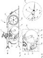
- eine Schrägansicht einer Einzelkornsäeinheit;
- Figuren 2A bis 2C
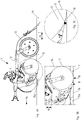
- eine seitliche Ansicht und Teilansichten der Einzelkornsäeinheit beim Befahren eines ebenen Ackerbodens; und
- Figuren 3A bis 3C
- eine seitliche Ansicht und Teilansichten der Einzelkornsäeinheit beim Befahren einer Unebenheit mit der Schar.
- Wie die
Figur 1 erkennen lässt, umfasst die Einzelkornsäeinheit 1 in einer bevorzugten Ausführungsform einen Scharträger 2 mit einer daran befestigten Schar 3, eine Vereinzelungsvorrichtung 4 für Saatgut, eine Fangrolle 5 und einen von der Vereinzelungsvorrichtung 4 zur Fangrolle 5 führenden Saatgutkanal 6. Der Saatgutkanal 6 umfasst einen unteren Endabschnitt 6a, der mit der Fangrolle 5 gemeinsam an einem Fangrollenträger 7 befestigt ist. Der untere Endabschnitt 6a arbeitet beispielsweise als Ablagerutsche für das vereinzelt ankommende Saatgut. - Der Fangrollenträger 7 umfasst vorzugsweise eine um eine horizontale Achse 8 kippbare Schwinge 7a, eine daran befestigte Gabel 7b zu Lagerung der Fangrolle 5 und ein vorderes Schutzblech 7c für die Fangrolle 5. Die Schwinge 7a ist an dem Scharträger 2 gelagert. Somit ist die Fangrolle 5 bezüglich des Scharträgers 2 und/oder der Schar 3 vertikal beweglich.
- Der Scharträger 2 ist um eine horizontale Achse 9 vertikal schwenkbar an einem vorderen Verbindungsträger 10 gelagert. Der Verbindungsträger 10 dient der Befestigung der Einzelkornsäeinheit 1 an einem (nicht dargestellten) Rahmen einer Einzelkornsämaschine. Die Anordnung mehrerer Einzelkornsäeinheiten 1 in Querreihe an einer Einzelkornsämaschine ist an sich bekannt und daher an dieser Stelle nicht weiter erläutert.
- Der Fangrollenträger 7 ist beispielsweise mit Hilfe wenigstens eines Federelements 11 nach unten hin federnd vorgespannt, um die Fangrolle 5 zum Herstellen eines ständigen Bodenkontakts im Arbeitsbetrieb nach unten zu drücken.
- Der Vollständigkeit halber dargestellt ist ferner ein mit dem Scharträger 2 vertikal beweglich verbundener Andruckrollenträger 12 für eine an sich bekannte Andruckrolle 13. Das Federelement 11 wirkt beispielsweise zwischen dem Fangrollenträger 7 und dem Scharträger 2 und/oder zwischen dem Fangrollenträger 7 und dem Andruckrollenträger 12.
- Die
Figur 2A zeigt das Befahren eines ebenen Ackerbodens 15 in Fahrtrichtung 1a, in dem die Schar 3 eine Furche 16 mit einem Furchengrund 16a herstellt. Dahinter rollt die Fangrolle 5 ständig auf dem ebenen Furchengrund 16a ab. Die Andruckrolle 13 ist in derFigur 2A in einer Position auf dem Ackerboden 15 oberhalb der Furche 16 dargestellt. - Die
Figur 2B verdeutlicht in einem Ausschnitt derFigur 2A , dass die Vereinzelungsvorrichtung 4 vereinzeltes Saatgut in Form von Saatkörnern 17 durch den Saatgutkanal 6 bläst bis in einen Ablagebereich 18 unmittelbar vor dem Kontaktbereich 19 der Fangrolle 5 mit dem Furchengrund 16a. - Der Saatgutkanal 6 umfasst oberhalb des starren unteren Endabschnitts 6a wenigstens einen biegsamen und/oder teleskopartigen (nicht gezeigt) oberen Abschnitt 6b.
- Der untere Endabschnitt 6a des Saatgutkanals 6 ist beispielsweise an der Schwinge 7a und/oder an dem Schutzblech 7c starr mit dem Fangrollenträger 7 verbunden. Der beispielsweise schaufelförmige untere Endabschnitt 6a des Saatgutkanals 6 bildet mit einer Umfangstangente 5a der Fangrolle 5 vorzugsweise einen Anschlusswinkel α von 5° bis 15° aus, siehe die
Figur 2C . - Dies ermöglicht eine zielgerichtete Ablage der Saatkörner 17 im Ablagebereich 18, so dass die Saatkörner 17 zuverlässig von der Lauffläche 5b Fangrolle 5 gegen den Furchengrund 16a gedrückt werden. Lage und Ausrichtung des unteren Endabschnitts 6a, insbesondere der Anschlusswinkel α, lassen sich vorzugsweise fest vorgeben und/oder einstellen.
- Wie die
Figur 3A verdeutlicht, behält die Fangrolle 5 auch beim Befahren einer Unebenheit 15a im Ackerboden 15, die insbesondere eine Erhebung wie beispielsweise ein großer Stein ist, einen abrollenden Kontakt mit dem Furchengrund 16a bei. Dies wird durch die vertikale Beweglichkeit der Fangrolle 5 am Fangrollenträger 7 bezüglich des Scharträgers 2 und/oder der Schar 3 ermöglicht. - Ferner wird der Fangrollenträger 7 mit Hilfe des Federelements 11 bezüglich des Scharträgers 2 nach unten gegen den Furchengrund 16a gedrückt. In der
Figur 3A läuft auch die Andruckrolle 13 beispielhaft auf dem Furchengrund 16a. Zudem ist auch der Andruckrollenträger 12 vertikal schwenkbar am Scharträger 2 befestigt. Dies soll verdeutlichen, dass ein ständiger Bodenkontakt der Fangrolle 5 auch bei unterschiedlichen vertikalen Positionen der Schar 3, der Fangrolle 5 und der Andruckrolle 13 zueinander gegeben ist. - In jedem Fall werden die in einem vorgegebenen Vereinzelungsabstand 19 (
Figur 3B ) zueinander durch den Saatgutkanal 6 geleiteten Saatkörner 17 mit einem gleichmäßigen Ablageabstand 20 (Figur 3A ) auf dem Furchengrund 16 abgelegt und dort angedrückt. - Dies wird insbesondere dadurch ermöglicht, dass die Fangrolle 5 auch beim Befahren von Unebenheiten 15a mit der Schar 3 den abrollenden Kontakt zum Furchengrund 16a nicht verliert und somit eine kontinuierliche Abrollbewegung entsprechend der Arbeitsgeschwindigkeit der Einzelkornsäeinheit 1 beziehungsweise der zugehörigen Einzelkornsämaschine einhält.
- Wie der Ausschnitt des Ablagebereichs 18 in der
Figur 3C verdeutlicht, wird der Anschlusswinkel α auch beim Überfahren von Unebenheiten 15a mit der Schar 3 beibehalten. Somit bleibt die grundlegende Anordnung des unteren Endabschnitts 6a des Saatgutkanals 6 und der Fangrolle 5 zueinander im Ablagebereich 18 auch bei unregelmäßiger Bodenbeschaffenheit erhalten. Entsprechend kann ein vorgegebener Ablageabstand 20 in Fahrtrichtung 1a der Einzelkornsäeinheit 1 zuverlässig eingehalten werden. Dies ermöglicht zudem eine Maximierung der Arbeitsgeschwindigkeit bei gleichbleibend einheitlichem Ablageabstand 20. - Die Vereinzelungsvorrichtung 4 sorgt für einen im Wesentlichen konstanten Vereinzelungsabstand 19. Zu diesem Zweck werden zugehörige Vereinzelungsscheiben und Maschinenparameter an die zu vereinzelnden Saatkörner auf geeignete und prinzipiell bekannte Weise angepasst. Die durchgehend auf dem Furchengrund 16a abrollende Fangrolle 5 nimmt alle Saatkörner 17 auf gleiche Weise an ihrer Lauffläche 5b mit und bewirkt so schließlich einen einheitlichen Ablageabstand 20 der Saatkörner 17 entlang der Furche 16.
- Die Anordnung der Vereinzelungsvorrichtung 4 auf dem Scharträger 2, insbesondere in Nähe der Schwenkachse 9, ermöglicht eine vergleichsweise erschütterungsarme und vibrationsarme Arbeitsweise der Vereinzelungsvorrichtung 4 und damit eine zuverlässige und präzise Vereinzelung unterschiedlicher Saatgüter mit einheitlichem Vereinzelungsabstand 19.
- Als Saatgüter kommen beispielsweise Maiskörner, Sonnenblumenkerne, Rapskerne, Getreidekörner oder dergleichen in Frage.
- Anstelle der in den Figuren gezeigten Schwinge 7a könnte der Fangrollenträger 7 ein Parallelogramm-Gestänge (nicht dargestellt) umfassen, an dem die Fangrolle 5 und der untere Endabschnitt 6a des Saatgutkanals 6 ohne zusätzliche Kippbewegung vertikal bezüglich des Scharträgers 2 bzw. der Schar 3 bewegt werden könnten.
- Bei einer Einzelkornsämaschine mit mehreren Einzelkornsäeinheiten 1 ist jeweils jeder Schar 3 eine separate Vereinzelungsvorrichtung 4 und eine Fangrolle 5 mit einem Saatgutkanal 6 zugeordnet. Für mehrere Einzelkornsäeinheiten 1 gemeinsam ist vorzugsweise ein (nicht dargestellter) Saatgutbehälter vorhanden, aus dem die einzelnen Vereinzelungsvorrichtungen 4 mit Saatgut versorgt werden.
- Die Einzelkornsäeinheiten 1 könnten je nach Arbeitsbreite der Einzelkornsämaschine an ihren äußeren Enden auf vertikal schwenkbaren Rahmen montiert sein, die vor/nach dem Arbeitsbetrieb der Einzelkornsämaschine 1 auf bekannte Weise nach oben geklappt werden.
Claims (13)
- Einzelkornsäeinheit (1) für eine Einzelkornsämaschine, umfassend: einen Scharträger (2) mit einer daran befestigten Schar (3); eine Vereinzelungsvorrichtung (4); eine Fangrolle (5); und einen von der Vereinzelungsvorrichtung (4) zur Fangrolle (5) führenden Saatgutkanal (6), dadurch gekennzeichnet, dass die Fangrolle (5) und ein unterer Endabschnitt (6a) des Saatgutkanals (6) an einem bezüglich des Scharträgers (2) beweglichen Fangrollenträger (7) befestigt sind.
- Einzelkornsäeinheit nach Anspruch 1, wobei die Vereinzelungsvorrichtung (4) an dem Scharträger (2) befestigt ist.
- Einzelkornsäeinheit nach Anspruch 1 oder 2, wobei der Fangrollenträger (7) eine Schwinge (7a) oder ein Parallelogramm-Gestänge mit vertikaler Beweglichkeit der Fangrolle (5) und des unteren Endabschnitts (6a) des Saatgutkanals (6) umfasst.
- Einzelkornsäeinheit nach einem der vorigen Ansprüche, wobei der Fangrollenträger (7) nach unten hin federnd vorgespannt ist, insbesondere gegenüber dem Scharträger (2), um die Fangrolle (5) in eine von der Schar (3) gebildete Furche (16) zu drücken.
- Einzelkornsäeinheit nach wenigstens einem der vorigen Ansprüche, wobei der Saatgutkanal (6) zwischen der Vereinzelungsvorrichtung (4) und dem unteren Endabschnitt (6a) wenigstens einen biegsamen Schlauch umfasst.
- Einzelkornsäeinheit nach wenigstens einem der vorigen Ansprüche, wobei der Saatgutkanal (6) wenigstens einen teleskopartigen Abschnitt zwischen der Vereinzelungsvorrichtung (4) und dem unteren Endabschnitt (6a) umfasst.
- Einzelkornsäeinheit nach wenigstens einem der vorigen Ansprüche, wobei die Vereinzelungsvorrichtung (4) zur Vereinzelung des Saatguts mit einem einheitlichen Vereinzelungsabstand (19) zwischen Saatkörnern (17) des Saatguts ausgebildet ist.
- Einzelkornsäeinheit nach wenigstens einem der vorigen Ansprüche, wobei der Endabschnitt (6a) des Saatgutkanals (6) im Arbeitsbetrieb der Einzelkornsäeinheit (1) starr bezüglich der Fangrolle (5) befestigt ist.
- Einzelkornsäeinheit nach wenigstens einem der vorigen Ansprüche, wobei die Fangrolle (5) und der Endabschnitt (6a) des Saatgutkanals (6) derart angeordnet sind, dass ein Anschlusswinkel (α) des Endabschnitts (6a) an eine Umfangstangente (5a) der Fangrolle (5) 5° bis 15° beträgt.
- Einzelkornsäeinheit nach Anspruch 9, wobei der Anschlusswinkel (α) fest vorgegeben oder einstellbar ist.
- Einzelkornsäeinheit nach wenigstens einem der vorigen Ansprüche, wobei die Fangrolle (5) eine unnachgiebig abrollende Lauffläche (5b) aufweist.
- Einzelkornsäeinheit nach wenigstens einem der vorigen Ansprüche, wobei die Schar (3) als Einzelscheibe, Doppelscheibe oder Schleppschar ausgebildet ist.
- Einzelkornsämaschine mit wenigstens sechs im Arbeitsbetrieb in Querreihe angeordneten Einzelkornsäeinheiten (1) nach wenigstens einem der vorigen Ansprüche.
Priority Applications (1)
| Application Number | Priority Date | Filing Date | Title |
|---|---|---|---|
| PL17401085T PL3281509T3 (pl) | 2016-08-09 | 2017-08-01 | Punktowa jednostka siewna |
Applications Claiming Priority (1)
| Application Number | Priority Date | Filing Date | Title |
|---|---|---|---|
| DE102016114692.7A DE102016114692A1 (de) | 2016-08-09 | 2016-08-09 | Einzelkornsäeinheit |
Publications (2)
| Publication Number | Publication Date |
|---|---|
| EP3281509A1 true EP3281509A1 (de) | 2018-02-14 |
| EP3281509B1 EP3281509B1 (de) | 2019-11-13 |
Family
ID=59592997
Family Applications (1)
| Application Number | Title | Priority Date | Filing Date |
|---|---|---|---|
| EP17401085.0A Active EP3281509B1 (de) | 2016-08-09 | 2017-08-01 | Einzelkornsäeinheit |
Country Status (4)
| Country | Link |
|---|---|
| EP (1) | EP3281509B1 (de) |
| DE (1) | DE102016114692A1 (de) |
| HU (1) | HUE047240T2 (de) |
| PL (1) | PL3281509T3 (de) |
Cited By (2)
| Publication number | Priority date | Publication date | Assignee | Title |
|---|---|---|---|---|
| CN113179711A (zh) * | 2021-04-26 | 2021-07-30 | 农业农村部南京农业机械化研究所 | 一种正压播种机用开沟压种覆土装置 |
| CN113179714A (zh) * | 2021-04-26 | 2021-07-30 | 农业农村部南京农业机械化研究所 | 一种气流辅助式精量播种机 |
Families Citing this family (16)
| Publication number | Priority date | Publication date | Assignee | Title |
|---|---|---|---|---|
| DE102019117247A1 (de) * | 2019-06-26 | 2020-12-31 | Lemken Gmbh & Co. Kg | Landwirtschaftliche Sämaschine mit flexibel-längenveränderlicher Förderleitung |
| DE102019117245A1 (de) * | 2019-06-26 | 2020-12-31 | Lemken Gmbh & Co. Kg | Landwirtschaftliche Sämaschine mit längenveränderlicher Förderleitung |
| US11564344B2 (en) | 2019-12-24 | 2023-01-31 | Cnh Industrial America Llc | Particle delivery system of an agricultural row unit |
| US11523556B2 (en) | 2019-12-24 | 2022-12-13 | Cnh Industrial America Llc | Particle delivery system of an agricultural row unit |
| US11553638B2 (en) | 2019-12-24 | 2023-01-17 | Cnh Industrial America Llc | Particle delivery system of an agricultural row unit |
| US11596095B2 (en) | 2019-12-24 | 2023-03-07 | Cnh Industrial America Llc | Particle delivery system of an agricultural row unit |
| US11553639B2 (en) | 2019-12-24 | 2023-01-17 | Cnh Industrial America Llc | Particle delivery system of an agricultural row unit |
| US11483963B2 (en) | 2019-12-24 | 2022-11-01 | Cnh Industrial America Llc | Particle delivery system of an agricultural row unit |
| US11564346B2 (en) | 2019-12-24 | 2023-01-31 | Cnh Industrial America Llc | Particle delivery system of an agricultural row unit |
| US11490558B2 (en) | 2019-12-24 | 2022-11-08 | Cnh Industrial America Llc | Particle delivery system of an agricultural row unit |
| US11516958B2 (en) | 2019-12-24 | 2022-12-06 | Cnh Industrial America Llc | Particle delivery system of an agricultural row unit |
| US11582899B2 (en) | 2019-12-24 | 2023-02-21 | Cnh Industrial America Llc | Particle delivery system of an agricultural row unit |
| US11523555B2 (en) | 2019-12-24 | 2022-12-13 | Cnh Industrial America Llc | Particle delivery system of an agricultural row unit |
| US11589500B2 (en) | 2019-12-24 | 2023-02-28 | Cnh Industrial America Llc | Particle delivery system of an agricultural row unit |
| DE102020134534A1 (de) * | 2020-12-22 | 2022-06-23 | Amazonen-Werke H. Dreyer SE & Co. KG | Verfahren zum Ablegen von Granulatportionen auf eine landwirtschaftliche Nutzfläche mittels einer landwirtschaftlichen Ausbringmaschine |
| DE102022119611A1 (de) | 2022-08-04 | 2024-02-15 | Horsch Maschinen Gmbh | Scharvorrichtung und landwirtschaftliche arbeitsmaschine mit einer mehrzahl derartiger scharvorrichtungen |
Citations (4)
| Publication number | Priority date | Publication date | Assignee | Title |
|---|---|---|---|---|
| EP0038241B1 (de) | 1980-03-31 | 1984-11-28 | Société SOGEFINA Société de Gestion Financière Armoricaine (Société Anonyme) | Verfahren zum Präzisionssäen und Sämaschine, die dieses Verfahren anwendet |
| WO2011037525A1 (en) * | 2009-09-23 | 2011-03-31 | Väderstad-Verken Ab | Seed metering device on an agricultural machine |
| WO2011119095A1 (en) * | 2010-03-23 | 2011-09-29 | Väderstad-Verken Ab | Row unit for a planter, planter and method for planting |
| WO2017036896A1 (de) * | 2015-08-28 | 2017-03-09 | Horsch Maschinen Gmbh | Saescharanordnung einer landwirtschaftlichen maschine |
Family Cites Families (3)
| Publication number | Priority date | Publication date | Assignee | Title |
|---|---|---|---|---|
| GB8325559D0 (en) * | 1983-09-23 | 1983-10-26 | Falcon Agricult Mach | Seed drill |
| DE3517621A1 (de) * | 1985-05-15 | 1986-11-20 | Ernst 7326 Heiningen Weichel | Verfahren und geraetekombination zum ausbringen von saatgut |
| EP0521845A1 (de) * | 1991-07-02 | 1993-01-07 | JANUSCHKOWETZ GmbH | Fahrbare Sämaschine |
-
2016
- 2016-08-09 DE DE102016114692.7A patent/DE102016114692A1/de active Pending
-
2017
- 2017-08-01 PL PL17401085T patent/PL3281509T3/pl unknown
- 2017-08-01 HU HUE17401085A patent/HUE047240T2/hu unknown
- 2017-08-01 EP EP17401085.0A patent/EP3281509B1/de active Active
Patent Citations (5)
| Publication number | Priority date | Publication date | Assignee | Title |
|---|---|---|---|---|
| EP0038241B1 (de) | 1980-03-31 | 1984-11-28 | Société SOGEFINA Société de Gestion Financière Armoricaine (Société Anonyme) | Verfahren zum Präzisionssäen und Sämaschine, die dieses Verfahren anwendet |
| WO2011037525A1 (en) * | 2009-09-23 | 2011-03-31 | Väderstad-Verken Ab | Seed metering device on an agricultural machine |
| EP2480063B1 (de) | 2009-09-23 | 2014-04-23 | Väderstad-Verken AB | Saatgutabmessvorrichtung an einer landwirtschaftsmaschine |
| WO2011119095A1 (en) * | 2010-03-23 | 2011-09-29 | Väderstad-Verken Ab | Row unit for a planter, planter and method for planting |
| WO2017036896A1 (de) * | 2015-08-28 | 2017-03-09 | Horsch Maschinen Gmbh | Saescharanordnung einer landwirtschaftlichen maschine |
Cited By (3)
| Publication number | Priority date | Publication date | Assignee | Title |
|---|---|---|---|---|
| CN113179711A (zh) * | 2021-04-26 | 2021-07-30 | 农业农村部南京农业机械化研究所 | 一种正压播种机用开沟压种覆土装置 |
| CN113179714A (zh) * | 2021-04-26 | 2021-07-30 | 农业农村部南京农业机械化研究所 | 一种气流辅助式精量播种机 |
| CN113179711B (zh) * | 2021-04-26 | 2022-08-12 | 农业农村部南京农业机械化研究所 | 一种正压播种机用开沟压种覆土装置 |
Also Published As
| Publication number | Publication date |
|---|---|
| DE102016114692A1 (de) | 2018-03-01 |
| PL3281509T3 (pl) | 2020-05-18 |
| EP3281509B1 (de) | 2019-11-13 |
| HUE047240T2 (hu) | 2020-04-28 |
Similar Documents
| Publication | Publication Date | Title |
|---|---|---|
| EP3281509B1 (de) | Einzelkornsäeinheit | |
| EP3360403B1 (de) | Säaggregat für eine sämaschine | |
| US11432478B2 (en) | Film deployer, improved trash whipper and improved planter | |
| DE2826658C3 (de) | Sämaschine für Getreide und andere Saatgutarten | |
| EP0629336A1 (de) | Furchenräumeinrichtung für ein landwirtschaftliches Sägerät | |
| EP1585378B1 (de) | Anordnung zum oeffnen und schliessen einer saatfurche | |
| DE102008045132B4 (de) | Säscharanordnung | |
| EP1647174A1 (de) | Landwirtschaftliches Gerät | |
| DE2921183B2 (de) | Furchenöffner für Sä- oder Pflanzmaschinen | |
| DE19730822C2 (de) | Sägerät mit einem Scheibensäschar | |
| EP3395144A1 (de) | Sämaschine zum ausbringen von saatgut und/oder dünger | |
| EP3357317B1 (de) | Scharanordnung für eine sämaschine | |
| DE102007011297B4 (de) | Gezogene Säscharanordnung | |
| WO2019030309A1 (de) | Säschar sowie sämaschine | |
| EP1210853A1 (de) | Bodenbearbeitungsgerät | |
| EP3127412A1 (de) | Landwirtschaftliche maschine zum bearbeiten eines bodens und zum ausbringen von saatgut | |
| DE3336455C2 (de) | Vorrichtung zur Herstellung parallelwandiger Rillen in Grünland und Rasenflächen | |
| DE102012105561B4 (de) | Strohräumer für Drillmaschinen | |
| DE4439441A1 (de) | Einrichtung zum Direktsäen | |
| DE10327377A1 (de) | Sämaschine | |
| EP3357318B1 (de) | Scharaufhängung | |
| EP0704147A2 (de) | Einrichtung zum Direktsäen | |
| EP4260673A1 (de) | Anordnung eines düngeschars mit einem säschar und einem dem düngeschar zugeordneten stützrad | |
| DE102005042459A1 (de) | Sämaschine | |
| WO2021047967A1 (de) | Sävorrichtung |
Legal Events
| Date | Code | Title | Description |
|---|---|---|---|
| PUAI | Public reference made under article 153(3) epc to a published international application that has entered the european phase |
Free format text: ORIGINAL CODE: 0009012 |
|
| STAA | Information on the status of an ep patent application or granted ep patent |
Free format text: STATUS: THE APPLICATION HAS BEEN PUBLISHED |
|
| AK | Designated contracting states |
Kind code of ref document: A1 Designated state(s): AL AT BE BG CH CY CZ DE DK EE ES FI FR GB GR HR HU IE IS IT LI LT LU LV MC MK MT NL NO PL PT RO RS SE SI SK SM TR |
|
| AX | Request for extension of the european patent |
Extension state: BA ME |
|
| STAA | Information on the status of an ep patent application or granted ep patent |
Free format text: STATUS: REQUEST FOR EXAMINATION WAS MADE |
|
| 17P | Request for examination filed |
Effective date: 20180807 |
|
| RBV | Designated contracting states (corrected) |
Designated state(s): AL AT BE BG CH CY CZ DE DK EE ES FI FR GB GR HR HU IE IS IT LI LT LU LV MC MK MT NL NO PL PT RO RS SE SI SK SM TR |
|
| STAA | Information on the status of an ep patent application or granted ep patent |
Free format text: STATUS: EXAMINATION IS IN PROGRESS |
|
| 17Q | First examination report despatched |
Effective date: 20181129 |
|
| GRAP | Despatch of communication of intention to grant a patent |
Free format text: ORIGINAL CODE: EPIDOSNIGR1 |
|
| STAA | Information on the status of an ep patent application or granted ep patent |
Free format text: STATUS: GRANT OF PATENT IS INTENDED |
|
| INTG | Intention to grant announced |
Effective date: 20190827 |
|
| GRAS | Grant fee paid |
Free format text: ORIGINAL CODE: EPIDOSNIGR3 |
|
| GRAA | (expected) grant |
Free format text: ORIGINAL CODE: 0009210 |
|
| STAA | Information on the status of an ep patent application or granted ep patent |
Free format text: STATUS: THE PATENT HAS BEEN GRANTED |
|
| AK | Designated contracting states |
Kind code of ref document: B1 Designated state(s): AL AT BE BG CH CY CZ DE DK EE ES FI FR GB GR HR HU IE IS IT LI LT LU LV MC MK MT NL NO PL PT RO RS SE SI SK SM TR |
|
| REG | Reference to a national code |
Ref country code: CH Ref legal event code: EP Ref country code: AT Ref legal event code: REF Ref document number: 1200699 Country of ref document: AT Kind code of ref document: T Effective date: 20191115 |
|
| REG | Reference to a national code |
Ref country code: DE Ref legal event code: R096 Ref document number: 502017002863 Country of ref document: DE |
|
| REG | Reference to a national code |
Ref country code: IE Ref legal event code: FG4D Free format text: LANGUAGE OF EP DOCUMENT: GERMAN |
|
| REG | Reference to a national code |
Ref country code: SE Ref legal event code: TRGR |
|
| REG | Reference to a national code |
Ref country code: NL Ref legal event code: MP Effective date: 20191113 |
|
| REG | Reference to a national code |
Ref country code: LT Ref legal event code: MG4D |
|
| REG | Reference to a national code |
Ref country code: HU Ref legal event code: AG4A Ref document number: E047240 Country of ref document: HU |
|
| PG25 | Lapsed in a contracting state [announced via postgrant information from national office to epo] |
Ref country code: LV Free format text: LAPSE BECAUSE OF FAILURE TO SUBMIT A TRANSLATION OF THE DESCRIPTION OR TO PAY THE FEE WITHIN THE PRESCRIBED TIME-LIMIT Effective date: 20191113 Ref country code: PT Free format text: LAPSE BECAUSE OF FAILURE TO SUBMIT A TRANSLATION OF THE DESCRIPTION OR TO PAY THE FEE WITHIN THE PRESCRIBED TIME-LIMIT Effective date: 20200313 Ref country code: NO Free format text: LAPSE BECAUSE OF FAILURE TO SUBMIT A TRANSLATION OF THE DESCRIPTION OR TO PAY THE FEE WITHIN THE PRESCRIBED TIME-LIMIT Effective date: 20200213 Ref country code: FI Free format text: LAPSE BECAUSE OF FAILURE TO SUBMIT A TRANSLATION OF THE DESCRIPTION OR TO PAY THE FEE WITHIN THE PRESCRIBED TIME-LIMIT Effective date: 20191113 Ref country code: BG Free format text: LAPSE BECAUSE OF FAILURE TO SUBMIT A TRANSLATION OF THE DESCRIPTION OR TO PAY THE FEE WITHIN THE PRESCRIBED TIME-LIMIT Effective date: 20200213 Ref country code: GR Free format text: LAPSE BECAUSE OF FAILURE TO SUBMIT A TRANSLATION OF THE DESCRIPTION OR TO PAY THE FEE WITHIN THE PRESCRIBED TIME-LIMIT Effective date: 20200214 Ref country code: LT Free format text: LAPSE BECAUSE OF FAILURE TO SUBMIT A TRANSLATION OF THE DESCRIPTION OR TO PAY THE FEE WITHIN THE PRESCRIBED TIME-LIMIT Effective date: 20191113 Ref country code: NL Free format text: LAPSE BECAUSE OF FAILURE TO SUBMIT A TRANSLATION OF THE DESCRIPTION OR TO PAY THE FEE WITHIN THE PRESCRIBED TIME-LIMIT Effective date: 20191113 |
|
| PG25 | Lapsed in a contracting state [announced via postgrant information from national office to epo] |
Ref country code: HR Free format text: LAPSE BECAUSE OF FAILURE TO SUBMIT A TRANSLATION OF THE DESCRIPTION OR TO PAY THE FEE WITHIN THE PRESCRIBED TIME-LIMIT Effective date: 20191113 Ref country code: IS Free format text: LAPSE BECAUSE OF FAILURE TO SUBMIT A TRANSLATION OF THE DESCRIPTION OR TO PAY THE FEE WITHIN THE PRESCRIBED TIME-LIMIT Effective date: 20200313 Ref country code: RS Free format text: LAPSE BECAUSE OF FAILURE TO SUBMIT A TRANSLATION OF THE DESCRIPTION OR TO PAY THE FEE WITHIN THE PRESCRIBED TIME-LIMIT Effective date: 20191113 |
|
| PG25 | Lapsed in a contracting state [announced via postgrant information from national office to epo] |
Ref country code: AL Free format text: LAPSE BECAUSE OF FAILURE TO SUBMIT A TRANSLATION OF THE DESCRIPTION OR TO PAY THE FEE WITHIN THE PRESCRIBED TIME-LIMIT Effective date: 20191113 |
|
| PG25 | Lapsed in a contracting state [announced via postgrant information from national office to epo] |
Ref country code: CZ Free format text: LAPSE BECAUSE OF FAILURE TO SUBMIT A TRANSLATION OF THE DESCRIPTION OR TO PAY THE FEE WITHIN THE PRESCRIBED TIME-LIMIT Effective date: 20191113 Ref country code: ES Free format text: LAPSE BECAUSE OF FAILURE TO SUBMIT A TRANSLATION OF THE DESCRIPTION OR TO PAY THE FEE WITHIN THE PRESCRIBED TIME-LIMIT Effective date: 20191113 Ref country code: EE Free format text: LAPSE BECAUSE OF FAILURE TO SUBMIT A TRANSLATION OF THE DESCRIPTION OR TO PAY THE FEE WITHIN THE PRESCRIBED TIME-LIMIT Effective date: 20191113 Ref country code: RO Free format text: LAPSE BECAUSE OF FAILURE TO SUBMIT A TRANSLATION OF THE DESCRIPTION OR TO PAY THE FEE WITHIN THE PRESCRIBED TIME-LIMIT Effective date: 20191113 Ref country code: DK Free format text: LAPSE BECAUSE OF FAILURE TO SUBMIT A TRANSLATION OF THE DESCRIPTION OR TO PAY THE FEE WITHIN THE PRESCRIBED TIME-LIMIT Effective date: 20191113 |
|
| REG | Reference to a national code |
Ref country code: DE Ref legal event code: R097 Ref document number: 502017002863 Country of ref document: DE |
|
| PG25 | Lapsed in a contracting state [announced via postgrant information from national office to epo] |
Ref country code: SM Free format text: LAPSE BECAUSE OF FAILURE TO SUBMIT A TRANSLATION OF THE DESCRIPTION OR TO PAY THE FEE WITHIN THE PRESCRIBED TIME-LIMIT Effective date: 20191113 Ref country code: SK Free format text: LAPSE BECAUSE OF FAILURE TO SUBMIT A TRANSLATION OF THE DESCRIPTION OR TO PAY THE FEE WITHIN THE PRESCRIBED TIME-LIMIT Effective date: 20191113 |
|
| PLBE | No opposition filed within time limit |
Free format text: ORIGINAL CODE: 0009261 |
|
| STAA | Information on the status of an ep patent application or granted ep patent |
Free format text: STATUS: NO OPPOSITION FILED WITHIN TIME LIMIT |
|
| 26N | No opposition filed |
Effective date: 20200814 |
|
| PG25 | Lapsed in a contracting state [announced via postgrant information from national office to epo] |
Ref country code: SI Free format text: LAPSE BECAUSE OF FAILURE TO SUBMIT A TRANSLATION OF THE DESCRIPTION OR TO PAY THE FEE WITHIN THE PRESCRIBED TIME-LIMIT Effective date: 20191113 |
|
| PG25 | Lapsed in a contracting state [announced via postgrant information from national office to epo] |
Ref country code: MC Free format text: LAPSE BECAUSE OF FAILURE TO SUBMIT A TRANSLATION OF THE DESCRIPTION OR TO PAY THE FEE WITHIN THE PRESCRIBED TIME-LIMIT Effective date: 20191113 |
|
| REG | Reference to a national code |
Ref country code: CH Ref legal event code: PL |
|
| PG25 | Lapsed in a contracting state [announced via postgrant information from national office to epo] |
Ref country code: LI Free format text: LAPSE BECAUSE OF NON-PAYMENT OF DUE FEES Effective date: 20200831 Ref country code: LU Free format text: LAPSE BECAUSE OF NON-PAYMENT OF DUE FEES Effective date: 20200801 Ref country code: CH Free format text: LAPSE BECAUSE OF NON-PAYMENT OF DUE FEES Effective date: 20200831 |
|
| REG | Reference to a national code |
Ref country code: DE Ref legal event code: R081 Ref document number: 502017002863 Country of ref document: DE Owner name: AMAZONEN-WERKE H. DREYER SE & CO. KG, DE Free format text: FORMER OWNER: AMAZONEN-WERKE H. DREYER GMBH & CO. KG, 49205 HASBERGEN, DE |
|
| REG | Reference to a national code |
Ref country code: BE Ref legal event code: MM Effective date: 20200831 |
|
| PG25 | Lapsed in a contracting state [announced via postgrant information from national office to epo] |
Ref country code: IE Free format text: LAPSE BECAUSE OF NON-PAYMENT OF DUE FEES Effective date: 20200801 Ref country code: BE Free format text: LAPSE BECAUSE OF NON-PAYMENT OF DUE FEES Effective date: 20200831 |
|
| GBPC | Gb: european patent ceased through non-payment of renewal fee |
Effective date: 20210801 |
|
| PG25 | Lapsed in a contracting state [announced via postgrant information from national office to epo] |
Ref country code: TR Free format text: LAPSE BECAUSE OF FAILURE TO SUBMIT A TRANSLATION OF THE DESCRIPTION OR TO PAY THE FEE WITHIN THE PRESCRIBED TIME-LIMIT Effective date: 20191113 Ref country code: MT Free format text: LAPSE BECAUSE OF FAILURE TO SUBMIT A TRANSLATION OF THE DESCRIPTION OR TO PAY THE FEE WITHIN THE PRESCRIBED TIME-LIMIT Effective date: 20191113 Ref country code: CY Free format text: LAPSE BECAUSE OF FAILURE TO SUBMIT A TRANSLATION OF THE DESCRIPTION OR TO PAY THE FEE WITHIN THE PRESCRIBED TIME-LIMIT Effective date: 20191113 |
|
| PG25 | Lapsed in a contracting state [announced via postgrant information from national office to epo] |
Ref country code: MK Free format text: LAPSE BECAUSE OF FAILURE TO SUBMIT A TRANSLATION OF THE DESCRIPTION OR TO PAY THE FEE WITHIN THE PRESCRIBED TIME-LIMIT Effective date: 20191113 |
|
| PG25 | Lapsed in a contracting state [announced via postgrant information from national office to epo] |
Ref country code: GB Free format text: LAPSE BECAUSE OF NON-PAYMENT OF DUE FEES Effective date: 20210801 |
|
| P01 | Opt-out of the competence of the unified patent court (upc) registered |
Effective date: 20230523 |
|
| PGFP | Annual fee paid to national office [announced via postgrant information from national office to epo] |
Ref country code: FR Payment date: 20230620 Year of fee payment: 7 |
|
| PGFP | Annual fee paid to national office [announced via postgrant information from national office to epo] |
Ref country code: SE Payment date: 20230613 Year of fee payment: 7 Ref country code: PL Payment date: 20230616 Year of fee payment: 7 |
|
| PGFP | Annual fee paid to national office [announced via postgrant information from national office to epo] |
Ref country code: IT Payment date: 20230711 Year of fee payment: 7 Ref country code: AT Payment date: 20230725 Year of fee payment: 7 |
|
| PGFP | Annual fee paid to national office [announced via postgrant information from national office to epo] |
Ref country code: HU Payment date: 20230626 Year of fee payment: 7 Ref country code: DE Payment date: 20230607 Year of fee payment: 7 |