EP3281415B1 - Casque d'écoute ou écouteur - Google Patents
Casque d'écoute ou écouteur Download PDFInfo
- Publication number
- EP3281415B1 EP3281415B1 EP16716651.1A EP16716651A EP3281415B1 EP 3281415 B1 EP3281415 B1 EP 3281415B1 EP 16716651 A EP16716651 A EP 16716651A EP 3281415 B1 EP3281415 B1 EP 3281415B1
- Authority
- EP
- European Patent Office
- Prior art keywords
- driver
- earphone
- cavity
- headphone
- duct
- Prior art date
- Legal status (The legal status is an assumption and is not a legal conclusion. Google has not performed a legal analysis and makes no representation as to the accuracy of the status listed.)
- Active
Links
- 230000013011 mating Effects 0.000 claims description 3
- 239000002184 metal Substances 0.000 description 16
- 229910052751 metal Inorganic materials 0.000 description 16
- 230000004048 modification Effects 0.000 description 8
- 238000012986 modification Methods 0.000 description 8
- 230000001681 protective effect Effects 0.000 description 8
- 239000000463 material Substances 0.000 description 7
- 210000000613 ear canal Anatomy 0.000 description 6
- 230000004044 response Effects 0.000 description 6
- 210000003128 head Anatomy 0.000 description 5
- 239000004411 aluminium Substances 0.000 description 4
- 229910052782 aluminium Inorganic materials 0.000 description 4
- XAGFODPZIPBFFR-UHFFFAOYSA-N aluminium Chemical compound [Al] XAGFODPZIPBFFR-UHFFFAOYSA-N 0.000 description 4
- 239000006260 foam Substances 0.000 description 4
- 238000005259 measurement Methods 0.000 description 4
- 229920003023 plastic Polymers 0.000 description 4
- 239000004033 plastic Substances 0.000 description 4
- RTAQQCXQSZGOHL-UHFFFAOYSA-N Titanium Chemical compound [Ti] RTAQQCXQSZGOHL-UHFFFAOYSA-N 0.000 description 3
- 230000006835 compression Effects 0.000 description 3
- 238000007906 compression Methods 0.000 description 3
- 229920001971 elastomer Polymers 0.000 description 3
- 238000012360 testing method Methods 0.000 description 3
- 239000010936 titanium Substances 0.000 description 3
- 229910052719 titanium Inorganic materials 0.000 description 3
- 229920000079 Memory foam Polymers 0.000 description 2
- 239000004677 Nylon Substances 0.000 description 2
- 238000004891 communication Methods 0.000 description 2
- 210000005069 ears Anatomy 0.000 description 2
- 239000008210 memory foam Substances 0.000 description 2
- 229920001778 nylon Polymers 0.000 description 2
- 229920001296 polysiloxane Polymers 0.000 description 2
- 230000002035 prolonged effect Effects 0.000 description 2
- 239000012858 resilient material Substances 0.000 description 2
- 238000007789 sealing Methods 0.000 description 2
- 229920004943 Delrin® Polymers 0.000 description 1
- 229930040373 Paraformaldehyde Natural products 0.000 description 1
- 239000004952 Polyamide Substances 0.000 description 1
- DHKHKXVYLBGOIT-UHFFFAOYSA-N acetaldehyde Diethyl Acetal Natural products CCOC(C)OCC DHKHKXVYLBGOIT-UHFFFAOYSA-N 0.000 description 1
- 125000002777 acetyl group Chemical class [H]C([H])([H])C(*)=O 0.000 description 1
- 230000004323 axial length Effects 0.000 description 1
- 230000009286 beneficial effect Effects 0.000 description 1
- 230000005540 biological transmission Effects 0.000 description 1
- 230000001627 detrimental effect Effects 0.000 description 1
- 229920006351 engineering plastic Polymers 0.000 description 1
- 238000002474 experimental method Methods 0.000 description 1
- 229920002457 flexible plastic Polymers 0.000 description 1
- 230000006872 improvement Effects 0.000 description 1
- 230000007246 mechanism Effects 0.000 description 1
- 239000007769 metal material Substances 0.000 description 1
- 229920001084 poly(chloroprene) Polymers 0.000 description 1
- 229920002647 polyamide Polymers 0.000 description 1
- -1 polyoxymethylene Polymers 0.000 description 1
- 229920006324 polyoxymethylene Polymers 0.000 description 1
- 229920002635 polyurethane Polymers 0.000 description 1
- 239000004814 polyurethane Substances 0.000 description 1
- 229920000915 polyvinyl chloride Polymers 0.000 description 1
- 239000004800 polyvinyl chloride Substances 0.000 description 1
- 230000001902 propagating effect Effects 0.000 description 1
- 238000001228 spectrum Methods 0.000 description 1
- 229910001220 stainless steel Inorganic materials 0.000 description 1
- 239000010935 stainless steel Substances 0.000 description 1
- 230000007704 transition Effects 0.000 description 1
Images


Classifications
-
- H—ELECTRICITY
- H04—ELECTRIC COMMUNICATION TECHNIQUE
- H04R—LOUDSPEAKERS, MICROPHONES, GRAMOPHONE PICK-UPS OR LIKE ACOUSTIC ELECTROMECHANICAL TRANSDUCERS; DEAF-AID SETS; PUBLIC ADDRESS SYSTEMS
- H04R1/00—Details of transducers, loudspeakers or microphones
- H04R1/10—Earpieces; Attachments therefor ; Earphones; Monophonic headphones
- H04R1/1058—Manufacture or assembly
- H04R1/1075—Mountings of transducers in earphones or headphones
-
- H—ELECTRICITY
- H04—ELECTRIC COMMUNICATION TECHNIQUE
- H04R—LOUDSPEAKERS, MICROPHONES, GRAMOPHONE PICK-UPS OR LIKE ACOUSTIC ELECTROMECHANICAL TRANSDUCERS; DEAF-AID SETS; PUBLIC ADDRESS SYSTEMS
- H04R1/00—Details of transducers, loudspeakers or microphones
- H04R1/02—Casings; Cabinets ; Supports therefor; Mountings therein
- H04R1/025—Arrangements for fixing loudspeaker transducers, e.g. in a box, furniture
-
- H—ELECTRICITY
- H04—ELECTRIC COMMUNICATION TECHNIQUE
- H04R—LOUDSPEAKERS, MICROPHONES, GRAMOPHONE PICK-UPS OR LIKE ACOUSTIC ELECTROMECHANICAL TRANSDUCERS; DEAF-AID SETS; PUBLIC ADDRESS SYSTEMS
- H04R1/00—Details of transducers, loudspeakers or microphones
- H04R1/10—Earpieces; Attachments therefor ; Earphones; Monophonic headphones
- H04R1/1016—Earpieces of the intra-aural type
-
- H—ELECTRICITY
- H04—ELECTRIC COMMUNICATION TECHNIQUE
- H04R—LOUDSPEAKERS, MICROPHONES, GRAMOPHONE PICK-UPS OR LIKE ACOUSTIC ELECTROMECHANICAL TRANSDUCERS; DEAF-AID SETS; PUBLIC ADDRESS SYSTEMS
- H04R1/00—Details of transducers, loudspeakers or microphones
- H04R1/10—Earpieces; Attachments therefor ; Earphones; Monophonic headphones
- H04R1/1033—Cables or cables storage, e.g. cable reels
Definitions
- This invention relates to a headphone or earphone, particularly but not exclusively an earphone that is placed by a user in the end of his ear.
- Headphones and earphones are often used by a person who wishes to listen to music or to a radio in such a way that other nearby people don't also hear it.
- Earphones may be referred to as "in-ear monitors” or IEMs, or “in-ear headphones”, and may be sized to fit within the user's ear canal, so they may be almost invisible in use. Headphones in contrast typically fit over the outside of the ear, being supported by a band passing over the top of the head, and are therefore considerably larger.
- an earphone may incorporate a diaphragm of diameter less than 10 mm, for example 8 mm or 5 mm, whereas a headphone may incorporate a diaphragm typically less than 60 mm, for example 35 mm or 20 mm.
- the sound source is much smaller than a conventional loudspeaker, so that there may be problems in achieving accurate sound reproduction over the entire audible sound spectrum.
- US 2008/166001 discloses a headphone or earphone consisting of a casing adapted to fit to a user's ear, the casing defining a cavity to locate a driver and also defining a sound outlet duct that communicates with a front end of the cavity to provide sound to the user's ear, and the casing being provided with a rear closure element, the casing enclosing the driver with the diaphragm at a front face of the driver, so that the driver divides the driver-locating cavity into a rear cavity behind the driver and a front cavity in front of the driver, wherein the front cavity communicates with the sound outlet duct; and also comprising at least one resilient element, such that the driver is clamped between a resilient element that engages with the front face of the driver near the periphery and a rear element that engages the rear face of the driver, the resilient element that engages the front face being compressed between an end face of the front cavity and the front face of the driver.
- US 2014/348372 discloses a headphone or earphone consisting of a casing adapted to fit to a user's ear, the casing defining a cavity to locate a driver and also defining a sound outlet duct that communicates with a front end of the cavity to provide sound to the user's ear, the sound outlet duct being of less width than a diaphragm of the driver and defining a restrictive duct portion which is a portion of the sound outlet duct that has the least cross-sectional area, and the casing being provided with a rear closure element, the casing enclosing the driver with the diaphragm at a front face of the driver, so that the driver divides the driver-locating cavity into a rear cavity behind the driver and a front cavity in front of the driver, wherein the front cavity communicates with the sound outlet duct, the rear cavity defines a rear outlet duct that is axially aligned with the sound outlet duct and that defines a rear restrictive duct portion.
- a headphone or earphone comprising a casing adapted to fit to a user's ear, the casing defining a cavity to locate a driver and also defining a sound outlet duct that communicates with a front end of the cavity to provide sound to the user's ear, and the casing being provided with a rear closure element, the casing enclosing a driver with a diaphragm at a front face of the driver, so that the driver divides the driver-locating cavity into a rear cavity behind the driver and a front cavity in front of the driver, wherein the front cavity communicates with the sound outlet duct; and also comprising at least one resilient element, such that the driver is clamped between a resilient element that engages with its front face near the periphery and a rear element that engages the rear face, the resilient element that engages the front face being compressed between an end face of the front cavity and the front face of the driver.
- the resilient element may be an O-ring seal or gasket, and may seal the periphery of the front face of the driver to the end face of the front cavity.
- the rear element is also a resilient element, and engages the rear face of the driver near its periphery; the rear element in this case may be compressed between the rear face of the driver and the end face of the rear cavity.
- the rear closure element may be connected to the casing by a threaded connection, or may be secured by a latch or clip mechanism.
- the rear closure element may at least partly fit within an end portion of the cavity, and the threaded connection may comprise a screw thread on the inside wall of that end portion of the cavity.
- the sound outlet duct preferably includes a tapered duct portion, which may be where the front end of the cavity communicates with the sound outlet duct, and the taper may for example be inclined at between 40° and 50°, for example at 45°, to a longitudinal axis of the sound outlet duct.
- the sound outlet duct is of less width than the diaphragm, and may define a restrictive duct portion with a cross-sectional area between 19% and 30% of the cross-sectional area of the diaphragm.
- the restrictive duct portion is the portion of the sound outlet duct of the least cross-sectional area. If both the diaphragm and the restrictive duct portion are of circular cross-section, then this limitation is equivalent to requiring that the diameter of the restrictive duct portion is between about 44% and 55% of the diameter of the diaphragm, the optimum being about 49% of the diameter of the diaphragm.
- the rear cavity defines a rear outlet port.
- the rear outlet port where it is provided, is axially aligned with the sound outlet duct, and defines a rear restrictive duct portion of the same cross-sectional area as the restrictive duct portion of the sound outlet duct.
- the invention additionally provides a cable guide for use in a casing of an earphone, headphone or microphone, the casing defining a cylindrical cavity with a wall that defines a slot for entry of a cable, and the casing being provided with a rear closure element, wherein the cable guide defines an inlet duct that can locate in the slot, and a clamping ring that fits coaxially within the cylindrical cavity, wherein the cable guide comprises two mating parts: a first part that defines one side of the inlet duct and defines an arcuate portion of one face of the clamping ring so as to define a circumferential gap between the ends of the arcuate portion; and a second part that defines the other side of the inlet duct, and also defines the remainder of the clamping ring, such that when the two parts are put together the clamping ring has a substantially continuous front face and a substantially continuous rear face.
- first part and the second part form a clamping ring that has a substantially continuous front face and a substantially continuous rear face.
- the second part defines a ring that forms a rear face of the clamping ring, from which projects an arcuate portion that fits in the circumferential gap between the ends of the arcuate portion of the first part.
- the first portion defines not only the arcuate portion, but also a rearwardly-projecting arcuate part; and the second portion defines an arcuate ring-portion with a gap into which the rearwardly-projecting arcuate part fits.
- the cable to the driver may be fed through the cable guide, and the rear closure element may then provide pressure to the rear face of the clamping ring.
- the clamping ring enables substantially uniform pressure to be provided around the entire periphery of the driver, while the cable guide ensures that the cable itself is not compressed.
- the inlet duct preferably defines a clamp to clamp the cable, for example an internal ridge, so that tension on the cable is transferred to the cable guide and so to the casing, rather than acting directly on a soldered joint where the cable is fixed to the driver.
- Such a cable guide may in some cases be made of metal. More typically it is made of a plastics material such as polyurethane, polyvinyl chloride, nylon (polyamide) and Delrin (TM) (polyoxymethylene or acetal).
- plastics material such as polyurethane, polyvinyl chloride, nylon (polyamide) and Delrin (TM) (polyoxymethylene or acetal).
- the choice of plastic may depend on use and flexibility required in a particular context. With a larger casing containing a larger driver it may be desirable to use a more flexible plastic so that there is some flexibility in the inlet duct; while with a smaller casing it may be preferable to use a harder plastic.
- the cable guide if made from a plastic material, typically provides some resilience helping to seal the periphery of the driver to the casing. Consequently in this case it is not generally necessary to use a gasket or O-ring behind the driver.
- a headphone or earphone comprising a casing adapted to fit to a user's ear, the casing enclosing a driver with a diaphragm, and defining an enclosed airtight cavity behind the driver, and a cavity in front of the driver that communicates with a sound outlet duct adapted to provide sound to the user's ear, the sound outlet duct defining a restrictive duct portion with a cross-sectional area optionally between 19% and 30% of the cross-sectional area of the diaphragm.
- the restrictive duct portion is the portion of the sound outlet duct of the least cross-sectional area. If both the diaphragm and the restrictive duct portion are of circular cross-section, then this limitation is equivalent to requiring that the diameter of the restrictive duct portion is between about 44% and 55% of the diameter of the diaphragm, the optimum being about 49% of the diameter of the diaphragm.
- the driver is sealed to the casing by being clamped with a seal that engages with its front face near the periphery, the seal being compressed between end face of the cavity in front of the driver and the face of the driver.
- the driver may be clamped between two such seals, which respectively engage the front face and the rear face.
- These may be O-ring seals or gaskets, which correspond in shape to the external shape of the driver, for example being circular ring-shaped where the casing and the driver are cylindrical.
- the cavity in front of the driver i.e. the front cavity, may be less than 3 mm deep, and the casing is preferably arranged to minimise the depth of the front cavity; but clearly the end wall of the front cavity must not be so close as to obstruct the transmission of sound from the driver.
- the airtight cavity behind the driver may also be less than 3 mm deep and preferably no more than 2 mm deep.
- the driver may be spaced apart from the opposite end of the rear cavity by a compressed seal, so that the thickness of the compressed seal defines the depth of the rear cavity.
- the rear cavity may be of the same depth as the front cavity, or may be less deep than the front cavity.
- the driver typically has at least one vent hole behind the diaphragm, which communicates with the rear cavity; the airtight cavity behind the driver, i.e. the rear cavity, is therefore in communication with the free space within the driver but behind the diaphragm.
- the rear cavity may therefore be of zero depth, merely sealing the rear of the driver so that the free space within the driver behind the diaphragm is rendered airtight.
- the electrical connection may use a cable guide as described above.
- the cross-sectional area of the restrictive duct portion is larger than 30% of the diaphragm's cross-sectional area, then the reproduction of both bass and treble frequencies becomes less effective; while if the cross-sectional area of the restrictive duct portion is smaller than 19% of the diaphragm's cross-sectional area then there is distortion of the bass and treble sounds, presumably due to excess sound pressure.
- a headphone or earphone consisting of a casing adapted to fit to a user's ear, the casing defining a driver-locating cavity or chamber at least a portion of which is cylindrical, a driver with a diaphragm located within the cylindrical portion of the chamber, so there is a rear cavity behind the driver, and a front cavity in front of the driver, wherein the front cavity communicates with a front outlet duct adapted to provide sound to the user's ear, the front outlet duct defining a front restrictive duct portion with a cross-sectional area less than that of the diaphragm, and the rear cavity communicates with a rear outlet duct which defines a rear restrictive duct portion with a cross-sectional area less than that of the diaphragm; wherein the rear outlet duct, the cylindrical portion of the chamber, and the front outlet duct are coaxial, so the rear outlet duct and the front outlet duct are aligned with each other, the front restrictive duct portion and the
- the driver is clamped with a resilient element that engages with its front face near the periphery, the resilient element being compressed between the driver and the end face of the front cavity.
- a resilient element that engages with the rear face of the driver near the periphery, so the driver is clamped between two such resilient elements.
- the resilient elements may comprise O-rings or gaskets to provide resilience.
- At least one resilient element may combine an item that is rigid with an item that is resilient, so as to provide greater axial length.
- an O-ring or gasket may be in contact with a face of the driver, or may be spaced apart by a rigid element, such as a metal ring or washer, from the face of the driver.
- the driver may effectively be sealed to the casing by at least one of the resilient elements.
- the resilient elements ensure that the driver as a whole does not vibrate or rattle in the casing.
- the driver may be spaced apart from the opposite end of the front cavity by a compressed seal, so that the thickness of the compressed seal defines the depth of the front cavity.
- the electrical connection to a driver may be made using a cable guide as described above.
- the restrictive duct portion in each case, is the portion of the outlet duct of the least cross-sectional area.
- the sound outlet duct desirably has a wider portion at the end closest to the driver, tapering down to the restrictive duct portion, so as to efficiently couple sound from the entire width of the diaphragm into the restrictive duct portion. This may have a linear taper.
- the restrictive duct portion may have a cross-sectional area between 20% and 29% of the cross-sectional area of the diaphragm.
- the sound outlet duct may also have a widening portion at the end furthest from the driver.
- the rear outlet duct and the front outlet duct are typically defined by surfaces each of which is a surface of revolution about the longitudinal axis of a cylindrical portion of the driver-locating cavity.
- they may be cylindrical, or they may vary in diameter along their length, for example having a linear or bell-shaped taper at one end or at each end.
- a tapered transition which may for example be inclined at between 40° and 50°, for example at 45°, to a longitudinal axis of the outlet duct.
- the restrictive duct portion may have a linear taper, or a bell-shaped taper. There may also be a widening portion at the end furthest from the driver.
- the rear cavity may also be less than 3 mm deep and preferably no more than 2 mm deep.
- the driver is spaced apart from the end of the rear cavity by the compressed seal, so that the thickness of the compressed seal may define the depth of the rear cavity.
- the rear cavity may be of the same depth as the front cavity, or may be less deep than the front cavity.
- the driver typically has at least one vent hole behind the diaphragm, which communicates with the rear cavity; the rear cavity is therefore in communication with the free space within the driver but behind the diaphragm. It is usually necessary to make electrical contact at the rear of the driver, so it is typically advantageous to provide a rear cavity which is at least sufficiently deep to accommodate the requisite electrical connections.
- the rear outlet duct desirably has a wider portion at the end closest to the driver, tapering down to the restrictive duct portion, so as to couple sound from the rear of the driver efficiently into the restrictive duct portion.
- the restrictive duct portion may have a linear taper, or a bell-shaped taper.
- the rear outlet duct may also have a widening portion at the end furthest from the driver.
- front outlet duct and the rear outlet duct have the same longitudinal profile.
- the casing must be substantially rigid in operation, so that the driver is held securely in position and the casing does not vibrate.
- the casing may for example be of aluminium, stainless steel or titanium, although other materials may also be suitable.
- the driver may be supported within the casing by two opposed seals, as mentioned above. In embodiments where there is an airtight cavity behind the driver, then this feature and also the rigid casing would ensure that no sound comes out from the rear of the headphone or earphone.
- the casing In the case of a headphone, the casing would typically be supported by a strap over the user's head, and may be provided with ear cushions or foam pads. In the case of an earphone, the casing would typically be provided with a foam bud or earphone tip to seal to the ear canal, as is commonly used with earphones.
- an earphone 10 comprises a generally cylindrical titanium casing 12 of external diameter 7.0 mm that defines an internal cylindrical chamber 13 of internal diameter 5.1 mm.
- the casing 12 defines an internally threaded portion 14, and a threaded plug 15 engages this threaded portion 14 and blocks that end of the chamber 13.
- the casing 12 defines an projecting portion 16 of smaller external diameter, and this projecting portion 16 defines an axial bore 18 of internal diameter 2.2 mm that communicates via a short tapered portion 19 with the internal cylindrical chamber 13, so there is an internal step 20 at that end of the chamber 13.
- an acoustic driver 22 which is clamped between two O-rings 23 and 24: one O-ring 23 is between the front face of the driver 22 and the internal step 20, while the other O-ring 24 is between the rear face of the driver 22 and the threaded plug 15.
- Each O-ring 23 and 24 is 1 mm thick, and defines a central aperture of diameter 3 mm.
- the slot 25 might not be provided, and instead the electric cable might pass through a hole in the centre of the threaded plug 15.
- the acoustic driver 22 includes a diaphragm (not shown), and is a dynamic driver, that is to say the diaphragm is moved by a voice coil in the field of a permanent magnet.
- the diaphragm is near the front face of the driver 22, being protected by a perforated metal cover.
- Such drivers are known, and for example one such driver is manufactured by Shenzhen BTX Electronics Co Ltd.
- the diaphragm in this case has a diameter of 4.47 mm.
- the driver 22 also includes a protective cover around the rear of the diaphragm, the protective cover including at least one perforation. It will be appreciated that the driver may be of a different type, for example a balanced armature type, a planar magnetic type or an electrostatic type; and that the size of the driver and of its diaphragm may differ from that described here.
- the earphone 10 can be assembled by inserting the O-ring 23 into the cylindrical chamber 13, and then inserting the driver 22 with the electric cable 26 projecting through the slot 25.
- the O-ring 23 does not obstruct any of the perforations of the driver's perforated metal cover.
- the O-ring 24 is then placed in position, with the electric cable 26 passing through a corresponding-sized gap cut in the O-ring 24, and the threaded plug 15 is then screwed tightly into position.
- the driver 22 is securely and firmly held between the two compressed O-rings 23 and 24.
- the portion of the cylindrical chamber 13 behind the driver 22, that is to say between the driver 22 and the threaded plug 15, is rendered airtight by the compression of the O-ring 24 and of the cable 26.
- the depth of this airtight space is therefore the merely the thickness of the compressed O-ring 24, which in this case is 1.0 mm; and the diameter of the airtight space is approximately the internal diameter of the O-ring 24, which is 3 mm.
- the projecting portion 16 In use of the earphone 10 the projecting portion 16 would be provided with a foam earbud, for example a memory foam earbud (not shown), and inserted into the ear canal of the user, so that the axial bore 18 is directly connected to the user's ear canal.
- the sound emerging from the front face of the driver 22 passes through the space defined by the internal diameter of the O-ring 23, and then through the short tapered portion 19 into the axial bore 18, which is coupled to the user's ear at the other end.
- the axial bore 18 is clearly the narrowest part of the path followed by the sound emerging from the earphone 10, and so acts as a restrictive duct portion.
- the provision of this restrictive duct portion, by the provision of the axial bore 18, has been found to achieve a greatly improved frequency response of the driver 22, as it can operate linearly over the entire audible range between 20 Hz and 20 kHz.
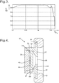
- FIG 3 shows graphically experimental test data for the variation of sound pressure level, P, in decibels, with frequency f (smoothed over 1/48 of an octave), with the earphone 10 described above.
- the earphone 10 can provide a linear response over the entire audible frequency range, without any waveform distortion. Not only is the sound generated more accurately, it has been found that the earphone 10 is more comfortable for prolonged wear, and that the users report that their ears feel fresh even after listening to the earphone 10 all day.
- the driver and the casing would typically be significantly larger, for example the driver being of diameter 25 mm, 35 mm or 50 mm, and the casing being of larger diameter, typically between 3 and 6 mm larger.
- the casing must define a restrictive duct portion equivalent to the axial bore 18, whose cross-sectional area is between 19% and 30% of the diaphragm's cross-sectional area.
- the optimum size of the restrictive duct portion can be found by experiment, but is typically between 20% and 28% of the diaphragm's cross-sectional area and so is of diameter typically between 0.45 and 0.53 times that of the diaphragm.
- the restrictive duct portion would be of diameter between 14.8 mm and 17.5 mm.
- the headphone 30 comprises a generally cylindrical aluminium casing 32 of external diameter 50 mm that defines an internal cylindrical chamber 33 of internal diameter 40.5 mm. At one end the casing 32 defines an internally threaded portion 34, and a threaded plug 35 engages this threaded portion 34 and blocks that end of the chamber 33. At the other end, the casing 32 defines an external flange 36 and an internal flange 37 defining a cylindrical aperture 38 of internal diameter 17.0 mm. The inner face of the internal flange 38 has a tapered portion 39, and also defines an internal step 40 at that end of the chamber 33.
- a ring-shaped ear cushion 42 of a soft resilient material is mounted onto the external flange 36, and comes up against the side of the user's head in use of the headphone 30.
- an acoustic driver 44 that is of a generally flat cylindrical shape, of external diameter 40 mm, but which incorporates a cylindrical magnet 45 which projects from its rear face.
- the threaded plug 35 pushes against the cylindrical magnet 45, while an O-ring 46 is compressed between the front face of the driver 44 and the internal step 40.
- the O-ring 46 is 1 mm thick, and of external diameter 40 mm, so it is adjacent to the periphery of the front face of the driver 44.
- the O-ring 46 is shown as being a separate component, it may alternatively form a projecting rim on the front face of the acoustic driver 44.
- the acoustic driver 44 includes a diaphragm (not shown), and is a dynamic driver, that is to say the diaphragm is moved by a voice coil in the field of the magnet 45.
- the diaphragm is near the front face of the driver 44, being protected by a perforated metal cover.
- the diaphragm in this case has a diameter of 35 mm.
- the driver 44 also includes a protective cover around the rear of the diaphragm, the protective cover including at least one perforation. It will be appreciated that the driver may be of a different type, for example a balanced armature type, a planar magnetic type, or an electrostatic type; and that the size of the driver and of its diaphragm may differ from that described here.
- the headphone 30 can be assembled by inserting the O-ring 46 into the cylindrical chamber 33, if it is a separate component, and then inserting the driver 44, and then introducing an electric cable through the hole 47 and connecting the electric cable to the driver 44.
- the O-ring 46 does not obstruct any of the perforations of the driver's perforated metal cover.
- the threaded plug 35 is inserted and tightened.
- the portion of the cylindrical chamber 33 behind the driver 44, that is to say between the driver 44 and the threaded plug 35, is rendered airtight by the compression of the O-ring 46.
- the depth of this airtight space is the thickness of the projecting part of the magnet 45 which in this case is 2 mm.
- the ear cushion 42 inhibits leakage of sound, so the sound is provided to the user's ear.
- the sound emerging from the front face of the driver 44 must pass through the tapering space defined by tapered portion 39 of the internal flange 37, and then through the cylindrical aperture 38.
- This cylindrical aperture 38 is clearly the narrowest part of the path followed by the sound emerging from the headphone 30 and so acts as a restrictive duct portion, so providing the same advantages as described above, of a more uniform and consistent sound output over the audible frequency range.
- the magnet 45 does not come into contact with the plug 35, and instead there is an O-ring (not shown) compressed between the rear face of the driver 44 and the face of the plug 35 near its periphery, this O-ring defining a notch or gap aligned with the hole 47 for passage of the cable.
- Embodiments of the invention define an axial rear outlet duct communicating with the rear cavity, and are described below. Many of the features are identical to those described above, and are referred to by the same reference numerals.
- an earphone 50 comprises a generally cylindrical titanium casing 12 of external diameter 7.0 mm that defines an internal cylindrical chamber 13 of internal diameter 5.1 mm.
- the casing 12 defines an internally threaded portion 14, and a threaded plug 52 engages this threaded portion 14.
- the threaded plug 52 defines an axial bore 54 of internal diameter 2.2 mm that communicates via a short tapered portion 55 with the internal cylindrical chamber 13.
- the casing 11 defines an projecting portion 16 of smaller external diameter, and this projecting portion 16 defines an axial bore 18 of internal diameter 2.2 mm that communicates via a short tapered portion 19 with the internal cylindrical chamber 13.
- the widest end of each short tapered portion 55 and 19 is 2.6 mm.
- an acoustic driver 22 which is clamped between two O-rings 23 and 24: one O-ring 23 is between the front face of the driver 22 and the internal step 20, while the other O-ring 24 is between the rear face of the driver 22 and the face of the threaded plug 52 that surrounds the short tapered portion 55.
- Each O-ring 23 and 24 is 1 mm thick, and defines a central aperture of diameter 3 mm.
- the acoustic driver 22 includes a diaphragm (not shown), and is a dynamic driver, that is to say the diaphragm is moved by a voice coil in the field of a permanent magnet.
- the diaphragm is near the front face of the driver 22, being protected by a perforated metal cover.
- the diaphragm in this case has a diameter of 4.47 mm.
- the driver 22 also includes a protective cover around the rear of the diaphragm, the protective cover including at least one perforation. It will be appreciated that the driver may be of a different type, for example a balanced armature type, a planar magnetic type or an electrostatic type; and that the size of the driver and of its diaphragm may differ from that described here.
- the earphone 50 can be assembled by inserting the O-ring 23 into the cylindrical chamber 13, and then inserting the driver 22 with the electric cable 26 projecting through the slot 25.
- the O-ring 23 does not obstruct any of the perforations of the driver's perforated metal cover.
- the O-ring 24 is then placed in position, with the electric cable 26 passing through a corresponding-sized gap cut in the O-ring 24, and the threaded plug 52 is then screwed tightly into position.
- the driver 22 is securely and firmly held between the two compressed O-rings 23 and 24.
- the O-ring 23 and the O-ring 24 may have a non-circular cross-sectional shape (in an axial section, as shown).
- they may be replaced by neoprene rubber washers or gaskets, as long as the radial width of the washer or gasket is not so great as to obstruct a significant portion of the face of the driver 22, and in this case the cross-sectional shape on each side would be square or rectangular.
- Other materials are also suitable, such as moulded silicone.
- the projecting portion 16 In use of the earphone 50 the projecting portion 16 would be provided with a foam earbud, for example a memory foam earbud (not shown), and inserted into the ear canal of the user, so that the axial bore 18 is directly connected to the user's ear canal.
- the sound emerging from the front face of the driver 22 passes through the space defined by the internal diameter of the O-ring 23, and then through the short tapered portion 19 into the axial bore 18, which is coupled to the user's ear at the other end.
- the axial bore 18 is clearly the narrowest part of the path followed by the sound emerging from the earphone 50, and so acts as a restrictive duct portion.
- the axial bore 54 is the narrowest part of the path for any sound propagating from the back of the driver 22, and so acts as a restrictive duct portion.
- the axial bores 54 and 18 are aligned with each other, as they are both coaxial with the cylindrical chamber 13, and they are of the same diameter. The provision of the two axially-aligned restrictive duct portions of the same diameter has been found to achieve an improved frequency response of the driver 22, as it can operate linearly over the entire audible range between 20 Hz and 20 kHz.
- the earphones 10 and 50 described above can be modified in various ways.
- the casing 12 may be of a different material, such as aluminium, or of a rigid non-metallic material such as an engineering plastic.
- the dimensions are also given only by way of example.
- the slope and length of the tapered portion 19 may differ from that shown; and the step 20 may be of a different size, for example being no larger than the thickness of the O-ring 23.
- the diameter of the internal cylindrical chamber 13 must be such as to fit the size of the driver 22, so with a larger driver the internal diameter of the chamber would also be correspondingly larger..
- the thickness of the O-rings 23 and 24 determines the distance between the face of the driver 22 and the corresponding end face of the internal chamber 13. If a greater distance between the face of the driver 22 and the end face of the internal chamber 13 is required, this can either be achieved by using a thicker O-ring, or by combining an O-ring 23, 24 with another ring-shaped item, for example a second O-ring, or a ring of rigid material. In each case each O-ring may be replaced by a rubber washer or gasket.
- the earphone 50 can provide a linear response over the entire audible frequency range, without any waveform distortion. Not only is the sound generated more accurately, it has been found that the earphone 50 is more comfortable for prolonged wear, and that the users report that their ears feel fresh even after listening to the earphone 50 all day; users have reported less ear fatigue even with all day use.
- the invention is equally applicable to a headphone.
- the driver and the casing would typically be significantly larger, for example the driver being of diameter 25 mm, 35 mm or 50 mm, and the casing being of larger diameter, typically between 3 and 6 mm larger.
- the casing must define a restrictive duct portion equivalent to the axial bore 54, and an aligned restrictive duct portion equivalent to the axial bore 18.
- the headphone 60 comprises a generally cylindrical aluminium casing 32 of external diameter 50 mm that defines an internal cylindrical chamber 33 of internal diameter 40.5 mm. At one end the casing 32 defines an internally threaded portion 34, and a threaded plug 62 engages this threaded portion 34. At the other end, the casing 32 defines an external flange 36 and an internal flange 37. The inner face of the internal flange 37 tapers to define a tapering duct portion 39, and also defines an internal step 40 at that end of the chamber 33. The tapering duct portion 39 communicates with a cylindrical aperture or bore 38 of internal diameter 17.0 mm. A ring-shaped ear cushion 42 of a soft resilient material is mounted onto the external flange 36, and comes up against the side of the user's head in use of the headphone 60. The cylindrical aperture or bore 38 is coaxial with the internal cylindrical chamber 33.
- the threaded plug 62 defines a cylindrical aperture or bore 64 of internal diameter 17.0 mm which communicates with a tapered portion 65 leading into the cylindrical chamber 33, and there is an annular face 66 surrounding the open end of the tapered portion 65, next to the periphery of the threaded plug 62.
- the tapered portion 65 has the same dimensions as the tapering duct portion 39; and the cylindrical aperture or bore 64 is aligned with the cylindrical aperture 38.
- an acoustic driver 44 that is of a generally flat cylindrical shape, of external diameter 40 mm, but which incorporates a cylindrical magnet 45 which projects from its rear face.
- a metal ring 67 that is also of external diameter 40 mm locates behind the acoustic driver 44, and an O-ring 68 is compressed between the rear surface of the driver 44 and the annular face 66 on the threaded plug 62.
- an O-ring 46 is compressed between the front face of the driver 44 and the internal step 40.
- the O-rings 46 and 68 are each 1 mm thick, and of external diameter 40 mm, so they are adjacent to the periphery of the cylindrical chamber 33.
- the acoustic driver 44 includes a diaphragm (not shown), and is a dynamic driver, that is to say the diaphragm is moved by a voice coil in the field of the magnet 45.
- the diaphragm is near the front face of the driver 44, being protected by a perforated metal cover.
- the diaphragm in this case has a diameter of 35 mm.
- the driver 44 also includes a protective cover around the rear of the diaphragm, the protective cover including at least one perforation.
- the driver may be of a different type, for example a balanced armature type, a planar magnetic type, or an electrostatic type; and that the size of the driver and of its diaphragm may differ from that described here.
- the headphone 60 can be assembled by inserting the O-ring 46 into the cylindrical chamber 33, if it is a separate component, and then inserting the driver 44, and then introducing an electric cable through the hole 47 and connecting the electric cable to the driver 44.
- the O-ring 46 does not obstruct any of the perforations of the driver's perforated metal cover.
- the metal ring 67 and the O-ring 68 are then inserted, the metal ring 67 defining a groove (not shown) through which the electric cable passes.
- the threaded plug 62 is then inserted and tightened so that the O-rings 46 and 68 are compressed.
- the ear cushion 42 inhibits leakage of sound, so the sound is provided to the user's ear.
- the sound emerging from the front face of the driver 44 must pass through the tapering duct portion 39 and then through the cylindrical aperture or bore 38.
- any pressure waves or sound emerging from the rear face of the driver 44 must pass through the tapered portion 65 and the cylindrical aperture or bore 64.
- the cylindrical apertures 38 and 64 are clearly the narrowest parts of the paths followed by the sound emerging from the headphone 60 and so act as restrictive duct portions, so providing the same advantages as described above, of a more uniform and consistent sound output over the audible frequency range.
- the distance between the front face of the driver 44 and the internal step 40 at the end of the cylindrical chamber 33 is determined by the thickness of the O-ring 46.
- the distance between the rear face of the periphery of the driver 44 and the annular face 66 on the threaded plug 62 is somewhat greater, because it is determined by the thickness of the combination of the metal ring 67 and the O-ring 68.
- the metal ring 67 may be omitted, so reducing the distance between the rear face of the periphery of the driver 44 and the threaded plug 62; in this modification the cylindrical magnet 45 would project slightly into the tapered portion 65.
- a second ring 67 may be inserted adjacent to the O-ring 46, so increasing the distance between the front face of the driver 44 and the end of the cylindrical chamber 33.
- the O-rings 46 and 68 may be replaced by rubber gaskets or washers. Indeed, in each case where an O-ring is described, it may be replaced by a rubber gasket or washer, for example a flat washer or gasket of a rubber-replacement material such as moulded silicone, for example of thickness typically between 0.3 mm and 5 mm, for example 0.5 mm.
- the sound quality is enhanced by the provision of the two aligned outlets of the same diameter that are coaxial with the driver: the axial bores 54 and 18 in the earphone 50, and the cylindrical apertures 64 and 38 in the headphone 60.
- the rear outlet i.e. the axial bore 54 or the cylindrical aperture 64
- a non-axial outlet leads to an asymmetrical pressure distribution over the driver, which is detrimental to the sound quality.
- the projecting portion 16 defines a sound outlet duct with a short tapered portion 19 leading to the axial bore 18.
- the angle of taper, relative to the longitudinal axis of the bore 18, is preferably between 40° and 50°, and in both these cases is 45°.
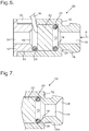
- FIG 7 shows a partial view of a casing 72 for an earphone 70, differing only from the casing 12 in having a modified projecting portion 16a, in which the short tapered portion 19 is significantly longer than shown above, although again it is at an angle of taper 45°.
- the axial bore 18 opens out into a widening portion 74 which also has a linear taper at an angle of 45° to the axis; consequently the axial bore 18 is correspondingly shorter.
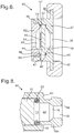
- FIG 8 shows a partial view of a casing 82 for an earphone 80, differing only from the casing 12 in having a modified projecting portion 16b, in which there is a cylindrical portion 84, followed by a short tapered portion 19 that leads to the axial bore 18; and at the outer end the axial bore 18 communicates with a short longitudinally-curved flared portion 86.
- the tapered portion 19 has a linear taper at an angle of 45° to the axis. This shape of the sound outlet duct would be equally suitable in a rear outlet duct in the plug 52 as shown in the earphone 50.
- FIG 9 there is shown an earphone 90 which in most respects is identical to the earphone 50 of figure 5 , identical features being referred to by the same reference numerals. The only difference is that instead of providing an O-ring seal 24 with a gap for the cable 26, the cable 26 is instead fed through a cable guide 92 formed of nylon. For clarity the cable 26 is not shown within the cable guide 92.
- the cable guide 92 defines a clamping ring 94 that fits coaxially within the cylindrical cavity 13 behind the driver 22, from which a stud 95 projects radially, the stud 95 fitting through the slot 25 and having a larger portion 96 which fits against the outer surface of the cylindrical casing 12.
- An inlet duct 97 extends throughout the length of the stud 95 and through the adjacent part of the clamping ring 94.
- the left-hand wall (as shown in figure 9 ) defines a projecting rounded hump 98.
- the cable 26 can extend through the inlet duct 97 and through the middle of the ring 94 to reach the rear of the driver 22, and is clamped by friction with the rounded hump 98.
- the cable guide 92 is of two mating parts: a first part 100 that defines one side (the right-hand side as shown in figure 9 ) of the inlet duct 97 and defines an arcuate portion of one face (the right-hand face as shown in figure 9 ) of the clamping ring 94, but defining a circumferential gap between ends 101 (only one of which is shown in figure 9 ) of the arcuate portion; and a second part 102 that defines the other side of the inlet duct 97, and also defines the remainder of the clamping ring 94, including a projecting part 103 which fits into the circumferential gap between the ends 101.
- the clamping ring 94 hence has a substantially continuous front face and a substantially continuous rear face.
- the wires in the cable 26 may be soldered to terminals at the rear of the driver 22.
- the cable 26 is then laid into the right-hand side (as shown in figure 9 ) of the inlet duct 97, defined by the first part 100 of the cable guide 92 so the two ends 101 of the arcuate portion project on opposite sides of the cable 26.
- the second part 102 of the cable guide 92 is then put together with the first part 100, so the projecting part 103 fits between the two ends 101 of the arcuate portion to complete the right-hand face (as shown in figure 9 ) of the clamping ring 94, and the cable 26 is then squeezed and clamped by the projecting hump 98.
- the threaded plug 52 is then screwed into the threaded portion 14 so the clamping ring 94 is compressed between the front face of the plug 52 and the rear face of the driver 22.
- the clamping ring 94 provides substantially uniform compression around the entire periphery of the rear face of the driver 22.
- the cable 26 is clamped by the hump 98 within the inlet duct 97, so tension on the cable 26 is transmitted through the cable guide 92 to the earphone 90, so the connections or soldered joints between the wires in the cable 26 and the terminals of the driver 22 are not subjected to tension.
Landscapes
- Engineering & Computer Science (AREA)
- Physics & Mathematics (AREA)
- Acoustics & Sound (AREA)
- Signal Processing (AREA)
- Manufacturing & Machinery (AREA)
- Headphones And Earphones (AREA)
Claims (13)
- Casque d'écoute ou écouteur (50) consistant en un boîtier (12) conçu pour s'adapter à l'oreille d'un utilisateur, le boîtier définissant une cavité (13) pour recevoir un amplificateur (22) et définissant également un conduit de sortie de son (18) qui communique avec une extrémité avant de la cavité pour fournir un son à l'oreille de l'utilisateur, le conduit de sortie de son (18) étant moins large qu'un diaphragme de l'amplificateur (22) et définissant une partie de conduit restrictive qui est une partie du conduit de sortie de son (18) qui a la plus petite section transversale, et le boîtier étant muni d'un élément de fermeture arrière (52), le boîtier enfermant l'amplificateur (22) avec le diaphragme au niveau d'une face avant de l'amplificateur, de sorte que l'amplificateur divise la cavité de réception d'amplificateur en une cavité arrière située derrière l'amplificateur et en une cavité avant située en face de l'amplificateur, la cavité avant communiquant avec le conduit de sortie de son (18) ; et comprenant également au moins un élément souple (23), de sorte que l'amplificateur (22) soit pincé entre un élément souple (23), en contact avec la face avant de l'amplificateur à proximité de la périphérie, et un élément arrière (24), en contact avec la face arrière de l'amplificateur, l'élément souple (23) en contact avec la face avant étant comprimé entre une face extrême (20) de la cavité avant et la face avant de l'amplificateur (22), le casque d'écoute ou l'écouteur étant caractérisé en ce que la cavité arrière définit un conduit de sortie arrière (54) qui est aligné axialement avec le conduit de sortie de son (18) et qui définit une partie de conduit restrictive arrière de même section transversale que la partie de conduit restrictive du conduit de sortie de son (18).
- Casque d'écoute ou écouteur selon la revendication 1, dans lequel l'élément arrière (24) est également un élément souple qui est en contact avec la face arrière de l'amplificateur (22) à proximité de sa périphérie.
- Casque d'écoute ou écouteur selon la revendication 1 ou 2, dans lequel les éléments souples (23, 24) sont des joints toriques ou des bagues rondes d'étanchéité.
- Casque d'écoute ou écouteur selon l'une quelconque des revendications précédentes, dans lequel l'élément de fermeture arrière (52) est connecté au boîtier par une connexion filetée (14).
- Casque d'écoute ou écouteur selon la revendication 4, dans lequel l'élément de fermeture arrière (52) s'ajuste au moins en partie dans une partie extrême de la cavité (13), et la connexion filetée comprend un filet (14) sur la paroi intérieure de cette partie extrême de la cavité.
- Casque d'écoute ou écouteur selon l'une quelconque des revendications précédentes, dans lequel le conduit de sortie de son comprend une partie de conduit conique (19) qui est plus large au niveau de l'extrémité la plus proche de l'amplificateur (22), et qui est à section décroissante vers la partie de conduit restrictive (18).
- Casque d'écoute ou écouteur selon la revendication 6, dans lequel la partie de conduit conique (19) présente un cône linéaire incliné selon un angle compris entre 40° et 50° vers l'axe longitudinal du conduit de sortie de son (18).
- Casque d'écoute ou écouteur selon l'une quelconque des revendications précédentes, dans lequel le conduit de sortie de son définit la partie de conduit restrictive avec une section transversale comprise entre 19 % et 30 % de la section transversale du diaphragme.
- Casque d'écoute ou écouteur selon l'une quelconque des revendications précédentes, dans lequel le conduit de sortie arrière (54) définit une partie plus large (55) au niveau de l'extrémité la plus proche de l'amplificateur (22), et qui est à section décroissante vers la partie de conduit restrictive (54).
- Casque d'écoute ou écouteur selon l'une quelconque des revendications précédentes, dans lequel le conduit de sortie de son (18) et le conduit de sortie arrière (54) ont le même profil longitudinal dans la direction s'éloignant de l'amplificateur (22).
- Casque d'écoute ou écouteur selon la revendication 10, dans lequel tant le conduit de sortie son que le conduit de sortie arrière ont une partie s'élargissant (74) au niveau de l'extrémité la plus éloignée de l'amplificateur (22).
- Casque d'écoute ou écouteur (90) selon l'une quelconque des revendications précédentes, dans lequel le boîtier (12) définit une cavité cylindrique (13) avec une paroi qui définit une encoche (25) pour l'entrée d'un câble destiné à être connecté à l'amplificateur, et comprenant également un guide-câble (92), le guide-câble (92) définissant un conduit d'entrée (97) qui peut se loger dans l'encoche, et une bague de serrage (94) qui s'ajuste coaxialement dans la cavité cylindrique, le guide-câble (92) comprenant deux parties d'accouplement : une première partie (100) qui définit un côté du conduit d'entrée (97) et définit une partie arquée d'une face de la bague de serrage (94) de manière à définir un espace circonférentiel entre les extrémités (101) de la partie arquée ; et une seconde partie (102) qui définit l'autre côté du conduit d'entrée (97) et définit également le reste de la bague de serrage (94), de sorte que lorsque les deux parties (100, 102) sont rapprochées, la bague de serrage (94) ait une face avant continue et une face arrière continue.
- Casque d'écoute ou écouteur selon la revendication 12, dans lequel la seconde partie (102) du guide-câble (92) définit une bague qui forme une face arrière de la bague de serrage, à partir de laquelle se projette une partie arquée (103) qui s'ajuste dans l'espace circonférentiel entre les extrémités (101) de la partie arquée de la première partie (100) du guide-câble (92).
Applications Claiming Priority (3)
| Application Number | Priority Date | Filing Date | Title |
|---|---|---|---|
| GBGB1506111.2A GB201506111D0 (en) | 2015-04-10 | 2015-04-10 | Headphone or earphone |
| GBGB1518586.1A GB201518586D0 (en) | 2015-10-20 | 2015-10-20 | Headphone or earphone |
| PCT/GB2016/050981 WO2016162681A1 (fr) | 2015-04-10 | 2016-04-07 | Casque d'écoute ou écouteur |
Publications (2)
| Publication Number | Publication Date |
|---|---|
| EP3281415A1 EP3281415A1 (fr) | 2018-02-14 |
| EP3281415B1 true EP3281415B1 (fr) | 2019-06-12 |
Family
ID=55754326
Family Applications (1)
| Application Number | Title | Priority Date | Filing Date |
|---|---|---|---|
| EP16716651.1A Active EP3281415B1 (fr) | 2015-04-10 | 2016-04-07 | Casque d'écoute ou écouteur |
Country Status (6)
| Country | Link |
|---|---|
| US (1) | US11343606B2 (fr) |
| EP (1) | EP3281415B1 (fr) |
| JP (1) | JP2018511273A (fr) |
| KR (1) | KR20170134703A (fr) |
| CN (1) | CN107873134B (fr) |
| WO (1) | WO2016162681A1 (fr) |
Families Citing this family (4)
| Publication number | Priority date | Publication date | Assignee | Title |
|---|---|---|---|---|
| GB2559313A (en) * | 2016-11-11 | 2018-08-08 | Flare Audio Tech Limited | Earphone |
| US10491975B2 (en) * | 2017-10-20 | 2019-11-26 | Bose Corporation | Acoustic transducer system |
| EP4033776A1 (fr) | 2019-05-24 | 2022-07-27 | Honeywell International Inc. | Dispositifs de protection auditive, capteurs d'exposition au bruit correspondants et boîtiers de capteurs et procédés associes |
| US11245972B2 (en) | 2019-12-06 | 2022-02-08 | Steven Hill | Ear tip device |
Family Cites Families (30)
| Publication number | Priority date | Publication date | Assignee | Title |
|---|---|---|---|---|
| JPS63200988U (fr) * | 1987-06-15 | 1988-12-23 | ||
| US5682434A (en) * | 1995-06-07 | 1997-10-28 | Interval Research Corporation | Wearable audio system with enhanced performance |
| JP4151157B2 (ja) * | 1999-05-31 | 2008-09-17 | ソニー株式会社 | イヤホン |
| JP2006246426A (ja) * | 2005-06-15 | 2006-09-14 | Kazuo Suzuki | イヤホーンアタッチメント及び該イヤホーンアタッチメントを装着したイヤホーン |
| JP4709017B2 (ja) * | 2006-01-12 | 2011-06-22 | ソニー株式会社 | イヤホン装置 |
| US8712071B2 (en) * | 2007-01-05 | 2014-04-29 | Apple Inc. | Headset electronics |
| US20080166006A1 (en) * | 2007-01-06 | 2008-07-10 | Apple Inc | Light diffuser |
| JP4921197B2 (ja) * | 2007-02-06 | 2012-04-25 | スター精密株式会社 | 挿入型イヤホン |
| US8194911B2 (en) | 2007-03-27 | 2012-06-05 | Logitech International, S.A. | Earphone integrated eartip |
| EP2187654B1 (fr) | 2007-09-07 | 2014-12-31 | Pioneer Corporation | Écouteur |
| CN102006533B (zh) | 2009-08-31 | 2014-08-27 | 富准精密工业(深圳)有限公司 | 耳机 |
| EP2306755B1 (fr) | 2009-09-03 | 2015-06-03 | AKG Acoustics GmbH | Écouteur oreillette |
| JP5666797B2 (ja) * | 2009-10-05 | 2015-02-12 | フォスター電機株式会社 | イヤホン |
| JP2011082701A (ja) * | 2009-10-05 | 2011-04-21 | Foster Electric Co Ltd | ヘッドホン |
| TWI435618B (zh) * | 2009-10-05 | 2014-04-21 | Merry Electronics Co Ltd | 具低音調節功能之耳機裝置 |
| EP2505000A2 (fr) * | 2009-11-23 | 2012-10-03 | Incus Laboratories Limited | Fabrication d'écouteurs antibruit |
| JP5671929B2 (ja) * | 2010-10-12 | 2015-02-18 | ソニー株式会社 | イヤホン、音響変換装置 |
| CN202035122U (zh) * | 2011-01-21 | 2011-11-09 | 东莞达电电子有限公司 | 一种具有现场感效果的耳机 |
| JP6136016B2 (ja) | 2012-01-30 | 2017-05-31 | パナソニックIpマネジメント株式会社 | イヤホン |
| CN202773055U (zh) * | 2012-07-31 | 2013-03-06 | 东莞达电电子有限公司 | 一种便于调整声音效果的耳机 |
| KR101558091B1 (ko) | 2014-05-23 | 2015-10-06 | 부전전자 주식회사 | 기압평형수단이 구비된 커널형 이어폰 |
| KR101423881B1 (ko) * | 2013-05-24 | 2014-07-25 | 부전전자 주식회사 | 이어폰용 스피커 유닛 및 이를 이용한 이어폰 |
| US8983108B2 (en) | 2013-07-18 | 2015-03-17 | Dexin Corporation | Ear headphone |
| US9363594B2 (en) | 2013-12-13 | 2016-06-07 | Apple Inc. | Earbud with membrane based acoustic mass loading |
| CN203661262U (zh) | 2014-01-02 | 2014-06-18 | 东莞市伟旺达电子有限公司 | 防尘耳机 |
| JP3196121U (ja) * | 2014-12-10 | 2015-02-19 | 勁剛企業有限公司 | 通気穴付きのイヤホン |
| CN104936080A (zh) * | 2015-07-07 | 2015-09-23 | 常州百富电子有限公司 | 带静音塞柱的耳塞 |
| US9794676B2 (en) * | 2016-01-12 | 2017-10-17 | Bose Corporation | Headphone |
| TWI628961B (zh) * | 2016-11-24 | 2018-07-01 | 王士俊 | 提供耳道減壓及提高自然音質之耳機及其製作方法 |
| CN110944266B (zh) * | 2019-12-13 | 2021-07-06 | 多摩电子(东莞)有限公司 | 一种基于弹簧限位的伸缩入耳式防尘耳机 |
-
2016
- 2016-04-07 US US15/562,368 patent/US11343606B2/en active Active
- 2016-04-07 KR KR1020177032213A patent/KR20170134703A/ko unknown
- 2016-04-07 WO PCT/GB2016/050981 patent/WO2016162681A1/fr active Application Filing
- 2016-04-07 JP JP2017552986A patent/JP2018511273A/ja not_active Ceased
- 2016-04-07 CN CN201680033719.2A patent/CN107873134B/zh active Active
- 2016-04-07 EP EP16716651.1A patent/EP3281415B1/fr active Active
Non-Patent Citations (1)
| Title |
|---|
| None * |
Also Published As
| Publication number | Publication date |
|---|---|
| KR20170134703A (ko) | 2017-12-06 |
| JP2018511273A (ja) | 2018-04-19 |
| WO2016162681A1 (fr) | 2016-10-13 |
| EP3281415A1 (fr) | 2018-02-14 |
| US20180288520A1 (en) | 2018-10-04 |
| CN107873134B (zh) | 2019-08-27 |
| US11343606B2 (en) | 2022-05-24 |
| CN107873134A (zh) | 2018-04-03 |
Similar Documents
| Publication | Publication Date | Title |
|---|---|---|
| JP6475844B2 (ja) | 開放型ヘッドホン | |
| JP5695703B2 (ja) | 音響チューニングメカニズムを有するイヤホン | |
| US7477756B2 (en) | Isolating deep canal fitting earphone | |
| EP2101512B1 (fr) | Ecouteur oreillette avec de multiples transducteurs | |
| US9813794B2 (en) | Noise reduction with in-ear headphone | |
| US20120148061A1 (en) | Earphone | |
| EP3281415B1 (fr) | Casque d'écoute ou écouteur | |
| US20120243726A1 (en) | Earphone | |
| JP6621166B1 (ja) | イヤーピース及びそれを用いたイヤホン | |
| JPWO2009031238A1 (ja) | イヤホン | |
| JP6754075B2 (ja) | イヤホン | |
| CN211744683U (zh) | 包括dsf通道的入耳式耳机 | |
| KR20000058143A (ko) | 입체 음향 이어폰 장치, 이어폰 및 이어폰 삽입 방법 | |
| EP3200476B1 (fr) | Casque d'ecoute | |
| JP5592622B2 (ja) | イヤホン | |
| CN113163297B (zh) | 音频装置以及智能头戴设备 | |
| JP6863687B2 (ja) | イヤホン | |
| KR20160061711A (ko) | 이어폰 | |
| CN106454591B (zh) | 耳机 | |
| JP7320316B1 (ja) | オープン型イヤホン | |
| KR20160046146A (ko) | 마이크로 스피커 |
Legal Events
| Date | Code | Title | Description |
|---|---|---|---|
| STAA | Information on the status of an ep patent application or granted ep patent |
Free format text: STATUS: THE INTERNATIONAL PUBLICATION HAS BEEN MADE |
|
| PUAI | Public reference made under article 153(3) epc to a published international application that has entered the european phase |
Free format text: ORIGINAL CODE: 0009012 |
|
| STAA | Information on the status of an ep patent application or granted ep patent |
Free format text: STATUS: REQUEST FOR EXAMINATION WAS MADE |
|
| 17P | Request for examination filed |
Effective date: 20171110 |
|
| AK | Designated contracting states |
Kind code of ref document: A1 Designated state(s): AL AT BE BG CH CY CZ DE DK EE ES FI FR GB GR HR HU IE IS IT LI LT LU LV MC MK MT NL NO PL PT RO RS SE SI SK SM TR |
|
| AX | Request for extension of the european patent |
Extension state: BA ME |
|
| DAV | Request for validation of the european patent (deleted) | ||
| DAX | Request for extension of the european patent (deleted) | ||
| GRAP | Despatch of communication of intention to grant a patent |
Free format text: ORIGINAL CODE: EPIDOSNIGR1 |
|
| STAA | Information on the status of an ep patent application or granted ep patent |
Free format text: STATUS: GRANT OF PATENT IS INTENDED |
|
| INTG | Intention to grant announced |
Effective date: 20181115 |
|
| RAP1 | Party data changed (applicant data changed or rights of an application transferred) |
Owner name: FLARE AUDIO TECHNOLOGIES LIMITED |
|
| GRAS | Grant fee paid |
Free format text: ORIGINAL CODE: EPIDOSNIGR3 |
|
| GRAA | (expected) grant |
Free format text: ORIGINAL CODE: 0009210 |
|
| STAA | Information on the status of an ep patent application or granted ep patent |
Free format text: STATUS: THE PATENT HAS BEEN GRANTED |
|
| AK | Designated contracting states |
Kind code of ref document: B1 Designated state(s): AL AT BE BG CH CY CZ DE DK EE ES FI FR GB GR HR HU IE IS IT LI LT LU LV MC MK MT NL NO PL PT RO RS SE SI SK SM TR |
|
| REG | Reference to a national code |
Ref country code: GB Ref legal event code: FG4D |
|
| REG | Reference to a national code |
Ref country code: CH Ref legal event code: EP |
|
| REG | Reference to a national code |
Ref country code: AT Ref legal event code: REF Ref document number: 1144143 Country of ref document: AT Kind code of ref document: T Effective date: 20190615 |
|
| REG | Reference to a national code |
Ref country code: DE Ref legal event code: R096 Ref document number: 602016015170 Country of ref document: DE |
|
| REG | Reference to a national code |
Ref country code: IE Ref legal event code: FG4D |
|
| REG | Reference to a national code |
Ref country code: NL Ref legal event code: FP |
|
| REG | Reference to a national code |
Ref country code: LT Ref legal event code: MG4D |
|
| PG25 | Lapsed in a contracting state [announced via postgrant information from national office to epo] |
Ref country code: AL Free format text: LAPSE BECAUSE OF FAILURE TO SUBMIT A TRANSLATION OF THE DESCRIPTION OR TO PAY THE FEE WITHIN THE PRESCRIBED TIME-LIMIT Effective date: 20190612 Ref country code: LT Free format text: LAPSE BECAUSE OF FAILURE TO SUBMIT A TRANSLATION OF THE DESCRIPTION OR TO PAY THE FEE WITHIN THE PRESCRIBED TIME-LIMIT Effective date: 20190612 Ref country code: FI Free format text: LAPSE BECAUSE OF FAILURE TO SUBMIT A TRANSLATION OF THE DESCRIPTION OR TO PAY THE FEE WITHIN THE PRESCRIBED TIME-LIMIT Effective date: 20190612 Ref country code: SE Free format text: LAPSE BECAUSE OF FAILURE TO SUBMIT A TRANSLATION OF THE DESCRIPTION OR TO PAY THE FEE WITHIN THE PRESCRIBED TIME-LIMIT Effective date: 20190612 Ref country code: HR Free format text: LAPSE BECAUSE OF FAILURE TO SUBMIT A TRANSLATION OF THE DESCRIPTION OR TO PAY THE FEE WITHIN THE PRESCRIBED TIME-LIMIT Effective date: 20190612 Ref country code: NO Free format text: LAPSE BECAUSE OF FAILURE TO SUBMIT A TRANSLATION OF THE DESCRIPTION OR TO PAY THE FEE WITHIN THE PRESCRIBED TIME-LIMIT Effective date: 20190912 |
|
| PG25 | Lapsed in a contracting state [announced via postgrant information from national office to epo] |
Ref country code: LV Free format text: LAPSE BECAUSE OF FAILURE TO SUBMIT A TRANSLATION OF THE DESCRIPTION OR TO PAY THE FEE WITHIN THE PRESCRIBED TIME-LIMIT Effective date: 20190612 Ref country code: GR Free format text: LAPSE BECAUSE OF FAILURE TO SUBMIT A TRANSLATION OF THE DESCRIPTION OR TO PAY THE FEE WITHIN THE PRESCRIBED TIME-LIMIT Effective date: 20190913 Ref country code: RS Free format text: LAPSE BECAUSE OF FAILURE TO SUBMIT A TRANSLATION OF THE DESCRIPTION OR TO PAY THE FEE WITHIN THE PRESCRIBED TIME-LIMIT Effective date: 20190612 Ref country code: BG Free format text: LAPSE BECAUSE OF FAILURE TO SUBMIT A TRANSLATION OF THE DESCRIPTION OR TO PAY THE FEE WITHIN THE PRESCRIBED TIME-LIMIT Effective date: 20190912 |
|
| REG | Reference to a national code |
Ref country code: AT Ref legal event code: MK05 Ref document number: 1144143 Country of ref document: AT Kind code of ref document: T Effective date: 20190612 |
|
| PG25 | Lapsed in a contracting state [announced via postgrant information from national office to epo] |
Ref country code: PT Free format text: LAPSE BECAUSE OF FAILURE TO SUBMIT A TRANSLATION OF THE DESCRIPTION OR TO PAY THE FEE WITHIN THE PRESCRIBED TIME-LIMIT Effective date: 20191014 Ref country code: AT Free format text: LAPSE BECAUSE OF FAILURE TO SUBMIT A TRANSLATION OF THE DESCRIPTION OR TO PAY THE FEE WITHIN THE PRESCRIBED TIME-LIMIT Effective date: 20190612 Ref country code: RO Free format text: LAPSE BECAUSE OF FAILURE TO SUBMIT A TRANSLATION OF THE DESCRIPTION OR TO PAY THE FEE WITHIN THE PRESCRIBED TIME-LIMIT Effective date: 20190612 Ref country code: SK Free format text: LAPSE BECAUSE OF FAILURE TO SUBMIT A TRANSLATION OF THE DESCRIPTION OR TO PAY THE FEE WITHIN THE PRESCRIBED TIME-LIMIT Effective date: 20190612 Ref country code: EE Free format text: LAPSE BECAUSE OF FAILURE TO SUBMIT A TRANSLATION OF THE DESCRIPTION OR TO PAY THE FEE WITHIN THE PRESCRIBED TIME-LIMIT Effective date: 20190612 |
|
| PG25 | Lapsed in a contracting state [announced via postgrant information from national office to epo] |
Ref country code: ES Free format text: LAPSE BECAUSE OF FAILURE TO SUBMIT A TRANSLATION OF THE DESCRIPTION OR TO PAY THE FEE WITHIN THE PRESCRIBED TIME-LIMIT Effective date: 20190612 Ref country code: IS Free format text: LAPSE BECAUSE OF FAILURE TO SUBMIT A TRANSLATION OF THE DESCRIPTION OR TO PAY THE FEE WITHIN THE PRESCRIBED TIME-LIMIT Effective date: 20191012 Ref country code: SM Free format text: LAPSE BECAUSE OF FAILURE TO SUBMIT A TRANSLATION OF THE DESCRIPTION OR TO PAY THE FEE WITHIN THE PRESCRIBED TIME-LIMIT Effective date: 20190612 |
|
| REG | Reference to a national code |
Ref country code: DE Ref legal event code: R097 Ref document number: 602016015170 Country of ref document: DE |
|
| PG25 | Lapsed in a contracting state [announced via postgrant information from national office to epo] |
Ref country code: TR Free format text: LAPSE BECAUSE OF FAILURE TO SUBMIT A TRANSLATION OF THE DESCRIPTION OR TO PAY THE FEE WITHIN THE PRESCRIBED TIME-LIMIT Effective date: 20190612 |
|
| PLBE | No opposition filed within time limit |
Free format text: ORIGINAL CODE: 0009261 |
|
| STAA | Information on the status of an ep patent application or granted ep patent |
Free format text: STATUS: NO OPPOSITION FILED WITHIN TIME LIMIT |
|
| PG25 | Lapsed in a contracting state [announced via postgrant information from national office to epo] |
Ref country code: DK Free format text: LAPSE BECAUSE OF FAILURE TO SUBMIT A TRANSLATION OF THE DESCRIPTION OR TO PAY THE FEE WITHIN THE PRESCRIBED TIME-LIMIT Effective date: 20190612 Ref country code: PL Free format text: LAPSE BECAUSE OF FAILURE TO SUBMIT A TRANSLATION OF THE DESCRIPTION OR TO PAY THE FEE WITHIN THE PRESCRIBED TIME-LIMIT Effective date: 20190612 |
|
| 26N | No opposition filed |
Effective date: 20200313 |
|
| PG25 | Lapsed in a contracting state [announced via postgrant information from national office to epo] |
Ref country code: IS Free format text: LAPSE BECAUSE OF FAILURE TO SUBMIT A TRANSLATION OF THE DESCRIPTION OR TO PAY THE FEE WITHIN THE PRESCRIBED TIME-LIMIT Effective date: 20200224 Ref country code: SI Free format text: LAPSE BECAUSE OF FAILURE TO SUBMIT A TRANSLATION OF THE DESCRIPTION OR TO PAY THE FEE WITHIN THE PRESCRIBED TIME-LIMIT Effective date: 20190612 |
|
| PG2D | Information on lapse in contracting state deleted |
Ref country code: IS |
|
| PG25 | Lapsed in a contracting state [announced via postgrant information from national office to epo] |
Ref country code: CZ Free format text: LAPSE BECAUSE OF NON-PAYMENT OF DUE FEES Effective date: 20200407 |
|
| REG | Reference to a national code |
Ref country code: DE Ref legal event code: R119 Ref document number: 602016015170 Country of ref document: DE |
|
| PG25 | Lapsed in a contracting state [announced via postgrant information from national office to epo] |
Ref country code: MC Free format text: LAPSE BECAUSE OF FAILURE TO SUBMIT A TRANSLATION OF THE DESCRIPTION OR TO PAY THE FEE WITHIN THE PRESCRIBED TIME-LIMIT Effective date: 20190612 |
|
| REG | Reference to a national code |
Ref country code: CH Ref legal event code: PL |
|
| REG | Reference to a national code |
Ref country code: NL Ref legal event code: MM Effective date: 20200501 |
|
| PG25 | Lapsed in a contracting state [announced via postgrant information from national office to epo] |
Ref country code: LU Free format text: LAPSE BECAUSE OF NON-PAYMENT OF DUE FEES Effective date: 20200407 Ref country code: CH Free format text: LAPSE BECAUSE OF NON-PAYMENT OF DUE FEES Effective date: 20200430 Ref country code: FR Free format text: LAPSE BECAUSE OF NON-PAYMENT OF DUE FEES Effective date: 20200430 Ref country code: LI Free format text: LAPSE BECAUSE OF NON-PAYMENT OF DUE FEES Effective date: 20200430 Ref country code: DE Free format text: LAPSE BECAUSE OF NON-PAYMENT OF DUE FEES Effective date: 20201103 |
|
| REG | Reference to a national code |
Ref country code: BE Ref legal event code: MM Effective date: 20200430 |
|
| PG25 | Lapsed in a contracting state [announced via postgrant information from national office to epo] |
Ref country code: BE Free format text: LAPSE BECAUSE OF NON-PAYMENT OF DUE FEES Effective date: 20200430 |
|
| PG25 | Lapsed in a contracting state [announced via postgrant information from national office to epo] |
Ref country code: NL Free format text: LAPSE BECAUSE OF NON-PAYMENT OF DUE FEES Effective date: 20200501 |
|
| PG25 | Lapsed in a contracting state [announced via postgrant information from national office to epo] |
Ref country code: IE Free format text: LAPSE BECAUSE OF NON-PAYMENT OF DUE FEES Effective date: 20200407 |
|
| PG25 | Lapsed in a contracting state [announced via postgrant information from national office to epo] |
Ref country code: IT Free format text: LAPSE BECAUSE OF NON-PAYMENT OF DUE FEES Effective date: 20200407 |
|
| PG25 | Lapsed in a contracting state [announced via postgrant information from national office to epo] |
Ref country code: MT Free format text: LAPSE BECAUSE OF FAILURE TO SUBMIT A TRANSLATION OF THE DESCRIPTION OR TO PAY THE FEE WITHIN THE PRESCRIBED TIME-LIMIT Effective date: 20190612 Ref country code: CY Free format text: LAPSE BECAUSE OF FAILURE TO SUBMIT A TRANSLATION OF THE DESCRIPTION OR TO PAY THE FEE WITHIN THE PRESCRIBED TIME-LIMIT Effective date: 20190612 |
|
| PG25 | Lapsed in a contracting state [announced via postgrant information from national office to epo] |
Ref country code: MK Free format text: LAPSE BECAUSE OF FAILURE TO SUBMIT A TRANSLATION OF THE DESCRIPTION OR TO PAY THE FEE WITHIN THE PRESCRIBED TIME-LIMIT Effective date: 20190612 |
|
| PGFP | Annual fee paid to national office [announced via postgrant information from national office to epo] |
Ref country code: GB Payment date: 20240502 Year of fee payment: 9 |