EP3280613B1 - Longitudinal adjustment mechanism, vehicle seat - Google Patents
Longitudinal adjustment mechanism, vehicle seat Download PDFInfo
- Publication number
- EP3280613B1 EP3280613B1 EP16712936.0A EP16712936A EP3280613B1 EP 3280613 B1 EP3280613 B1 EP 3280613B1 EP 16712936 A EP16712936 A EP 16712936A EP 3280613 B1 EP3280613 B1 EP 3280613B1
- Authority
- EP
- European Patent Office
- Prior art keywords
- seat rail
- blocking element
- seat
- longitudinal adjuster
- adjuster according
- Prior art date
- Legal status (The legal status is an assumption and is not a legal conclusion. Google has not performed a legal analysis and makes no representation as to the accuracy of the status listed.)
- Active
Links
Images


Classifications
-
- B—PERFORMING OPERATIONS; TRANSPORTING
- B60—VEHICLES IN GENERAL
- B60N—SEATS SPECIALLY ADAPTED FOR VEHICLES; VEHICLE PASSENGER ACCOMMODATION NOT OTHERWISE PROVIDED FOR
- B60N2/00—Seats specially adapted for vehicles; Arrangement or mounting of seats in vehicles
- B60N2/02—Seats specially adapted for vehicles; Arrangement or mounting of seats in vehicles the seat or part thereof being movable, e.g. adjustable
- B60N2/04—Seats specially adapted for vehicles; Arrangement or mounting of seats in vehicles the seat or part thereof being movable, e.g. adjustable the whole seat being movable
- B60N2/06—Seats specially adapted for vehicles; Arrangement or mounting of seats in vehicles the seat or part thereof being movable, e.g. adjustable the whole seat being movable slidable
-
- B—PERFORMING OPERATIONS; TRANSPORTING
- B60—VEHICLES IN GENERAL
- B60N—SEATS SPECIALLY ADAPTED FOR VEHICLES; VEHICLE PASSENGER ACCOMMODATION NOT OTHERWISE PROVIDED FOR
- B60N2/00—Seats specially adapted for vehicles; Arrangement or mounting of seats in vehicles
- B60N2/02—Seats specially adapted for vehicles; Arrangement or mounting of seats in vehicles the seat or part thereof being movable, e.g. adjustable
- B60N2/04—Seats specially adapted for vehicles; Arrangement or mounting of seats in vehicles the seat or part thereof being movable, e.g. adjustable the whole seat being movable
- B60N2/06—Seats specially adapted for vehicles; Arrangement or mounting of seats in vehicles the seat or part thereof being movable, e.g. adjustable the whole seat being movable slidable
- B60N2/07—Slide construction
- B60N2/0702—Slide construction characterised by its cross-section
- B60N2/0705—Slide construction characterised by its cross-section omega-shaped
-
- B—PERFORMING OPERATIONS; TRANSPORTING
- B60—VEHICLES IN GENERAL
- B60N—SEATS SPECIALLY ADAPTED FOR VEHICLES; VEHICLE PASSENGER ACCOMMODATION NOT OTHERWISE PROVIDED FOR
- B60N2/00—Seats specially adapted for vehicles; Arrangement or mounting of seats in vehicles
- B60N2/02—Seats specially adapted for vehicles; Arrangement or mounting of seats in vehicles the seat or part thereof being movable, e.g. adjustable
- B60N2/04—Seats specially adapted for vehicles; Arrangement or mounting of seats in vehicles the seat or part thereof being movable, e.g. adjustable the whole seat being movable
- B60N2/06—Seats specially adapted for vehicles; Arrangement or mounting of seats in vehicles the seat or part thereof being movable, e.g. adjustable the whole seat being movable slidable
- B60N2/08—Seats specially adapted for vehicles; Arrangement or mounting of seats in vehicles the seat or part thereof being movable, e.g. adjustable the whole seat being movable slidable characterised by the locking device
- B60N2/0812—Location of the latch
- B60N2/0818—Location of the latch inside the rail
-
- B—PERFORMING OPERATIONS; TRANSPORTING
- B60—VEHICLES IN GENERAL
- B60N—SEATS SPECIALLY ADAPTED FOR VEHICLES; VEHICLE PASSENGER ACCOMMODATION NOT OTHERWISE PROVIDED FOR
- B60N2/00—Seats specially adapted for vehicles; Arrangement or mounting of seats in vehicles
- B60N2/02—Seats specially adapted for vehicles; Arrangement or mounting of seats in vehicles the seat or part thereof being movable, e.g. adjustable
- B60N2/04—Seats specially adapted for vehicles; Arrangement or mounting of seats in vehicles the seat or part thereof being movable, e.g. adjustable the whole seat being movable
- B60N2/06—Seats specially adapted for vehicles; Arrangement or mounting of seats in vehicles the seat or part thereof being movable, e.g. adjustable the whole seat being movable slidable
- B60N2/08—Seats specially adapted for vehicles; Arrangement or mounting of seats in vehicles the seat or part thereof being movable, e.g. adjustable the whole seat being movable slidable characterised by the locking device
- B60N2/0831—Movement of the latch
- B60N2/0862—Movement of the latch sliding
- B60N2/0875—Movement of the latch sliding in a vertical direction
-
- B—PERFORMING OPERATIONS; TRANSPORTING
- B60—VEHICLES IN GENERAL
- B60N—SEATS SPECIALLY ADAPTED FOR VEHICLES; VEHICLE PASSENGER ACCOMMODATION NOT OTHERWISE PROVIDED FOR
- B60N2/00—Seats specially adapted for vehicles; Arrangement or mounting of seats in vehicles
- B60N2/02—Seats specially adapted for vehicles; Arrangement or mounting of seats in vehicles the seat or part thereof being movable, e.g. adjustable
- B60N2/04—Seats specially adapted for vehicles; Arrangement or mounting of seats in vehicles the seat or part thereof being movable, e.g. adjustable the whole seat being movable
- B60N2/12—Seats specially adapted for vehicles; Arrangement or mounting of seats in vehicles the seat or part thereof being movable, e.g. adjustable the whole seat being movable slidable and tiltable
- B60N2/123—Seats specially adapted for vehicles; Arrangement or mounting of seats in vehicles the seat or part thereof being movable, e.g. adjustable the whole seat being movable slidable and tiltable and provided with memory locks
-
- B—PERFORMING OPERATIONS; TRANSPORTING
- B60—VEHICLES IN GENERAL
- B60N—SEATS SPECIALLY ADAPTED FOR VEHICLES; VEHICLE PASSENGER ACCOMMODATION NOT OTHERWISE PROVIDED FOR
- B60N2/00—Seats specially adapted for vehicles; Arrangement or mounting of seats in vehicles
- B60N2/02—Seats specially adapted for vehicles; Arrangement or mounting of seats in vehicles the seat or part thereof being movable, e.g. adjustable
- B60N2/20—Seats specially adapted for vehicles; Arrangement or mounting of seats in vehicles the seat or part thereof being movable, e.g. adjustable the back-rest being tiltable, e.g. to permit easy access
Definitions
- the invention relates to a longitudinal adjuster for a longitudinally adjustable vehicle seat with the features of the preamble of claim 1, as well as a vehicle seat.
- the easy entry system can be actuated by an unlocking lever which is usually arranged on a backrest of the vehicle seat, as a result of which the backrest of the vehicle seat pivots out of an entry area. If the vehicle seat is arranged on rails, the vehicle seat can additionally or alternatively be slidable out of the entry area in the direction of travel when the unlocking lever is actuated.
- an easy-entry adjustment device for a vehicle seat enables the vehicle seat to be adjusted between a use position and an easy-entry position. Such adjustability is particularly advantageous for vehicles that have only one door per side of the vehicle.
- both a backrest fitting of the adjustment device and a longitudinal seat lock of the adjustment device are released. Releasing the backrest fitting enables the seat back of the vehicle seat to be pivoted forward in the direction of a seat part of the vehicle seat, while releasing the longitudinal seat lock enables the entire vehicle seat to be advanced in the direction of travel. A vehicle occupant thus gains access to the rear seats of the vehicle.
- a longitudinal seat adjustment with a pair of rails consisting of an upper rail and a lower rail and a lock for preventing movement from the upper rail to the lower rail is generally known.
- the lock is designed as a locking plate which is connected to the top rail by means of a spring and at the same time has a holder for one end of the spring.
- a longitudinal adjuster for a vehicle seat with entry adjustment which has a memory device for detecting a relative longitudinal displacement of the seat.
- the memory device is arranged in the interior of an installation space formed between a first seat rail and a second seat rail and is connected to the first seat rail.
- the memory device has a locking element which can be brought into engagement with the second seat rail and which, when the locking function is actuated, introduces all the forces acting on the locking element into the memory device.
- a device for automatically locking a component when it reaches a previously occupied and in the meantime left to assume a different functional position setting position, the setting position being provided to be changeable on an adjustment range of the component, and the automatic locking of the component can be brought about by means of a gear mechanism and a locking element , wherein the gear mechanism transmits the movement of the component from its setting position to its functional position and back to the locking element by means of a variable transmission.
- the invention is based on the object of improving a longitudinal adjuster of the type mentioned at the beginning, and to provide a vehicle seat with a longitudinal adjuster according to the invention.
- a longitudinal adjuster for a longitudinally adjustable vehicle seat has a pair of rails with a structurally fixed second seat rail, in particular a lower rail, and a seat-fixed first seat rail, in particular an upper rail, guided in this second seat rail. Furthermore, the longitudinal adjuster has a memory device which is set up to store the position of the first seat rail, which is fixed to the seat, in relation to the structurally fixed second seat rail, as well as a locking element guided in the first seat rail to block the movement of the first seat rail relative to the second seat rail.
- the first seat rail is blocked relative to the second seat rail by means of the locking element, in that the locking element is brought into engagement with a toothing and / or a hole pattern of the second seat rail.
- the locking element can be actuated by means of the memory device.
- the memory device is located outside of the flow of force between the first seat rail and the second seat rail, while the locking element for blocking the first seat rail in engagement with a toothing and / or a hole pattern of the second seat rail is in the flow of force.
- the longitudinal adjuster has at least one further locking element which is set up to lock the first seat rail, which is fixed to the seat, in relation to the second seat rail, which is fixed to the structure.
- the locking element is only set up to block a movement of the first seat rail relative to the second seat rail when the stored memory position is reached, while the locking element is used in a manner known per se to set a longitudinal seat position and to accommodate at a frontal impact occurring forces is set up.
- the first seat rail When the stored memory position is reached, the first seat rail is blocked with the second seat rail by means of the locking element. As a result of the movement of the first seat rail relative to the second seat rail, the abruptly engaging blocking means that sometimes very high forces have to be absorbed.
- a flow of force desired here runs from the first seat rail via the one in the first seat rail guided locking element on a toothing or a hole pattern of the second seat rail. Because the memory device or only parts of the memory device are located outside the flow of forces, they do not have to be designed to absorb high forces in the longitudinal direction of the pair of rails. Consequently, according to the invention, the possibility of manufacturing the memory device with correspondingly thinner materials opens up, which only have to meet the lower strength requirements. As a result, the memory device can, for example, be made more compact in terms of structural volume and accordingly also lighter.
- the locking element of the longitudinal adjuster can be arranged in the first seat rail and, in particular, be guided in a recess in the first seat rail. Furthermore, the recess in the first seat rail can have an upper stop and a lower stop to limit the path for the locking element. In this case, the locking element resting against the lower stop can correspond to the release position. Furthermore, if the blocking element rests against the upper stop, the blocking position can correspond.
- the locking element can have a slope.
- the incline can interact with a contour of the toothing that is rounded off in some areas.
- the memory device for actuating the locking element can have an actuating arm which is operatively connected to a gear and is movable relative to the gear.
- the locking element can be automatically transferred into the blocking position or the release position by means of a return spring.
- the return spring can in particular be designed as a tension spring or as a compression spring.
- the return spring is designed in the form of a compression spring which moves the locking element automatically into the release position
- the actuating arm of the memory device can act on the locking element, preferably from below, against the compressive force of the return spring.
- the actuating arm of the memory device can act on the locking element, preferably from above, against the tensile force of the return spring. Furthermore, when the memory position is reached again, the actuating arm can release the locking element from the release position. Furthermore, a fixed connection can be provided between each end section of the return spring and the first seat rail and the locking element.
- the object is achieved according to the invention by a vehicle seat with at least one longitudinal adjuster according to the preceding description.
- a longitudinal direction x runs largely horizontally and preferably parallel to a vehicle longitudinal direction which corresponds to the normal direction of travel of the vehicle.
- a transverse direction y running perpendicular to the longitudinal direction x is also oriented horizontally in the vehicle and runs parallel to a transverse direction of the vehicle.
- a vertical direction z runs perpendicular to the longitudinal direction x and perpendicular to the transverse direction y. In the case of a vehicle seat 1 installed in the vehicle, the vertical direction z runs parallel to a vertical axis of the vehicle.
- the position information and direction information used such as front, rear, top and bottom refer to a line of sight of an occupant sitting in the vehicle seat 1 in a normal sitting position, the vehicle seat 1 being installed in the vehicle, in a position of use suitable for passenger transport with an upright backrest and how Usually aligned in the direction of travel.
- the vehicle seat 1 can, however, also be installed in a different orientation, for example transversely to the direction of travel.
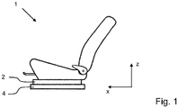
- the in Fig. 1 The vehicle seat 1 shown is mounted in a position of use with the backrest upright on a longitudinal adjuster according to the invention.
- the longitudinal adjuster according to the invention has at least one, usually two pairs of seat rails, each of which comprises a first seat rail 2 and a second seat rail 4.
- the first seat rail 2 can be displaced in the longitudinal direction relative to the second seat rail 4.
- the vehicle seat 1 is firmly connected to the first seat rail 2.
- the second seat rail 4 is usually provided with a vehicle floor (not shown) and / or a vehicle structure connected.
- the vehicle seat 1, together with the first seat rail 2, which is fixed to the seat, can be displaced in the longitudinal direction x relative to the second seat rail 4, which is fixed to the structure.
- the vehicle seat preferably has two longitudinal adjusters oriented essentially symmetrically to a central axis.
- Fig. 2 a schematic representation of a top view of a pair of rails with a first seat rail 2 and second seat rail 4 is shown.
- the pair of rails consists of a second seat rail 4 connectable to the vehicle structure and a first seat rail 2 fixed to the seat.
- the first seat rail 2 and the second seat rail 4 engage around one another in a manner known per se and are slidably mounted on one another in the longitudinal direction x.
- the view serves according to Fig. 2 the marking of the cutting planes, which in the Figures 3 to 5 are shown.
- Fig. 3 shows a longitudinal section AA of the pair of rails according to Fig. 2 .
- the second seat rail 4 has a toothing 8, with which the locking element 14 can be brought into engagement.
- the locking element 14 is located as shown in FIG Fig. 3 in the blocking position, that means in engagement with the toothing 8 of the second seat rail 4.
- the release position of the locking element 14, in which the locking element 14 is in the recess 6 of the first seat rail 2 and out of engagement with the toothing 8 of the second seat rail 4, is shown in dashed lines.
- the locking element 14 When the locking element 14 is held in the release position, it preferably rests against a lower stop 12, the lower stop 12 corresponding to a lower limit of the recess 6 in the installation direction of the first seat rail 2, in which the locking element 14 is guided.
- the locking element 14 has a slope 16
- this slope 16 is used to facilitate the disengagement of the locking element 14 from the teeth 8 of the second seat rail 4.
- the slope 16 acts relatively in the case of a forward movement of the first seat rail 2 indicated by the arrow 20 to the second seat rail 4, with the partially rounded contour 8a of the toothing 8, so that the locking element 14 is driven out of the toothing 8 more quickly at the beginning of the forward movement before a corresponding completed movement of the locking element 14 can be effected by an actuating arm of a memory device.
- Fig. 4 is a longitudinal section CC of the pair of rails according to Fig. 2 shown.
- the blocking element 14 rests against an upper stop 10 of the recess 6 of the first seat rail 2 in the blocking position and its movement in the vertical direction z is limited.
- the locking element 14 In the release position shown in dashed lines, the locking element 14 is in contact with the lower stop 12 of the recess 6 of the first seat rail 2.
- Fig. 5 further shows a cross section DD of the pair of rails according to FIG Fig. 2 .
- the locking element 14 is initially shown in its blocking position in engagement with the toothing 8 of the second seat rail 4.
- the release position in which the locking element 14 is out of engagement with the second seat rail 4 is again shown in dashed lines.
- the restoring spring 18 can in the present case be designed as a tension spring or as a compression spring, depending on whether the locking element 14 is to independently assume the blocking position or the release position.
- actuating arm of the memory device engages from below against the compressive force of the return spring 18 and moves the locking element 14 into the blocking position when the memory position is reached.
- the return spring 18 in the form of a tension spring, which moves the locking element 14 automatically into the blocking position
- an actuating arm not shown, of the memory device from above, against the tensile force of the return spring 18 on the locking element 14 attacks.
- the actuating arm first moves the locking element 14 when leaving the memory position in the release position and holds it in this position.
- the actuating arm releases the locking element 14 from the release position, whereby the return spring 18 releases the locking element 14 moved back into the blocking position.
- a fixed connection is provided between each end section of the return spring 18 and each of the first seat rail 2 and the locking element 14.
- the respective end section of the return spring 18 can be inserted, for example, into a hook provided in the first seat rail 2 and / or on the locking element 14.
- the locking element 14 is arranged in the first seat rail 2 and guided in a recess 6 in the first seat rail 2.
- the recess 6 of the first seat rail 2 has an upper stop 10 and a lower stop 12 to limit the travel of the locking element 14. Between these stops 10, 12, the blocking element 14 is movably guided in the recess 6 in the vertical direction z.
- Fig. 6 shows a perspective illustration of a first possible embodiment of a memory device 22 for actuating the locking element 14.
- Fig. 6 shows a housing 26, which is designed to be open in the direction of the locking element 14, so that an actuating arm 24 of the memory device 22 can engage the locking element 14 from below and control it in an upward movement.
- the actuation from below corresponds to an embodiment of the return spring 18 as a compression spring, which drives the locking element 14 into the release position under spring load and the locking element 14 can be brought into the blocking position by actuation by means of the actuating arm 24 against the force of the return spring 18.
- a second axis 31b and a third axis 31c mounted in the housing 26 are shown in this illustration, on each of which gearwheels, not shown, of a transmission of the memory device are mounted.
- the transmission 30 of the memory device 22 also has a first axis 31a that cannot be seen from the outside.
- Fig. 7 is a cross-sectional view of a longitudinal adjuster according to the invention with a memory device 22 is shown.
- Fig. 7 shows a memory device 22 assigned to the first seat rail 2 and interacting with the second seat rail 4, which is set up to store a set memory position which is determined by a longitudinal displacement of the Leave vehicle seat 1 and can be taken again.
- the memory device 22 is connected to the first seat rail 2, preferably by means of a screw connection between the housing 26 and the first seat rail 2.
- a gear 30 arranged in a housing 26 of the memory device 22, in particular a first toothed wheel 32a of the gear 30, interacts with a rack 28 arranged in a bottom area of the second seat rail 4 which is fixed to the structure.
- FIG. 7 A blocking element 14 is also shown, which is between a blocking position in which the blocking element 14 is in engagement with a toothing 8 of the second seat rail 4 as shown, and a release position in which the blocking element 14 (shown in dashed lines) is out of engagement with the second seat rail 4 is movable.
- the locking element 14 is supported and guided in a recess 6 provided in the first seat rail 2.
- the movement of the locking element 14 in the vertical direction z in the recess 6 of the first seat rail 2 is limited by an upper stop 10 and a lower stop 12.
- the locking element 14 is supported on an upper section of the first seat rail 2 by means of a return spring 18 (cannot be seen for reasons of illustration technology).
- the restoring spring 18 can in particular be designed as a compression spring or as a tension spring, depending on whether the locking element 14 is to assume the blocking position or the release position in a spring-loaded manner.
- the memory device 22 has an actuating arm 24 which is operatively connected to the gear 30 and is movable relative to the gear.
- the transmission 30 exerts a control torque on the actuating arm 24, on the basis of which the actuating arm 24 controls the locking element 14.
- control can generally be understood to mean that a change in the resulting force acting on the locking element 14 is achieved by means of a movement of the actuating arm 24.
Description
Die Erfindung betrifft einen Längseinsteller für einen längseinstellbaren Fahrzeugsitz mit den Merkmalen des Oberbegriffs des Anspruchs 1, sowie einen Fahrzeugsitz.The invention relates to a longitudinal adjuster for a longitudinally adjustable vehicle seat with the features of the preamble of
Im Stand der Technik sind verschiedene Easy-Entry-Systeme bekannt, welche einen erleichterten Einstieg in eine zweite Sitzreihe eines Fahrzeuges ermöglichen. Das Easy-Entry-System ist durch einen Entriegelungshebel, welcher üblicherweise an einer Rückenlehne des Fahrzeugsitzes angeordnet ist, betätigbar, wodurch die Rückenlehne des Fahrzeugsitzes aus einem Einstiegsbereich schwenkt. Ist der Fahrzeugsitz auf Schienen angeordnet, kann der Fahrzeugsitz bei Betätigung des Entriegelungshebels zusätzlich oder alternativ in Fahrtrichtung aus dem Einstiegsbereich heraus verschiebbar sein.Various easy entry systems are known in the prior art, which enable easier entry into a second row of seats in a vehicle. The easy entry system can be actuated by an unlocking lever which is usually arranged on a backrest of the vehicle seat, as a result of which the backrest of the vehicle seat pivots out of an entry area. If the vehicle seat is arranged on rails, the vehicle seat can additionally or alternatively be slidable out of the entry area in the direction of travel when the unlocking lever is actuated.
In an sich bekannter Weise ermöglicht eine Easy-Entry-Verstellvorrichtung für einen Fahrzeugsitz eine Verstellbarkeit des Fahrzeugsitzes zwischen einer Gebrauchsposition und einer Easy-Entry-Position. Eine solche Verstellbarkeit ist insbesondere für solche Fahrzeuge besonders vorteilhaft, die lediglich eine Türe pro Fahrzeugseite haben. Beim Überführen des Fahrzeugsitzes von der Gebrauchsposition in die Easy-Entry-Position wird sowohl ein Lehnenbeschlag der Verstellvorrichtung, als auch eine Sitzlängsverriegelung der Verstellvorrichtung gelöst. Das Lösen des Lehnenbeschlags ermöglicht ein Verschwenken der Sitzlehne des Fahrzeugsitzes nach vorn in Richtung eines Sitzteils des Fahrzeugsitzes, während das Lösen der Sitzlängsverriegelung ein Vorschieben des gesamten Fahrzeugsitzes in Fahrtrichtung ermöglicht. Ein Fahrzeuginsasse erlangt somit Zugang zu den Rücksitzen des Fahrzeugs.In a manner known per se, an easy-entry adjustment device for a vehicle seat enables the vehicle seat to be adjusted between a use position and an easy-entry position. Such adjustability is particularly advantageous for vehicles that have only one door per side of the vehicle. When the vehicle seat is moved from the use position to the easy-entry position, both a backrest fitting of the adjustment device and a longitudinal seat lock of the adjustment device are released. Releasing the backrest fitting enables the seat back of the vehicle seat to be pivoted forward in the direction of a seat part of the vehicle seat, while releasing the longitudinal seat lock enables the entire vehicle seat to be advanced in the direction of travel. A vehicle occupant thus gains access to the rear seats of the vehicle.
Aus der
Aus der
Aus der
Der Erfindung liegt die Aufgabe zu Grunde, einen Längseinsteller der eingangs genannten Art zu verbessern, sowie einen Fahrzeugsitz mit einem erfindungsgemäßen Längseinsteller bereitzustellen.The invention is based on the object of improving a longitudinal adjuster of the type mentioned at the beginning, and to provide a vehicle seat with a longitudinal adjuster according to the invention.
Diese Aufgabe wird erfindungsgemäß gelöst, durch einen Längseinsteller für einen längseinstellbaren Fahrzeugsitz. Der Längseinsteller weist ein Schienenpaar mit einer strukturfesten zweiten Sitzschiene, insbesondere einer Unterschiene, und einer in dieser zweiten Sitzschiene geführten, sitzfesten ersten Sitzschiene, insbesondere einer Oberschiene, auf. Ferner weist der Längseinsteller eine Memory-Vorrichtung, welche zur Speicherung der Position der sitzfesten ersten Sitzschiene in Bezug auf die strukturfeste zweite Sitzschiene eingerichtet ist, sowie ein in der ersten Sitzschiene geführtes Sperrelement zum Blockieren der ersten Sitzschiene in ihrer Bewegung relativ zur zweiten Sitzschiene. Ein Blockieren der ersten Sitzschiene relativ zur zweiten Sitzschiene mittels des Sperrelements erfolgt, indem das Sperrelement in Eingriff mit einer Verzahnung und/oder einem Lochbild der zweiten Sitzschiene gebracht wird. Das Sperrelement ist mittels der Memory-Vorrichtung betätigbar. Die Memory-Vorrichtung befindet sich hierbei außerhalb des Kraftflusses zwischen der ersten Sitzschiene und der zweiten Sitzschiene, während sich das zur Blockierung der ersten Sitzschiene in Eingriff mit einer Verzahnung und/oder einem Lochbild der zweiten Sitzschiene befindliche Sperrelement im Kraftfluss befindet. Allgemein weist der Längseinsteller zusätzlich zu dem Sperrelement wenigstens ein weiteres Verriegelungselement auf, welches dazu eingerichtet ist, die sitzfeste erste Sitzschiene in Bezug auf die strukturfeste zweite Sitzschiene zu verriegeln. Zur genaueren Unterscheidung sei darauf hingewiesen, dass das Sperrelement lediglich zur Blockierung einer Bewegung der ersten Sitzschiene relativ zur zweiten Sitzschiene beim Erreichen der gespeicherten Memory-Position eingerichtet ist, während das Verriegelungselement in an sich bekannter Weiser einer Einstellung einer Sitzlängsposition dient und zur Aufnahme von bei einem Frontalaufprall auftretenden Kräften eingerichtet ist.According to the invention, this object is achieved by a longitudinal adjuster for a longitudinally adjustable vehicle seat. The longitudinal adjuster has a pair of rails with a structurally fixed second seat rail, in particular a lower rail, and a seat-fixed first seat rail, in particular an upper rail, guided in this second seat rail. Furthermore, the longitudinal adjuster has a memory device which is set up to store the position of the first seat rail, which is fixed to the seat, in relation to the structurally fixed second seat rail, as well as a locking element guided in the first seat rail to block the movement of the first seat rail relative to the second seat rail. The first seat rail is blocked relative to the second seat rail by means of the locking element, in that the locking element is brought into engagement with a toothing and / or a hole pattern of the second seat rail. The locking element can be actuated by means of the memory device. The memory device is located outside of the flow of force between the first seat rail and the second seat rail, while the locking element for blocking the first seat rail in engagement with a toothing and / or a hole pattern of the second seat rail is in the flow of force. In general, in addition to the locking element, the longitudinal adjuster has at least one further locking element which is set up to lock the first seat rail, which is fixed to the seat, in relation to the second seat rail, which is fixed to the structure. For a more precise distinction, it should be noted that the locking element is only set up to block a movement of the first seat rail relative to the second seat rail when the stored memory position is reached, while the locking element is used in a manner known per se to set a longitudinal seat position and to accommodate at a frontal impact occurring forces is set up.
Beim Erreichen der gespeicherten Memory-Position erfolgt eine Blockierung der ersten Sitzschiene mit der zweiten Sitzschiene mittels des Sperrelements. Durch die Bewegung der ersten Sitzschiene relativ zur zweiten Sitzschiene müssen durch die abrupt eingreifende Blockierung teils sehr hohe Kräfte aufgefangen werden. Ein hierbei erwünschter Kraftfluss verläuft von der ersten Sitzschiene über das in der ersten Sitzschiene geführte Sperrelement auf eine Verzahnung oder ein Lochbild der zweiten Sitzschiene. Dadurch, dass die Memory-Vorrichtung oder auch nur Teile der Memory-Vorrichtung sich außerhalb des Kraftflusses befinden, müssen diese auch nicht für eine Aufnahme hoher Kräfte in Längsrichtung des Schienenpaares konstruiert sein. Folglich eröffnet sich erfindungsgemäß die Möglichkeit die Memory-Vorrichtung mit entsprechend dünneren Materialien zu fertigen, welche den lediglich geringeren Festigkeitsanforderungen gerecht werden müssen. Hierdurch kann die Memory-Vorrichtung beispielsweise kompakter im Bauvolumen und demnach auch leichter ausgeführt werden.When the stored memory position is reached, the first seat rail is blocked with the second seat rail by means of the locking element. As a result of the movement of the first seat rail relative to the second seat rail, the abruptly engaging blocking means that sometimes very high forces have to be absorbed. A flow of force desired here runs from the first seat rail via the one in the first seat rail guided locking element on a toothing or a hole pattern of the second seat rail. Because the memory device or only parts of the memory device are located outside the flow of forces, they do not have to be designed to absorb high forces in the longitudinal direction of the pair of rails. Consequently, according to the invention, the possibility of manufacturing the memory device with correspondingly thinner materials opens up, which only have to meet the lower strength requirements. As a result, the memory device can, for example, be made more compact in terms of structural volume and accordingly also lighter.
Vorteilhafte Ausgestaltungen, welche einzeln oder in Kombination miteinander eingesetzt werden können, sind Gegenstand der Unteransprüche.Advantageous configurations which can be used individually or in combination with one another are the subject of the subclaims.
Das Sperrelement des Längseinstellers kann in der ersten Sitzschiene angeordnet sein und insbesondere in einer Ausnehmung der ersten Sitzschiene geführt sein. Ferner kann die Ausnehmung der ersten Sitzschiene zur Wegbegrenzung für das Sperrelement einen oberen Anschlag und einen unteren Anschlag aufweisen. Hierbei kann ein Anliegen des Sperrelements am unteren Anschlag der Freigabestellung entsprechen. Des Weiteren kann ein Anliegen des Sperrelements am oberen Anschlag der Blockierstellung entsprechen.The locking element of the longitudinal adjuster can be arranged in the first seat rail and, in particular, be guided in a recess in the first seat rail. Furthermore, the recess in the first seat rail can have an upper stop and a lower stop to limit the path for the locking element. In this case, the locking element resting against the lower stop can correspond to the release position. Furthermore, if the blocking element rests against the upper stop, the blocking position can correspond.
Alternativ oder zusätzlich kann das Sperrelement eine Schräge aufweisen. Die Schräge kann im Falle einer Vorwärtsbewegung der ersten Sitzschiene relativ zur zweiten Sitzschiene mit einer bereichsweise abgerundeten Kontur der Verzahnung zusammenwirken.Alternatively or additionally, the locking element can have a slope. In the event of a forward movement of the first seat rail relative to the second seat rail, the incline can interact with a contour of the toothing that is rounded off in some areas.
Ebenso kann die Memory-Vorrichtung zum Betätigen des Sperrelements einen mit einem Getriebe wirkverbundenen und relativ zu dem Getriebe beweglichen Betätigungsarm aufweisen.Likewise, the memory device for actuating the locking element can have an actuating arm which is operatively connected to a gear and is movable relative to the gear.
Das Sperrelement kann mittels einer eine Rückstellfeder selbstständig in die Blockierstellung oder die Freigabestellung überführbar sein. Die Rückstellfeder kann insbesondere als Zugfeder oder als Druckfeder ausgestaltet sein.The locking element can be automatically transferred into the blocking position or the release position by means of a return spring. The return spring can in particular be designed as a tension spring or as a compression spring.
Wenn die Rückstellfeder in Form einer Druckfeder ausgestaltet ist, welche das Sperrelement selbstständig in die Freigabestellung bewegt, kann der Betätigungsarm der Memory-Vorrichtung bevorzugt von unten her, entgegen der Druckkraft der Rückstellfeder an dem Sperrelement angreifen.If the return spring is designed in the form of a compression spring which moves the locking element automatically into the release position, the actuating arm of the memory device can act on the locking element, preferably from below, against the compressive force of the return spring.
Wenn die Rückstellfeder alternativ in Form einer Zugfeder ausgestaltet ist, welche das Sperrelement selbstständig in die Blockierstellung bewegt, kann der Betätigungsarm der Memory-Vorrichtung bevorzugt von oben her, entgegen der Zugkraft der Rückstellfeder an dem Sperrelement angreifen. Weiter kann der Betätigungsarm hierbei, bei einem Wiedererreichen der Memory-Position, das Sperrelement aus der Freigabestellung freigeben. Ferner kann eine fixe Verbindung zwischen je einem Endabschnitt der Rückstellfeder und jeweils der ersten Sitzschiene und dem Sperrelement vorgesehen sein.If the return spring is alternatively designed in the form of a tension spring which moves the locking element automatically into the blocking position, the actuating arm of the memory device can act on the locking element, preferably from above, against the tensile force of the return spring. Furthermore, when the memory position is reached again, the actuating arm can release the locking element from the release position. Furthermore, a fixed connection can be provided between each end section of the return spring and the first seat rail and the locking element.
Ferner wird die Aufgabe erfindungsgemäß gelöst, durch einen Fahrzeugsitz mit wenigstens einem Längseinsteller gemäß der vorhergehenden Beschreibung.Furthermore, the object is achieved according to the invention by a vehicle seat with at least one longitudinal adjuster according to the preceding description.
Im Folgenden ist die Erfindung anhand von in den Figuren dargestellten vorteilhaften Ausführungsbeispielen näher erläutert. Die Erfindung ist jedoch nicht auf diese Ausführungsbeispiele beschränkt. Es zeigen:
- Fig. 1:
- eine schematische Darstellung eines Fahrzeugsitzes,
- Fig. 2:
- eine schematische Darstellung einer Draufsicht auf ein Schienenpaar mit erster Sitzschiene und zweiter Sitzschiene,
- Fig. 3:
- einen Längsschnitt A-A des Schienenpaares von
Fig. 2 , - Fig. 4:
- einen Längsschnitt C-C des Schienenpaares von
Fig. 2 , - Fig. 5:
- einen Querschnitt D-D des Schienenpaares von
Fig. 2 , - Fig. 6:
- eine perspektivische Darstellung einer möglichen Ausgestaltung einer Memory-Vorrichtung zur Betätigung des Sperrelements, und
- Fig. 7:
- eine Querschnittsdarstellung eines Schienenpaares eines erfindungsgemäßen Längseinstellers mit Memory-Vorrichtung.
- Fig. 1:
- a schematic representation of a vehicle seat,
- Fig. 2:
- a schematic representation of a plan view of a pair of rails with a first seat rail and a second seat rail,
- Fig. 3:
- a longitudinal section AA of the pair of rails
Fig. 2 , - Fig. 4:
- a longitudinal section CC of the pair of rails from
Fig. 2 , - Fig. 5:
- a cross section DD of the pair of rails
Fig. 2 , - Fig. 6:
- a perspective view of a possible embodiment of a memory device for actuating the locking element, and
- Fig. 7:
- a cross-sectional view of a pair of rails of a longitudinal adjuster according to the invention with a memory device.
Die Zeichnungen werden nachfolgend unter Verwendung von drei senkrecht zueinander verlaufenden Raumrichtungen beschrieben. Eine Längsrichtung x verläuft bei einem im Fahrzeug eingebauten Fahrzeugsitz 1 weitgehend horizontal und vorzugsweise parallel zu einer Fahrzeuglängsrichtung, die der gewöhnlichen Fahrtrichtung des Fahrzeuges entspricht. Eine zu der Längsrichtung x senkrecht verlaufende Querrichtung y ist im Fahrzeug ebenfalls horizontal ausgerichtet und verläuft parallel zu einer Fahrzeugquerrichtung. Eine Vertikalrichtung z verläuft senkrecht zu der Längsrichtung x und senkrecht zu der Querrichtung y. Bei einem im Fahrzeug eingebauten Fahrzeugsitz 1 verläuft die Vertikalrichtung z parallel zu einer Fahrzeughochachse.The drawings are described below using three spatial directions running perpendicular to one another. In the case of a
Die verwendeten Positionsangaben und Richtungsangaben, wie beispielsweise vorne, hinten, oben und unten beziehen sich auf eine Blickrichtung eines im Fahrzeugsitz 1 sitzenden Insassen in normaler Sitzposition, wobei der Fahrzeugsitz 1 im Fahrzeug eingebaut, in einer zur Personenbeförderung geeigneten Gebrauchsposition mit aufrecht stehender Lehne und wie üblich in Fahrtrichtung ausgerichtet ist. Der Fahrzeugsitz 1 kann jedoch auch in abweichender Ausrichtung, beispielsweise quer zur Fahrtrichtung verbaut werden.The position information and direction information used, such as front, rear, top and bottom refer to a line of sight of an occupant sitting in the
Der in
In
Ferner ist in
In
Die Rückstellfeder 18 kann vorliegend als Zugfeder oder als Druckfeder ausgestaltet sein, je nachdem ob das Sperrelement 14 selbstständig die Blockierstellung oder die Freigabestellung einnehmen soll.The restoring
Im Falle eines selbstständig die Freigabestellung einnehmenden Sperrelements 14 mit einer Druckfeder ist es bevorzugt, wenn der Betätigungsarm der Memory-Vorrichtung von unten her, entgegen der Druckkraft der Rückstellfeder 18 angreift und das Sperrelement 14 beim Erreichen der Memory-Position in die Blockierstellung bewegt.In the case of a locking
Im Falle der Ausgestaltung der Rückstellfeder 18 in Form einer Zugfeder, welche das Sperrelement 14 selbstständig in die Blockierstellung bewegt, ist es bevorzugt vorgesehen, dass ein nicht dargestellter Betätigungsarm der Memory-Vorrichtung von oben her, entgegen der Zugkraft der Rückstellfeder 18 an dem Sperrelement 14 angreift. Der Betätigungsarm bewegt das Sperrelement 14 zunächst beim Verlassen der Memory-Position in die Freigabestellung und hält es in dieser fest. Bei einem späteren Erreichen der Memory-Position gibt der Betätigungsarm das Sperrelement 14 aus der Freigabestellung frei, wodurch die Rückstellfeder 18 das Sperrelement 14 wieder in die Blockierstellung bewegt. Hierbei ist ferner eine nicht dargestellte fixe Verbindung zwischen je einem Endabschnitt der Rückstellfeder 18 und jeweils der ersten Sitzschiene 2 und dem Sperrelement 14 vorgesehen. Hierzu kann der jeweilige Endabschnitt der Rückstellfeder 18 beispielsweise in einen in der ersten Sitzschiene 2 und/oder an dem Sperrelement 14 vorgesehenen Haken eingeführt sein.In the case of the configuration of the
Das Sperrelement 14 ist gemäß vorliegender Ausführungsform in der ersten Sitzschiene 2 angeordnet und in einer Ausnehmung 6 der ersten Sitzschiene 2 geführt. Die Ausnehmung 6 der ersten Sitzschiene 2 weist zur Wegbegrenzung für das Sperrelement 14 einen oberen Anschlag 10 und einen unteren Anschlag 12 auf. Zwischen diesen Anschlägen 10, 12 ist der Sperrelement 14 in der Vertikalrichtung z beweglich in der Ausnehmung 6 geführt.According to the present embodiment, the locking
In
In
Zum Betätigen des Sperrelements 14 weist die Memory-Vorrichtung 22 einen mit dem Getriebe 30 wirkverbundenen und relativ zu dem Getriebe beweglichen Betätigungsarm 24 auf. Spätestens beim Erreichen der gespeicherten Sitzlängsposition übt das Getriebe 30 ein Steuermoment auf den Betätigungsarm 24 aus, aufgrund dessen der Betätigungsarm 24 das Sperrelement 14 ansteuert. Unter "ansteuern" kann hierbei allgemein verstanden werden, dass mittels einer Bewegung des Betätigungsarmes 24 eine Veränderung der resultierenden, auf das Sperrelement 14 wirkenden Kraft erzielt wird.To actuate the locking
Obwohl die Erfindung in den Zeichnungen und der vorausgegangenen Darstellung im Detail beschrieben wurde, sind die Darstellungen illustrativ und beispielhaft und nicht einschränkend zu verstehen. Insbesondere ist die Wahl der zeichnerisch dargestellten Proportionen der einzelnen Elemente nicht als erforderlich oder beschränkend auszulegen. Weiterhin ist die Erfindung insbesondere nicht auf die erläuterten Ausführungsbeispiele beschränkt. Weitere Varianten der Erfindung und ihre Ausführung ergeben sich für den Fachmann aus der vorangegangenen Offenbarung, den Figuren in Zusammenhang mit den Schutzansprüchen.Although the invention has been described in detail in the drawings and the preceding representation, the representations are to be understood as illustrative and exemplary and not restrictive. In particular, the choice of the proportions of the individual elements shown in the drawing is not to be interpreted as necessary or restrictive. Furthermore, the invention is in particular not restricted to the exemplary embodiments explained. Further variants of the invention and their implementation result for the person skilled in the art from the preceding disclosure, the figures in connection with the claims for protection.
In den Schutzansprüchen verwendete Begriffe wie "umfassen", "aufweisen", "beinhalten", "enthalten" und dergleichen schließen weitere Elemente oder Schritte nicht aus. Die Verwendung des unbestimmten Artikels schließt eine Mehrzahl nicht aus.Terms such as “comprise”, “have”, “include”, “contain” and the like used in the claims do not exclude further elements or steps. The use of the indefinite article does not exclude a plurality.
- 11
- FahrzeugsitzVehicle seat
- 22
- erste Sitzschienefirst seat rail
- 44th
- zweite Sitzschienesecond seat rail
- 66
- AusnehmungRecess
- 88th
- VerzahnungInterlocking
- 8a8a
- gerundete Konturrounded contour
- 1010
- oberer Anschlagupper stop
- 1212
- unterer Anschlaglower stop
- 1414th
- SperrelementLocking element
- 1616
- SchrägeSlant
- 1818th
- RückstellfederReturn spring
- 2020th
- Pfeilarrow
- 2222nd
- Memory-VorrichtungMemory device
- 2424
- BetätigungsarmOperating arm
- 2626th
- Gehäusecasing
- 2828
- ZahnstangeRack
- 3030th
- Getriebetransmission
- 31a31a
- erste Achsefirst axis
- 31b31b
- zweite Achsesecond axis
- 31c31c
- dritte Achsethird axis
- 32a32a
- erstes Zahnradfirst gear
- xx
- LängsrichtungLongitudinal direction
- yy
- QuerrichtungTransverse direction
- zz
- VertikalrichtungVertical direction
Claims (14)
- Longitudinal adjuster for a longitudinal adjustable vehicle seat (1), having a rail pair with a second seat rail (4) which is fixed with respect to a structure and with a first seat rail (2) which is guided in said second seat rail (4) and which is fixed with respect to a seat, having a memory device (22) which is configured for storing the position of the first seat rail (2), which is fixed with respect to the seat, in relation to the second seat rail (4), which is fixed with respect to the structure, and having a blocking element (14) which is guided in the first seat rail (2) and which serves for locking the first seat rail (2) in terms of its movement relative to the second seat rail (4), wherein the blocking element (14) is arranged in the first seat rail (2) and is guided in a recess (6) of the first seat rail (2), wherein the blocking element (14) can be placed in engagement with a toothing (8) and/or a set of holes of the second seat rail (4), wherein the blocking element (14) is actuatable by means of the memory device (22), wherein, if the blocking element (14) is in engagement with the toothing (8) and/or with the set of holes of the second seat rail (4) for the purposes of blocking the first seat rail (2), a force flow runs from the first seat rail (2) via the blocking element (14) guided in the first seat rail (2) to the toothing (8) or to the set of holes of the second seat rail (4), and the memory device (22) is situated outside the force flow between the first seat rail (2) and the second seat rail (4).
- Longitudinal adjuster according to Claim 1, wherein the recess (6) of the first seat rail (2) has an upper stop (10) and a lower stop (12) for limiting the movement of the blocking element (14).
- Longitudinal adjuster according to Claim 2, wherein an abutment of the blocking element (14) against the lower stop (12) corresponds to the release position.
- Longitudinal adjuster according to either of Claims 2 and 3, wherein an abutment of the blocking element (14) against the upper stop (10) corresponds to the blocking position.
- Longitudinal adjuster according to any of Claims 1 to 4, wherein the blocking element (14) has a bevel (16).
- Longitudinal adjuster according to Claim 5, wherein, in the case of a forward movement of the first seat rail (2) relative to the second seat rail (4), the bevel (16) interacts with a regionally rounded contour (8a) of the toothing (8).
- Longitudinal adjuster according to any of Claims 1 to 6, wherein the memory device (22) has, for the actuation of the blocking element (14), an actuating arm (24) which is operatively connected to a mechanism (30) and which is movable relative to the mechanism (30).
- Longitudinal adjuster according to any of Claims 1 to 7, wherein the blocking element (14) can be automatically transferred into the blocking position or the release position by means of a resetting spring (18).
- Longitudinal adjuster according to Claim 8, wherein the resetting spring (18) is designed as a tension spring or as a compression spring.
- Longitudinal adjuster according to either of Claims 8 and 9, wherein the actuating arm (24) of the memory device (22) engages on the blocking element (14) from below, counter to the pressure force of the resetting spring (18), if the resetting spring (18) is designed in the form of a compression spring which automatically moves the blocking element (14) into the release position.
- Longitudinal adjuster according to either of Claims 8 and 9, wherein the actuating arm (24) of the memory device (22) engages on the blocking element (14) from above, counter to the tension force of the resetting spring (18), if the resetting spring (18) is designed in the form of a tension spring which automatically moves the blocking element (14) into the blocking position.
- Longitudinal adjuster according to Claim 11, wherein the actuating arm (24), when the memory position is reached again, releases the blocking element (14) from the release position.
- Longitudinal adjuster according to Claim 12, wherein a fixed connection is provided between in each case one end portion of the resetting spring (18) and the first seat rail (2) and the blocking element (14) respectively.
- Vehicle seat (1) having at least one longitudinal adjuster according to any of the preceding claims.
Applications Claiming Priority (2)
| Application Number | Priority Date | Filing Date | Title |
|---|---|---|---|
| DE102015206165 | 2015-04-07 | ||
| PCT/EP2016/057209 WO2016162279A1 (en) | 2015-04-07 | 2016-04-01 | Longitudinal adjustment mechanism, vehicle seat |
Publications (2)
| Publication Number | Publication Date |
|---|---|
| EP3280613A1 EP3280613A1 (en) | 2018-02-14 |
| EP3280613B1 true EP3280613B1 (en) | 2020-08-19 |
Family
ID=55642510
Family Applications (1)
| Application Number | Title | Priority Date | Filing Date |
|---|---|---|---|
| EP16712936.0A Active EP3280613B1 (en) | 2015-04-07 | 2016-04-01 | Longitudinal adjustment mechanism, vehicle seat |
Country Status (2)
| Country | Link |
|---|---|
| EP (1) | EP3280613B1 (en) |
| WO (1) | WO2016162279A1 (en) |
Family Cites Families (4)
| Publication number | Priority date | Publication date | Assignee | Title |
|---|---|---|---|---|
| DE10041605C1 (en) | 2000-08-24 | 2002-01-31 | Keiper Gmbh & Co | Seat length adjustment device, for vehicle seat, has spaced rail pairs, each with upper rail for seat having spring-biased locking plate to secure upper rail to lower rail fitted on vehicle floor |
| DE10202179A1 (en) | 2002-01-22 | 2003-08-07 | Keiper Gmbh & Co Kg | Longitudinal adjuster for a vehicle seat |
| DE102004038587B4 (en) * | 2004-08-06 | 2014-01-16 | Johnson Controls Gmbh | Device for the automatic locking of a component, in particular a vehicle seat and in particular in or on a vehicle and vehicle seat |
| DE102004057900B3 (en) * | 2004-12-01 | 2006-02-02 | Keiper Gmbh & Co.Kg | Adjusting unit for longitudinal position of car seat, comprising bearing for indicator and control spring |
-
2016
- 2016-04-01 EP EP16712936.0A patent/EP3280613B1/en active Active
- 2016-04-01 WO PCT/EP2016/057209 patent/WO2016162279A1/en unknown
Non-Patent Citations (1)
| Title |
|---|
| None * |
Also Published As
| Publication number | Publication date |
|---|---|
| EP3280613A1 (en) | 2018-02-14 |
| WO2016162279A1 (en) | 2016-10-13 |
Similar Documents
| Publication | Publication Date | Title |
|---|---|---|
| EP1862352B1 (en) | Head support for vehicles | |
| EP2078635B1 (en) | Seating assembly with a compulsory guide | |
| DE19918622B4 (en) | Slide rail for vehicle seats and seat with such a slide rail | |
| EP3325310B1 (en) | Vehicle seat | |
| EP3652018B1 (en) | Longitudinal adjuster for a vehicle seat, and vehicle seat | |
| EP2714461A1 (en) | Vehicle seat | |
| DE10241441A1 (en) | Vehicle seat frame and seat with such a frame | |
| DE10313800A1 (en) | Headrest arrangement for a motor vehicle seat | |
| EP2694324B1 (en) | Vehicle seat | |
| EP3280610B1 (en) | Device for a vehicle seat, and vehicle seat | |
| EP3162620B1 (en) | Length adjuster for a vehicle seat and vehicle seat | |
| EP2707249B1 (en) | Longitudinally adjustable vehicle seat with a memory device | |
| DE102009010226A1 (en) | Seat for two-door motor vehicle, has locking element that together with adjusting unit is connected by lateral guide bars such that virtual fulcrum of locking element lies below rail profiles of locking device rail | |
| EP3280613B1 (en) | Longitudinal adjustment mechanism, vehicle seat | |
| WO2017202870A1 (en) | Longitudinal adjuster for a vehicle seat, and vehicle seat | |
| EP3290261A1 (en) | Length adjuster for a vehicle seat and vehicle seat | |
| EP3280609B1 (en) | Longitudinal adjustment mechanism for a vehicle seat | |
| EP2859869B1 (en) | Device for producing a sliding connection between a passenger seat and a vehicle structure | |
| EP3280614B1 (en) | Longitudinal adjuster for a vehicle seat, and vehicle seat | |
| DE102013102224A1 (en) | Locking device for a rail guide of a vehicle seat | |
| EP3290259B1 (en) | Length adjuster for a vehicle seat and vehicle seat | |
| DE102016210904B4 (en) | Longitudinal adjuster for a vehicle seat and vehicle seat | |
| EP3280612B1 (en) | Memory device for a vehicle seat and vehicle seat | |
| DE10354161A1 (en) | Device for locking vehicle seat back in different positions, has slide stop which cooperates with holding pawl when closing part enters jaws | |
| EP3290260B1 (en) | Length adjuster for a vehicle seat and vehicle seat |
Legal Events
| Date | Code | Title | Description |
|---|---|---|---|
| STAA | Information on the status of an ep patent application or granted ep patent |
Free format text: STATUS: THE INTERNATIONAL PUBLICATION HAS BEEN MADE |
|
| PUAI | Public reference made under article 153(3) epc to a published international application that has entered the european phase |
Free format text: ORIGINAL CODE: 0009012 |
|
| STAA | Information on the status of an ep patent application or granted ep patent |
Free format text: STATUS: REQUEST FOR EXAMINATION WAS MADE |
|
| 17P | Request for examination filed |
Effective date: 20171107 |
|
| AK | Designated contracting states |
Kind code of ref document: A1 Designated state(s): AL AT BE BG CH CY CZ DE DK EE ES FI FR GB GR HR HU IE IS IT LI LT LU LV MC MK MT NL NO PL PT RO RS SE SI SK SM TR |
|
| AX | Request for extension of the european patent |
Extension state: BA ME |
|
| RAP1 | Party data changed (applicant data changed or rights of an application transferred) |
Owner name: ADIENT LUXEMBOURG HOLDING S.A R.L. |
|
| DAV | Request for validation of the european patent (deleted) | ||
| DAX | Request for extension of the european patent (deleted) | ||
| GRAP | Despatch of communication of intention to grant a patent |
Free format text: ORIGINAL CODE: EPIDOSNIGR1 |
|
| STAA | Information on the status of an ep patent application or granted ep patent |
Free format text: STATUS: GRANT OF PATENT IS INTENDED |
|
| INTG | Intention to grant announced |
Effective date: 20200508 |
|
| GRAS | Grant fee paid |
Free format text: ORIGINAL CODE: EPIDOSNIGR3 |
|
| GRAA | (expected) grant |
Free format text: ORIGINAL CODE: 0009210 |
|
| STAA | Information on the status of an ep patent application or granted ep patent |
Free format text: STATUS: THE PATENT HAS BEEN GRANTED |
|
| AK | Designated contracting states |
Kind code of ref document: B1 Designated state(s): AL AT BE BG CH CY CZ DE DK EE ES FI FR GB GR HR HU IE IS IT LI LT LU LV MC MK MT NL NO PL PT RO RS SE SI SK SM TR |
|
| REG | Reference to a national code |
Ref country code: CH Ref legal event code: EP |
|
| REG | Reference to a national code |
Ref country code: DE Ref legal event code: R096 Ref document number: 502016010892 Country of ref document: DE |
|
| REG | Reference to a national code |
Ref country code: AT Ref legal event code: REF Ref document number: 1303569 Country of ref document: AT Kind code of ref document: T Effective date: 20200915 |
|
| REG | Reference to a national code |
Ref country code: IE Ref legal event code: FG4D Free format text: LANGUAGE OF EP DOCUMENT: GERMAN |
|
| REG | Reference to a national code |
Ref country code: LT Ref legal event code: MG4D |
|
| REG | Reference to a national code |
Ref country code: NL Ref legal event code: MP Effective date: 20200819 |
|
| PG25 | Lapsed in a contracting state [announced via postgrant information from national office to epo] |
Ref country code: NO Free format text: LAPSE BECAUSE OF FAILURE TO SUBMIT A TRANSLATION OF THE DESCRIPTION OR TO PAY THE FEE WITHIN THE PRESCRIBED TIME-LIMIT Effective date: 20201119 Ref country code: SE Free format text: LAPSE BECAUSE OF FAILURE TO SUBMIT A TRANSLATION OF THE DESCRIPTION OR TO PAY THE FEE WITHIN THE PRESCRIBED TIME-LIMIT Effective date: 20200819 Ref country code: FI Free format text: LAPSE BECAUSE OF FAILURE TO SUBMIT A TRANSLATION OF THE DESCRIPTION OR TO PAY THE FEE WITHIN THE PRESCRIBED TIME-LIMIT Effective date: 20200819 Ref country code: GR Free format text: LAPSE BECAUSE OF FAILURE TO SUBMIT A TRANSLATION OF THE DESCRIPTION OR TO PAY THE FEE WITHIN THE PRESCRIBED TIME-LIMIT Effective date: 20201120 Ref country code: LT Free format text: LAPSE BECAUSE OF FAILURE TO SUBMIT A TRANSLATION OF THE DESCRIPTION OR TO PAY THE FEE WITHIN THE PRESCRIBED TIME-LIMIT Effective date: 20200819 Ref country code: HR Free format text: LAPSE BECAUSE OF FAILURE TO SUBMIT A TRANSLATION OF THE DESCRIPTION OR TO PAY THE FEE WITHIN THE PRESCRIBED TIME-LIMIT Effective date: 20200819 Ref country code: PT Free format text: LAPSE BECAUSE OF FAILURE TO SUBMIT A TRANSLATION OF THE DESCRIPTION OR TO PAY THE FEE WITHIN THE PRESCRIBED TIME-LIMIT Effective date: 20201221 Ref country code: BG Free format text: LAPSE BECAUSE OF FAILURE TO SUBMIT A TRANSLATION OF THE DESCRIPTION OR TO PAY THE FEE WITHIN THE PRESCRIBED TIME-LIMIT Effective date: 20201119 |
|
| PG25 | Lapsed in a contracting state [announced via postgrant information from national office to epo] |
Ref country code: NL Free format text: LAPSE BECAUSE OF FAILURE TO SUBMIT A TRANSLATION OF THE DESCRIPTION OR TO PAY THE FEE WITHIN THE PRESCRIBED TIME-LIMIT Effective date: 20200819 Ref country code: PL Free format text: LAPSE BECAUSE OF FAILURE TO SUBMIT A TRANSLATION OF THE DESCRIPTION OR TO PAY THE FEE WITHIN THE PRESCRIBED TIME-LIMIT Effective date: 20200819 Ref country code: LV Free format text: LAPSE BECAUSE OF FAILURE TO SUBMIT A TRANSLATION OF THE DESCRIPTION OR TO PAY THE FEE WITHIN THE PRESCRIBED TIME-LIMIT Effective date: 20200819 Ref country code: RS Free format text: LAPSE BECAUSE OF FAILURE TO SUBMIT A TRANSLATION OF THE DESCRIPTION OR TO PAY THE FEE WITHIN THE PRESCRIBED TIME-LIMIT Effective date: 20200819 Ref country code: IS Free format text: LAPSE BECAUSE OF FAILURE TO SUBMIT A TRANSLATION OF THE DESCRIPTION OR TO PAY THE FEE WITHIN THE PRESCRIBED TIME-LIMIT Effective date: 20201219 |
|
| PG25 | Lapsed in a contracting state [announced via postgrant information from national office to epo] |
Ref country code: EE Free format text: LAPSE BECAUSE OF FAILURE TO SUBMIT A TRANSLATION OF THE DESCRIPTION OR TO PAY THE FEE WITHIN THE PRESCRIBED TIME-LIMIT Effective date: 20200819 Ref country code: SM Free format text: LAPSE BECAUSE OF FAILURE TO SUBMIT A TRANSLATION OF THE DESCRIPTION OR TO PAY THE FEE WITHIN THE PRESCRIBED TIME-LIMIT Effective date: 20200819 Ref country code: RO Free format text: LAPSE BECAUSE OF FAILURE TO SUBMIT A TRANSLATION OF THE DESCRIPTION OR TO PAY THE FEE WITHIN THE PRESCRIBED TIME-LIMIT Effective date: 20200819 Ref country code: CZ Free format text: LAPSE BECAUSE OF FAILURE TO SUBMIT A TRANSLATION OF THE DESCRIPTION OR TO PAY THE FEE WITHIN THE PRESCRIBED TIME-LIMIT Effective date: 20200819 Ref country code: DK Free format text: LAPSE BECAUSE OF FAILURE TO SUBMIT A TRANSLATION OF THE DESCRIPTION OR TO PAY THE FEE WITHIN THE PRESCRIBED TIME-LIMIT Effective date: 20200819 |
|
| REG | Reference to a national code |
Ref country code: DE Ref legal event code: R097 Ref document number: 502016010892 Country of ref document: DE |
|
| PG25 | Lapsed in a contracting state [announced via postgrant information from national office to epo] |
Ref country code: ES Free format text: LAPSE BECAUSE OF FAILURE TO SUBMIT A TRANSLATION OF THE DESCRIPTION OR TO PAY THE FEE WITHIN THE PRESCRIBED TIME-LIMIT Effective date: 20200819 Ref country code: AL Free format text: LAPSE BECAUSE OF FAILURE TO SUBMIT A TRANSLATION OF THE DESCRIPTION OR TO PAY THE FEE WITHIN THE PRESCRIBED TIME-LIMIT Effective date: 20200819 |
|
| PLBE | No opposition filed within time limit |
Free format text: ORIGINAL CODE: 0009261 |
|
| STAA | Information on the status of an ep patent application or granted ep patent |
Free format text: STATUS: NO OPPOSITION FILED WITHIN TIME LIMIT |
|
| PG25 | Lapsed in a contracting state [announced via postgrant information from national office to epo] |
Ref country code: SK Free format text: LAPSE BECAUSE OF FAILURE TO SUBMIT A TRANSLATION OF THE DESCRIPTION OR TO PAY THE FEE WITHIN THE PRESCRIBED TIME-LIMIT Effective date: 20200819 |
|
| REG | Reference to a national code |
Ref country code: DE Ref legal event code: R082 Ref document number: 502016010892 Country of ref document: DE Representative=s name: KUTZENBERGER WOLFF & PARTNER PATENTANWALTSPART, DE Ref country code: DE Ref legal event code: R082 Ref document number: 502016010892 Country of ref document: DE Representative=s name: LIEDTKE & PARTNER PATENTANWAELTE, DE Ref country code: DE Ref legal event code: R081 Ref document number: 502016010892 Country of ref document: DE Owner name: KEIPER SEATING MECHANISMS CO., LTD., CN Free format text: FORMER OWNER: ADIENT LUXEMBOURG HOLDING S.A R.L., LUXEMBOURG, LU Ref country code: DE Ref legal event code: R081 Ref document number: 502016010892 Country of ref document: DE Owner name: KEIPER SEATING MECHANISMS CO., LTD., CN Free format text: FORMER OWNER: ADIENT YANFENG SEATING MECHANISM CO., LTD, SHANGHAI, CN |
|
| 26N | No opposition filed |
Effective date: 20210520 |
|
| PG25 | Lapsed in a contracting state [announced via postgrant information from national office to epo] |
Ref country code: IT Free format text: LAPSE BECAUSE OF FAILURE TO SUBMIT A TRANSLATION OF THE DESCRIPTION OR TO PAY THE FEE WITHIN THE PRESCRIBED TIME-LIMIT Effective date: 20200819 |
|
| PG25 | Lapsed in a contracting state [announced via postgrant information from national office to epo] |
Ref country code: SI Free format text: LAPSE BECAUSE OF FAILURE TO SUBMIT A TRANSLATION OF THE DESCRIPTION OR TO PAY THE FEE WITHIN THE PRESCRIBED TIME-LIMIT Effective date: 20200819 |
|
| PG25 | Lapsed in a contracting state [announced via postgrant information from national office to epo] |
Ref country code: MC Free format text: LAPSE BECAUSE OF FAILURE TO SUBMIT A TRANSLATION OF THE DESCRIPTION OR TO PAY THE FEE WITHIN THE PRESCRIBED TIME-LIMIT Effective date: 20200819 |
|
| GBPC | Gb: european patent ceased through non-payment of renewal fee |
Effective date: 20210401 |
|
| PG25 | Lapsed in a contracting state [announced via postgrant information from national office to epo] |
Ref country code: LU Free format text: LAPSE BECAUSE OF NON-PAYMENT OF DUE FEES Effective date: 20210401 |
|
| REG | Reference to a national code |
Ref country code: BE Ref legal event code: MM Effective date: 20210430 |
|
| PG25 | Lapsed in a contracting state [announced via postgrant information from national office to epo] |
Ref country code: FR Free format text: LAPSE BECAUSE OF NON-PAYMENT OF DUE FEES Effective date: 20210430 Ref country code: GB Free format text: LAPSE BECAUSE OF NON-PAYMENT OF DUE FEES Effective date: 20210401 Ref country code: CH Free format text: LAPSE BECAUSE OF NON-PAYMENT OF DUE FEES Effective date: 20210430 Ref country code: LI Free format text: LAPSE BECAUSE OF NON-PAYMENT OF DUE FEES Effective date: 20210430 |
|
| PG25 | Lapsed in a contracting state [announced via postgrant information from national office to epo] |
Ref country code: IE Free format text: LAPSE BECAUSE OF NON-PAYMENT OF DUE FEES Effective date: 20210401 |
|
| PG25 | Lapsed in a contracting state [announced via postgrant information from national office to epo] |
Ref country code: IS Free format text: LAPSE BECAUSE OF FAILURE TO SUBMIT A TRANSLATION OF THE DESCRIPTION OR TO PAY THE FEE WITHIN THE PRESCRIBED TIME-LIMIT Effective date: 20201219 |
|
| REG | Reference to a national code |
Ref country code: AT Ref legal event code: MM01 Ref document number: 1303569 Country of ref document: AT Kind code of ref document: T Effective date: 20210401 |
|
| PG25 | Lapsed in a contracting state [announced via postgrant information from national office to epo] |
Ref country code: BE Free format text: LAPSE BECAUSE OF NON-PAYMENT OF DUE FEES Effective date: 20210430 |
|
| PG25 | Lapsed in a contracting state [announced via postgrant information from national office to epo] |
Ref country code: AT Free format text: LAPSE BECAUSE OF NON-PAYMENT OF DUE FEES Effective date: 20210401 |
|
| REG | Reference to a national code |
Ref country code: DE Ref legal event code: R082 Ref document number: 502016010892 Country of ref document: DE Representative=s name: KUTZENBERGER WOLFF & PARTNER PATENTANWALTSPART, DE |
|
| PG25 | Lapsed in a contracting state [announced via postgrant information from national office to epo] |
Ref country code: HU Free format text: LAPSE BECAUSE OF FAILURE TO SUBMIT A TRANSLATION OF THE DESCRIPTION OR TO PAY THE FEE WITHIN THE PRESCRIBED TIME-LIMIT; INVALID AB INITIO Effective date: 20160401 |
|
| PG25 | Lapsed in a contracting state [announced via postgrant information from national office to epo] |
Ref country code: CY Free format text: LAPSE BECAUSE OF FAILURE TO SUBMIT A TRANSLATION OF THE DESCRIPTION OR TO PAY THE FEE WITHIN THE PRESCRIBED TIME-LIMIT Effective date: 20200819 |
|
| PGFP | Annual fee paid to national office [announced via postgrant information from national office to epo] |
Ref country code: DE Payment date: 20230222 Year of fee payment: 8 |