EP3279977B1 - Lithium complex oxide for lithium secondary battery positive active material and a method of preparing the same - Google Patents
Lithium complex oxide for lithium secondary battery positive active material and a method of preparing the same Download PDFInfo
- Publication number
- EP3279977B1 EP3279977B1 EP17160906.8A EP17160906A EP3279977B1 EP 3279977 B1 EP3279977 B1 EP 3279977B1 EP 17160906 A EP17160906 A EP 17160906A EP 3279977 B1 EP3279977 B1 EP 3279977B1
- Authority
- EP
- European Patent Office
- Prior art keywords
- positive active
- active material
- secondary particle
- particle
- lithium
- Prior art date
- Legal status (The legal status is an assumption and is not a legal conclusion. Google has not performed a legal analysis and makes no representation as to the accuracy of the status listed.)
- Active
Links
- 239000007774 positive electrode material Substances 0.000 title claims description 144
- 229910052744 lithium Inorganic materials 0.000 title claims description 73
- WHXSMMKQMYFTQS-UHFFFAOYSA-N Lithium Chemical compound [Li] WHXSMMKQMYFTQS-UHFFFAOYSA-N 0.000 title claims description 67
- 238000000034 method Methods 0.000 title claims description 16
- 239000011163 secondary particle Substances 0.000 claims description 112
- 239000011164 primary particle Substances 0.000 claims description 97
- 238000000576 coating method Methods 0.000 claims description 36
- 238000004519 manufacturing process Methods 0.000 claims description 28
- 229910052782 aluminium Inorganic materials 0.000 claims description 25
- 239000011248 coating agent Substances 0.000 claims description 19
- 238000005406 washing Methods 0.000 claims description 19
- 239000000203 mixture Substances 0.000 claims description 18
- 229910052719 titanium Inorganic materials 0.000 claims description 17
- 239000000243 solution Substances 0.000 claims description 16
- 239000002245 particle Substances 0.000 claims description 13
- 239000002243 precursor Substances 0.000 claims description 11
- 229910052748 manganese Inorganic materials 0.000 claims description 10
- 238000004833 X-ray photoelectron spectroscopy Methods 0.000 claims description 9
- 229910052751 metal Inorganic materials 0.000 claims description 9
- 239000002184 metal Substances 0.000 claims description 9
- 229910052749 magnesium Inorganic materials 0.000 claims description 7
- 229910052788 barium Inorganic materials 0.000 claims description 6
- 229910052796 boron Inorganic materials 0.000 claims description 6
- 229910052731 fluorine Inorganic materials 0.000 claims description 6
- 238000004611 spectroscopical analysis Methods 0.000 claims description 6
- 229910052712 strontium Inorganic materials 0.000 claims description 6
- 229910052726 zirconium Inorganic materials 0.000 claims description 6
- 239000012153 distilled water Substances 0.000 claims description 5
- 150000002642 lithium compounds Chemical class 0.000 claims description 5
- 238000002156 mixing Methods 0.000 claims description 5
- XLYOFNOQVPJJNP-UHFFFAOYSA-N water Chemical compound O XLYOFNOQVPJJNP-UHFFFAOYSA-N 0.000 claims description 5
- 238000001035 drying Methods 0.000 claims description 4
- 150000002739 metals Chemical class 0.000 claims description 3
- 238000002441 X-ray diffraction Methods 0.000 claims description 2
- 239000012670 alkaline solution Substances 0.000 claims description 2
- 230000015271 coagulation Effects 0.000 claims description 2
- 238000005345 coagulation Methods 0.000 claims description 2
- 239000013078 crystal Substances 0.000 claims description 2
- 239000000376 reactant Substances 0.000 claims description 2
- PXHVJJICTQNCMI-UHFFFAOYSA-N nickel Substances [Ni] PXHVJJICTQNCMI-UHFFFAOYSA-N 0.000 description 43
- 238000007669 thermal treatment Methods 0.000 description 19
- 239000011149 active material Substances 0.000 description 17
- WMFOQBRAJBCJND-UHFFFAOYSA-M Lithium hydroxide Chemical compound [Li+].[OH-] WMFOQBRAJBCJND-UHFFFAOYSA-M 0.000 description 14
- 229910017052 cobalt Inorganic materials 0.000 description 14
- 239000010941 cobalt Substances 0.000 description 14
- GUTLYIVDDKVIGB-UHFFFAOYSA-N cobalt atom Chemical compound [Co] GUTLYIVDDKVIGB-UHFFFAOYSA-N 0.000 description 14
- 229910052759 nickel Inorganic materials 0.000 description 11
- 238000003860 storage Methods 0.000 description 11
- XGZVUEUWXADBQD-UHFFFAOYSA-L lithium carbonate Chemical compound [Li+].[Li+].[O-]C([O-])=O XGZVUEUWXADBQD-UHFFFAOYSA-L 0.000 description 7
- 229910052808 lithium carbonate Inorganic materials 0.000 description 7
- 239000007788 liquid Substances 0.000 description 6
- 239000011572 manganese Substances 0.000 description 5
- 230000000052 comparative effect Effects 0.000 description 4
- 239000002002 slurry Substances 0.000 description 4
- 239000011888 foil Substances 0.000 description 3
- 230000008569 process Effects 0.000 description 3
- 239000000047 product Substances 0.000 description 3
- OKTJSMMVPCPJKN-UHFFFAOYSA-N Carbon Chemical compound [C] OKTJSMMVPCPJKN-UHFFFAOYSA-N 0.000 description 2
- 229910002993 LiMnO2 Inorganic materials 0.000 description 2
- -1 LiMnO2 or LiMn2O4 Chemical compound 0.000 description 2
- 229910002097 Lithium manganese(III,IV) oxide Inorganic materials 0.000 description 2
- 239000002033 PVDF binder Substances 0.000 description 2
- 238000013019 agitation Methods 0.000 description 2
- XAGFODPZIPBFFR-UHFFFAOYSA-N aluminium Chemical compound [Al] XAGFODPZIPBFFR-UHFFFAOYSA-N 0.000 description 2
- 229910052799 carbon Inorganic materials 0.000 description 2
- 238000009826 distribution Methods 0.000 description 2
- 239000000706 filtrate Substances 0.000 description 2
- AMWRITDGCCNYAT-UHFFFAOYSA-L hydroxy(oxo)manganese;manganese Chemical compound [Mn].O[Mn]=O.O[Mn]=O AMWRITDGCCNYAT-UHFFFAOYSA-L 0.000 description 2
- 150000002500 ions Chemical class 0.000 description 2
- 229920002981 polyvinylidene fluoride Polymers 0.000 description 2
- 229910052723 transition metal Inorganic materials 0.000 description 2
- 150000003624 transition metals Chemical class 0.000 description 2
- RZVAJINKPMORJF-UHFFFAOYSA-N Acetaminophen Chemical compound CC(=O)NC1=CC=C(O)C=C1 RZVAJINKPMORJF-UHFFFAOYSA-N 0.000 description 1
- 239000006245 Carbon black Super-P Substances 0.000 description 1
- 229910021503 Cobalt(II) hydroxide Inorganic materials 0.000 description 1
- KMTRUDSVKNLOMY-UHFFFAOYSA-N Ethylene carbonate Chemical compound O=C1OCCO1 KMTRUDSVKNLOMY-UHFFFAOYSA-N 0.000 description 1
- 229910003005 LiNiO2 Inorganic materials 0.000 description 1
- 229910001290 LiPF6 Inorganic materials 0.000 description 1
- HBBGRARXTFLTSG-UHFFFAOYSA-N Lithium ion Chemical compound [Li+] HBBGRARXTFLTSG-UHFFFAOYSA-N 0.000 description 1
- 229910017166 Ni0.815CO0.15Al0.035 Inorganic materials 0.000 description 1
- 229910005953 NiCo(OH)2 Inorganic materials 0.000 description 1
- 239000004698 Polyethylene Substances 0.000 description 1
- 239000011230 binding agent Substances 0.000 description 1
- 230000015556 catabolic process Effects 0.000 description 1
- 239000003795 chemical substances by application Substances 0.000 description 1
- 238000000975 co-precipitation Methods 0.000 description 1
- 229910000428 cobalt oxide Inorganic materials 0.000 description 1
- 229940044175 cobalt sulfate Drugs 0.000 description 1
- 229910000361 cobalt sulfate Inorganic materials 0.000 description 1
- KTVIXTQDYHMGHF-UHFFFAOYSA-L cobalt(2+) sulfate Chemical compound [Co+2].[O-]S([O-])(=O)=O KTVIXTQDYHMGHF-UHFFFAOYSA-L 0.000 description 1
- IVMYJDGYRUAWML-UHFFFAOYSA-N cobalt(ii) oxide Chemical compound [Co]=O IVMYJDGYRUAWML-UHFFFAOYSA-N 0.000 description 1
- 239000002131 composite material Substances 0.000 description 1
- 230000007423 decrease Effects 0.000 description 1
- 238000006731 degradation reaction Methods 0.000 description 1
- 238000001514 detection method Methods 0.000 description 1
- 230000002542 deteriorative effect Effects 0.000 description 1
- 239000003792 electrolyte Substances 0.000 description 1
- 238000005516 engineering process Methods 0.000 description 1
- JBTWLSYIZRCDFO-UHFFFAOYSA-N ethyl methyl carbonate Chemical compound CCOC(=O)OC JBTWLSYIZRCDFO-UHFFFAOYSA-N 0.000 description 1
- 230000001747 exhibiting effect Effects 0.000 description 1
- 238000001879 gelation Methods 0.000 description 1
- 238000010438 heat treatment Methods 0.000 description 1
- 239000011244 liquid electrolyte Substances 0.000 description 1
- 229910001416 lithium ion Inorganic materials 0.000 description 1
- 229910002102 lithium manganese oxide Inorganic materials 0.000 description 1
- VLXXBCXTUVRROQ-UHFFFAOYSA-N lithium;oxido-oxo-(oxomanganiooxy)manganese Chemical compound [Li+].[O-][Mn](=O)O[Mn]=O VLXXBCXTUVRROQ-UHFFFAOYSA-N 0.000 description 1
- 239000000463 material Substances 0.000 description 1
- 238000005259 measurement Methods 0.000 description 1
- 238000012986 modification Methods 0.000 description 1
- 230000004048 modification Effects 0.000 description 1
- 229910000480 nickel oxide Inorganic materials 0.000 description 1
- GNRSAWUEBMWBQH-UHFFFAOYSA-N oxonickel Chemical compound [Ni]=O GNRSAWUEBMWBQH-UHFFFAOYSA-N 0.000 description 1
- 230000037361 pathway Effects 0.000 description 1
- 229920000573 polyethylene Polymers 0.000 description 1
- 238000002360 preparation method Methods 0.000 description 1
- 238000002203 pretreatment Methods 0.000 description 1
- 230000009467 reduction Effects 0.000 description 1
- 239000002904 solvent Substances 0.000 description 1
- 229910052596 spinel Inorganic materials 0.000 description 1
- 239000011029 spinel Substances 0.000 description 1
- 230000002522 swelling effect Effects 0.000 description 1
- 238000004448 titration Methods 0.000 description 1
Images


Classifications
-
- H—ELECTRICITY
- H01—ELECTRIC ELEMENTS
- H01M—PROCESSES OR MEANS, e.g. BATTERIES, FOR THE DIRECT CONVERSION OF CHEMICAL ENERGY INTO ELECTRICAL ENERGY
- H01M4/00—Electrodes
- H01M4/02—Electrodes composed of, or comprising, active material
- H01M4/36—Selection of substances as active materials, active masses, active liquids
- H01M4/48—Selection of substances as active materials, active masses, active liquids of inorganic oxides or hydroxides
- H01M4/485—Selection of substances as active materials, active masses, active liquids of inorganic oxides or hydroxides of mixed oxides or hydroxides for inserting or intercalating light metals, e.g. LiTi2O4 or LiTi2OxFy
-
- H—ELECTRICITY
- H01—ELECTRIC ELEMENTS
- H01M—PROCESSES OR MEANS, e.g. BATTERIES, FOR THE DIRECT CONVERSION OF CHEMICAL ENERGY INTO ELECTRICAL ENERGY
- H01M4/00—Electrodes
- H01M4/02—Electrodes composed of, or comprising, active material
- H01M4/36—Selection of substances as active materials, active masses, active liquids
- H01M4/48—Selection of substances as active materials, active masses, active liquids of inorganic oxides or hydroxides
- H01M4/52—Selection of substances as active materials, active masses, active liquids of inorganic oxides or hydroxides of nickel, cobalt or iron
- H01M4/525—Selection of substances as active materials, active masses, active liquids of inorganic oxides or hydroxides of nickel, cobalt or iron of mixed oxides or hydroxides containing iron, cobalt or nickel for inserting or intercalating light metals, e.g. LiNiO2, LiCoO2 or LiCoOxFy
-
- C—CHEMISTRY; METALLURGY
- C01—INORGANIC CHEMISTRY
- C01G—COMPOUNDS CONTAINING METALS NOT COVERED BY SUBCLASSES C01D OR C01F
- C01G53/00—Compounds of nickel
- C01G53/40—Nickelates
- C01G53/42—Nickelates containing alkali metals, e.g. LiNiO2
-
- H—ELECTRICITY
- H01—ELECTRIC ELEMENTS
- H01B—CABLES; CONDUCTORS; INSULATORS; SELECTION OF MATERIALS FOR THEIR CONDUCTIVE, INSULATING OR DIELECTRIC PROPERTIES
- H01B1/00—Conductors or conductive bodies characterised by the conductive materials; Selection of materials as conductors
- H01B1/06—Conductors or conductive bodies characterised by the conductive materials; Selection of materials as conductors mainly consisting of other non-metallic substances
- H01B1/08—Conductors or conductive bodies characterised by the conductive materials; Selection of materials as conductors mainly consisting of other non-metallic substances oxides
-
- H—ELECTRICITY
- H01—ELECTRIC ELEMENTS
- H01M—PROCESSES OR MEANS, e.g. BATTERIES, FOR THE DIRECT CONVERSION OF CHEMICAL ENERGY INTO ELECTRICAL ENERGY
- H01M10/00—Secondary cells; Manufacture thereof
- H01M10/05—Accumulators with non-aqueous electrolyte
- H01M10/052—Li-accumulators
- H01M10/0525—Rocking-chair batteries, i.e. batteries with lithium insertion or intercalation in both electrodes; Lithium-ion batteries
-
- H—ELECTRICITY
- H01—ELECTRIC ELEMENTS
- H01M—PROCESSES OR MEANS, e.g. BATTERIES, FOR THE DIRECT CONVERSION OF CHEMICAL ENERGY INTO ELECTRICAL ENERGY
- H01M4/00—Electrodes
- H01M4/02—Electrodes composed of, or comprising, active material
- H01M4/13—Electrodes for accumulators with non-aqueous electrolyte, e.g. for lithium-accumulators; Processes of manufacture thereof
- H01M4/131—Electrodes based on mixed oxides or hydroxides, or on mixtures of oxides or hydroxides, e.g. LiCoOx
-
- H—ELECTRICITY
- H01—ELECTRIC ELEMENTS
- H01M—PROCESSES OR MEANS, e.g. BATTERIES, FOR THE DIRECT CONVERSION OF CHEMICAL ENERGY INTO ELECTRICAL ENERGY
- H01M4/00—Electrodes
- H01M4/02—Electrodes composed of, or comprising, active material
- H01M4/36—Selection of substances as active materials, active masses, active liquids
- H01M4/362—Composites
- H01M4/364—Composites as mixtures
-
- H—ELECTRICITY
- H01—ELECTRIC ELEMENTS
- H01M—PROCESSES OR MEANS, e.g. BATTERIES, FOR THE DIRECT CONVERSION OF CHEMICAL ENERGY INTO ELECTRICAL ENERGY
- H01M4/00—Electrodes
- H01M4/02—Electrodes composed of, or comprising, active material
- H01M4/36—Selection of substances as active materials, active masses, active liquids
- H01M4/362—Composites
- H01M4/366—Composites as layered products
-
- H—ELECTRICITY
- H01—ELECTRIC ELEMENTS
- H01M—PROCESSES OR MEANS, e.g. BATTERIES, FOR THE DIRECT CONVERSION OF CHEMICAL ENERGY INTO ELECTRICAL ENERGY
- H01M4/00—Electrodes
- H01M4/02—Electrodes composed of, or comprising, active material
- H01M4/36—Selection of substances as active materials, active masses, active liquids
- H01M4/38—Selection of substances as active materials, active masses, active liquids of elements or alloys
- H01M4/381—Alkaline or alkaline earth metals elements
- H01M4/382—Lithium
-
- H—ELECTRICITY
- H01—ELECTRIC ELEMENTS
- H01M—PROCESSES OR MEANS, e.g. BATTERIES, FOR THE DIRECT CONVERSION OF CHEMICAL ENERGY INTO ELECTRICAL ENERGY
- H01M4/00—Electrodes
- H01M4/02—Electrodes composed of, or comprising, active material
- H01M4/36—Selection of substances as active materials, active masses, active liquids
- H01M4/48—Selection of substances as active materials, active masses, active liquids of inorganic oxides or hydroxides
- H01M4/50—Selection of substances as active materials, active masses, active liquids of inorganic oxides or hydroxides of manganese
- H01M4/505—Selection of substances as active materials, active masses, active liquids of inorganic oxides or hydroxides of manganese of mixed oxides or hydroxides containing manganese for inserting or intercalating light metals, e.g. LiMn2O4 or LiMn2OxFy
-
- C—CHEMISTRY; METALLURGY
- C01—INORGANIC CHEMISTRY
- C01P—INDEXING SCHEME RELATING TO STRUCTURAL AND PHYSICAL ASPECTS OF SOLID INORGANIC COMPOUNDS
- C01P2004/00—Particle morphology
- C01P2004/50—Agglomerated particles
-
- C—CHEMISTRY; METALLURGY
- C01—INORGANIC CHEMISTRY
- C01P—INDEXING SCHEME RELATING TO STRUCTURAL AND PHYSICAL ASPECTS OF SOLID INORGANIC COMPOUNDS
- C01P2006/00—Physical properties of inorganic compounds
- C01P2006/40—Electric properties
-
- H—ELECTRICITY
- H01—ELECTRIC ELEMENTS
- H01M—PROCESSES OR MEANS, e.g. BATTERIES, FOR THE DIRECT CONVERSION OF CHEMICAL ENERGY INTO ELECTRICAL ENERGY
- H01M4/00—Electrodes
- H01M4/02—Electrodes composed of, or comprising, active material
- H01M2004/026—Electrodes composed of, or comprising, active material characterised by the polarity
- H01M2004/028—Positive electrodes
-
- H—ELECTRICITY
- H01—ELECTRIC ELEMENTS
- H01M—PROCESSES OR MEANS, e.g. BATTERIES, FOR THE DIRECT CONVERSION OF CHEMICAL ENERGY INTO ELECTRICAL ENERGY
- H01M4/00—Electrodes
- H01M4/02—Electrodes composed of, or comprising, active material
- H01M4/13—Electrodes for accumulators with non-aqueous electrolyte, e.g. for lithium-accumulators; Processes of manufacture thereof
- H01M4/139—Processes of manufacture
- H01M4/1391—Processes of manufacture of electrodes based on mixed oxides or hydroxides, or on mixtures of oxides or hydroxides, e.g. LiCoOx
-
- Y—GENERAL TAGGING OF NEW TECHNOLOGICAL DEVELOPMENTS; GENERAL TAGGING OF CROSS-SECTIONAL TECHNOLOGIES SPANNING OVER SEVERAL SECTIONS OF THE IPC; TECHNICAL SUBJECTS COVERED BY FORMER USPC CROSS-REFERENCE ART COLLECTIONS [XRACs] AND DIGESTS
- Y02—TECHNOLOGIES OR APPLICATIONS FOR MITIGATION OR ADAPTATION AGAINST CLIMATE CHANGE
- Y02E—REDUCTION OF GREENHOUSE GAS [GHG] EMISSIONS, RELATED TO ENERGY GENERATION, TRANSMISSION OR DISTRIBUTION
- Y02E60/00—Enabling technologies; Technologies with a potential or indirect contribution to GHG emissions mitigation
- Y02E60/10—Energy storage using batteries
Definitions
- Embodiments of the inventive concept described herein relate to a lithium complex oxide for a secondary battery and a method of preparing the same, and more particularly, relate to a lithium complex oxide for a secondary battery, and a method of preparing the same, improving the characteristics of capacity, resistance, and battery lifetime with different interplanar distances of crystalline structure between a primary particle locating on the surface of a secondary particle and a primary particle locating in the secondary particle by coating different elements on the surface, in consideration of inclination to functional degradation but reduction of residual lithium after a washing for removing the residual lithium in a preparation process, for a positive active material where lithium ion pathways in a-axis and c-axis of a crystalline structure.
- lithium (Li) secondary batteries are being now commercialized and widely used on the merits of high energy density and operating potential, long cycle lifetime, and low discharge rate.
- a positive active material for a lithium secondary battery usually employs a lithium-contained cobalt oxide (LiCoO 2 ). It is also considered therefor even to use a lithium-contained manganese oxide such as layered crystalline structure of LiMnO 2 or spinel crystalline structure of LiMn 2 O 4 , or a lithium-contained nickel oxide such as LiNiO 2 .
- a lithium-contained cobalt oxide LiCoO 2
- a lithium-contained manganese oxide such as layered crystalline structure of LiMnO 2 or spinel crystalline structure of LiMn 2 O 4
- a lithium-contained nickel oxide such as LiNiO 2 .
- LiCoO 2 is most frequently used because of good characteristics of battery lifetime and charge/discharge efficiency, but there is a limit to competitiveness of cost in mass use as power sources for middle/large-scale batteries of electric vehicles because cobalt (Co) is rare and expensive as a resource, and small in capacity.
- the lithium manganese oxide such as LiMnO 2 or LiMn 2 O 4 , as the positive active material, is low in price, eco-friendly, and highly stable in heat, it is deteriorative in high temperature and cycle characteristics.
- a method of preparing a lithium complex oxide generally includes the steps of manufacturing transition metal precursors, mixing a lithium compound and the transition metal precursors, and then baking the mixture. During this, LiOH and/or Li 2 CO 3 are/is used for the lithium compound. It is generally preferred to use Li 2 CO 3 in the case that Ni content of the positive active material is equal to or lower than 65% and preferred to use LiOH in the case that Ni content of the positive active material is equal to or higher than 65%.
- the residual lithium that is, unreacted LiOH and Li 2 CO 3 generate gas and a swelling effect by reacting with an electrolyte in the battery, and then cause high temperature stability to be seriously worse.
- the unreacted LiOH also causes gelation because its viscosity is high when mixing slurry before manufacturing electrode plates.
- US 2012/009474 A1 discloses a Li-complex oxide secondary particle formed by plurality of primary particles, where "the amount of cobalt in the primary particle at the surface of the secondary particle is greater than the amount of cobalt in the primary particle around the center of the secondary particle".
- the document also discloses a method for preparing the active material, involving reacting precursors, thermal treatment; washing; coating with Co; and second heat treatment.
- EP 2 634 148 A1 discloses Li-complex oxide secondary particle formed by multiple primary particles, wherein Co concentration at the boundary of the primary particle is higher than Co concentration in the primary particle.
- Embodiments of the inventive concept provide a lithium complex oxide of a new structure improving the characteristics of capacity, resistance, and battery lifetime as well as reducing residual lithium.
- the invention provides a lithium complex oxide secondary particle formed by coagulation of a plurality of primary particles, wherein Co concentration at a boundary of the primary particle is higher than Co concentration in the primary particle, that is in the internal part of the primary particle, wherein: the Co concentration of a primary particle at a part of the primary particle which is in contact with the surface of the secondary particle is higher than at a part of the primary particle that is not in contact with the surface of the secondary particle, wherein the primary particle is located at a surface part of the secondary particle; a primary particle located at a surface of the secondary particle has a Co ion concentration gradient toward a center of the primary particle from the surface of the primary particle; a primary particle located at a surface part of the secondary particle has a Co concentration gradient that is reduced by 0.05 to 0.07 mol% per nm toward a center of the primary particle; the lithium complex oxide secondary particle comprises a hexagonal crystal structure; and the secondary particle has a bound energy (P1) of spin-orbit 2p3/2
- a primary particle located at the surface part of the secondary particle may be configured to satisfy that dc/dh is 2 to 10, where the dc is a length toward a center and the dh is a length vertical to the center. That is, primary particles forming the surface of secondary particle according to the inventive concept may be shaped in an oval or stick that has an aspect ratio of 2 to 10.
- the secondary particle may have at least one peak at positions (104), (110), (113), (101), (102), and (003) during XRD analysis.
- the peaks maybe specific peaks generated from LiCoO 2 , appearing by a coating with the different metals after a washing process.
- the secondary particle may have a ratio of peak intensity (I 531 ) around 531 eV and peak intensity (I 528 ) around 528.5 eV during an O 1s core-level spectrometry that is obtained through XPS measurement, wherein the ratio may be I531/I528 ⁇ 2.
- the secondary particle has a ratio between peak intensity (I 289 ) around 289 eV and peak intensity (I 284 ) around 284.5 eV during a C 1s core-level spectrometry that is obtained through XPS measurement, wherein the ratio is I 289 /I 284 ⁇ 0.9.
- the secondary particle may be given by the following Formula 1, [Formula 1] Li x Ni 1-(a1+b1+c1) Co a1 M1 b1 M2 c1 M3 d O y , wherein, in the Formula 1, M1 may be Mn or Al, and M2 and M3 are metals selected from a group of Al, Ba, B, Co, Ce, Cr, F, Li, Mg, Mn, Mo, P, Sr, Ti, and Zr, and wherein 0.95 ⁇ x ⁇ 1.05, 1.50 ⁇ y ⁇ 2.1, 0.02 ⁇ a1 ⁇ 0.25, 0.01 ⁇ b1 ⁇ 0.20, 0 ⁇ c1 ⁇ 0.20, and 0 ⁇ d ⁇ 0.20.
- Formula 1 Li x Ni 1-(a1+b1+c1) Co a1 M1 b1 M2 c1 M3 d O y
- M1 may be Mn or Al
- M2 and M3 are metals selected from a group of Al, Ba, B, Co, Ce, Cr, F, Li, M
- a method of preparing the lithium complex oxide secondary particle may include manufacturing precursors of lithium secondary battery positive active materials given by the following Formula 2, [Formula 2] Ni 1-(x2+y2+z2) Co x2 M1 y2 M2 z2 (OH) 2 , wherein, in Formula 2, M1 is Mn or Al, and M2 is a metal selected from a group of Al, Ba, B, Co, Ce, Cr, F, Li, Mg, Mn, Mo, P, Sr, Ti, and Zr, and wherein 0 ⁇ x2 ⁇ 0.25, 0 ⁇ y2 ⁇ 0.20, and 0 ⁇ z2 ⁇ 0.20, reacting precursors of lithium secondary battery positive active materials with a lithium compound and manufacturing a positive active material by first thermal treating the reactant, washing the positive active material with distilled water or an alkaline solution, reactively coating the washed positive active material with a solution containing M2 being Co drying particles of the positive active material, and mixing the dried positive active material with M3 that is
- the reactively coating may include reactively coating the washed positive active material with the solution containing Co ion.
- a thickness of a graded Co concentration part formed on a surface of the secondary particle may vary according to the solution containing Co.
- the solution containing Co has concentration of 1 to 10 mol%.
- a lithium secondary battery includes a lithium complex oxide secondary particle prepared according to embodiments of the inventive concept.
- the lithium secondary battery according to the inventive concept may have a residual lithium equal to or smaller than 6,000 ppm.
- LiCoO 2 positive active material which is commercially sold, was used for Comparison 1.
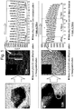
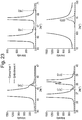
- FIG. 1 shows respective diffraction patterns and interplanar distances for a primary particle, which locates in a secondary particle, and a primary particle locating on the surface part of the secondary particle of the LiCoO 2 positive active material of Comparison 1.
- diffraction patterns of the primary particles locating in the internal part of the secondary particle of the LiCoO 2 positive active material and locating on the surface part of the secondary particle were all in hexagonal structure, and interplanar distances of the primary particles locating in the secondary particle and locating on the surface part of the secondary particle were all measured as 4.70 nm.
- NiCo(OH) 2 precursors were manufactured through a coprecipitation. Then, a lithium secondary battery positive active material was manufactured by adding Li 2 CO 3 and LiOH as lithium compounds to the manufactured precursors, adding Al and Mg as M1 thereto, and processing the mixture in first thermal treatment.
- the manufactured lithium secondary battery positive active material was washed by injecting the distilled water in uniform temperature.
- the surface of the positive active material was washed and coated with Co as M2 by agitating the positive active material while injecting a cobalt sulfate solution of 0.03 mol into the positive active material washing liquid for one hour in a specific ratio, and then dried at 120 °C under a vacuum.
- the lithium secondary battery positive active material was manufactured by adding Ti as M3 to the coated positive active material and processing the Ti-added positive active material in second thermal treatment at 450 °C.
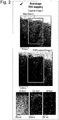
- the positive active material manufactured through Embodiment 1 of the inventive concept has Co concentration that is higher on the surface of the secondary particle and lower toward the inside from the surface of the secondary particle. Co concentration is ununiform in the secondary particle with a grade.
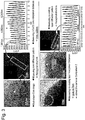
- FIG. 3 shows respective diffraction patterns and interplanar distances for primary particles locating in the internal part of the secondary particle manufactured through Embodiment 1 and locating on the surface part on which Co and Ti are coated.
- the thickness of a Co-coated layer is about 80 nm, and the diffraction pattern of the primary particle locating in the internal part of the secondary particle is in hexagonal structure.
- 10 adjacent interplanar distances were measured as 4.88 nm on average in a TEM photograph.
- the primary particle locating on the surface part having the Co-coated layer was measured as exhibiting a diffraction pattern of hexagonal structure with an interplanar distance of 4.73 nm.
- a positive active material of Embodiment 2 was manufactured in the same as Embodiment 1, except that concentration of a cobalt solution added to the positive active material washing liquid is 4 mol%.
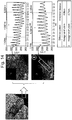
- FIG. 4 shows a result of measuring TEM and EDX photographs of the positive active material manufactures through Embodiment 2.
- the positive active material manufactured through Embodiment 2 of the inventive concept has Co concentration that is higher on the surface of the secondary particle and lower toward the inside of the secondary particle. That is, Co concentration of the positive active material is ununiform and distributed in a grade.
- FIG. 5 shows a result of measuring respective diffraction patterns and interplanar distances of primary particles locating in the internal part of the positive active material manufactured through Embodiment 1 and locating on the surface where Co and Ti are coated.
- a thickness of the Co-coated layer was about 90 nm
- a diffraction pattern of the primary particle locating in the internal part of the secondary particle was in a hexagonal structure
- an average of 10 adjacent interplanar distances of the primary particle locating in the internal part of the secondary particle was measured as 4.85 nm in a TEM photograph
- the primary particle locating on the surface part of the Co-coated layer had a diffraction pattern of hexagonal structure but an interplanar distance thereof was measured as 4.73 nm.
- a positive active material of Embodiment 3 was manufactured by executing a coating process with 5 mol% concentration of a cobalt solution added to the positive active material washing liquid.
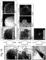
- FIG. 6 shows a result of measuring respective concentration variations of No, Co, and Al from the surface of the secondary particle of the positive active material, which is manufactured through Embodiment 3, toward the center of the particle.
- the positive active material manufactured through Embodiment 3 of the inventive concept has Co concentration that becomes higher toward the center from the surface in the Co-coated layer where Co is coated, but after the Co-coated layer, the Co concentration turns to be reduced as close as the center and a thickness of the Co-coated layer is 0.1 ⁇ m.
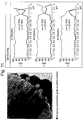
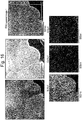
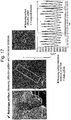
- FIG. 7 shows a result of measuring respective EDX photographs for Ni, Co, and Al from the surface of the secondary particle of the positive active material, which is manufactured through Embodiment 3, toward the center of the particle.
- the positive active material manufactured through Embodiment 3 of the inventive concept has Co concentration that becomes higher toward the center from the surface in the Co-coated layer where Co is coated, but after the Co-coated layer, the Co concentration turns to be reduced as close as the center and concentration of the Co-coated layer is higher along the boundaries of the primary particles.
- FIG. 8 shows a result of measuring respective diffraction patterns and interplanar distances of primary particles locating in the internal part of the positive active material manufactured through Embodiment 3 and locating on the surface on which Co and Ti are coated.
- a thickness of the Co-coated layer was about 100 nm
- a diffraction pattern of the primary particle locating in the internal part of the secondary particle was in a hexagonal structure
- an average of 10 adjacent interplanar distances of the primary particle locating in the internal part of the secondary particle was measured as 4.84 nm in a TEM photograph
- the primary particle locating on the Co-coated layer had a diffraction pattern of hexagonal structure but an interplanar distance thereof was measured as 4.67 nm.
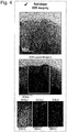
- a positive active material of Embodiment 4 was manufactured by executing a washing and coating process with 10 mol% concentration of a cobalt solution added to the positive active material washing liquid.
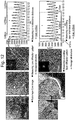
- FIG. 9 shows a result of measuring TEM and EDX photographs on the surface of the secondary particle of the positive active material manufactured through Embodiment 4.
- the positive active material manufactured through Embodiment 4 of the inventive concept has Co concentration that becomes higher on the surface of the secondary particle but turns to be lower as close as the center of the secondary particle.
- the Co concentration is ununiform in a grade.
- the EDX measurement shows a Co distribution of bar-shaped primary particle, from which it can be seen that Co concentration is measured as being higher at the periphery of the bar-shaped primary particle.
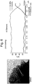
- FIG. 10 shows a result of measuring respective concentration variations of No, Co, and Al from the surface of a secondary particle of the positive active material, which is manufactured through Embodiment 4, toward the center of the particle.
- the positive active material manufactured through Embodiment 4 of the inventive concept has Co concentration that becomes higher toward the center from the surface in the Co-coated layer where Co is coated, but after the Co-coated layer, the Co concentration turns to be reduced as close as the center and a thickness of the Co-coated layer is 0.14 ⁇ m.
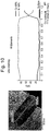
- FIG. 11 shows a result of measuring respective concentration variations of No, Co, and Al from three spots on the surface of a secondary particle of the positive active material, which is manufactured through Embodiment 4, toward the center of the secondary particle.
- FIG. 12 shows a result of measuring respective diffraction patterns and interplanar distances of primary particle locating in a secondary particle of the positive active material manufactured through Embodiment 4 and locating on the surface where Co and Ti are coated.
- a thickness of the Co-coated layer was about 140 nm
- a diffraction pattern of the primary particle locating in the internal part of the secondary particle was in a hexagonal structure
- interplanar distance of the primary particle locating in the internal part of the secondary particle was measured as 4.85 nm
- the primary particle locating on the surface, which was coated with Co and Ti had a diffraction pattern of hexagonal structure but its interplanar distance thereof was measured as 4.69 nm.
- FIG. 13 shows a result of measuring a diffraction pattern and interplanar distances from a boundary between the inside of a primary particle, which locates on the surface of a secondary particle of the positive active material manufactured through Embodiment 4, and a coated layer in the primary particle locating on the surface part of the secondary particle.
- the diffraction pattern was in a hexagonal structure and the interplanar distances were measured as 4.71 nm on average.
- FIG. 14 shows diffraction patterns and interplanar distances at boundaries of a primary particle locating on the surface of a secondary particle, which is coated with Co and Ti, of the positive active material manufactured through Embodiment 4.
- the diffraction patterns are in a hexagonal structure and the interplanar distances are measured as 4.69 nm and 4.71 nm as an intermediate value of interplanar distances between a core part and a coated layer part.
- a positive active material of Embodiment 5 was manufactured by manufacturing a lithium secondary battery positive active material, which had been processed through the first thermal treatment, in the composition of Li 1.02 Ni 0.816 Co 0.15 Al 0.034 O 2 without addition of Ti.
- a positive active material of Embodiment 6 was manufactured by manufacturing a lithium secondary battery positive active material, which had been processed through the first thermal treatment, in the composition of Li 1.02 Ni 0.903 Co 0.08 Al 0.014 Mg 0.003 O 2 .
- a positive active material of Embodiment 7 was manufactured by manufacturing a lithium secondary battery positive active material, which had been processed through the first thermal treatment, in the composition of Li 1.00 Ni 0.965 Co 0.02 Al 0.014 Mg 0.001 O 2 .
- a positive active material of Embodiment 8 was manufactured by executing a coating process with 4 mol% concentration of a cobalt solution which was added to the positive active material washing liquid.
- a positive active material of Embodiment 9 was manufactured by executing a coating process with 5 mol% concentration of a cobalt solution which was added to the positive active material washing liquid.
- a positive active material of Embodiment 10 was manufactured by manufacturing a lithium secondary battery positive active material, which had been processed through the first thermal treatment, in the composition of Li 1.00 Ni 0.985 Al 0.014 Mg 0.001 O 2 .
- a positive active material of Comparison 2 was manufactured by injecting active material particles into a 0.1 mol cobalt solution, coating the active material with cobalt while agitating the mixture, and drying the coated material.
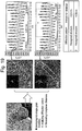
- FIG. 15 shows a result of measuring TEM and EDX photographs from the surface of a secondary particle of the positive active material manufactured through Comparison 2.
- the positive active material resulted in an uneven surface, without being doped into the inside, because there was no subsequent thermal treatment even though the Co distribution was concentrated on the surface due to the agitation with the active material particles which were injected into the cobalt solution.
- a positive active material of Comparison 4 was manufactured by adding Ti with concentration of 0.001 mol and then executing a second thermal treatment.
- a positive active material of Comparison 6 was prepared by manufacturing a lithium secondary battery positive active material, which had been processed through a first thermal treatment, in the composition of Li 1.00 Ni 0.815 Co 0.15 Al 0.014 O 2 .
- a positive active material of Comparison 7 was prepared by manufacturing a lithium secondary battery positive active material, which had been processed through a first thermal treatment, in the composition of Li 1.02 Ni 0.903 Co 0.08 Al 0.014 Mg 0.003 O 2 .
- a positive active material of Comparison 8 was prepared by manufacturing a lithium secondary battery positive active material, which had been processed through a first thermal treatment, in the composition of Li 1.00 Ni 0.965 Co 0.02 Al 0.014 Mg 0.001 O 2 .
- a positive active material of Comparison 9 was prepared by manufacturing a lithium secondary battery positive active material, which had been processed through a first thermal treatment, in the composition of Li 1.00 Ni 0.985 Al 0.014 Mg 0.001 O 2 .
- FIG. 16 shows a result of measuring TEM and EDX photographs from the surface of a secondary particle of the positive active material manufactured through Comparison 4.
- the positive active material manufactured through Comparison 4 has Co concentration uniformly distributed in the particle, because a Co coating process is not preformed after manufacturing an active material, and a Co concentration grade toward the inside of the particle is not found on the surface.
- FIG. 17 shows a result of measuring respective a diffraction pattern and interplanar distances from the surface of a secondary particle of the positive active material manufactured through Embodiment 4.
- a diffraction pattern of the surface was in a hexagonal structure and the interplanar distances were measured as 4.85 nm on average.
- FIG. 18 shows a result of measuring a diffraction pattern and interplanar distances of a primary particle locating in a secondary particle of the positive active material manufactured through Comparison 4.
- the primary particle locating in the secondary particle of the positive active material has a diffraction pattern of hexagonal structure and interplanar distances of 4.83 nm on average. It can be also seen that, even with a second thermal treatment in the case without a Co coating process, the interplanar distance of the primary particle locating in the secondary particle of the positive active material is almost similar to that of a primary particle locating on the surface of the secondary particle.
- FIG. 19 shows a result of measuring diffraction patterns and interplanar distances from a boundary of a primary particle locating on the surface of a secondary particle of the positive active material manufactured through Embodiment 4.
- the primary particle locating on the surface of the secondary particle of the positive active material was measured as having a diffraction pattern of hexagonal structure and interplanar distances of 4.81 nm on average.
- FIGS. 18 and 19 it can be seen from FIGS. 18 and 19 that, in the case without a Co coating process, diffraction patterns and interplanar distances are similar between the inside and the boundary of the primary particle.
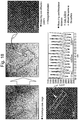
- FIG. 20 shows a result of measuring respective concentration of Ni, Co, and Al toward the core from the surface of a secondary particle of the positive active material manufactured through Comparison 4.
- the positive active material manufactured through Comparison 4 has uniform concentration of Ni, Co, and Al in the particle.
- FIG. 21 shows a result of measuring respective concentration of Ni, Co, and Al in a direction horizontal to the surface direction of a primary particle locating on the surface of a secondary particle of the positive active material manufactured through Comparison 4.
- the positive active material manufactured through Comparison 4 has uniform concentration of Ni, Co, and Al in the particle, without a Co concentration grade due to absence of a CO coating process, and interplanar distances thereof are also similar between the surface and the inside.
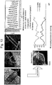
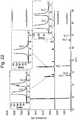
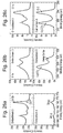
- FIG. 24 A result of measuring XRD for a positive active material of Comparison 2 is shown in FIG. 24 .
- FIG. 25 shows a result of measuring XRD for positive active materials manufactured through Comparison 4, which does not execute a Co coating process, and through Embodiment 4 executing a thermal treatment after a Co coating process.
- FIG. 26 shows results of measuring XPS for positive active materials manufactured through Comparison 4, which does not execute a Co coating process, and through Embodiment 3 executing a coating process with a cobalt solution which has concentration of 5 mol%.
- Slurry was manufactured by mixing the positive active materials, which were manufactured through Embodiments 1 to 10 and Comparisons 4, and 6 to 9, super-P as a conducting agent, and polyvinylidenefluoride (PVdF) as a binding agent in weight ratio of 92:5:3. Then an anode for a lithium secondary battery was manufactured by uniformly coating the slurry on an aluminum foil which has a thickness of 15 ⁇ m, and then by drying the slurry-coated aluminum foil at 135 °C under vacuum.
- PVdF polyvinylidenefluoride
- a coin battery was manufactured by using the anode and a lithium foil as the other electrode, using a porous polyethylene film (Celgard 2300 made by Celgard LLC; thickness of 25 ⁇ m) as a separator, and using a liquid electrolyte in which LiPF6 with concentration of 1.15 M was dissolved in a solvent in which ethylene carbonate and ethylmethyl carbonate are mixed in a volume ratio of 3:7.
- a porous polyethylene film (Celgard 2300 made by Celgard LLC; thickness of 25 ⁇ m) as a separator
- LiPF6 with concentration of 1.15 M was dissolved in a solvent in which ethylene carbonate and ethylmethyl carbonate are mixed in a volume ratio of 3:7.
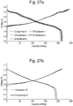
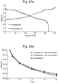
- FIG. 27A Embodiments 1 to 4, Comparison 4
- FIG. 27B Embodiment 5, Comparison 6
- FIG. 27C Embodiment 6, Comparison 7
- FIG. 27D Embodiments 7 to 9, Comparison 8
- FIG. 27E Embodiment 10, Comparison 9
- the coating process executed according to the embodiments of the inventive concept contributed to the characteristics of capacity and efficiency that was measured as being more improved than that of a comparison examples.
- Embodiment 1 242.2 215.9 89.1 Embodiment 2 239.9 214.4 89.4 Embodiment 3 239.0 215.0 90.0 Embodiment 4 231.7 215.2 92.9 Embodiment 5 213.9 194.1 90.8 Embodiment 6 232.5 213.7 91.9 Embodiment 7 248.9 222.3 89.3 Embodiment 8 247.2 222.5 90.0 Embodiment 9 245.1 220.9 90.1 Embodiment 10 251.8 221.6 88.0 Comparison 4 244.5 209.7 85.8 Comparison 6 217.1 190.2 87.6 Comparison 7 239.3 211.3 88.3 Comparison 8 255.1 219.0 85.9 Comparison 9 258.2 221.6 85.8
- FIG. 28A Embodiments 1 to 4, Comparison 4
- FIG. 28B Embodiment 5, Comparison 6
- FIG. 28C Embodiment 6, Comparison 7
- FIG. 28D Embodiments 7 to 9, Comparison 8
- FIG. 28E Embodiment 10, Comparison 9
- the coating process executed by the embodiments of the inventive concept contributed to making the characteristics of capacity and efficiency measured as being more improved than the comparison examples.
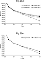
- FIG. 29A Embodiments 1 to 4, Comparison 4
- FIG. 29C Embodiment 5, Comparison 6
- FIG. 29C Embodiment 6, Comparison 7
- FIG. 29D Embodiments 7 to 9, Comparison 8
- FIG. 29E Embodiment 10, Comparison 9
- the coating process executed according to the embodiments of the inventive concept contributed to making the characteristics of lifetime measured as being more improved than the comparison examples.
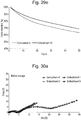
- FIG. 30A Embodiments 1 to 3, Comparison 4
- FIG. 30B Embodiment 5, Comparison 6
- FIG. 30C Embodiment 6, Comparison 7
- FIG. 30D Embodiments 7 to 9, Comparison 8
- FIG. 30E Embodiment 10, Comparison 9
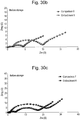
- FIG. 31A Embodiments 1 to 3, Comparison 4
- FIG. 31B Embodiment 5, Comparison 6
- FIG. 31C Embodiment 6, Comparison 7
- FIG. 31D Embodiments 7 to 9, Comparison 8
- FIG. 31E Embodiment 10, Comparison 9
- the coating process executed by the embodiments of the inventive concept contributed to greatly improving the high temperature storage characteristics because impedances after high temperature storage increased less than those of the comparison examples.
- a secondary battery in the characteristics of capacity, resistance, and lifetime with different interplanar distances of crystalline structures between a primary particle locating on the surface part of a secondary particle and a primary particle locating in the internal part of the secondary particle by coating different elements and washing in the processes of forming precursors and/or an active material.
- a secondary battery in the characteristics of capacity, resistance, and lifetime with different interplanar distances of crystalline structures between a primary particle locating on the surface part of a secondary particle and a primary particle locating in the internal part of the secondary particle by coating different elements and washing in the processes of forming precursors and/or an active material.
Landscapes
- Chemical & Material Sciences (AREA)
- Chemical Kinetics & Catalysis (AREA)
- Electrochemistry (AREA)
- General Chemical & Material Sciences (AREA)
- Inorganic Chemistry (AREA)
- Engineering & Computer Science (AREA)
- Materials Engineering (AREA)
- Composite Materials (AREA)
- Organic Chemistry (AREA)
- Manufacturing & Machinery (AREA)
- Battery Electrode And Active Subsutance (AREA)
- Inorganic Compounds Of Heavy Metals (AREA)
Description
- Embodiments of the inventive concept described herein relate to a lithium complex oxide for a secondary battery and a method of preparing the same, and more particularly, relate to a lithium complex oxide for a secondary battery, and a method of preparing the same, improving the characteristics of capacity, resistance, and battery lifetime with different interplanar distances of crystalline structure between a primary particle locating on the surface of a secondary particle and a primary particle locating in the secondary particle by coating different elements on the surface, in consideration of inclination to functional degradation but reduction of residual lithium after a washing for removing the residual lithium in a preparation process, for a positive active material where lithium ion pathways in a-axis and c-axis of a crystalline structure.
- With an increase of technology and demand for mobile devices, secondary batteries as energy sources are increasing in demand. Among secondary batteries, lithium (Li) secondary batteries are being now commercialized and widely used on the merits of high energy density and operating potential, long cycle lifetime, and low discharge rate.
- A positive active material for a lithium secondary battery usually employs a lithium-contained cobalt oxide (LiCoO2). It is also considered therefor even to use a lithium-contained manganese oxide such as layered crystalline structure of LiMnO2 or spinel crystalline structure of LiMn2O4, or a lithium-contained nickel oxide such as LiNiO2.
- Among those positive active materials, LiCoO2 is most frequently used because of good characteristics of battery lifetime and charge/discharge efficiency, but there is a limit to competitiveness of cost in mass use as power sources for middle/large-scale batteries of electric vehicles because cobalt (Co) is rare and expensive as a resource, and small in capacity. Although the lithium manganese oxide such as LiMnO2 or LiMn2O4, as the positive active material, is low in price, eco-friendly, and highly stable in heat, it is deteriorative in high temperature and cycle characteristics.
- A method of preparing a lithium complex oxide generally includes the steps of manufacturing transition metal precursors, mixing a lithium compound and the transition metal precursors, and then baking the mixture. During this, LiOH and/or Li2CO3 are/is used for the lithium compound. It is generally preferred to use Li2CO3 in the case that Ni content of the positive active material is equal to or lower than 65% and preferred to use LiOH in the case that Ni content of the positive active material is equal to or higher than 65%.
- However, a nickel (Ni) rich system containing nickel equal to or higher than 65%, reactive at a low temperature, has a problem of having much residual lithium which remains in a form of LiOH and Li2CO3 on the surface of a positive active material. The residual lithium, that is, unreacted LiOH and Li2CO3 generate gas and a swelling effect by reacting with an electrolyte in the battery, and then cause high temperature stability to be seriously worse. Additionally, the unreacted LiOH also causes gelation because its viscosity is high when mixing slurry before manufacturing electrode plates.
- To remove such unreacted Li, a washing process is executed generally after preparing a positive active material, thereby much reducing residual lithium. However, during the washing process, the surface of the positive active material was damaged and degraded in characteristics of capacity and efficiency. Additionally, there was another problem to increase resistance in high temperature storage. Therefore, it is necessary to improve the characteristics of capacity, efficiency, and battery lifetime as well as to reduce residual lithium.
US 2016/181611 disclose a Li-complex oxide secondary particle formed by multiple primary particles, where Co concentration decreases continuously from a coating film to the center of the primary particle. -
US 2012/009474 A1 discloses a Li-complex oxide secondary particle formed by plurality of primary particles, where "the amount of cobalt in the primary particle at the surface of the secondary particle is greater than the amount of cobalt in the primary particle around the center of the secondary particle". The document also discloses a method for preparing the active material, involving reacting precursors, thermal treatment; washing; coating with Co; and second heat treatment. -
EP 2 634 148 A1 - The invention is defined by the claims.
- Embodiments of the inventive concept provide a lithium complex oxide of a new structure improving the characteristics of capacity, resistance, and battery lifetime as well as reducing residual lithium.
- According to an aspect of the inventive concept, the invention provides a lithium complex oxide secondary particle formed by coagulation of a plurality of primary particles, wherein Co concentration at a boundary of the primary particle is higher than Co concentration in the primary particle, that is in the internal part of the primary particle, wherein: the Co concentration of a primary particle at a part of the primary particle which is in contact with the surface of the secondary particle is higher than at a part of the primary particle that is not in contact with the surface of the secondary particle, wherein the primary particle is located at a surface part of the secondary particle; a primary particle located at a surface of the secondary particle has a Co ion concentration gradient toward a center of the primary particle from the surface of the primary particle; a primary particle located at a surface part of the secondary particle has a Co concentration gradient that is reduced by 0.05 to 0.07 mol% per nm toward a center of the primary particle; the lithium complex oxide secondary particle comprises a hexagonal crystal structure; and the secondary particle has a bound energy (P1) of spin-orbit 2p3/2 peak and a bound energy (P2) of 2p1/2 peak in a
Co 2p core-level spectrometry obtained through XPS measurement, wherein the P1 and the P2 are ranged respectively in 779eV≤P1≤780eV and 794eV≤P2≤795eV. - In the lithium complex oxide secondary particle according to the inventive concept, a primary particle located at the surface part of the secondary particle may be configured to satisfy that dc/dh is 2 to 10, where the dc is a length toward a center and the dh is a length vertical to the center. That is, primary particles forming the surface of secondary particle according to the inventive concept may be shaped in an oval or stick that has an aspect ratio of 2 to 10.
- In the lithium complex oxide secondary particle according to the inventive concept, the secondary particle may have at least one peak at positions (104), (110), (113), (101), (102), and (003) during XRD analysis. The peaks maybe specific peaks generated from LiCoO2, appearing by a coating with the different metals after a washing process.
- In the lithium complex oxide secondary particle according to the inventive concept, the secondary particle may have a ratio of peak intensity (I531) around 531 eV and peak intensity (I528) around 528.5 eV during an
O 1s core-level spectrometry that is obtained through XPS measurement, wherein the ratio may be I531/I528≤2. - In the lithium complex oxide secondary particle according to the inventive concept, the secondary particle has a ratio between peak intensity (I289) around 289 eV and peak intensity (I284) around 284.5 eV during a
C 1s core-level spectrometry that is obtained through XPS measurement, wherein the ratio is I289/I284≤0.9. - In the lithium complex oxide secondary particle according to the inventive concept, the secondary particle may be given by the following
Formula 1,
[Formula 1] LixNi1-(a1+b1+c1)Coa1M1b1M2c1M3dOy,
wherein, in the Formula 1, M1 may be Mn or Al, and M2 and M3 are metals selected from a group of Al, Ba, B, Co, Ce, Cr, F, Li, Mg, Mn, Mo, P, Sr, Ti, and Zr, and wherein 0.95≤x≤1.05, 1.50≤y≤2.1, 0.02≤a1≤0.25, 0.01≤b1≤0.20, 0≤c1≤0.20, and 0≤d≤0.20. - According to another aspect of the inventive concept, a method of preparing the lithium complex oxide secondary particle may include manufacturing precursors of lithium secondary battery positive active materials given by the following Formula 2,
[Formula 2] Ni1-(x2+y2+z2)Cox2M1y2M2z2(OH)2,
wherein, in Formula 2, M1 is Mn or Al, and M2 is a metal selected from a group of Al, Ba, B, Co, Ce, Cr, F, Li, Mg, Mn, Mo, P, Sr, Ti, and Zr, and wherein 0≤x2≤0.25, 0≤y2≤0.20, and 0≤z2≤0.20, reacting precursors of lithium secondary battery positive active materials with a lithium compound and manufacturing a positive active material by first thermal treating the reactant, washing the positive active material with distilled water or an alkaline solution, reactively coating the washed positive active material with a solution containing M2 being Co drying particles of the positive active material, and mixing the dried positive active material with M3 that is a metal selected from the group of Al, Ba, B, Ce, Cr, F, Li, Mg, Mn, Mo, P, Sr, Ti, and Zr and doping the metal M3 into the particles by second thermal treating the mixture. - In the method of preparing a lithium complex oxide secondary particle according to the inventive concept, the reactively coating may include reactively coating the washed positive active material with the solution containing Co ion.
- In the method of preparing a lithium complex oxide secondary particle according to the inventive concept, in the reactively coating, a thickness of a graded Co concentration part formed on a surface of the secondary particle may vary according to the solution containing Co.
- In the method of preparing a lithium complex oxide secondary particle according to the inventive concept, in the reactively coating, the solution containing Co has concentration of 1 to 10 mol%.
- According to still another aspect of the inventive concept, a lithium secondary battery includes a lithium complex oxide secondary particle prepared according to embodiments of the inventive concept.
- The lithium secondary battery according to the inventive concept may have a residual lithium equal to or smaller than 6,000 ppm.
- The above and other objects and features will become apparent from the following description with reference to the following figures, wherein like reference numerals refer to like parts throughout the various figures unless otherwise specified, and wherein:
-
FIG. 1 shows a result of measuring diffraction patterns and interplanar distances of an LiCoO2 positive active material ofComparison 1 according to the inventive concept; -
FIG. 2 shows a result of measuring TEM and EDX photographs of a positive active material prepared according to an embodiment of the inventive concept; -
FIG. 3 shows a result of measuring diffraction patterns and interplanar distances of a positive active material prepared according to an embodiment of the inventive concept; -
FIG. 4 shows a result of measuring TEM and EDX photographs of a positive active material prepared according to an embodiment of the inventive concept; -
FIG. 5 shows a result of measuring diffraction patterns and interplanar distances of a positive active material prepared according to an embodiment of the inventive concept; -
FIG. 6 shows a result of measuring respective variations of concentration for Ni, Co, and Al toward the center from the surface of a positive active material prepared according to an embodiment of the inventive concept; -
FIG. 7 shows a result of measuring an EDX photograph of a positive active material prepared according to an embodiment of the inventive concept; -
FIG. 8 shows a result of measuring diffraction patterns and interplanar distances of a positive active material prepared according to an embodiment of the inventive concept; -
FIG. 9 shows a result of measuring TEM and EDX photographs of a positive active material prepared according to an embodiment of the inventive concept; -
FIG. 10 shows a result of measuring respective variations of concentration for Ni, Co, and Al toward the center from the surface of a positive active material prepared according to an embodiment of the inventive concept; -
FIG. 11 shows a result of measuring respective variations of concentration for Ni, Co, and Al toward the center from a third spot of a positive active material prepared according to an embodiment of the inventive concept; -
FIGS. 12 to 14 show results of measuring diffraction patterns and interplanar distances of positive active materials manufactured by comparison examples and embodiments of the inventive concept; -
FIGS. 15 and16 show results of measuring EDX photographs of positive active materials manufactured by comparison examples of the inventive concept; -
FIGS. 17 to 19 show results of measuring diffraction patterns and interplanar distances of positive active materials manufactured by comparison examples and embodiments of the inventive concept; -
FIGS. 20 and21 show results of measuring respective variations of concentration for Ni, Co, and Al toward the center from the surface of a positive active material prepared according to an embodiment of the inventive concept; -
FIGS. 22 to 25 show results of measuring XRD of positive active materials manufactured by comparison examples and embodiments of the inventive concept; -
FIG. 26 shows a result of measuring XPS of positive active materials manufactured by a comparison example and an embodiment of the inventive concept; and -
FIGS. 27A to 31E show results of measuring the characteristics of batteries including positive active materials manufactured by comparison examples and embodiments of the inventive concept. - Hereafter, embodiments of the inventive concept will be described in detail with reference to the accompanying figures. The inventive concept may not be however restrictive to the embodiments proposed below.
- A LiCoO2 positive active material, which is commercially sold, was used for
Comparison 1. -
FIG. 1 shows respective diffraction patterns and interplanar distances for a primary particle, which locates in a secondary particle, and a primary particle locating on the surface part of the secondary particle of the LiCoO2 positive active material ofComparison 1. - After mounting the LiCoO2 positive active material on a carbon grid, coating the LiCoO2 positive active material with carbon and PT, and then magnifying the coated LiCoO2 positive active material in 20 million or 25 million times through a TEM pre-treatment that slices the coated LiCoO2 positive active material, ten interplanar distances were measured left and light around an interplanar distance to be known.
- As shown in
FIG. 1 , diffraction patterns of the primary particles locating in the internal part of the secondary particle of the LiCoO2 positive active material and locating on the surface part of the secondary particle were all in hexagonal structure, and interplanar distances of the primary particles locating in the secondary particle and locating on the surface part of the secondary particle were all measured as 4.70 nm. - First, NiCo(OH)2 precursors were manufactured through a coprecipitation. Then, a lithium secondary battery positive active material was manufactured by adding Li2CO3 and LiOH as lithium compounds to the manufactured precursors, adding Al and Mg as M1 thereto, and processing the mixture in first thermal treatment.
- After preparing distilled water, the manufactured lithium secondary battery positive active material was washed by injecting the distilled water in uniform temperature.
- Afterward, the surface of the positive active material was washed and coated with Co as M2 by agitating the positive active material while injecting a cobalt sulfate solution of 0.03 mol into the positive active material washing liquid for one hour in a specific ratio, and then dried at 120 °C under a vacuum.
- Then, the lithium secondary battery positive active material was manufactured by adding Ti as M3 to the coated positive active material and processing the Ti-added positive active material in second thermal treatment at 450 °C.
- TEM and EDX photographs were taken from the positive active material manufactured through
Embodiment 1 and shown inFIG. 2 . - As shown in
FIG. 2 , the positive active material manufactured throughEmbodiment 1 of the inventive concept has Co concentration that is higher on the surface of the secondary particle and lower toward the inside from the surface of the secondary particle. Co concentration is ununiform in the secondary particle with a grade. -
FIG. 3 shows respective diffraction patterns and interplanar distances for primary particles locating in the internal part of the secondary particle manufactured throughEmbodiment 1 and locating on the surface part on which Co and Ti are coated. - As shown in
FIG. 3 , the thickness of a Co-coated layer is about 80 nm, and the diffraction pattern of the primary particle locating in the internal part of the secondary particle is in hexagonal structure. For the primary particle locating in the secondary particle, 10 adjacent interplanar distances were measured as 4.88 nm on average in a TEM photograph. Comparatively, the primary particle locating on the surface part having the Co-coated layer was measured as exhibiting a diffraction pattern of hexagonal structure with an interplanar distance of 4.73 nm. - From this result, it can be seen that the interplanar distance of the primary particle locating on the surface part was relatively reduced in comparison with the primary particle locating in the internal part of the secondary particle which was not coated with cobalt, and the interplanar distance of the primary particle locating on the surface part was changed similar to an interplanar distance of LiCoO2 of a comparison example.
- A positive active material of
Embodiment 2 was manufactured in the same asEmbodiment 1, except that concentration of a cobalt solution added to the positive active material washing liquid is 4 mol%. -
FIG. 4 shows a result of measuring TEM and EDX photographs of the positive active material manufactures throughEmbodiment 2. - As shown in
FIG. 4 , it can be seen that the positive active material manufactured throughEmbodiment 2 of the inventive concept has Co concentration that is higher on the surface of the secondary particle and lower toward the inside of the secondary particle. That is, Co concentration of the positive active material is ununiform and distributed in a grade. -
FIG. 5 shows a result of measuring respective diffraction patterns and interplanar distances of primary particles locating in the internal part of the positive active material manufactured throughEmbodiment 1 and locating on the surface where Co and Ti are coated. - As shown in
FIG. 5 , it was measured that a thickness of the Co-coated layer was about 90 nm, a diffraction pattern of the primary particle locating in the internal part of the secondary particle was in a hexagonal structure, and an average of 10 adjacent interplanar distances of the primary particle locating in the internal part of the secondary particle was measured as 4.85 nm in a TEM photograph, while the primary particle locating on the surface part of the Co-coated layer had a diffraction pattern of hexagonal structure but an interplanar distance thereof was measured as 4.73 nm. - It can be seen that, comparative to the primary particle locating in the Co-uncoated secondary particle, the interplanar distance of the primary particle locating on the surface part was reduced and changed similar to the interplanar distance of LiCoO2 of a comparison example.
- In the same manner with
Embodiment 1, a positive active material ofEmbodiment 3 was manufactured by executing a coating process with 5 mol% concentration of a cobalt solution added to the positive active material washing liquid. -
FIG. 6 shows a result of measuring respective concentration variations of No, Co, and Al from the surface of the secondary particle of the positive active material, which is manufactured throughEmbodiment 3, toward the center of the particle. - From
FIG. 6 , it can be seen that the positive active material manufactured throughEmbodiment 3 of the inventive concept has Co concentration that becomes higher toward the center from the surface in the Co-coated layer where Co is coated, but after the Co-coated layer, the Co concentration turns to be reduced as close as the center and a thickness of the Co-coated layer is 0.1 µm. -
FIG. 7 shows a result of measuring respective EDX photographs for Ni, Co, and Al from the surface of the secondary particle of the positive active material, which is manufactured throughEmbodiment 3, toward the center of the particle. - From
FIG. 7 , it can be seen that the positive active material manufactured throughEmbodiment 3 of the inventive concept has Co concentration that becomes higher toward the center from the surface in the Co-coated layer where Co is coated, but after the Co-coated layer, the Co concentration turns to be reduced as close as the center and concentration of the Co-coated layer is higher along the boundaries of the primary particles. -
FIG. 8 shows a result of measuring respective diffraction patterns and interplanar distances of primary particles locating in the internal part of the positive active material manufactured throughEmbodiment 3 and locating on the surface on which Co and Ti are coated. - As shown in
FIG. 8 , it was measured that a thickness of the Co-coated layer was about 100 nm, a diffraction pattern of the primary particle locating in the internal part of the secondary particle was in a hexagonal structure, and an average of 10 adjacent interplanar distances of the primary particle locating in the internal part of the secondary particle was measured as 4.84 nm in a TEM photograph, while the primary particle locating on the Co-coated layer had a diffraction pattern of hexagonal structure but an interplanar distance thereof was measured as 4.67 nm. - It can be seen that, comparative to the primary particle locating in the Co-uncoated secondary particle, the interplanar distance of the primary particle locating on the Co-coated surface was reduced and changed similar to interplanar distances of LiCoO2 of a comparison example.
- In the same manner with
Embodiment 1, a positive active material ofEmbodiment 4 was manufactured by executing a washing and coating process with 10 mol% concentration of a cobalt solution added to the positive active material washing liquid. -
FIG. 9 shows a result of measuring TEM and EDX photographs on the surface of the secondary particle of the positive active material manufactured throughEmbodiment 4. - As shown in
FIG. 9 , it can be seen that the positive active material manufactured throughEmbodiment 4 of the inventive concept has Co concentration that becomes higher on the surface of the secondary particle but turns to be lower as close as the center of the secondary particle. Thus, the Co concentration is ununiform in a grade. - Additionally, the EDX measurement shows a Co distribution of bar-shaped primary particle, from which it can be seen that Co concentration is measured as being higher at the periphery of the bar-shaped primary particle.
-
FIG. 10 shows a result of measuring respective concentration variations of No, Co, and Al from the surface of a secondary particle of the positive active material, which is manufactured throughEmbodiment 4, toward the center of the particle. - From
FIG. 10 , it can be seen that the positive active material manufactured throughEmbodiment 4 of the inventive concept has Co concentration that becomes higher toward the center from the surface in the Co-coated layer where Co is coated, but after the Co-coated layer, the Co concentration turns to be reduced as close as the center and a thickness of the Co-coated layer is 0.14 µm. -
FIG. 11 shows a result of measuring respective concentration variations of No, Co, and Al from three spots on the surface of a secondary particle of the positive active material, which is manufactured throughEmbodiment 4, toward the center of the secondary particle. - From
FIG. 11 , it can be seen that three independent spots on the surface of the secondary particle of the positive active material manufactured throughEmbodiment 4 have thicknesses of 0.14 µm that forms a uniform grade therein. -
FIG. 12 shows a result of measuring respective diffraction patterns and interplanar distances of primary particle locating in a secondary particle of the positive active material manufactured throughEmbodiment 4 and locating on the surface where Co and Ti are coated. - As shown in
FIG. 12 , it was measured that a thickness of the Co-coated layer was about 140 nm, a diffraction pattern of the primary particle locating in the internal part of the secondary particle was in a hexagonal structure, and interplanar distance of the primary particle locating in the internal part of the secondary particle was measured as 4.85 nm, while the primary particle locating on the surface, which was coated with Co and Ti, had a diffraction pattern of hexagonal structure but its interplanar distance thereof was measured as 4.69 nm. - It can be seen that, comparative to the primary particle locating in the Co-uncoated secondary particle, the interplanar distance of the primary particle locating on the Co-coated surface was reduced and changed similar to the interplanar distance of LiCoO2 of a comparison example.
-
FIG. 13 shows a result of measuring a diffraction pattern and interplanar distances from a boundary between the inside of a primary particle, which locates on the surface of a secondary particle of the positive active material manufactured throughEmbodiment 4, and a coated layer in the primary particle locating on the surface part of the secondary particle. - As shown in
FIG. 13 , from the boundary between the inside of the primary particle, which locates on the surface of the secondary particle of the positive active material manufactured throughEmbodiment 4, and the coated layer, which is coated with Co and Ti, in the primary particle locating on the surface part of the secondary particle, the diffraction pattern was in a hexagonal structure and the interplanar distances were measured as 4.71 nm on average. - It can be seen that, comparative to the primary particle locating in the internal part of the secondary particle has an interplanar distance of 4.85 nm and the primary particle locating on the surface part of the secondary particle, which is coated with Co and Ti, has an interplanar distance of 4.69 nm, the interplanar distance of the coated layer boundary in the primary particle locating on the surface part of the secondary particle coated with Co and Ti, that is, 4.71 nm, was measured as an intermediate value between the interplanar distance of the primary particle locating in the internal part of the secondary particle and the interplanar distance of the primary particle locating on the surface part of the secondary particle which is coated with Co and Ti.
- Additionally, it can be seen that the interplanar distance of the primary particle at the coated layer boundary was changed similar to the interplanar distance of LiCoO2 of a comparison example.
-
FIG. 14 shows diffraction patterns and interplanar distances at boundaries of a primary particle locating on the surface of a secondary particle, which is coated with Co and Ti, of the positive active material manufactured throughEmbodiment 4. - As shown in
FIG. 14 , from the boundaries of the primary particle locating on the surface part of the secondary particle of the positive active material, the diffraction patterns are in a hexagonal structure and the interplanar distances are measured as 4.69 nm and 4.71 nm as an intermediate value of interplanar distances between a core part and a coated layer part. - Additionally, it can be seen that the interplanar distance of the primary particle at the coated layer boundary was changed similar to the interplanar distance of LiCoO2 of a comparison example.
- In the same manner with
Embodiment 1, a positive active material ofEmbodiment 5 was manufactured by manufacturing a lithium secondary battery positive active material, which had been processed through the first thermal treatment, in the composition of Li1.02Ni0.816Co0.15Al0.034O2 without addition of Ti. - In the same manner with
Embodiment 1, a positive active material ofEmbodiment 6 was manufactured by manufacturing a lithium secondary battery positive active material, which had been processed through the first thermal treatment, in the composition of Li1.02Ni0.903Co0.08Al0.014Mg0.003O2. - In the same manner with
Embodiment 1, a positive active material ofEmbodiment 7 was manufactured by manufacturing a lithium secondary battery positive active material, which had been processed through the first thermal treatment, in the composition of Li1.00Ni0.965Co0.02Al0.014Mg0.001O2. - In the same manner with
Embodiment 7, a positive active material ofEmbodiment 8 was manufactured by executing a coating process with 4 mol% concentration of a cobalt solution which was added to the positive active material washing liquid. - In the same manner with
Embodiment 7, a positive active material ofEmbodiment 9 was manufactured by executing a coating process with 5 mol% concentration of a cobalt solution which was added to the positive active material washing liquid. - In the same manner with
Embodiment 7, a positive active material ofEmbodiment 10 was manufactured by manufacturing a lithium secondary battery positive active material, which had been processed through the first thermal treatment, in the composition of Li1.00Ni0.985Al0.014Mg0.001O2. - The final formulas of compositions used in
Embodiments 1 to 10 are summarized in Table 1 as follows.[Table 1] Final Composition Formula LiX1Ni1-(x1+y1+z1)Cox1M1y1M2z1M3r1Oa Embodiment 1 Li1.01Ni0.903Co0.08Al0.015Mg0.001Ti0.001O2 Embodiment 2 Li1.01Ni0.893Co0.09Al0.015Mg0.001Ti0.001O2 Embodiment 3 Li1.02Ni0.883Co0.10Al0.015Mg0.001Ti0.001O2 Embodiment 4 Li1.02Ni0.833Co0.10Al0.015Mg0.001Ti0.001O2 Embodiment 5 Li1.02Ni0.786Co0.18Al0.034O2 Embodiment 6 Li1.02Ni0.873Co0.11Al0.015Mg0.001Ti0.005O2 Embodiment 7 Li1.00Ni0.933Co0.05Al0.015Mg0.001Ti0.001O2 Embodiment 8 Li1.00Ni0.923Co0.06Al0.015Mg0.001Ti0.001O2 Embodiment 9 Li1.00Ni0.913Co0.07Al0.015Mg0.001Ti0.001O2 Embodiment 10 Li1.00Ni0.953Co0.03Al0.015Mg0.001Ti0.001O2 - In the same manner with
Embodiment 4, a positive active material ofComparison 2 was manufactured by injecting active material particles into a 0.1 mol cobalt solution, coating the active material with cobalt while agitating the mixture, and drying the coated material. - In the same manner with
Embodiment 4, a positive active material ofComparison 3 was manufactured, without including Co during a washing process, by excluding a Ti adding process and a second thermal treatment. -
FIG. 15 shows a result of measuring TEM and EDX photographs from the surface of a secondary particle of the positive active material manufactured throughComparison 2. - As shown in
FIG. 15 , it can be seen that the positive active material resulted in an uneven surface, without being doped into the inside, because there was no subsequent thermal treatment even though the Co distribution was concentrated on the surface due to the agitation with the active material particles which were injected into the cobalt solution. - In the same manner with
Comparison 3, a positive active material ofComparison 4 was manufactured by adding Ti with concentration of 0.001 mol and then executing a second thermal treatment. - In the same manner with
Comparison 3, a positive active material ofComparison 5 was prepared, without a washing process, after manufacturing a lithium secondary battery positive active material which had been processed through a first thermal treatment. - In the same manner with
Comparison 3, a positive active material ofComparison 6 was prepared by manufacturing a lithium secondary battery positive active material, which had been processed through a first thermal treatment, in the composition of Li1.00Ni0.815Co0.15Al0.014O2. - In the same manner with
Comparison 4, a positive active material ofComparison 7 was prepared by manufacturing a lithium secondary battery positive active material, which had been processed through a first thermal treatment, in the composition of Li1.02Ni0.903Co0.08Al0.014 Mg0.003O2. - In the same manner with
Comparison 4, a positive active material ofComparison 8 was prepared by manufacturing a lithium secondary battery positive active material, which had been processed through a first thermal treatment, in the composition of Li1.00Ni0.965Co0.02Al0.014 Mg0.001O2. - In the same manner with
Comparison 4, a positive active material ofComparison 9 was prepared by manufacturing a lithium secondary battery positive active material, which had been processed through a first thermal treatment, in the composition of Li1.00Ni0.985Al0.014 Mg0.001O2. - The final formulas of compositions used in
Comparisons 1 to 9 are summarized in Table 2 as follows. - The final formulas of compositions used in the first thermal treatments of
Comparisons 1 to 9 are summarized in Table 2 as follows.[Table 2] Final Composition Formula LiX1Ni1-(x1+y1+z1)Cox1M1y1M2z1M3r1Oa Comparison 1 LiCoO2 Comparison 2 Washed and dried product of Embodiment 4Comparison 3Washed and dried product of Comparison 4Comparison 4Li1.00Ni0.933Co0.05Al0.015Mg0.001Ti0.001O2 Comparison 5 Li1.05Ni0.934Co0.05Al0.015Mg0.001Ti0.001O2 (Unwashed product) Comparison 6Li1.00Ni0.815Co0.15Al0.035O2 Comparison 7 Li1.02Ni0.903Co0.08Al0.015Mg0.001Ti0.001O2 Comparison 8 Li1.00Ni0.963Co0.02Al0.015Mg0.001Ti0.001O2 Comparison 9 Li1.00Ni0.983Co0.05Al0.015Mg0.001Ti0.001O2 -
FIG. 16 shows a result of measuring TEM and EDX photographs from the surface of a secondary particle of the positive active material manufactured throughComparison 4. - As shown in
FIG. 16 , it can be seen that the positive active material manufactured throughComparison 4 has Co concentration uniformly distributed in the particle, because a Co coating process is not preformed after manufacturing an active material, and a Co concentration grade toward the inside of the particle is not found on the surface. -
FIG. 17 shows a result of measuring respective a diffraction pattern and interplanar distances from the surface of a secondary particle of the positive active material manufactured throughEmbodiment 4. - As shown in
FIG. 17 , a diffraction pattern of the surface was in a hexagonal structure and the interplanar distances were measured as 4.85 nm on average. -
FIG. 18 shows a result of measuring a diffraction pattern and interplanar distances of a primary particle locating in a secondary particle of the positive active material manufactured throughComparison 4. - As shown in
FIG. 18 , it can be seen that the primary particle locating in the secondary particle of the positive active material has a diffraction pattern of hexagonal structure and interplanar distances of 4.83 nm on average. It can be also seen that, even with a second thermal treatment in the case without a Co coating process, the interplanar distance of the primary particle locating in the secondary particle of the positive active material is almost similar to that of a primary particle locating on the surface of the secondary particle. -
FIG. 19 shows a result of measuring diffraction patterns and interplanar distances from a boundary of a primary particle locating on the surface of a secondary particle of the positive active material manufactured throughEmbodiment 4. - As shown in
FIG. 19 , the primary particle locating on the surface of the secondary particle of the positive active material was measured as having a diffraction pattern of hexagonal structure and interplanar distances of 4.81 nm on average. - Additionally, it can be seen from
FIGS. 18 and19 that, in the case without a Co coating process, diffraction patterns and interplanar distances are similar between the inside and the boundary of the primary particle. -
FIG. 20 shows a result of measuring respective concentration of Ni, Co, and Al toward the core from the surface of a secondary particle of the positive active material manufactured throughComparison 4. - From
FIG. 20 , it can be seen that the positive active material manufactured throughComparison 4 has uniform concentration of Ni, Co, and Al in the particle. -
FIG. 21 shows a result of measuring respective concentration of Ni, Co, and Al in a direction horizontal to the surface direction of a primary particle locating on the surface of a secondary particle of the positive active material manufactured throughComparison 4. - From
FIG. 21 , it can be seen that the positive active material manufactured throughComparison 4 has uniform concentration of Ni, Co, and Al in the particle, without a Co concentration grade due to absence of a CO coating process, and interplanar distances thereof are also similar between the surface and the inside. - Results of measuring XRD for LiCoO2 positive active materials of
Embodiment 4 andComparison 1 are shown inFIGS. 22 and23 . - As shown in
FIGS. 22 and23 , it can be seen that a Co and Ti coated positive active material, which is manufactured throughEmbodiment 4 of the inventive concept, is detected with peaks of (104), (110), (113), (101), (102), and (003) as like the case of LiCoO2 ofComparison 1. - A result of measuring XRD for a positive active material of
Comparison 2 is shown inFIG. 24 . - As shown in
FIG. 24 , it can be seen that the positive active material manufactured throughComparison 2 of the inventive concept is detected only with a peak by Co(OH)2 but there are no detection with peaks of (104), (110), (113), (101), (102), and (003). -
FIG. 25 shows a result of measuring XRD for positive active materials manufactured throughComparison 4, which does not execute a Co coating process, and throughEmbodiment 4 executing a thermal treatment after a Co coating process. - As shown in
FIG. 25 , it can be seen that the positive active material manufactured throughComparison 4, which does not execute the Co coating process of the inventive concept, is not detected with peaks of (104), (110), (113), (101), (102), and (003) that are distinctly detected from LiCoO2. -
FIG. 26 shows results of measuring XPS for positive active materials manufactured throughComparison 4, which does not execute a Co coating process, and throughEmbodiment 3 executing a coating process with a cobalt solution which has concentration of 5 mol%. - As shown in
FIG. 26 , it can be seen that, in the case of coating cobalt during a washing process according to the inventive concept, theCo 2p peak intensity is larger, almost due to Co+3, than that ofComparison 4. Additionally, it can be also seen that the peak intensity by Li2CO3 is more reduced than that ofComparison 4. - A result of measuring amounts of residual lithium from composite oxides manufactured through
Embodiments 1 to 10 andComparisons 4 to 9 is summarized in Table 3 as follows. - To measure residual lithium, an active material of 1g was precipitated in distilled water of 5g and agitated for 5 minutes. Next, filtrate was taken after the agitation and titration was executed with HCL of 0.1 M. Then, the residual lithium was analyzed by measuring a volume of the HCL until pH of the filtrate reaches 5.
- From Table 3, it can be seen that active materials manufactured through embodiments of the inventive concept have residual lithium which is greatly reduced relative to the case as like as
Comparison 5 that does not execute a thermal treatment.[Table 3] Residual Lithium (ppm) LiOH Li2CO3 Total Comparison 4 1043 1787 2830 Comparison 57516 9733 17249 Comparison 62628 987 3615 Comparison 71017 1686 3396 Comparison 81744 1622 3366 Comparison 91856 2212 4068 Embodiment 11506 1996 3502 Embodiment 21432 1971 3403 Embodiment 31562 1549 3111 Embodiment 42142 2450 4592 Embodiment 52556 862 3418 Embodiment 61730 1830 3560 Embodiment 71630 2166 3796 Embodiment 82035 2433 4468 Embodiment 91569 2067 3636 Embodiment 102519 1881 4400 - Slurry was manufactured by mixing the positive active materials, which were manufactured through
Embodiments 1 to 10 andComparisons - A coin battery was manufactured by using the anode and a lithium foil as the other electrode, using a porous polyethylene film (Celgard 2300 made by Celgard LLC; thickness of 25 µm) as a separator, and using a liquid electrolyte in which LiPF6 with concentration of 1.15 M was dissolved in a solvent in which ethylene carbonate and ethylmethyl carbonate are mixed in a volume ratio of 3:7.
- Results of measuring initial capacities of batteries manufactured with active materials manufactured through
Embodiments 1 to 10 andComparisons FIG. 27A (Embodiments 1 to 4, Comparison 4),FIG. 27B (Embodiment 5, Comparison 6),FIG. 27C (Embodiment 6, Comparison 7),FIG. 27D (Embodiments 7 to 9, Comparison 8), andFIG. 27E (Embodiment 10, Comparison 9). - Referring to
FIGS. 27A to 27E , the coating process executed according to the embodiments of the inventive concept contributed to the characteristics of capacity and efficiency that was measured as being more improved than that of a comparison examples. - Results of measuring initial capacities of batteries manufactured with active materials manufactured through
Embodiments 1 to 10 andComparisons [Table 4] 0.1C Charge/Discharge Charge (mAh/g) Discharge (mAh/g) 1st Eff. (%) Embodiment 1242.2 215.9 89.1 Embodiment 2239.9 214.4 89.4 Embodiment 3239.0 215.0 90.0 Embodiment 4231.7 215.2 92.9 Embodiment 5213.9 194.1 90.8 Embodiment 6232.5 213.7 91.9 Embodiment 7248.9 222.3 89.3 Embodiment 8247.2 222.5 90.0 Embodiment 9245.1 220.9 90.1 Embodiment 10251.8 221.6 88.0 Comparison 4244.5 209.7 85.8 Comparison 6217.1 190.2 87.6 Comparison 7239.3 211.3 88.3 Comparison 8255.1 219.0 85.9 Comparison 9258.2 221.6 85.8 - Results of measuring efficiency characteristics of batteries manufactured with active materials manufactured through
Embodiments 1 to 10 andComparisons FIG. 28A (Embodiments 1 to 4, Comparison 4),FIG. 28B (Embodiment 5, Comparison 6),FIG. 28C (Embodiment 6, Comparison 7),FIG. 28D (Embodiments 7 to 9, Comparison 8), andFIG. 28E (Embodiment 10, Comparison 9). - Referring to
FIGS. 28A to 28E , the coating process executed by the embodiments of the inventive concept contributed to making the characteristics of capacity and efficiency measured as being more improved than the comparison examples. - Results of measuring the efficiency characteristics of batteries manufactured with active materials manufactured through
Embodiments 1 to 10 andComparisons [Table 5] ITEM 0.1C 0.2C 0.5C 1.0C 1.5C 2.0 C Embodiment 1 100.0 % 97.6 % 94.2 % 91.8 % 90.2 % 89.2 % Embodiment 2 100.0 % 97.8 % 94.5 % 92.3 % 90.9 % 89.8 % Embodiment 3 100.0 % 97.7 % 94.6% 92.3 % 90.7 % 89.6 % Embodiment 4 100.0 % 97.9 % 94.5 % 91.9 % 90.2 % 88.9 % Embodiment 5 100.0 % 98.9 % 95.2 % 92.2 % 90.4 % 89.0 % Embodiment 6 100.0 % 97.2 % 93.0 % 89.9 % 88.4 % 87.3 % Embodiment 7 100.0 % 96.9 % 93.1 % 90.2 % 88.4 % 86.8 % Embodiment 8 100.0 % 96.7 % 92.5 % 89.5 % 87.4 % 85.6 % Embodiment 9 100.0 % 97.0 % 93.2 % 90.5 % 88.8 % 87.4 % Embodiment 10 100.0 % 96.5 % 92.7% 89.7 % 87.1 % 84.4 % Comparison 4 100.0 % 97.3 % 94.2 % 92.0 % 90.6 % 89.6 % Comparison 6 100.0 % 98.3 % 94.1 % 91.1 % 89.4 % 88.2 % Comparison 7 100.0 % 96.3 % 92.6% 89.4 % 86.1 % 82.5 % Comparison 8 100.0 % 96.3 % 92.6% 89.4 % 86.1 % 82.5 % Comparison 9 100.0 % 96.3 % 92.6% 89.3 % 85.9 % 82.3 % - Results of measuring lifetime characteristics of batteries manufactured with active materials manufactured through
Embodiments 1 to 10 andComparisons FIG. 29A (Embodiments 1 to 4, Comparison 4),FIG. 29C (Embodiment 5, Comparison 6),FIG. 29C (Embodiment 6, Comparison 7),FIG. 29D (Embodiments 7 to 9, Comparison 8), andFIG. 29E (Embodiment 10, Comparison 9). - Referring to
FIGS. 29A to 29E , the coating process executed according to the embodiments of the inventive concept contributed to making the characteristics of lifetime measured as being more improved than the comparison examples. - Results of measuring the lifetime characteristics of batteries manufactured with active materials manufactured through
Embodiments 1 to 10 andComparisons [Table 6] Room Temperature Lifetime 50th / 1st (%) Embodiment 177.4 Embodiment 280.4 Embodiment 378.9 Embodiment 474.9 Embodiment 589.5 Embodiment 655.0 Embodiment 754.6 Embodiment 861.4 Embodiment 963.3 Embodiment 1068.5 Comparison 477.5 Comparison 688.7 Comparison 755.0 Comparison 853.1 Comparison 963.0 - As results of measuring high temperature storage characteristics of batteries manufactured with active materials manufactured through
Embodiments 1 to 3 and 5 to 10, andComparisons FIG. 30A (Embodiments 1 to 3, Comparison 4),FIG. 30B (Embodiment 5, Comparison 6),FIG. 30C (Embodiment 6, Comparison 7),FIG. 30D (Embodiments 7 to 9, Comparison 8), andFIG. 30E (Embodiment 10, Comparison 9), and the results after storage are respectively shown inFIG. 31A (Embodiments 1 to 3, Comparison 4),FIG. 31B (Embodiment 5, Comparison 6),FIG. 31C (Embodiment 6, Comparison 7),FIG. 31D (Embodiments 7 to 9, Comparison 8), andFIG. 31E (Embodiment 10, Comparison 9). - Referring to
FIGS. 30A to 30E and31A to 31E , the coating process executed by the embodiments of the inventive concept contributed to greatly improving the high temperature storage characteristics because impedances after high temperature storage increased less than those of the comparison examples. - Results of measuring the high temperature storage characteristics of batteries manufactured with active materials manufactured through
Embodiments 1 to 3, and 5 to 10 andComparisons [Table 7] High Temperature Storage (Ohm) Before Storage After Storage Embodiment 1 4.5 16.1 Embodiment 24.3 16.6 Embodiment 34.3 13.1 Embodiment 54.4 28.5 Embodiment 66.2 6.7 Embodiment 75.0 10.0 Embodiment 84.5 8.6 Embodiment 94.5 8.7 Embodiment 107.2 28.4 Comparison 420.8 40.3 Comparison 610.0 96.2 Comparison 721.9 60. 6 Comparison 8348.9 656.0 Comparison 9434.5 498.0 - According to embodiments of the inventive concept, it may be allowable to improve a secondary battery in the characteristics of capacity, resistance, and lifetime with different interplanar distances of crystalline structures between a primary particle locating on the surface part of a secondary particle and a primary particle locating in the internal part of the secondary particle by coating different elements and washing in the processes of forming precursors and/or an active material.
- According to embodiments of the inventive concept, it may be allowable to improve a secondary battery in the characteristics of capacity, resistance, and lifetime with different interplanar distances of crystalline structures between a primary particle locating on the surface part of a secondary particle and a primary particle locating in the internal part of the secondary particle by coating different elements and washing in the processes of forming precursors and/or an active material.
- While the inventive concept has been described with reference to exemplary embodiments, it will be apparent to those skilled in the art that various changes and modifications may be made without departing from the scope of the inventive concept. Therefore, it should be understood that the above embodiments are not limiting, but illustrative.
Claims (11)
- A lithium complex oxide secondary particle formed by coagulation of a plurality of primary particles, wherein the Co concentration at a boundary of the primary particle is higher than the Co concentration in the internal part of the primary particle,
wherein:the Co concentration of a primary particle at a part of the primary particle which is in contact with the surface of the secondary particle is higher than at a part of the primary particle that is not in contact with the surface of the secondary particle, wherein the primary particle is located at a surface part of the secondary particle;a primary particle located at a surface of the secondary particle has a Co ion concentration gradient toward a center of the primary particle from the surface of the primary particle;a primary particle located at a surface part of the secondary particle has a Co concentration gradient that is reduced by 0.05 to 0.07 mol% per nm toward a center of the primary particle;the lithium complex oxide secondary particle comprises a hexagonal crystal structure; andthe secondary particle has a bound energy (P1) of spin-orbit 2p3/2 peak and a bound energy (P2) of 2p1/2 peak in a Co 2p core-level spectrometry obtained through XPS measurement, wherein the P1 and the P2 are ranged respectively in 779eV≤P1≤780eV and 794eV≤P2≤795eV. - The lithium complex oxide secondary particle of claim 1, wherein a primary particle located at a surface part of the secondary particle is configured to satisfy that dc/dh is 2 to 10, where the dc is a length toward a center and the dh is a length vertical to the center.
- The lithium complex oxide secondary particle of claim 1 or 2, wherein the secondary particle has at least one peak at positions (104), (110), (113), (101), (102), and (003) during XRD analysis.
- The lithium complex oxide secondary particle of any one of the preceding claims, wherein the secondary particle has a ratio of peak intensity (I531) around 531 eV and peak intensity (I528) around 528.5 eV during an O Is core-level spectrometry that is obtained through XPS measurement, and
wherein the ratio is I531/I528≤2. - The lithium complex oxide secondary particle of any one of the preceding claims, wherein the secondary particle has a ratio between peak intensity (I289) around 289 eV and peak intensity (I284) around 284.5 eV during a C Is core-level spectrometry that is obtained through XPS measurement, and
wherein the ratio is I289/I284≤0.9. - The lithium complex oxide secondary particle of any one of the preceding claims, wherein the secondary particle is given by the following Formula 1,
[Formula 1] LixNi1-(a1+b1+c1)COa1M1b1M2c1M3dOy,
wherein, in the Formula 1, M1 is Mn or Al, and M2 and M3 are metals selected from a group of Al, Ba, B, Co, Ce, Cr, F, Li, Mg, Mn, Mo, P, Sr, Ti, and Zr, andwherein 0.95≤x≤1.05, 1.50≤y≤2.1, 0.02≤a1≤0.25, 0.01≤b1≤0.20, 0≤c1≤0.20, and 0≤d≤0.20. - A method of preparing a lithium complex oxide secondary particle of any one of the preceding claims, the method comprising:manufacturing precursors of lithium secondary battery positive active materials given by the following Formula 2,
[Formula 2] Ni1-(x2+y2+z2)Cox2M1y2M2z2(OH)2,
wherein, in Formula 2, M1 is Mn or Al, and M2 is a metal selected from a group of Al, Ba, B, Co, Ce, Cr, F, Li, Mg, Mn, Mo, P, Sr, Ti, and Zr, and wherein 0≤x2≤0.25, 0≤y2≤0.20, and 0≤z2≤0.20;reacting precursors of lithium secondary battery positive active materials with a lithium compound and manufacturing a positive active material by first thermal treating the reactant;washing the positive active material with distilled water or an alkaline solution;reactively coating the washed positive active material with a solution containing M2 being Co;drying particles of the positive active material; andmixing the dried positive active material with M3 that is a metal selected from the group of Al, Ba, B, Ce, Cr, F, Li, Mg, Mn, Mo, P, Sr, Ti, and Zr and doping the metal M3 into the particles by second thermal treating the mixture. - The method of claim 7, wherein the reactively coating comprises:
reactively coating the washed positive active material with the solution containing Co. - The method of claim 8, wherein, in the reactively coating, the solution containing Co ion has concentration of 1 to 10 mol%.
- A lithium secondary battery comprising a lithium complex oxide secondary particle of any one of claims 1 to 6.
- The lithium secondary battery of claim 10, wherein the lithium secondary battery has residual lithium equal to or smaller than 6,000 ppm.
Priority Applications (1)
| Application Number | Priority Date | Filing Date | Title |
|---|---|---|---|
| PL17160906T PL3279977T3 (en) | 2016-08-02 | 2017-03-14 | Lithium complex oxide for lithium secondary battery positive active material and a method of preparing the same |
Applications Claiming Priority (2)
| Application Number | Priority Date | Filing Date | Title |
|---|---|---|---|
| KR20160098648 | 2016-08-02 | ||
| KR1020160130566A KR101934848B1 (en) | 2016-08-02 | 2016-10-10 | Lithium complex oxide for lithium secondary battery positive active material and a method of preparing the same |
Publications (2)
| Publication Number | Publication Date |
|---|---|
| EP3279977A1 EP3279977A1 (en) | 2018-02-07 |
| EP3279977B1 true EP3279977B1 (en) | 2020-03-11 |
Family
ID=58347168
Family Applications (1)
| Application Number | Title | Priority Date | Filing Date |
|---|---|---|---|
| EP17160906.8A Active EP3279977B1 (en) | 2016-08-02 | 2017-03-14 | Lithium complex oxide for lithium secondary battery positive active material and a method of preparing the same |
Country Status (5)
| Country | Link |
|---|---|
| US (2) | US10483540B2 (en) |
| EP (1) | EP3279977B1 (en) |
| JP (1) | JP6771419B2 (en) |
| CN (1) | CN107681152B (en) |
| PL (1) | PL3279977T3 (en) |
Families Citing this family (12)
| Publication number | Priority date | Publication date | Assignee | Title |
|---|---|---|---|---|
| KR20180130579A (en) | 2016-04-27 | 2018-12-07 | 캠엑스 파워 엘엘씨 | Polycrystalline layered metal oxide containing nano-crystals |
| PL3279978T3 (en) | 2016-08-02 | 2021-04-19 | Ecopro Bm Co., Ltd. | Lithium complex oxide for lithium secondary battery positive active material and method of preparing the same |
| US11990616B2 (en) | 2018-09-11 | 2024-05-21 | Ecopro Bm Co., Ltd. | Positive electrode active material for lithium secondary battery and lithium secondary battery including the same |
| US10950857B2 (en) | 2019-01-17 | 2021-03-16 | Camx Power Llc | Polycrystalline metal oxides with enriched grain boundaries |
| US11424449B2 (en) | 2019-01-25 | 2022-08-23 | Camx Power Llc | Stable cathode materials |
| US10501335B1 (en) | 2019-01-17 | 2019-12-10 | Camx Power Llc | Polycrystalline metal oxides with enriched grain boundaries |
| EP3933983A4 (en) * | 2019-02-28 | 2023-01-11 | SM Lab Co., Ltd. | Positive active material, method for manufacturing same and lithium secondary battery comprising positive electrode comprising positive active material |
| US20220190316A1 (en) * | 2019-02-28 | 2022-06-16 | Sm Lab Co., Ltd. | Positive active material, method for manufacturing same and lithium secondary battery comprising positive electrode comprising positive active material |
| CN110247039A (en) * | 2019-06-17 | 2019-09-17 | 启东启澳新材料科技发展有限公司 | A kind of nickel lithium manganate cathode material preparation method coating strontium titanate base conductive coating |
| KR102213787B1 (en) * | 2019-10-18 | 2021-02-08 | 주식회사 에코프로비엠 | Positive electrode active material and lithium secondary battery comprising the same |
| US20230002242A1 (en) * | 2020-02-27 | 2023-01-05 | Basf Se | Process for making an electrode active material, and electrode active material |
| WO2023121501A1 (en) | 2021-12-22 | 2023-06-29 | Акционерное Общество "Российский Концерн По Производству Электрической И Тепловой Энергии На Атомных Станциях" | Device for combusting ammonia |
Citations (6)
| Publication number | Priority date | Publication date | Assignee | Title |
|---|---|---|---|---|
| WO2002103824A2 (en) | 2001-06-15 | 2002-12-27 | Kureha Chemical Industry Company, Limited | Gradient cathode material for lithium rechargeable batteries |
| US20120009474A1 (en) * | 2010-07-08 | 2012-01-12 | Sony Corporation | Positive electrode active material, nonaqueous electrolyte battery and method for manufacturing positive electrode active material |
| WO2013025328A2 (en) | 2011-08-16 | 2013-02-21 | Tiax Llc | Polycrystalline metal oxide, methods of manufacture thereof, and articles comprising the same |
| EP2634148A1 (en) * | 2012-03-01 | 2013-09-04 | GS Yuasa International Ltd. | Active material for non-aqueous electrolyte secondary battery, method for production of the active material, electrode for non-aqueous electrolyte secondary battery and non-aqueous electrolyte secondary battery |
| US20160181611A1 (en) | 2014-12-18 | 2016-06-23 | Unist Academy-Industry Research Corporation | Composite cathode active material, method of preparing the same, and cathode and lithium battery including the composite cathode active material |
| WO2017189887A1 (en) | 2016-04-27 | 2017-11-02 | Camx Power, L.L.C. | Polycrystalline layered metal oxides comprising nano-crystals |
Family Cites Families (22)
| Publication number | Priority date | Publication date | Assignee | Title |
|---|---|---|---|---|
| JP5002872B2 (en) * | 2001-08-09 | 2012-08-15 | トヨタ自動車株式会社 | Positive electrode active material for lithium secondary battery, positive electrode for lithium secondary battery, lithium secondary battery, and method for producing positive electrode active material for lithium secondary battery |
| JP2003303592A (en) * | 2002-04-10 | 2003-10-24 | Japan Storage Battery Co Ltd | Nonaqueous electrolyte secondary battery |
| KR100560540B1 (en) * | 2003-07-18 | 2006-03-15 | 삼성에스디아이 주식회사 | Positive active material for rechargeable lithium battery, method of preparing same and rechargeable lithium battery comprising same |
| US7381496B2 (en) | 2004-05-21 | 2008-06-03 | Tiax Llc | Lithium metal oxide materials and methods of synthesis and use |
| KR20110122095A (en) * | 2009-02-05 | 2011-11-09 | 에이지씨 세이미 케미칼 가부시키가이샤 | Surface-modified lithium-containing complex oxide for positive electrode active material for lithium ion secondary battery, and method for producing same |
| JP5638232B2 (en) * | 2009-12-02 | 2014-12-10 | 住友金属鉱山株式会社 | Non-aqueous electrolyte secondary battery positive electrode active material nickel cobalt manganese composite hydroxide particles and production method thereof, non-aqueous electrolyte secondary battery positive electrode active material and production method thereof, and non-aqueous electrolyte secondary battery |
| CN103635431B (en) * | 2011-06-17 | 2016-06-01 | 尤米科尔公司 | The lithium metal oxide particle being coated with the mixture of the element of core material with one or more metal-oxides |
| JP5360159B2 (en) * | 2011-08-09 | 2013-12-04 | トヨタ自動車株式会社 | Composite cathode active material, all solid state battery, and method for producing composite cathode active material |
| JP5365711B2 (en) * | 2012-02-21 | 2013-12-11 | 住友金属鉱山株式会社 | Nickel cobalt manganese composite hydroxide and method for producing the same |
| CN104247102B (en) * | 2012-03-31 | 2017-01-25 | 汉阳大学校产学协力团 | Method for preparing cathode active material precursor for lithium secondary battery, cathode active material precursor for lithium secondary battery prepared thereby, and cathode active material for lithium secondary battery containing same |
| KR20130138073A (en) | 2012-06-08 | 2013-12-18 | 한양대학교 산학협력단 | Precursor for cathod active material of lithium secondary battery, cathode active materials made by the same, and lithium secondary battery containing the same |
| KR101567039B1 (en) * | 2012-12-13 | 2015-11-10 | 주식회사 에코프로 | Manufacuring method of cathode active material for lithium rechargeable battery, and cathode active material made by the same |
| EP2982923B1 (en) * | 2013-04-01 | 2019-03-13 | IHI Corporation | Continuous heating furnace |
| KR102277906B1 (en) * | 2013-11-28 | 2021-07-15 | 삼성전자주식회사 | Cathode active material, secondary battery comprising the same, and preparation method thereof |
| KR101555594B1 (en) * | 2014-10-02 | 2015-10-06 | 주식회사 에코프로 | Cathod active material for lithium rechargeable battery and lithium rechargeable battery comprising the same |
| JP6287771B2 (en) * | 2014-11-18 | 2018-03-07 | 住友金属鉱山株式会社 | Cathode active material for non-aqueous electrolyte secondary battery, method for producing the same, and non-aqueous electrolyte secondary battery using the same |
| KR102361193B1 (en) | 2015-02-10 | 2022-02-11 | 코웨이 주식회사 | Humidifier |
| KR20160130566A (en) | 2015-05-04 | 2016-11-14 | 최윤석 | An aquarium |
| US10693136B2 (en) * | 2016-07-11 | 2020-06-23 | Ecopro Bm Co., Ltd. | Lithium complex oxide for lithium secondary battery positive active material and method of preparing the same |
| PL3279978T3 (en) * | 2016-08-02 | 2021-04-19 | Ecopro Bm Co., Ltd. | Lithium complex oxide for lithium secondary battery positive active material and method of preparing the same |
| US10903490B2 (en) * | 2016-08-02 | 2021-01-26 | Ecopro Bm Co., Ltd. | Lithium complex oxide for lithium secondary battery positive active material and method of preparing the same |
| HUE055988T2 (en) * | 2016-08-02 | 2022-01-28 | Ecopro Bm Co Ltd | Lithium complex oxide for lithium secondary battery positive active material and a method of preparing the same |
-
2017
- 2017-03-14 EP EP17160906.8A patent/EP3279977B1/en active Active
- 2017-03-14 PL PL17160906T patent/PL3279977T3/en unknown
- 2017-03-22 CN CN201710172451.7A patent/CN107681152B/en active Active
- 2017-03-28 US US15/471,317 patent/US10483540B2/en active Active
- 2017-03-30 JP JP2017069393A patent/JP6771419B2/en active Active
-
2019
- 2019-10-02 US US16/591,129 patent/US10700355B2/en active Active
Patent Citations (6)
| Publication number | Priority date | Publication date | Assignee | Title |
|---|---|---|---|---|
| WO2002103824A2 (en) | 2001-06-15 | 2002-12-27 | Kureha Chemical Industry Company, Limited | Gradient cathode material for lithium rechargeable batteries |
| US20120009474A1 (en) * | 2010-07-08 | 2012-01-12 | Sony Corporation | Positive electrode active material, nonaqueous electrolyte battery and method for manufacturing positive electrode active material |
| WO2013025328A2 (en) | 2011-08-16 | 2013-02-21 | Tiax Llc | Polycrystalline metal oxide, methods of manufacture thereof, and articles comprising the same |
| EP2634148A1 (en) * | 2012-03-01 | 2013-09-04 | GS Yuasa International Ltd. | Active material for non-aqueous electrolyte secondary battery, method for production of the active material, electrode for non-aqueous electrolyte secondary battery and non-aqueous electrolyte secondary battery |
| US20160181611A1 (en) | 2014-12-18 | 2016-06-23 | Unist Academy-Industry Research Corporation | Composite cathode active material, method of preparing the same, and cathode and lithium battery including the composite cathode active material |
| WO2017189887A1 (en) | 2016-04-27 | 2017-11-02 | Camx Power, L.L.C. | Polycrystalline layered metal oxides comprising nano-crystals |
Non-Patent Citations (6)
| Title |
|---|
| KALYANI ET AL.: "Various aspects of LiNiO2 chemistry: A review", SCIENCE AND TECHNOLOGY OF ADVANCED MATERIALS, vol. 6, 2005, pages 689 - 703, XP027624516 |
| KALYANI, P. KALAISELVI, N.: "Various aspects of LiNiO"2 chemistry: A review", SCIENCE AND TECHNOLOGY OF ADVANCED MATERIALS, ELSEVIER SCIENCE, vol. 6, no. 6, 1 September 2005 (2005-09-01), pages 689 - 703, XP005170053, ISSN: 1468-6996, DOI: 10.1016/j.stam.2005.06.001 |
| LEE EUNG-JU ET AL: "Effect of outer layer thickness on full concentration gradient layered cathode material for lithium-ion batteries", JOURNAL OF POWER SOURCES, ELSEVIER SA, CH, vol. 273, 2 October 2014 (2014-10-02), pages 663 - 669, XP029092216, ISSN: 0378-7753, DOI: 10.1016/J.JPOWSOUR.2014.09.161 * |
| MOSES ANTHONY W ET AL: "Surface properties of LiCoO2, LiNiO2and LiNi1-xCoxO2", APPLIED SURFACE SCIENCE, ELSEVIER, AMSTERDAM, NL, vol. 253, no. 10, 29 November 2006 (2006-11-29), pages 4782 - 4791, XP029661998, ISSN: 0169-4332, DOI: 10.1016/J.APSUSC.2006.10.044 * |
| MOSES ANTHONY W.; FLORES HARRY G. GARCIA; KIM JONG-GYU; LANGELL MARJORIE A.: "Surface properties of LiCoO2, LiNiO2and LiNi1−xCoxO2", APPLIED SURFACE SCIENCE, ELSEVIER, AMSTERDAM, NL, vol. 253, no. 10, 29 November 2006 (2006-11-29), AMSTERDAM, NL, pages 4782 - 4791, XP029661998, ISSN: 0169-4332, DOI: 10.1016/j.apsusc.2006.10.044 |
| MOSES ET AL.: "Surface properties of LiCoO2, LiNiO2 and LiNi1−xCoxO2", APPLIED SURFACE SCIENCE, vol. 253, 2007, pages 4782 - 4791, XP029661998 |
Also Published As
| Publication number | Publication date |
|---|---|
| US10700355B2 (en) | 2020-06-30 |
| CN107681152B (en) | 2021-03-16 |
| CN107681152A (en) | 2018-02-09 |
| PL3279977T3 (en) | 2020-08-24 |
| US20200036006A1 (en) | 2020-01-30 |
| US20180040891A1 (en) | 2018-02-08 |
| JP6771419B2 (en) | 2020-10-21 |
| JP2018022676A (en) | 2018-02-08 |
| US10483540B2 (en) | 2019-11-19 |
| EP3279977A1 (en) | 2018-02-07 |
Similar Documents
| Publication | Publication Date | Title |
|---|---|---|
| EP3279977B1 (en) | Lithium complex oxide for lithium secondary battery positive active material and a method of preparing the same | |
| EP3279978B1 (en) | Lithium complex oxide for lithium secondary battery positive active material and method of preparing the same | |
| EP3279979B1 (en) | Lithium complex oxide for lithium secondary battery positive active material and a method of preparing the same | |
| US11502297B2 (en) | Lithium complex oxide for lithium secondary battery positive active material and method of preparing the same | |
| EP3315638B1 (en) | Lithium complex oxide for lithium secondary battery positive active material and method of preparing the same | |
| US10693136B2 (en) | Lithium complex oxide for lithium secondary battery positive active material and method of preparing the same | |
| EP3301076A1 (en) | Lithium complex oxide for lithium secondary battery positive active material and method of preparing the same | |
| EP3399579B1 (en) | Method for preparing a positive electrode active material | |
| KR101934853B1 (en) | Lithium complex oxide for lithium rechargeable battery positive active material and preparing method of the same | |
| KR101912202B1 (en) | Lithium complex oxide for lithium secondary battery positive active material and a method of preparing the same | |
| KR101934848B1 (en) | Lithium complex oxide for lithium secondary battery positive active material and a method of preparing the same | |
| KR100804085B1 (en) | A positive active material for a lithium secondary battery and a method of preparing same |
Legal Events
| Date | Code | Title | Description |
|---|---|---|---|
| PUAI | Public reference made under article 153(3) epc to a published international application that has entered the european phase |
Free format text: ORIGINAL CODE: 0009012 |
|
| STAA | Information on the status of an ep patent application or granted ep patent |
Free format text: STATUS: THE APPLICATION HAS BEEN PUBLISHED |
|
| AK | Designated contracting states |
Kind code of ref document: A1 Designated state(s): AL AT BE BG CH CY CZ DE DK EE ES FI FR GB GR HR HU IE IS IT LI LT LU LV MC MK MT NL NO PL PT RO RS SE SI SK SM TR |
|
| AX | Request for extension of the european patent |
Extension state: BA ME |
|
| STAA | Information on the status of an ep patent application or granted ep patent |
Free format text: STATUS: REQUEST FOR EXAMINATION WAS MADE |
|
| 17P | Request for examination filed |
Effective date: 20180215 |
|
| RBV | Designated contracting states (corrected) |
Designated state(s): AL AT BE BG CH CY CZ DE DK EE ES FI FR GB GR HR HU IE IS IT LI LT LU LV MC MK MT NL NO PL PT RO RS SE SI SK SM TR |
|
| TPAC | Observations filed by third parties |
Free format text: ORIGINAL CODE: EPIDOSNTIPA |
|
| STAA | Information on the status of an ep patent application or granted ep patent |
Free format text: STATUS: EXAMINATION IS IN PROGRESS |
|
| 17Q | First examination report despatched |
Effective date: 20190507 |
|
| REG | Reference to a national code |
Ref country code: DE Ref legal event code: R079 Ref document number: 602017012770 Country of ref document: DE Free format text: PREVIOUS MAIN CLASS: H01M0004131000 Ipc: C01G0053000000 |
|
| GRAP | Despatch of communication of intention to grant a patent |
Free format text: ORIGINAL CODE: EPIDOSNIGR1 |
|
| STAA | Information on the status of an ep patent application or granted ep patent |
Free format text: STATUS: GRANT OF PATENT IS INTENDED |
|
| RIC1 | Information provided on ipc code assigned before grant |
Ipc: H01M 4/131 20100101ALI20191119BHEP Ipc: H01M 4/48 20100101ALI20191119BHEP Ipc: H01M 4/1391 20100101ALI20191119BHEP Ipc: H01M 4/02 20060101ALI20191119BHEP Ipc: H01M 4/505 20100101ALI20191119BHEP Ipc: H01M 4/36 20060101ALI20191119BHEP Ipc: H01M 10/0525 20100101ALI20191119BHEP Ipc: H01M 4/50 20100101ALI20191119BHEP Ipc: H01M 4/38 20060101ALI20191119BHEP Ipc: H01M 4/525 20100101ALI20191119BHEP Ipc: C01G 53/00 20060101AFI20191119BHEP |
|
| INTG | Intention to grant announced |
Effective date: 20191213 |
|
| GRAS | Grant fee paid |
Free format text: ORIGINAL CODE: EPIDOSNIGR3 |
|
| GRAA | (expected) grant |
Free format text: ORIGINAL CODE: 0009210 |
|
| STAA | Information on the status of an ep patent application or granted ep patent |
Free format text: STATUS: THE PATENT HAS BEEN GRANTED |
|
| AK | Designated contracting states |
Kind code of ref document: B1 Designated state(s): AL AT BE BG CH CY CZ DE DK EE ES FI FR GB GR HR HU IE IS IT LI LT LU LV MC MK MT NL NO PL PT RO RS SE SI SK SM TR |
|
| REG | Reference to a national code |
Ref country code: GB Ref legal event code: FG4D |
|
| REG | Reference to a national code |
Ref country code: CH Ref legal event code: EP |
|
| REG | Reference to a national code |
Ref country code: AT Ref legal event code: REF Ref document number: 1242941 Country of ref document: AT Kind code of ref document: T Effective date: 20200315 |
|
| REG | Reference to a national code |
Ref country code: DE Ref legal event code: R096 Ref document number: 602017012770 Country of ref document: DE |
|
| REG | Reference to a national code |
Ref country code: IE Ref legal event code: FG4D |
|
| REG | Reference to a national code |
Ref country code: SE Ref legal event code: TRGR |
|
| PG25 | Lapsed in a contracting state [announced via postgrant information from national office to epo] |
Ref country code: FI Free format text: LAPSE BECAUSE OF FAILURE TO SUBMIT A TRANSLATION OF THE DESCRIPTION OR TO PAY THE FEE WITHIN THE PRESCRIBED TIME-LIMIT Effective date: 20200311 Ref country code: NO Free format text: LAPSE BECAUSE OF FAILURE TO SUBMIT A TRANSLATION OF THE DESCRIPTION OR TO PAY THE FEE WITHIN THE PRESCRIBED TIME-LIMIT Effective date: 20200611 Ref country code: RS Free format text: LAPSE BECAUSE OF FAILURE TO SUBMIT A TRANSLATION OF THE DESCRIPTION OR TO PAY THE FEE WITHIN THE PRESCRIBED TIME-LIMIT Effective date: 20200311 |
|
| REG | Reference to a national code |
Ref country code: NL Ref legal event code: MP Effective date: 20200311 |
|
| PG25 | Lapsed in a contracting state [announced via postgrant information from national office to epo] |
Ref country code: BG Free format text: LAPSE BECAUSE OF FAILURE TO SUBMIT A TRANSLATION OF THE DESCRIPTION OR TO PAY THE FEE WITHIN THE PRESCRIBED TIME-LIMIT Effective date: 20200611 Ref country code: GR Free format text: LAPSE BECAUSE OF FAILURE TO SUBMIT A TRANSLATION OF THE DESCRIPTION OR TO PAY THE FEE WITHIN THE PRESCRIBED TIME-LIMIT Effective date: 20200612 Ref country code: LV Free format text: LAPSE BECAUSE OF FAILURE TO SUBMIT A TRANSLATION OF THE DESCRIPTION OR TO PAY THE FEE WITHIN THE PRESCRIBED TIME-LIMIT Effective date: 20200311 Ref country code: HR Free format text: LAPSE BECAUSE OF FAILURE TO SUBMIT A TRANSLATION OF THE DESCRIPTION OR TO PAY THE FEE WITHIN THE PRESCRIBED TIME-LIMIT Effective date: 20200311 |
|
| REG | Reference to a national code |
Ref country code: LT Ref legal event code: MG4D |
|
| PG25 | Lapsed in a contracting state [announced via postgrant information from national office to epo] |
Ref country code: NL Free format text: LAPSE BECAUSE OF FAILURE TO SUBMIT A TRANSLATION OF THE DESCRIPTION OR TO PAY THE FEE WITHIN THE PRESCRIBED TIME-LIMIT Effective date: 20200311 |
|
| PG25 | Lapsed in a contracting state [announced via postgrant information from national office to epo] |
Ref country code: LT Free format text: LAPSE BECAUSE OF FAILURE TO SUBMIT A TRANSLATION OF THE DESCRIPTION OR TO PAY THE FEE WITHIN THE PRESCRIBED TIME-LIMIT Effective date: 20200311 Ref country code: SK Free format text: LAPSE BECAUSE OF FAILURE TO SUBMIT A TRANSLATION OF THE DESCRIPTION OR TO PAY THE FEE WITHIN THE PRESCRIBED TIME-LIMIT Effective date: 20200311 Ref country code: CZ Free format text: LAPSE BECAUSE OF FAILURE TO SUBMIT A TRANSLATION OF THE DESCRIPTION OR TO PAY THE FEE WITHIN THE PRESCRIBED TIME-LIMIT Effective date: 20200311 Ref country code: IS Free format text: LAPSE BECAUSE OF FAILURE TO SUBMIT A TRANSLATION OF THE DESCRIPTION OR TO PAY THE FEE WITHIN THE PRESCRIBED TIME-LIMIT Effective date: 20200711 Ref country code: PT Free format text: LAPSE BECAUSE OF FAILURE TO SUBMIT A TRANSLATION OF THE DESCRIPTION OR TO PAY THE FEE WITHIN THE PRESCRIBED TIME-LIMIT Effective date: 20200805 Ref country code: RO Free format text: LAPSE BECAUSE OF FAILURE TO SUBMIT A TRANSLATION OF THE DESCRIPTION OR TO PAY THE FEE WITHIN THE PRESCRIBED TIME-LIMIT Effective date: 20200311 Ref country code: SM Free format text: LAPSE BECAUSE OF FAILURE TO SUBMIT A TRANSLATION OF THE DESCRIPTION OR TO PAY THE FEE WITHIN THE PRESCRIBED TIME-LIMIT Effective date: 20200311 Ref country code: EE Free format text: LAPSE BECAUSE OF FAILURE TO SUBMIT A TRANSLATION OF THE DESCRIPTION OR TO PAY THE FEE WITHIN THE PRESCRIBED TIME-LIMIT Effective date: 20200311 |
|
| REG | Reference to a national code |
Ref country code: CH Ref legal event code: PL |
|
| REG | Reference to a national code |
Ref country code: AT Ref legal event code: MK05 Ref document number: 1242941 Country of ref document: AT Kind code of ref document: T Effective date: 20200311 |
|
| REG | Reference to a national code |
Ref country code: DE Ref legal event code: R026 Ref document number: 602017012770 Country of ref document: DE |
|
| PLBI | Opposition filed |
Free format text: ORIGINAL CODE: 0009260 |
|
| PLAX | Notice of opposition and request to file observation + time limit sent |
Free format text: ORIGINAL CODE: EPIDOSNOBS2 |
|
| REG | Reference to a national code |
Ref country code: HU Ref legal event code: AG4A Ref document number: E050349 Country of ref document: HU |
|
| PG25 | Lapsed in a contracting state [announced via postgrant information from national office to epo] |
Ref country code: LU Free format text: LAPSE BECAUSE OF NON-PAYMENT OF DUE FEES Effective date: 20200314 Ref country code: MC Free format text: LAPSE BECAUSE OF FAILURE TO SUBMIT A TRANSLATION OF THE DESCRIPTION OR TO PAY THE FEE WITHIN THE PRESCRIBED TIME-LIMIT Effective date: 20200311 |
|
| 26 | Opposition filed |
Opponent name: JOHNSON MATTHEY PUBLIC LIMITED COMPANY Effective date: 20201210 |
|
| PG25 | Lapsed in a contracting state [announced via postgrant information from national office to epo] |
Ref country code: IT Free format text: LAPSE BECAUSE OF FAILURE TO SUBMIT A TRANSLATION OF THE DESCRIPTION OR TO PAY THE FEE WITHIN THE PRESCRIBED TIME-LIMIT Effective date: 20200311 Ref country code: CH Free format text: LAPSE BECAUSE OF NON-PAYMENT OF DUE FEES Effective date: 20200331 Ref country code: LI Free format text: LAPSE BECAUSE OF NON-PAYMENT OF DUE FEES Effective date: 20200331 Ref country code: IE Free format text: LAPSE BECAUSE OF NON-PAYMENT OF DUE FEES Effective date: 20200314 Ref country code: DK Free format text: LAPSE BECAUSE OF FAILURE TO SUBMIT A TRANSLATION OF THE DESCRIPTION OR TO PAY THE FEE WITHIN THE PRESCRIBED TIME-LIMIT Effective date: 20200311 Ref country code: AT Free format text: LAPSE BECAUSE OF FAILURE TO SUBMIT A TRANSLATION OF THE DESCRIPTION OR TO PAY THE FEE WITHIN THE PRESCRIBED TIME-LIMIT Effective date: 20200311 Ref country code: ES Free format text: LAPSE BECAUSE OF FAILURE TO SUBMIT A TRANSLATION OF THE DESCRIPTION OR TO PAY THE FEE WITHIN THE PRESCRIBED TIME-LIMIT Effective date: 20200311 |
|
| PG25 | Lapsed in a contracting state [announced via postgrant information from national office to epo] |
Ref country code: SI Free format text: LAPSE BECAUSE OF FAILURE TO SUBMIT A TRANSLATION OF THE DESCRIPTION OR TO PAY THE FEE WITHIN THE PRESCRIBED TIME-LIMIT Effective date: 20200311 |
|
| PLAF | Information modified related to communication of a notice of opposition and request to file observations + time limit |
Free format text: ORIGINAL CODE: EPIDOSCOBS2 |
|
| PLBB | Reply of patent proprietor to notice(s) of opposition received |
Free format text: ORIGINAL CODE: EPIDOSNOBS3 |
|
| PG25 | Lapsed in a contracting state [announced via postgrant information from national office to epo] |
Ref country code: TR Free format text: LAPSE BECAUSE OF FAILURE TO SUBMIT A TRANSLATION OF THE DESCRIPTION OR TO PAY THE FEE WITHIN THE PRESCRIBED TIME-LIMIT Effective date: 20200311 Ref country code: MT Free format text: LAPSE BECAUSE OF FAILURE TO SUBMIT A TRANSLATION OF THE DESCRIPTION OR TO PAY THE FEE WITHIN THE PRESCRIBED TIME-LIMIT Effective date: 20200311 Ref country code: CY Free format text: LAPSE BECAUSE OF FAILURE TO SUBMIT A TRANSLATION OF THE DESCRIPTION OR TO PAY THE FEE WITHIN THE PRESCRIBED TIME-LIMIT Effective date: 20200311 |
|
| PG25 | Lapsed in a contracting state [announced via postgrant information from national office to epo] |
Ref country code: MK Free format text: LAPSE BECAUSE OF FAILURE TO SUBMIT A TRANSLATION OF THE DESCRIPTION OR TO PAY THE FEE WITHIN THE PRESCRIBED TIME-LIMIT Effective date: 20200311 Ref country code: AL Free format text: LAPSE BECAUSE OF FAILURE TO SUBMIT A TRANSLATION OF THE DESCRIPTION OR TO PAY THE FEE WITHIN THE PRESCRIBED TIME-LIMIT Effective date: 20200311 |
|
| APAH | Appeal reference modified |
Free format text: ORIGINAL CODE: EPIDOSCREFNO |
|
| APAW | Appeal reference deleted |
Free format text: ORIGINAL CODE: EPIDOSDREFNO |
|
| APBM | Appeal reference recorded |
Free format text: ORIGINAL CODE: EPIDOSNREFNO |
|
| APBP | Date of receipt of notice of appeal recorded |
Free format text: ORIGINAL CODE: EPIDOSNNOA2O |
|
| PLAB | Opposition data, opponent's data or that of the opponent's representative modified |
Free format text: ORIGINAL CODE: 0009299OPPO |
|
| R26 | Opposition filed (corrected) |
Opponent name: JOHNSON MATTHEY PUBLIC LIMITED COMPANY Effective date: 20201210 |
|
| APBQ | Date of receipt of statement of grounds of appeal recorded |
Free format text: ORIGINAL CODE: EPIDOSNNOA3O |
|
| P01 | Opt-out of the competence of the unified patent court (upc) registered |
Effective date: 20230403 |
|
| PGFP | Annual fee paid to national office [announced via postgrant information from national office to epo] |
Ref country code: HU Payment date: 20240322 Year of fee payment: 8 Ref country code: DE Payment date: 20240320 Year of fee payment: 8 Ref country code: GB Payment date: 20240320 Year of fee payment: 8 |
|
| PGFP | Annual fee paid to national office [announced via postgrant information from national office to epo] |
Ref country code: SE Payment date: 20240320 Year of fee payment: 8 Ref country code: PL Payment date: 20240301 Year of fee payment: 8 Ref country code: FR Payment date: 20240328 Year of fee payment: 8 Ref country code: BE Payment date: 20240320 Year of fee payment: 8 |