EP3279633A1 - Prüfvorrichtung zur prüfung oder erprobung eines prüfgegenstands - Google Patents
Prüfvorrichtung zur prüfung oder erprobung eines prüfgegenstands Download PDFInfo
- Publication number
- EP3279633A1 EP3279633A1 EP17182909.6A EP17182909A EP3279633A1 EP 3279633 A1 EP3279633 A1 EP 3279633A1 EP 17182909 A EP17182909 A EP 17182909A EP 3279633 A1 EP3279633 A1 EP 3279633A1
- Authority
- EP
- European Patent Office
- Prior art keywords
- construction
- test device
- crank
- rotational
- rotation
- Prior art date
- Legal status (The legal status is an assumption and is not a legal conclusion. Google has not performed a legal analysis and makes no representation as to the accuracy of the status listed.)
- Granted
Links
Images

Classifications
-
- G—PHYSICS
- G01—MEASURING; TESTING
- G01M—TESTING STATIC OR DYNAMIC BALANCE OF MACHINES OR STRUCTURES; TESTING OF STRUCTURES OR APPARATUS, NOT OTHERWISE PROVIDED FOR
- G01M13/00—Testing of machine parts
- G01M13/02—Gearings; Transmission mechanisms
- G01M13/023—Power-transmitting endless elements, e.g. belts or chains
-
- G—PHYSICS
- G01—MEASURING; TESTING
- G01M—TESTING STATIC OR DYNAMIC BALANCE OF MACHINES OR STRUCTURES; TESTING OF STRUCTURES OR APPARATUS, NOT OTHERWISE PROVIDED FOR
- G01M13/00—Testing of machine parts
- G01M13/02—Gearings; Transmission mechanisms
- G01M13/025—Test-benches with rotational drive means and loading means; Load or drive simulation
-
- G—PHYSICS
- G01—MEASURING; TESTING
- G01N—INVESTIGATING OR ANALYSING MATERIALS BY DETERMINING THEIR CHEMICAL OR PHYSICAL PROPERTIES
- G01N3/00—Investigating strength properties of solid materials by application of mechanical stress
- G01N3/32—Investigating strength properties of solid materials by application of mechanical stress by applying repeated or pulsating forces
Definitions
- the invention relates to a testing device for testing or testing a test object, in particular a belt drive.
- a single-cylinder four-stroke engine z. B. requires two crankshaft revolutions to go through a working cycle. This means that all 720 ° crank angle ignited and the crankshaft is accelerated.
- the resulting vibrations, in particular torsional vibrations are referred to as the main engine order and have rotational irregularities result.
- the ordinal number of the same depends on the events per crankshaft revolution.
- the main engine order at z. B. a single-cylinder four-stroke engine is the 0.5.
- An object of the invention is to provide a test apparatus for testing or testing a test object, e.g. As a belt drive to create, which is relatively inexpensive and preferably also can produce different rotational irregularities.
- the invention provides a test apparatus, in particular a test stand, for testing or testing a test object, in particular a belt drive.
- the test apparatus is characterized in particular in that it has a rocker arm construction and a gear construction.
- the rocker structure is used to generate rotational nonuniformity and to transmit rotational nonuniformity to the gearbox construction.
- the invention preferably allows, from a z. B. generated by an electric motor uniform rotational movement to generate different rotational irregularities and thereby suitably depict different engine orders.
- the rocker arm construction is expediently coupled on the output side to the gearbox construction.
- the gearbox construction preferably comprises at least two intermeshing toothed elements, e.g. B. at least two gear structures.
- the gear design can z. B. have a Forsverstell noticed to realize different translations, so that different rotational irregularities for the test object can be generated.
- the test apparatus preferably comprises an electric motor for driving the rocker arm structure, wherein the electric motor preferably applies a uniform rotational movement to the rocker arm construction.
- the crank swing construction can, for. B. at least three crank arms.
- the at least three crank arms can be coupled to each other via preferably at least two axes of rotation, which are z. B. extend substantially parallel to each other.
- the tester can z.
- Example a Einstellkonstrutation (preferably a slot construction or a multi-hole hole pattern) to produce different amplitudes of the rotational irregularity generated by the rocker arm construction.
- first crank arm via a first axis of rotation and a second crank arm via a second axis of rotation to a z.
- drive-side toothing element of the transmission construction are coupled, preferably spaced from each other and thus with an eccentricity.
- the first axis of rotation and the second axis of rotation can be z. B. extend substantially parallel or obliquely to each other.
- the first crank arm and / or the second crank arm can via a setting structure, for.
- a setting structure for.
- a slot construction or a plurality of holes having hole pattern be coupled to the preferably drive-side toothing element in order to change the eccentricity, in particular between the first axis of rotation and the second axis of rotation.
- crank arm It is possible for a third crank arm to connect the first crank arm to the second crank arm.
- the gearbox construction may expediently be connected on the output side to a shaft via which the rotational nonuniformity can be transmitted to the test object, preferably a shaft with a belt pulley for coupling a belt drive.
- the shaft may preferably be designed as a freewheel shaft, so that z. B. the rotational irregularity is transferable only in one direction to the test object.
- toothing element may in the context of the invention z. B. include a gear, but also z. B. an element with a toothing on only a circular arc and / or other tooth structures.
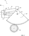
- FIG. 1 shows a tester P for testing or testing a test object R, where FIG. 2 an associated side view of in FIG. 1 shown testing device P shows.
- the test apparatus P will be described below with reference to the common FIGS. 1 and 2 described.
- test device P is useful for imaging / simulation of this (main) engine order.
- the test apparatus P comprises a crank rocker construction K and a gear construction Z1, Z2.
- the crank rocking structure K serves to generate rotational nonuniformity and to transmit rotational nonuniformity to the gear train Z1, Z2.
- crank rocker construction K is coupled on the output side to the gearbox construction Z1, Z2, the gearbox construction Z1, Z2 having at least two mutually engaging toothed elements Z1, Z2, namely a drive-side toothed element Z1 and a driven-side toothed element Z2.
- the gear construction Z1, Z2 can have a ratio adjustment device, by means of which different ratios can be displayed, so that different rotational irregularities for the test object R can be generated.
- the type of engine order can be set (that is, for example, whether 0.5, 1., 2., etc.).
- the crank rocker K comprises three crank arms 1, 2 and 3.
- the three crank arms 1, 2 and 3 are coupled to each other via two substantially parallel axes of rotation A1 and A2.
- a first crank arm 1 is coupled to the toothed element Z1 via a first rotational axis A3, and a second crank arm 2 is likewise coupled to the toothed element Z1 via a second rotational axis A4.
- the first crank arm 1 and the second crank arm 2 are however, spaced apart from each other and thus coupled with an eccentricity E to the toothed element Z1.
- the first rotation axis A3 and the second rotation axis A3 may extend parallel or obliquely to each other.
- the test apparatus P may comprise a setting construction, by means of which different amplitudes can be generated.
- the amplitudes refer to the rotational irregularity generated by the crank rocking structure K.
- the adjustment construction can, for. Example, be realized by the first crank arm 1 and / or the second crank arm 2 is coupled via a slot construction or a multi-hole hole pattern to the tooth element Z1, whereby the eccentricity E is adjustable, in particular can be increased and decreased.
- a third crank arm 3 connects the first crank arm 1 with the second crank arm 2.
- the toothed element Z2 is connected to a shaft W, via which the rotational nonuniformity can be transmitted to the test object R.
- the shaft W is in particular a shaft W with pulley S for coupling the belt drive R.
- the shaft W is preferably designed as a shaft W with freewheel, so that preferably the rotational non-uniformity in only one direction on the test object R is transferable.
Landscapes
- Physics & Mathematics (AREA)
- General Physics & Mathematics (AREA)
- Health & Medical Sciences (AREA)
- Life Sciences & Earth Sciences (AREA)
- Chemical & Material Sciences (AREA)
- Analytical Chemistry (AREA)
- Biochemistry (AREA)
- General Health & Medical Sciences (AREA)
- Immunology (AREA)
- Pathology (AREA)
- Testing Of Devices, Machine Parts, Or Other Structures Thereof (AREA)
Abstract
Description
- Die Erfindung betrifft eine Prüfvorrichtung zur Prüfung oder Erprobung eines Prüfgegenstands, insbesondere eines Riementriebs.
- Zur Prüfung oder Erprobung von in Kraftfahrzeugen eingesetzten Riementrieben, z. B. Keil- und Keilrippenriemen, ist es wesentlich, dass die im Kraftfahrzeug auftretenden Betriebsbedingungen reproduzierbar und realitätsnah nachgebildet werden können. Eine wesentliche Schwierigkeit besteht hierbei darin, Drehungleichförmigkeiten reproduzierbar und realitätsnah nachzubilden. Ein Einzylinder-Viertaktmotor z. B. benötigt zwei Kurbelwellenumdrehungen, um ein Arbeitsspiel zu durchlaufen. Dies bedeutet, dass alle 720 ° Kurbelwinkel gezündet und die Kurbelwelle beschleunigt wird. Die dadurch entstehenden Schwingungen, insbesondere Torsionsschwingungen, werden als Hauptmotorordnung bezeichnet und haben Drehungleichförmigkeiten zur Folge. Die Ordnungszahl von selbiger hängt von den Ereignissen pro Kurbelwellenumdrehung ab. Die Hauptmotorordnung bei z. B. einem Einzylinder-Viertaktmotor ist die 0,5.
- Aus der Praxis ist bekannt, Drehungleichförmigkeiten durch sogenannte vollvariable, hochdynamische Elektromotoren zu erzeugen. Derartige Elektromotoren sind allerdings relativ teuer.
- Eine Aufgabe der Erfindung ist es, eine Prüfvorrichtung zur Prüfung oder Erprobung eines Prüfgegenstands, z. B. eines Riementriebs, zu schaffen, die relativ kostengünstig ist und vorzugsweise darüber hinaus unterschiedliche Drehungleichförmigkeiten erzeugen kann.
- Diese Aufgabe kann mit den Merkmalen des unabhängigen Anspruchs gelöst werden. Vorteilhafte Weiterbildungen der Erfindung können den Unteransprüchen und der folgenden Beschreibung bevorzugter Ausführungsformen der Erfindung entnommen werden.
- Die Erfindung schafft eine Prüfvorrichtung, insbesondere einen Prüfstand, zur Prüfung oder Erprobung eines Prüfgegenstands, insbesondere eines Riementriebs.
- Die Prüfvorrichtung zeichnet sich insbesondere dadurch aus, dass sie eine Kurbelschwingenkonstruktion und eine Getriebekonstruktion aufweist. Die Kurbelschwingenkonstruktion dient insbesondere zur Erzeugung einer Drehungleichförmigkeit und zur Übertragung der Drehungleichförmigkeit auf die Getriebekonstruktion.
- Die Erfindung ermöglicht vorzugsweise, aus einer z. B. durch einen Elektromotor erzeugbaren gleichförmigen Drehbewegung unterschiedliche Drehungleichförmigkeiten zu generieren und dadurch zweckmäßig unterschiedliche Motorordnungen abzubilden.
- Hieraus ergibt sich z. B. einer oder mehrere der folgenden Vorteile:
- Abbildung verschiedener Motorordnungen
- dauerfest
- kostengünstig
- Die Kurbelschwingenkonstruktion ist zweckmäßig abtriebseitig an die Getriebekonstruktion gekoppelt.
- Die Getriebekonstruktion umfasst vorzugsweise zumindest zwei miteinander in Eingriff stehende Verzahnungselemente, z. B. zumindest zwei Zahnradstrukturen.
- Die Getriebekonstruktion kann z. B. eine Übersetzungsverstelleinrichtung aufweisen, um unterschiedliche Übersetzungen zu realisieren, so dass unterschiedliche Drehungleichförmigkeiten für den Prüfgegenstand erzeugbar sind.
- Die Prüfvorrichtung umfasst vorzugsweise einen Elektromotor zum Antrieb der Kurbelschwingenkonstruktion, wobei der Elektromotor vorzugsweise eine gleichförmige Drehbewegung auf die Kurbelschwingenkonstruktion aufbringt.
- Die Kurbelschwingenkonstruktion kann z. B. zumindest drei Kurbelarme umfassen.
- Die zumindest drei Kurbelarme können über vorzugsweise zumindest zwei Drehachsen aneinander gekoppelt sein, die sich z. B. im Wesentlichen parallel zueinander erstrecken.
- Die Prüfvorrichtung kann z. B. eine Einstellkonstruktion (vorzugsweise eine Langlochkonstruktion oder ein mehrere Löcher aufweisendes Lochbild) aufweisen, um unterschiedliche Amplituden der durch die Kurbelschwingenkonstruktion generierten Drehungleichförmigkeit zu erzeugen.
- Es ist möglich, dass ein erster Kurbelarm über eine erste Drehachse und ein zweiter Kurbelarm über eine zweite Drehachse an ein z. B. antriebseitiges Verzahnungselement der Getriebekonstruktion gekoppelt sind, vorzugsweise beabstandet voneinander und somit mit einer Exzentrizität.
- Die erste Drehachse und die zweite Drehachse können sich z. B. im Wesentlichen parallel oder schräg zueinander erstrecken.
- Der erste Kurbelarm und/oder der zweite Kurbelarm können über eine Einstellkonstruktion, z. B. eine Langlochkonstruktion oder ein mehrere Löcher aufweisendes Lochbild, an das vorzugsweise antriebseitige Verzahnungselement gekoppelt sein, um die Exzentrizität verändern zu können, insbesondere zwischen der ersten Drehachse und der zweiten Drehachse. Dadurch können z. B. unterschiedliche Amplituden der durch die Kurbelschwingenkonstruktion generierten Drehungleichförmigkeit erzeugt werden.
- Es ist möglich, dass ein dritter Kurbelarm den ersten Kurbelarm mit dem zweiten Kurbelarm verbindet.
- Die Getriebekonstruktion kann zweckmäßig abtriebseitig mit einer Welle verbunden sein, über die die Drehungleichförmigkeit auf den Prüfgegenstand übertragbar ist, vorzugsweise eine Welle mit Riemenscheibe zur Ankopplung eines Riementriebs.
- Die Welle kann vorzugsweise als Welle mit Freilauf ausgeführt sein, so dass z. B. die Drehungleichförmigkeit nur in eine Richtung auf den Prüfgegenstand übertragbar ist.
- Das Merkmal "Verzahnungselement" kann im Rahmen der Erfindung z. B. ein Zahnrad umfassen, aber auch z. B. ein Element mit einer Verzahnung auf nur einem Kreisbogen und/oder andere Verzahnungsstrukturen.
- Die zuvor beschriebenen Ausführungsformen und Merkmale der Erfindung sind miteinander kombinierbar. Andere vorteilhafte Weiterbildungen der Erfindung sind in den Unteransprüchen offenbart oder ergeben sich aus der folgenden Beschreibung bevorzugter Ausführungsformen der Erfindung in Verbindung mit den beigefügten Figuren.
- Figur 1
- zeigt eine Vorderansicht einer Prüfvorrichtung gemäß einer Ausführungsform der Erfindung, und
- Figur 2
- zeigt eine Seitenansicht der Prüfvorrichtung der
Figur 1 . -
Figur 1 zeigt eine Prüfvorrichtung P zur Prüfung oder Erprobung eines Prüfgegenstands R, wobeiFigur 2 eine zugehörige Seitenansicht der inFigur 1 gezeigten Prüfvorrichtung P zeigt. Die Prüfvorrichtung P wird nachfolgend unter gemeinsamer Bezugnahme auf dieFiguren 1 und2 beschrieben. - Im Betrieb von Verbrennungsmotoren entstehen durch die Zündung des Kraftstoffs charakteristische (Torsions-) Schwingungen, die als (Haupt-) Motorordnung bezeichnet werden und Drehungleichförmigkeiten zur Folge haben. Die Prüfvorrichtung P dient zweckmäßig zur Abbildung/Simulierung dieser (Haupt-) Motorordnung.
- Die Prüfvorrichtung P umfasst eine Kurbelschwingenkonstruktion K und eine Getriebekonstruktion Z1, Z2. Die Kurbelschwingenkonstruktion K dient zur Erzeugung einer Drehungleichförmigkeit und zur Übertragung der Drehungleichförmigkeit auf die Getriebekonstruktion Z1,Z2.
- Die Kurbelschwingenkonstruktion K ist abtriebseitig an die Getriebekonstruktion Z1, Z2 gekoppelt ist, wobei die Getriebekonstruktion Z1, Z2 zumindest zwei miteinander in Eingriff stehende Verzahnungselemente Z1, Z2 aufweist, nämlich ein antriebseitiges Verzahnungselement Z1 und ein abtriebseitiges Verzahnungselement Z2.
- Die Getriebekonstruktion Z1, Z2 kann eine Übersetzungsverstelleinrichtung aufweisen, mittels der unterschiedliche Übersetzungen darstellbar sind, so dass unterschiedliche Drehungleichförmigkeiten für den Prüfgegenstand R erzeugbar sind.
- Durch die Übersetzung (i) der Verzahnungselemente Z1, Z2 kann die Art der Motorordnung eingestellt werden (also z. B. ob 0,5. 1., 2., usw.).
- Der Antrieb der Prüfvorrichtung P, insbesondere der Kurbelschwingenkonstruktion K, erfolgt über einen Elektromotor E, der eine im Wesentlichen gleichförmige Drehbewegung auf die Kurbelschwingenkonstruktion K aufbringt.
- Die Kurbelschwingenkonstruktion K umfasst drei Kurbelarme 1, 2 und 3. Die drei Kurbelarme 1, 2 und 3 sind über zwei im Wesentlichen parallel verlaufende Drehachsen A1 und A2 aneinander gekoppelt.
- Ein erster Kurbelarm 1 ist über eine erste Drehachse A3 an das Verzahnungselement Z1 gekoppelt und ein zweiter Kurbelarm 2 ist über eine zweite Drehachse A4 ebenfalls an das Verzahnungselement Z1 gekoppelt. Der erste Kurbelarm 1 und der zweite Kurbelarm 2 sind allerdings beabstandet voneinander und somit mit einer Exzentrizität E an das Verzahnungselement Z1 gekoppelt. Die erste Drehachse A3 und die zweite Drehachse A3 können sich parallel oder schräg zueinander erstrecken.
- Die Prüfvorrichtung P kann eine Einstellkonstruktion umfassen, mittels der unterschiedliche Amplituden erzeugbar sind. Die Amplituden beziehen sich auf die durch die Kurbelschwingenkonstruktion K generierte Drehungleichförmigkeit.
- Die Einstellkonstruktion kann z. B. realisiert werden, indem der erste Kurbelarm 1 und/oder der zweite Kurbelarm 2 über eine Langlochkonstruktion oder ein mehrere Löcher umfassendes Lochbild an das Verzahnungselement Z1 gekoppelt wird, wodurch die Exzentrizität E verstellbar ist, insbesondere vergrößert und verkleinert werden kann.
- Ein dritter Kurbelarm 3 verbindet den ersten Kurbelarm 1 mit dem zweiten Kurbelarm 2.
- Das Verzahnungselement Z2 ist mit einer Welle W verbunden, über die die Drehungleichförmigkeit auf den Prüfgegenstand R übertragbar ist. Die Welle W ist insbesondere eine Welle W mit Riemenscheibe S zur Ankopplung des Riementriebs R.
- Die Welle W ist vorzugsweise als Welle W mit Freilauf ausgeführt, so dass vorzugsweise die Drehungleichförmigkeit in nur eine Richtung auf den Prüfgegenstand R übertragbar ist.
- Die Erfindung ist nicht auf die oben beschriebenen bevorzugten Ausführungsformen beschränkt. Vielmehr ist eine Vielzahl von Varianten und Abwandlungen möglich, die ebenfalls von dem Erfindungsgedanken Gebrauch machen und deshalb in den Schutzbereich fallen. Darüber hinaus beansprucht die Erfindung auch Schutz für den Gegenstand und die Merkmale der Unteransprüche unabhängig von den in Bezug genommenen Merkmalen und Ansprüchen.
-
- 1
- Kurbelarm
- 2
- Kurbelarm
- 3
- Kurbelarm
- A1
- Drehachse
- A2
- Drehachse
- A3
- Drehachse
- A4
- Drehachse
- E
- Exzentrizität
- M
- Elektromotor
- K
- Kurbelschwingenkonstruktion
- P
- Prüfvorrichtung
- R
- Prüfgegenstand, insbesondere Riementrieb
- S
- Riemenscheibe
- W
- Welle
- Z1
- Verzahnungselement
- Z2
- Verzahnungselement
Claims (13)
- Prüfvorrichtung (P) zur Prüfung oder Erprobung eines Prüfgegenstands (R), vorzugsweise eines Riementriebs (R), dadurch gekennzeichnet, dass die Prüfvorrichtung (P) eine Kurbelschwingenkonstruktion (K) und eine Getriebekonstruktion (Z1, Z2) umfasst und die Kurbelschwingenkonstruktion (K) zur Erzeugung einer Drehungleichförmigkeit und zur Übertragung der Drehungleichförmigkeit auf die Getriebekonstruktion (Z1, Z2) dient.
- Prüfvorrichtung (P) nach Anspruch 1, dadurch gekennzeichnet, dass die Kurbelschwingenkonstruktion (K) abtriebseitig an die Getriebekonstruktion (Z1, Z2) gekoppelt ist und die Getriebekonstruktion (Z1, Z2) zumindest zwei miteinander in Eingriff stehende Verzahnungselemente (Z1, Z2) umfasst.
- Prüfvorrichtung (P) nach Anspruch 1 oder 2, dadurch gekennzeichnet, dass die Getriebekonstruktion (Z1, Z2) eine Übersetzungsverstelleinrichtung umfasst, um unterschiedliche Übersetzungen zu realisieren, so dass unterschiedliche Drehungleichförmigkeiten für den Prüfgegenstand (R) erzeugbar sind.
- Prüfvorrichtung (P) nach einem der vorhergehenden Ansprüche, dadurch gekennzeichnet, dass die Prüfvorrichtung (P) einen Elektromotor (M) zum Antrieb der Kurbelschwingenkonstruktion (K) umfasst, wobei vorzugsweise der Elektromotor (M) eine gleichförmige Drehbewegung auf die Kurbelschwingenkonstruktion (K) aufbringt.
- Prüfvorrichtung (P) nach einem der vorhergehenden Ansprüche, dadurch gekennzeichnet, dass die Kurbelschwingenkonstruktion (K) zumindest drei Kurbelarme (1, 2, 3) umfasst.
- Prüfvorrichtung (P) nach Anspruch 5, dadurch gekennzeichnet, dass die drei Kurbelarme (1, 2, 3) über zumindest zwei Drehachsen (A1, A2) aneinander gekoppelt sind, die sich vorzugsweise parallel zueinander erstrecken.
- Prüfvorrichtung (P) nach einem der vorhergehenden Ansprüche, dadurch gekennzeichnet, dass die Prüfvorrichtung (P) eine Einstellkonstruktion umfasst, um unterschiedliche Amplituden der durch die Kurbelschwingenkonstruktion (K) generierten Drehungleichförmigkeit zu erzeugen.
- Prüfvorrichtung (P) nach einem der vorhergehenden Ansprüche, dadurch gekennzeichnet, dass ein erster Kurbelarm (1) über eine erste Drehachse (A3) und ein zweiter Kurbelarm (2) über eine zweite Drehachse (A4) an ein antriebseitiges Verzahnungselement (Z1) der Getriebekonstruktion (Z1, Z2) gekoppelt sind und zwar beabstandet voneinander und somit mit einer Exzentrizität (E).
- Prüfvorrichtung (P) nach Anspruch 8, dadurch gekennzeichnet, dass die erste Drehachse (A3) und die zweite Drehachse (A4) sich parallel oder schräg zueinander erstrecken.
- Prüfvorrichtung (P) nach Anspruch 8 oder 9, dadurch gekennzeichnet, dass der erste Kurbelarm (1) und/oder der zweite Kurbelarm (2) über eine Einstellkonstruktion, vorzugsweise eine Langlochkonstruktion oder ein mehrere Löcher aufweisendes Lochbild, an das antriebseitige Verzahnungselement (Z1) der Getriebekonstruktion (Z1, Z2) gekoppelt ist, um eine Exzentrizität (E) verstellen zu können, so dass unterschiedliche Amplituden der durch die Kurbelschwingenkonstruktion (K) generierten Drehungleichförmigkeit erzeugbar sind.
- Prüfvorrichtung (P) nach einem der Ansprüche 8 bis 10, dadurch gekennzeichnet, dass ein dritter Kurbelarm (3) den ersten Kurbelarm (1) mit dem zweiten Kurbelarm (2) verbindet.
- Prüfvorrichtung (P) nach einem der vorhergehenden Ansprüche, dadurch gekennzeichnet, dass die Getriebekonstruktion (Z1, Z2) mit einer Welle (W) verbunden ist, über die die Drehungleichförmigkeit auf den Prüfgegenstand (R) übertragbar ist, vorzugsweise eine Welle (W) mit Riemenscheibe (S) zur Ankopplung eines Riementriebs (R).
- Prüfvorrichtung (P) nach Anspruch 12, dadurch gekennzeichnet, dass die Welle (W) als Welle (W) mit Freilauf ausgeführt ist, so dass vorzugsweise die Drehungleichförmigkeit in nur einer Richtung auf den Prüfgegenstand (R) übertragbar ist.
Priority Applications (1)
| Application Number | Priority Date | Filing Date | Title |
|---|---|---|---|
| EP19214455.8A EP3640624A1 (de) | 2016-08-03 | 2017-07-25 | Prüfvorrichtung zur prüfung oder erprobung eines prüfgegenstands |
Applications Claiming Priority (1)
| Application Number | Priority Date | Filing Date | Title |
|---|---|---|---|
| DE102016009457.5A DE102016009457A1 (de) | 2016-08-03 | 2016-08-03 | Prüfvorrichtung zur Prüfung oder Erprobung eines Prüfgegenstands |
Related Child Applications (2)
| Application Number | Title | Priority Date | Filing Date |
|---|---|---|---|
| EP19214455.8A Division-Into EP3640624A1 (de) | 2016-08-03 | 2017-07-25 | Prüfvorrichtung zur prüfung oder erprobung eines prüfgegenstands |
| EP19214455.8A Division EP3640624A1 (de) | 2016-08-03 | 2017-07-25 | Prüfvorrichtung zur prüfung oder erprobung eines prüfgegenstands |
Publications (2)
| Publication Number | Publication Date |
|---|---|
| EP3279633A1 true EP3279633A1 (de) | 2018-02-07 |
| EP3279633B1 EP3279633B1 (de) | 2020-06-17 |
Family
ID=59399297
Family Applications (2)
| Application Number | Title | Priority Date | Filing Date |
|---|---|---|---|
| EP17182909.6A Active EP3279633B1 (de) | 2016-08-03 | 2017-07-25 | Prüfvorrichtung zur prüfung oder erprobung eines prüfgegenstands |
| EP19214455.8A Withdrawn EP3640624A1 (de) | 2016-08-03 | 2017-07-25 | Prüfvorrichtung zur prüfung oder erprobung eines prüfgegenstands |
Family Applications After (1)
| Application Number | Title | Priority Date | Filing Date |
|---|---|---|---|
| EP19214455.8A Withdrawn EP3640624A1 (de) | 2016-08-03 | 2017-07-25 | Prüfvorrichtung zur prüfung oder erprobung eines prüfgegenstands |
Country Status (3)
| Country | Link |
|---|---|
| EP (2) | EP3279633B1 (de) |
| DE (1) | DE102016009457A1 (de) |
| HU (1) | HUE049720T2 (de) |
Cited By (1)
| Publication number | Priority date | Publication date | Assignee | Title |
|---|---|---|---|---|
| CN112129529A (zh) * | 2020-09-01 | 2020-12-25 | 涡阳县信隆船舶附件有限公司 | 一种船舶安全检测装置 |
Citations (6)
| Publication number | Priority date | Publication date | Assignee | Title |
|---|---|---|---|---|
| DE731259C (de) * | 1938-10-26 | 1943-02-04 | Siemens Ag | Schwingungspruefmaschine, auf der ein mit dem Pruefling verbundener Hilfskoerper einer Drehschwingungsbeanspruchung unterworfen wird |
| US3031886A (en) * | 1957-08-14 | 1962-05-01 | Lars E Larsson | Apparatus for and method of fatigue testing materials |
| DE19925540A1 (de) * | 1999-06-04 | 2000-12-21 | Univ Magdeburg Tech | Prüfeinrichtung für Radial- und Axialwellendichtungen |
| DE102006044237A1 (de) * | 2006-09-15 | 2008-03-27 | DÖKA Maschinenbau GmbH & Co. KG | Vorrichtung zur mechanischen Prüfung von Zahnbürsten |
| DE102008013194A1 (de) * | 2008-03-07 | 2009-10-08 | GIF Gesellschaft für Industrieforschung mbH | Axialbelastungsprüfstand |
| CN105043768A (zh) * | 2015-06-30 | 2015-11-11 | 黄山协同轴承有限公司 | 单向轴承耐久试验机 |
Family Cites Families (4)
| Publication number | Priority date | Publication date | Assignee | Title |
|---|---|---|---|---|
| US2603084A (en) * | 1949-06-29 | 1952-07-15 | Goodrich Co B F | Belt testing apparatus |
| GB1429780A (en) * | 1972-12-13 | 1976-03-24 | Uniroyal Ltd | Menas for testing toothed transmission members |
| DE3604653A1 (de) * | 1986-02-14 | 1987-08-27 | Optimol Instr Gmbh | Vorrichtung zur untersuchung des verhaltens kontraformer kontakte |
| DE102014103148A1 (de) * | 2014-03-10 | 2015-09-10 | Martin Maus | Drehschwingungsprüfstand |
-
2016
- 2016-08-03 DE DE102016009457.5A patent/DE102016009457A1/de not_active Withdrawn
-
2017
- 2017-07-25 HU HUE17182909A patent/HUE049720T2/hu unknown
- 2017-07-25 EP EP17182909.6A patent/EP3279633B1/de active Active
- 2017-07-25 EP EP19214455.8A patent/EP3640624A1/de not_active Withdrawn
Patent Citations (6)
| Publication number | Priority date | Publication date | Assignee | Title |
|---|---|---|---|---|
| DE731259C (de) * | 1938-10-26 | 1943-02-04 | Siemens Ag | Schwingungspruefmaschine, auf der ein mit dem Pruefling verbundener Hilfskoerper einer Drehschwingungsbeanspruchung unterworfen wird |
| US3031886A (en) * | 1957-08-14 | 1962-05-01 | Lars E Larsson | Apparatus for and method of fatigue testing materials |
| DE19925540A1 (de) * | 1999-06-04 | 2000-12-21 | Univ Magdeburg Tech | Prüfeinrichtung für Radial- und Axialwellendichtungen |
| DE102006044237A1 (de) * | 2006-09-15 | 2008-03-27 | DÖKA Maschinenbau GmbH & Co. KG | Vorrichtung zur mechanischen Prüfung von Zahnbürsten |
| DE102008013194A1 (de) * | 2008-03-07 | 2009-10-08 | GIF Gesellschaft für Industrieforschung mbH | Axialbelastungsprüfstand |
| CN105043768A (zh) * | 2015-06-30 | 2015-11-11 | 黄山协同轴承有限公司 | 单向轴承耐久试验机 |
Cited By (1)
| Publication number | Priority date | Publication date | Assignee | Title |
|---|---|---|---|---|
| CN112129529A (zh) * | 2020-09-01 | 2020-12-25 | 涡阳县信隆船舶附件有限公司 | 一种船舶安全检测装置 |
Also Published As
| Publication number | Publication date |
|---|---|
| EP3279633B1 (de) | 2020-06-17 |
| EP3640624A1 (de) | 2020-04-22 |
| DE102016009457A1 (de) | 2018-02-08 |
| HUE049720T2 (hu) | 2020-10-28 |
Similar Documents
| Publication | Publication Date | Title |
|---|---|---|
| EP2264422B1 (de) | Prüfstandsanordnung | |
| DE4328537C2 (de) | Getriebeprüfstand und Verfahren zum Prüfen eines Getriebes | |
| EP2264421B1 (de) | Prüfstandsanordnung | |
| EP2082207A2 (de) | Belastungsvorrichtung für einen prüfstand | |
| EP1749194A1 (de) | Prüfstand für brennkraftmaschinen | |
| DE102012021007A1 (de) | Getriebeprüfstand und Verfahren zum Betreiben eines Getriebeprüfstandes | |
| EP0274052A1 (de) | Vorrichtung zur Erzeugung definierter Drehschwingungen in einem mechanischen Getriebe | |
| EP3279633B1 (de) | Prüfvorrichtung zur prüfung oder erprobung eines prüfgegenstands | |
| DE102014103148A1 (de) | Drehschwingungsprüfstand | |
| DE3737602A1 (de) | Einrichtung zum veraendern der steuerzeiten der ventile einer verbrennungskraftmaschine mittels eines differentialgetriebes | |
| DE102010001534B4 (de) | Verfahren zur Bestimmung mindestens eines aussetzenden Zylinders einer Brennkraftmaschine, Steuergerät und Kraftfahrzeugtriebstrang | |
| DE10234022A1 (de) | Modularer Prüfstand für Getriebe, Antriebe oder dergleichen | |
| DE10038281A1 (de) | Verfahren und Vorrichtung zur Reduktion von Schwingungen in einem Antriebssystem, sowie Steuereinrichtung für ein Antriebssystem | |
| DE102013202706A1 (de) | Anordnung für einen Getriebelastprüfstand | |
| DE19751452A1 (de) | Verfahren zum Betrieb eines Lastprüfstandes | |
| DE102010022674B4 (de) | Antriebsvorrichtung für ein Kraftfahrzeug | |
| DE102010022544B4 (de) | Vorrichtung zum Ausgleich der freien Massenkräfte und Massenmomente bei Brennkraftmaschinen mit einem geteilt ausgeführten Kurbeltrieb | |
| DE102021113652B3 (de) | Verfahren zum Betreiben einer Antriebseinrichtung sowie entsprechende Antriebseinrichtung | |
| EP1333268A2 (de) | Verfahren und Vorrichtung zum Prüfen eines Fahrzeug-Antriebsstranges | |
| AT7502U1 (de) | Grundtriebwerk für einen verbrennungsmotor | |
| DE102017101709B4 (de) | Modularer Einzylinder-Prüfstandsmotor und Kurbelgehäuse für diesen Motor | |
| DE102014225446A1 (de) | Getriebeprüfstand für Luftfahrzeuggetriebe | |
| DE102013211203A1 (de) | Getriebevorrichtung zur Erzeugung einer ungleichförmigen Drehbewegung | |
| DE4239096A1 (de) | Antriebsmaschine zur Simulation von Verbrennungsmotoren | |
| DE102012000836A1 (de) | Getriebeprüfstandeinrichtung für Getriebe, insbesondere für Windkraftanlagen, mit einem im Antriebsstrang integrierten Generator |
Legal Events
| Date | Code | Title | Description |
|---|---|---|---|
| PUAI | Public reference made under article 153(3) epc to a published international application that has entered the european phase |
Free format text: ORIGINAL CODE: 0009012 |
|
| STAA | Information on the status of an ep patent application or granted ep patent |
Free format text: STATUS: THE APPLICATION HAS BEEN PUBLISHED |
|
| AK | Designated contracting states |
Kind code of ref document: A1 Designated state(s): AL AT BE BG CH CY CZ DE DK EE ES FI FR GB GR HR HU IE IS IT LI LT LU LV MC MK MT NL NO PL PT RO RS SE SI SK SM TR |
|
| AX | Request for extension of the european patent |
Extension state: BA ME |
|
| STAA | Information on the status of an ep patent application or granted ep patent |
Free format text: STATUS: REQUEST FOR EXAMINATION WAS MADE |
|
| 17P | Request for examination filed |
Effective date: 20180806 |
|
| RBV | Designated contracting states (corrected) |
Designated state(s): AL AT BE BG CH CY CZ DE DK EE ES FI FR GB GR HR HU IE IS IT LI LT LU LV MC MK MT NL NO PL PT RO RS SE SI SK SM TR |
|
| STAA | Information on the status of an ep patent application or granted ep patent |
Free format text: STATUS: EXAMINATION IS IN PROGRESS |
|
| RAP1 | Party data changed (applicant data changed or rights of an application transferred) |
Owner name: MAN TRUCK & BUS SE |
|
| 17Q | First examination report despatched |
Effective date: 20190626 |
|
| REG | Reference to a national code |
Ref country code: DE Ref legal event code: R079 Ref document number: 502017005706 Country of ref document: DE Free format text: PREVIOUS MAIN CLASS: G01M0013020000 Ipc: G01M0013023000 |
|
| RIC1 | Information provided on ipc code assigned before grant |
Ipc: G01M 13/023 20190101AFI20191217BHEP Ipc: G01M 13/025 20190101ALI20191217BHEP Ipc: G01N 3/32 20060101ALI20191217BHEP |
|
| GRAP | Despatch of communication of intention to grant a patent |
Free format text: ORIGINAL CODE: EPIDOSNIGR1 |
|
| STAA | Information on the status of an ep patent application or granted ep patent |
Free format text: STATUS: GRANT OF PATENT IS INTENDED |
|
| INTG | Intention to grant announced |
Effective date: 20200207 |
|
| GRAS | Grant fee paid |
Free format text: ORIGINAL CODE: EPIDOSNIGR3 |
|
| GRAA | (expected) grant |
Free format text: ORIGINAL CODE: 0009210 |
|
| STAA | Information on the status of an ep patent application or granted ep patent |
Free format text: STATUS: THE PATENT HAS BEEN GRANTED |
|
| AK | Designated contracting states |
Kind code of ref document: B1 Designated state(s): AL AT BE BG CH CY CZ DE DK EE ES FI FR GB GR HR HU IE IS IT LI LT LU LV MC MK MT NL NO PL PT RO RS SE SI SK SM TR |
|
| REG | Reference to a national code |
Ref country code: GB Ref legal event code: FG4D Free format text: NOT ENGLISH |
|
| REG | Reference to a national code |
Ref country code: CH Ref legal event code: EP |
|
| REG | Reference to a national code |
Ref country code: DE Ref legal event code: R096 Ref document number: 502017005706 Country of ref document: DE |
|
| REG | Reference to a national code |
Ref country code: IE Ref legal event code: FG4D Free format text: LANGUAGE OF EP DOCUMENT: GERMAN |
|
| REG | Reference to a national code |
Ref country code: AT Ref legal event code: REF Ref document number: 1281898 Country of ref document: AT Kind code of ref document: T Effective date: 20200715 |
|
| REG | Reference to a national code |
Ref country code: NL Ref legal event code: FP |
|
| REG | Reference to a national code |
Ref country code: SE Ref legal event code: TRGR |
|
| REG | Reference to a national code |
Ref country code: HU Ref legal event code: AG4A Ref document number: E049720 Country of ref document: HU |
|
| PG25 | Lapsed in a contracting state [announced via postgrant information from national office to epo] |
Ref country code: LT Free format text: LAPSE BECAUSE OF FAILURE TO SUBMIT A TRANSLATION OF THE DESCRIPTION OR TO PAY THE FEE WITHIN THE PRESCRIBED TIME-LIMIT Effective date: 20200617 Ref country code: GR Free format text: LAPSE BECAUSE OF FAILURE TO SUBMIT A TRANSLATION OF THE DESCRIPTION OR TO PAY THE FEE WITHIN THE PRESCRIBED TIME-LIMIT Effective date: 20200918 Ref country code: NO Free format text: LAPSE BECAUSE OF FAILURE TO SUBMIT A TRANSLATION OF THE DESCRIPTION OR TO PAY THE FEE WITHIN THE PRESCRIBED TIME-LIMIT Effective date: 20200917 Ref country code: FI Free format text: LAPSE BECAUSE OF FAILURE TO SUBMIT A TRANSLATION OF THE DESCRIPTION OR TO PAY THE FEE WITHIN THE PRESCRIBED TIME-LIMIT Effective date: 20200617 |
|
| REG | Reference to a national code |
Ref country code: LT Ref legal event code: MG4D |
|
| PG25 | Lapsed in a contracting state [announced via postgrant information from national office to epo] |
Ref country code: LV Free format text: LAPSE BECAUSE OF FAILURE TO SUBMIT A TRANSLATION OF THE DESCRIPTION OR TO PAY THE FEE WITHIN THE PRESCRIBED TIME-LIMIT Effective date: 20200617 Ref country code: HR Free format text: LAPSE BECAUSE OF FAILURE TO SUBMIT A TRANSLATION OF THE DESCRIPTION OR TO PAY THE FEE WITHIN THE PRESCRIBED TIME-LIMIT Effective date: 20200617 Ref country code: BG Free format text: LAPSE BECAUSE OF FAILURE TO SUBMIT A TRANSLATION OF THE DESCRIPTION OR TO PAY THE FEE WITHIN THE PRESCRIBED TIME-LIMIT Effective date: 20200917 Ref country code: RS Free format text: LAPSE BECAUSE OF FAILURE TO SUBMIT A TRANSLATION OF THE DESCRIPTION OR TO PAY THE FEE WITHIN THE PRESCRIBED TIME-LIMIT Effective date: 20200617 |
|
| PG25 | Lapsed in a contracting state [announced via postgrant information from national office to epo] |
Ref country code: AL Free format text: LAPSE BECAUSE OF FAILURE TO SUBMIT A TRANSLATION OF THE DESCRIPTION OR TO PAY THE FEE WITHIN THE PRESCRIBED TIME-LIMIT Effective date: 20200617 |
|
| PG25 | Lapsed in a contracting state [announced via postgrant information from national office to epo] |
Ref country code: RO Free format text: LAPSE BECAUSE OF FAILURE TO SUBMIT A TRANSLATION OF THE DESCRIPTION OR TO PAY THE FEE WITHIN THE PRESCRIBED TIME-LIMIT Effective date: 20200617 Ref country code: CZ Free format text: LAPSE BECAUSE OF FAILURE TO SUBMIT A TRANSLATION OF THE DESCRIPTION OR TO PAY THE FEE WITHIN THE PRESCRIBED TIME-LIMIT Effective date: 20200617 Ref country code: PT Free format text: LAPSE BECAUSE OF FAILURE TO SUBMIT A TRANSLATION OF THE DESCRIPTION OR TO PAY THE FEE WITHIN THE PRESCRIBED TIME-LIMIT Effective date: 20201019 Ref country code: ES Free format text: LAPSE BECAUSE OF FAILURE TO SUBMIT A TRANSLATION OF THE DESCRIPTION OR TO PAY THE FEE WITHIN THE PRESCRIBED TIME-LIMIT Effective date: 20200617 Ref country code: EE Free format text: LAPSE BECAUSE OF FAILURE TO SUBMIT A TRANSLATION OF THE DESCRIPTION OR TO PAY THE FEE WITHIN THE PRESCRIBED TIME-LIMIT Effective date: 20200617 Ref country code: SM Free format text: LAPSE BECAUSE OF FAILURE TO SUBMIT A TRANSLATION OF THE DESCRIPTION OR TO PAY THE FEE WITHIN THE PRESCRIBED TIME-LIMIT Effective date: 20200617 |
|
| PG25 | Lapsed in a contracting state [announced via postgrant information from national office to epo] |
Ref country code: SK Free format text: LAPSE BECAUSE OF FAILURE TO SUBMIT A TRANSLATION OF THE DESCRIPTION OR TO PAY THE FEE WITHIN THE PRESCRIBED TIME-LIMIT Effective date: 20200617 Ref country code: PL Free format text: LAPSE BECAUSE OF FAILURE TO SUBMIT A TRANSLATION OF THE DESCRIPTION OR TO PAY THE FEE WITHIN THE PRESCRIBED TIME-LIMIT Effective date: 20200617 Ref country code: IS Free format text: LAPSE BECAUSE OF FAILURE TO SUBMIT A TRANSLATION OF THE DESCRIPTION OR TO PAY THE FEE WITHIN THE PRESCRIBED TIME-LIMIT Effective date: 20201017 |
|
| REG | Reference to a national code |
Ref country code: CH Ref legal event code: PL |
|
| REG | Reference to a national code |
Ref country code: DE Ref legal event code: R097 Ref document number: 502017005706 Country of ref document: DE |
|
| PG25 | Lapsed in a contracting state [announced via postgrant information from national office to epo] |
Ref country code: MC Free format text: LAPSE BECAUSE OF FAILURE TO SUBMIT A TRANSLATION OF THE DESCRIPTION OR TO PAY THE FEE WITHIN THE PRESCRIBED TIME-LIMIT Effective date: 20200617 |
|
| PLBE | No opposition filed within time limit |
Free format text: ORIGINAL CODE: 0009261 |
|
| STAA | Information on the status of an ep patent application or granted ep patent |
Free format text: STATUS: NO OPPOSITION FILED WITHIN TIME LIMIT |
|
| REG | Reference to a national code |
Ref country code: BE Ref legal event code: MM Effective date: 20200731 |
|
| PG25 | Lapsed in a contracting state [announced via postgrant information from national office to epo] |
Ref country code: LI Free format text: LAPSE BECAUSE OF NON-PAYMENT OF DUE FEES Effective date: 20200731 Ref country code: LU Free format text: LAPSE BECAUSE OF NON-PAYMENT OF DUE FEES Effective date: 20200725 Ref country code: DK Free format text: LAPSE BECAUSE OF FAILURE TO SUBMIT A TRANSLATION OF THE DESCRIPTION OR TO PAY THE FEE WITHIN THE PRESCRIBED TIME-LIMIT Effective date: 20200617 Ref country code: CH Free format text: LAPSE BECAUSE OF NON-PAYMENT OF DUE FEES Effective date: 20200731 |
|
| 26N | No opposition filed |
Effective date: 20210318 |
|
| PG25 | Lapsed in a contracting state [announced via postgrant information from national office to epo] |
Ref country code: BE Free format text: LAPSE BECAUSE OF NON-PAYMENT OF DUE FEES Effective date: 20200731 Ref country code: SI Free format text: LAPSE BECAUSE OF FAILURE TO SUBMIT A TRANSLATION OF THE DESCRIPTION OR TO PAY THE FEE WITHIN THE PRESCRIBED TIME-LIMIT Effective date: 20200617 |
|
| PG25 | Lapsed in a contracting state [announced via postgrant information from national office to epo] |
Ref country code: IE Free format text: LAPSE BECAUSE OF NON-PAYMENT OF DUE FEES Effective date: 20200725 |
|
| PG25 | Lapsed in a contracting state [announced via postgrant information from national office to epo] |
Ref country code: TR Free format text: LAPSE BECAUSE OF FAILURE TO SUBMIT A TRANSLATION OF THE DESCRIPTION OR TO PAY THE FEE WITHIN THE PRESCRIBED TIME-LIMIT Effective date: 20200617 Ref country code: MT Free format text: LAPSE BECAUSE OF FAILURE TO SUBMIT A TRANSLATION OF THE DESCRIPTION OR TO PAY THE FEE WITHIN THE PRESCRIBED TIME-LIMIT Effective date: 20200617 Ref country code: CY Free format text: LAPSE BECAUSE OF FAILURE TO SUBMIT A TRANSLATION OF THE DESCRIPTION OR TO PAY THE FEE WITHIN THE PRESCRIBED TIME-LIMIT Effective date: 20200617 |
|
| PG25 | Lapsed in a contracting state [announced via postgrant information from national office to epo] |
Ref country code: MK Free format text: LAPSE BECAUSE OF FAILURE TO SUBMIT A TRANSLATION OF THE DESCRIPTION OR TO PAY THE FEE WITHIN THE PRESCRIBED TIME-LIMIT Effective date: 20200617 |
|
| PGFP | Annual fee paid to national office [announced via postgrant information from national office to epo] |
Ref country code: HU Payment date: 20250725 Year of fee payment: 9 |
|
| PGFP | Annual fee paid to national office [announced via postgrant information from national office to epo] |
Ref country code: NL Payment date: 20250724 Year of fee payment: 9 |
|
| PGFP | Annual fee paid to national office [announced via postgrant information from national office to epo] |
Ref country code: DE Payment date: 20250728 Year of fee payment: 9 |
|
| PGFP | Annual fee paid to national office [announced via postgrant information from national office to epo] |
Ref country code: IT Payment date: 20250721 Year of fee payment: 9 |
|
| PGFP | Annual fee paid to national office [announced via postgrant information from national office to epo] |
Ref country code: GB Payment date: 20250722 Year of fee payment: 9 |
|
| PGFP | Annual fee paid to national office [announced via postgrant information from national office to epo] |
Ref country code: FR Payment date: 20250725 Year of fee payment: 9 Ref country code: AT Payment date: 20250718 Year of fee payment: 9 |
|
| PGFP | Annual fee paid to national office [announced via postgrant information from national office to epo] |
Ref country code: SE Payment date: 20250725 Year of fee payment: 9 |