EP3279422B1 - Dosierungsvorrichtung zum extrudieren eines zweikomponentigen oder einkomponentigen dichtungsmittels - Google Patents
Dosierungsvorrichtung zum extrudieren eines zweikomponentigen oder einkomponentigen dichtungsmittels Download PDFInfo
- Publication number
- EP3279422B1 EP3279422B1 EP17184531.6A EP17184531A EP3279422B1 EP 3279422 B1 EP3279422 B1 EP 3279422B1 EP 17184531 A EP17184531 A EP 17184531A EP 3279422 B1 EP3279422 B1 EP 3279422B1
- Authority
- EP
- European Patent Office
- Prior art keywords
- dosage
- flow
- sealant
- assemblies
- assembly
- Prior art date
- Legal status (The legal status is an assumption and is not a legal conclusion. Google has not performed a legal analysis and makes no representation as to the accuracy of the status listed.)
- Active
Links
Images








Classifications
-
- E—FIXED CONSTRUCTIONS
- E06—DOORS, WINDOWS, SHUTTERS, OR ROLLER BLINDS IN GENERAL; LADDERS
- E06B—FIXED OR MOVABLE CLOSURES FOR OPENINGS IN BUILDINGS, VEHICLES, FENCES OR LIKE ENCLOSURES IN GENERAL, e.g. DOORS, WINDOWS, BLINDS, GATES
- E06B3/00—Window sashes, door leaves, or like elements for closing wall or like openings; Layout of fixed or moving closures, e.g. windows in wall or like openings; Features of rigidly-mounted outer frames relating to the mounting of wing frames
- E06B3/66—Units comprising two or more parallel glass or like panes permanently secured together
- E06B3/673—Assembling the units
- E06B3/67339—Working the edges of already assembled units
- E06B3/67343—Filling or covering the edges with synthetic hardenable substances
- E06B3/67347—Filling or covering the edges with synthetic hardenable substances by extrusion techniques
-
- B—PERFORMING OPERATIONS; TRANSPORTING
- B05—SPRAYING OR ATOMISING IN GENERAL; APPLYING FLUENT MATERIALS TO SURFACES, IN GENERAL
- B05C—APPARATUS FOR APPLYING FLUENT MATERIALS TO SURFACES, IN GENERAL
- B05C11/00—Component parts, details or accessories not specifically provided for in groups B05C1/00 - B05C9/00
- B05C11/10—Storage, supply or control of liquid or other fluent material; Recovery of excess liquid or other fluent material
- B05C11/1036—Means for supplying a selected one of a plurality of liquids or other fluent materials, or several in selected proportions, to the applying apparatus
-
- E—FIXED CONSTRUCTIONS
- E06—DOORS, WINDOWS, SHUTTERS, OR ROLLER BLINDS IN GENERAL; LADDERS
- E06B—FIXED OR MOVABLE CLOSURES FOR OPENINGS IN BUILDINGS, VEHICLES, FENCES OR LIKE ENCLOSURES IN GENERAL, e.g. DOORS, WINDOWS, BLINDS, GATES
- E06B3/00—Window sashes, door leaves, or like elements for closing wall or like openings; Layout of fixed or moving closures, e.g. windows in wall or like openings; Features of rigidly-mounted outer frames relating to the mounting of wing frames
- E06B3/66—Units comprising two or more parallel glass or like panes permanently secured together
- E06B3/663—Elements for spacing panes
- E06B3/66309—Section members positioned at the edges of the glazing unit
- E06B3/66314—Section members positioned at the edges of the glazing unit of tubular shape
-
- E—FIXED CONSTRUCTIONS
- E06—DOORS, WINDOWS, SHUTTERS, OR ROLLER BLINDS IN GENERAL; LADDERS
- E06B—FIXED OR MOVABLE CLOSURES FOR OPENINGS IN BUILDINGS, VEHICLES, FENCES OR LIKE ENCLOSURES IN GENERAL, e.g. DOORS, WINDOWS, BLINDS, GATES
- E06B3/00—Window sashes, door leaves, or like elements for closing wall or like openings; Layout of fixed or moving closures, e.g. windows in wall or like openings; Features of rigidly-mounted outer frames relating to the mounting of wing frames
- E06B3/66—Units comprising two or more parallel glass or like panes permanently secured together
- E06B3/663—Elements for spacing panes
- E06B3/66309—Section members positioned at the edges of the glazing unit
- E06B3/66342—Section members positioned at the edges of the glazing unit characterised by their sealed connection to the panes
- E06B3/66352—Section members positioned at the edges of the glazing unit characterised by their sealed connection to the panes with separate sealing strips between the panes and the spacer
-
- E—FIXED CONSTRUCTIONS
- E06—DOORS, WINDOWS, SHUTTERS, OR ROLLER BLINDS IN GENERAL; LADDERS
- E06B—FIXED OR MOVABLE CLOSURES FOR OPENINGS IN BUILDINGS, VEHICLES, FENCES OR LIKE ENCLOSURES IN GENERAL, e.g. DOORS, WINDOWS, BLINDS, GATES
- E06B3/00—Window sashes, door leaves, or like elements for closing wall or like openings; Layout of fixed or moving closures, e.g. windows in wall or like openings; Features of rigidly-mounted outer frames relating to the mounting of wing frames
- E06B3/66—Units comprising two or more parallel glass or like panes permanently secured together
- E06B3/673—Assembling the units
- E06B3/67326—Assembling spacer elements with the panes
- E06B3/6733—Assembling spacer elements with the panes by applying, e.g. extruding, a ribbon of hardenable material on or between the panes
-
- B—PERFORMING OPERATIONS; TRANSPORTING
- B05—SPRAYING OR ATOMISING IN GENERAL; APPLYING FLUENT MATERIALS TO SURFACES, IN GENERAL
- B05C—APPARATUS FOR APPLYING FLUENT MATERIALS TO SURFACES, IN GENERAL
- B05C5/00—Apparatus in which liquid or other fluent material is projected, poured or allowed to flow on to the surface of the work
- B05C5/02—Apparatus in which liquid or other fluent material is projected, poured or allowed to flow on to the surface of the work the liquid or other fluent material being discharged through an outlet orifice by pressure, e.g. from an outlet device in contact or almost in contact, with the work
- B05C5/0204—Apparatus in which liquid or other fluent material is projected, poured or allowed to flow on to the surface of the work the liquid or other fluent material being discharged through an outlet orifice by pressure, e.g. from an outlet device in contact or almost in contact, with the work for applying liquid or other fluent material to the edges of essentially flat articles
-
- E—FIXED CONSTRUCTIONS
- E06—DOORS, WINDOWS, SHUTTERS, OR ROLLER BLINDS IN GENERAL; LADDERS
- E06B—FIXED OR MOVABLE CLOSURES FOR OPENINGS IN BUILDINGS, VEHICLES, FENCES OR LIKE ENCLOSURES IN GENERAL, e.g. DOORS, WINDOWS, BLINDS, GATES
- E06B3/00—Window sashes, door leaves, or like elements for closing wall or like openings; Layout of fixed or moving closures, e.g. windows in wall or like openings; Features of rigidly-mounted outer frames relating to the mounting of wing frames
- E06B3/66—Units comprising two or more parallel glass or like panes permanently secured together
- E06B3/67—Units comprising two or more parallel glass or like panes permanently secured together characterised by additional arrangements or devices for heat or sound insulation or for controlled passage of light
- E06B3/6715—Units comprising two or more parallel glass or like panes permanently secured together characterised by additional arrangements or devices for heat or sound insulation or for controlled passage of light specially adapted for increased thermal insulation or for controlled passage of light
Definitions
- the present invention relates to a dosage device for extruding a bicomponent or monocomponent sealant, particularly for an automatic machine for sealing a perimetric edge of an insulating glazing unit.
- the operation can further be multiple so as to obtain the insulating glazing unit 1 constituted by three glass sheets (2, 2', 2") and two frames (3, 3') or spacer profiles (5, 5'), as well as "n” glass sheets (2, 2', 2", 2"', 2M, 2'm, 2"m) and "n-1" frames (3, 3', 3") or spacer profiles (5, 5', 5").
- the insulating glazing unit (1) is constituted by the composition of two or more glass sheets (2, 2', 2", 2′′′, 2M, 2'm, 2"m), which are separated by one or more spacer frames (3, 3', 3"), generally made of inorganic material, such as for example aluminum or stainless steel or mixed inorganic/organic material, the second one being generally for example made of polyvinyl chloride (PVC), generally hollow and microperforated on the face that is directed inward, the spacer frames (3, 3', 3") containing hygroscopic material (4) in their hollow part and being provided with a butyl sealant (6) (constituting the so-called first seal) on the lateral faces and the chamber (or chambers), delimited by the glass sheets (2, 2', 2", 2′′′, 2M, 2'm, 2"m) and by the spacer frame or frames
- spacer profile (5) having an essentially rectangular cross-section, which optionally contains two receptacles on its two sides intended for the butyl sealant (6), made of synthetic organic material, such as for example silicone and EPDM rubbers (from the English Ethylene-Propylene Diene Monomer), which is expanded, containing hygroscopic material (4) and is provided in its sides or part thereof with an adhesive (6') which is useful for mechanical bonding with the glass sheets.
- synthetic organic material such as for example silicone and EPDM rubbers (from the English Ethylene-Propylene Diene Monomer)
- Joining between the glass sheets (2, 2', 2", 2′′′, 2M, 2'm, 2"m) and the spacer frame or frames (3, 3', 3") or (5, 5', 5") is obtained by means of two sealing levels; the first one (also known in the jargon as primary) (6) having the function of providing a hermetic seal and the initial bonding between said components and affecting the lateral surfaces of the frame and the portions of the adjacent glass sheets, already mentioned earlier (butyl sealant, thermoplastic); the second one (also known in the jargon as secondary) (7), typically constituted by an elastomeric bicomponent sealant, such as polysulfide (PS) or polyurethane (PU) or silicone (SI), processed at room temperature, but also constituted by monocomponent sealant of the type processed at room temperature or of the hot processed type, having the function of providing final cohesion among the components and mechanical strength of the joint between them and affecting the compartment constituted by the outer surface of the spacer frame (3, 5) and by
- the first sealing level is replaced (in this case losing the hermetic sealing function) or can be integrated (in this case preserving the hermetic sealing function) by an adhesive (6'), for example an acrylic adhesive, which is already spread on the lateral faces of said spacer profile and is covered by a removable protective film (see Figure 1D , in which said film has already been removed).
- an adhesive (6') for example an acrylic adhesive, which is already spread on the lateral faces of said spacer profile and is covered by a removable protective film (see Figure 1D , in which said film has already been removed).
- the glass sheets (2, 2', 2", 2′′′, 2M, 2'm, 2"m) used in the composition of the insulating glazing unit (1) can have different shapes as a function of the use thereof; for example, the outer glass sheet (outer being understood with respect to the building) can be normal or reflective or selective (in order to limit the thermal input during summer months) or laminated/armored (for intrusion prevention/vandalism prevention/bulletproof functions) or laminated/tempered (for safety functions) or combined (for example reflective and laminated, in order to obtain a combination of properties), the inner glass sheet (inner being understood with respect to the building) can be normal or low-emissive (in order to limit heat loss during the winter months) or laminated/tempered (for security functions) or combined (for example low-emissive and laminated in order to obtain a combination of properties).
- the invention that is the subject matter of the present application relates in particular to the manner of feeding the sealant (which is bicomponent but also optionally monocomponent) to the extrusion head and nozzle, a manner, that is adapted to provide high flow-rates of the sealant and to eliminate any discontinuity, so as to obtain a high productivity of the line for producing the insulating glazing unit (1) and a high functional and aesthetic quality of the filling of the perimetric joint.
- Machines and methods are known for performing the second sealing in order to provide many inventions, which relate to the solutions for the dosage and feeding of the secondary sealant (7) to the head and therefore to the extrusion nozzle, which we define as of the first type or with flow discontinuity, since the dosage devices of the bicomponent products or the dosage device of the monocomponent product, once the contained product has been depleted, must be reloaded, and this occurs by actuating reloading and discharge valves, entailing that during the reloading step the flow toward the extrusion nozzle is interrupted; in this case, the sealing product is distributed proximate to the rigid spacer profile (3, 3', 3") or to the flexible spacer profile (5, 5', 5") in order to join it mechanically to the glass sheets (2, 2', 2", 2′′′, 2M, 2'm, 2"m) and until alignment occurs with the edges of the glass sheets or with the edge of the smallest glass sheet (2'm, 2"m) (in the case of insulating glazing units with offset glass
- inventions of the first type and inventions of the second type are the flow-rate of the sealing fluid, which is modest and discontinuous in the first case and important and continuous in the second case and is such as to require an additional inventive step with respect to the background art of the first type.
- gear pumps when used to pump products which are viscous and unfortunately non-Newtonian and sometimes corrosive, such as sealants used in the production of insulating glazing units and when intended for high flow-rates, must be manufactured with very particular refinements which often do not provide a solution regarding the choice of materials and of machining tolerances, and this makes them very expensive.
- abrasion and corrosion they have a rather short life and a progressive decay of precision during operation, since bypass paths form between the chamber located downstream of the gears and the chamber located upstream as the plays increase and as channels form.
- a dosage device is known from US2015/028055A1 and US6540104B1 .
- the aim of the present invention is therefore to eliminate the drawbacks of the background art, by providing a device that allows continuity of the sealing process.
- an object of the present invention is to allow to achieve high flow-rates of the sealing fluid and also a lack of discontinuity of extrusion even in the situation of large dimensions (distance between the glass sheets and depth of the sealant) of the joint and of considerable extension of the perimeter.
- Another object is to provide a device that allows to achieve dosage precision and to maintain dosage precision over time, eliminating the problems of the background art of the second type.
- Another object which is not less important but is complementary to the described aim, is to reduce load losses of the fluid in its path from the dosage devices to the extrusion nozzle.
- FIGURES 1A to 1F are schematic views of the peripheral portion of the insulating glazing unit 1 in a non-exhaustive exemplifying series of possible combinations: 1A normal; 1B triple glazing with inner sheet with low-emissivity coating; 1C outer sheet with selective coating and offset with respect to the inner sheet with low-emissivity coating; 1D tempered outer sheet and inner sheet with low-emissivity coating; 1E laminated outer sheet offset with respect to the inner sheet with low-emissivity coating; 1F triple glazing with laminated outer sheet offset with respect to the remaining two glass sheets, the inner one having a low-emissivity coating.
- Figures 1A, 1B, 1C and 1E show the rigid frame (3) made of metal profile (typically aluminum or stainless steel or a combination of stainless steel and plastic), which is hollow and is filled with hygroscopic material (4), while Figures 1D and 1F show the frame of the flexible type (5), which embeds the hygroscopic material (4) in its mass, but for the purposes of the description the solution indicated for the frame is irrelevant.
- metal profile typically aluminum or stainless steel or a combination of stainless steel and plastic
- Figures 1D and 1F show the frame of the flexible type (5), which embeds the hygroscopic material (4) in its mass, but for the purposes of the description the solution indicated for the frame is irrelevant.
- the two types of sealant used are shown in cross-section: in black, the butyl sealant (6), which has the function of an initial bonding between the components and of a hermetic seal (first sealing and primary sealant), in the case of a flexible frame, instead, one uses an acrylic adhesive (6') (which is only indicated but not shown, since it has a thickness of a few ⁇ m) or the combination of the acrylic sealant (6') and of the butyl sealant (6) applied between the receptacles of the lateral surfaces of the frame and the glass sheets, as can be seen in Figures 1D and 1F ; in shading, the polysulfide (PS) or polyurethane (PU) or silicone (SI) sealant (7), which has the function of mechanical coupling to the edge and of hermetic seal (second sealing and secondary sealant) applied between the outer surface of the frame and the faces of the glass sheets up to the edge of the glass sheets or of the glass sheet (2'm) having the smallest dimensions (in the case of offset glass sheets
- the secondary sealant also contributes, albeit less than the primary sealant, to the hermetic seal against the entry of humidity and the escape of the gas (8).
- Figures 1D, 1E and 1F show the cases for which the present invention has an essential relevance, i.e., the cases of large dimensions of the glass sheets and of the joint (both in terms of sides of the glass sheets and in terms of thickness and position of the spacer frames) for which the execution of the joint entrusted to the secondary sealant requires a high and continuous flow-rate at the dosage, mixing, feeding, extrusion devices.
- the inner/outer orientation is identified visually with icons that represent the sun (outer side) and the radiator (inner side).
- the insulating glazing unit (1) can have multiple shapes and that the machines for applying the second seal must be suitable and versatile, for example to seal an insulating glazing unit (1) composed of two glass sheets, a unit composed of three glass sheets, a unit with offset glass sheets, a unit composed of three or more glass sheets one or more of which is larger and therefore offset with respect to the remaining ones, characteristics of machines that are already established in the background art, and these machines must be productive in terms of flow-rate and continuity of filling (to which the present patent application relates) of the peripheral joint with the secondary sealant (7), even when said joint has considerable dimensions in the distance between the two glass sheets and in the distance between the outer surface of the spacer frame and the margin of the glass sheet or sheets having smaller dimensions.
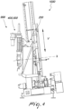
- FIGS 2 , 3 , 4 show the automatic sealing machine (1000), which includes the subject matter of the present invention, respectively in its overall main views: front, from above, from the side, with identification of the horizontal axis H [provided by the means assembly 100 of the known type constituted both by the motorized pseudo-horizontal conveyors that act on the lower edge 1d of the insulating glazing unit (1) and by the carriage with sucker (suckers) (100'), which acts on the face of the insulating glazing unit (1), while the insulating glazing unit (1) remains rested on said motorized pseudo-horizontal conveyors, which are slightly inclined with respect to the horizontal plane, and on a pseudo-vertical sliding surface (900), which is slightly inclined with respect to the vertical plane, provided with free wheels or with an air cushion], of the vertical axis V [assembly (200) of the known type] and of the rotation axis ⁇ [assembly (300) of the known type].
- the means assembly 100 of the known type constituted both by the motorized pseudo-horizon
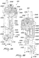
- Figures 5A, 5B , 6A and 6B are opposite axonometric views (for the visibility of all the components) respectively of the first and second dosage assemblies (400, 500), which can be termed "relay”, this term describing their mode of operation, i.e., swapping of the active dosage step between one of the first dosage assembly (400), with dosage devices "A”, “a′′′, and the separate second dosage assembly (500), with dosage devices "B", “b”, without discontinuity of the output flow toward the nozzle and then from the nozzle toward the perimetric cavity of the insulating glazing unit to be sealed.
- delay this term describing their mode of operation, i.e., swapping of the active dosage step between one of the first dosage assembly (400), with dosage devices "A”, “a′′′, and the separate second dosage assembly (500), with dosage devices "B", “b”, without discontinuity of the output flow toward the nozzle and then from the nozzle toward the perimetric cavity of the insulating glazing unit to be sealed.
- the first and second dosage assemblies (400, 500) constitute the dosage device (999), to which the present application relates.
- Figure 7 is the flow-rate chart of each one of the "relay” dosage assemblies in combination with the complementary chart of the other dosage assembly.
- the ordinates plot the cumulative flow-rate “A + a" [base product “A” “+” catalyst product “a” of the first dosage assembly (400)] and the cumulative flow-rate “B + b” [base product “B” “+” catalyst product “b” of the second dosage assembly (500)].
- the absc issas plot time.
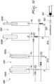
- Figure 8 is the single-line diagram of the circuits of the fluids for the base product "A, B” and catalyst product "a, b" in the interconnection with the first dosage assemblies (400) in the active step and the second dosage assemblies (500) in the reloading step, in the solution using three-way valves for the main circuits.
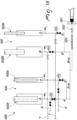
- Figure 9 is the alternative single-line diagram of the circuits of the fluids for the base product "A, B” and catalyst product "a, b" in the interconnection with the first dosage assemblies (400) in the active step and the second dosage assemblies (500) in the reloading step, in the solution using two-way valves, a condition which is more practical and reliable from the systems standpoint.
- Figure 10 is an alternative single-line diagram of the circuits of the fluids for the base product "A, B” and catalyst product "a, b" in the interconnection with the first dosage assemblies (400) in the active step and the second dosage assemblies (500) in the reloading step, in the solution using two-way valves and one-way valves, a condition which is more practical and reliable from the systems standpoint.
- Figure 11 is a view of the logic and power controllers and circuits.
- Figures 12A, 12B, 12C and 12D are views respectively of the insulating glazing unit (1) in its following shapes: rectangular (1), polygonal (1'), curvilinear (1"), mixed (1′′′).
- the sides are designated in the sequence of the sealing operation, which therefore occurs according to the following progression: side (1a), corner (1a/1b), side (1b), corner (1b/1c), side (1c), corner (1c/ld), side (1d), corner (1d/1a).
- Figure 13 is a view of an example of insertion of the automatic sealing machine (1000) in the line for the production of the insulating glazing unit (1) (overall view) and does not comprise: electrical/electronic panel, control post and protection devices.
- Figure 14 is a view of an example of insertion of the automatic sealing machine (1000) in the line for the production of the insulating glazing unit (1) (plan view) and includes: electrical/electronic panel (11), control post (12) and protection devices, which are designated generally by (13), be they of the type of mechanical screens, or optical barriers, or laser barriers, or electrically sensitive mats, or region scanners, etc., since particular attention is given not only to the functional, qualitative and productive aspects that are part of the content of the present invention but also to the aspects related to injury prevention.
- insulating glazing unit (1) glass sheet (2, 2', 2", 2′′′, 2M, 2'm, 2"m), spacer frame (3, 3', 3", 5, 5', 5") and further components thereof are designated by single-digit numbering.
- (1) designates the most frequent situation (rectangular)
- (1') designates the polygonal shape
- (1") designates the curvilinear shape
- (1′′′) designates the mixed shape.
- the components that are interfaced with the automatic sealing unit are designated by two-digit numbering.
- the main components of the inventive device according to the present application (400, 500) and of the known correlated devices are designated by three-digit numbering, wherein the ones containing two zeros are referred to sets or assemblies while the others are referred to the respective details.
- the machines that belong to the line for the production of the insulating glazing unit 1 are designated by four-digit numbering, in the order according to the description, reserving (1000) for the automatic sealing machine.
- Figure 15 is a single-line diagram that embodies an alternative use of the dosage assemblies (400, 500), since each assembly dedicated, independently of the other, to the dosage of a sealant, in the illustration the sealant X (composed of a base A and a catalyst a) is used, in order to be able to feed to the perimetric edge of the insulating glazing unit multiple types of sealant.
- Figure 16 is a single-line diagram that embodies an alternative use of the dosage assemblies (400, 500), since each assembly dedicated, independently of the other, to the dosage of a sealant, in the illustration the sealant Y (composed of a base B and a catalyst b) is used, in order to be able to feed to the perimetric edge of the insulating glazing unit multiple types of sealant.
- Each first and second dosage assembly (400, 500) is constituted by the dosage device of said base product [base product which is correlated to the symbol "A” when used in the first dosage assembly (400) and to the symbol “B” when used in the second dosage assembly (500)] and by the dosage device of said catalyst product [catalyst product which is correlated to the symbol "a” when used in the first dosage assembly (400) and to the symbol “b” when used in the second dosage assembly (500)], which, being each in a synchronous electrical tie, can dispense the flow of base product and the flow of the catalyst product in the stoichiometric ratio required by the manufacturer of the secondary sealant [typically 10:1 by volume, but any ratio can be set by means of simple inputs in the control panel (12)].
- the base product dosage device comprises the following essential components [reference is made to the first dosage assembly (400)]: (401A) plunger or syringe; (402A) cylinder or chamber; (403A) hermetic seal; (404A) ballscrew; (405A) ballscrew sleeve; (406A) mechanical transmission, for example of the type with sprockets and chain; (407A) mechanical reduction unit; (408A) synchronous electric motor. It goes without saying that these components are coupled partly to an upper plate and partly to a lower plate which are connected by tension members, structural elements which are shared and used by the dosage device "A" of the base product and by the dosage device "a” of the catalyst product, as can be seen in Figures 5A and 5B .
- the base product dosage device comprises the following auxiliary components, which are however in any case indispensable [reference is made again to the first dosage assembly (400)]: (409A) three-way valve, which can be replaced by two two-way valves or by a two-way valve and a one-way valve; (410A) pressure transducer; (411A) pressure gauge; (412A) overpressure valve or rupture disk; (413A) manual withdrawal valve (useful to check the stoichiometry of the dosage ratio by weighing quantities withdrawn simultaneously).
- auxiliary components which are however in any case indispensable [reference is made again to the first dosage assembly (400)]: (409A) three-way valve, which can be replaced by two two-way valves or by a two-way valve and a one-way valve; (410A) pressure transducer; (411A) pressure gauge; (412A) overpressure valve or rupture disk; (413A) manual withdrawal valve (useful to check the stoichiometry of the dosage ratio by weighing quantities withdrawn simultaneously).
- the catalyst product dosage device comprises the following essential components [reference is made to the first dosage assembly (400)]: (401a) plunger or syringe; (402a) cylinder or chamber; (403a) hermetic seal; (404a) ballscrew; (405a) ballscrew sleeve; (406a) mechanical transmission, for example of the type with sprockets and chain; (407a) mechanical reduction unit; (408a) synchronous electric motor.
- the catalyst product dosage device comprises the following auxiliary components, which are however in any case indispensable [reference is made again to the first dosage assembly (400)]: (409a) three-way valve, which can be replaced by two two-way valves or by a two-way valve and a one-way valve; (410a) pressure transducer; (411a) pressure gauge; (412a) overpressure valve or rupture disk; (413a) manual withdrawal valve (useful to check the stoichiometry of the dosage ratio by weighing quantities withdrawn simultaneously).
- a particular characteristic of the present invention resides in using the communion of two dosage assemblies: the first dosage assembly (400) composed of the numberings "4_A” and “4_a” and the second dosage assembly (500) composed of the numberings "5_B” and "5_b” (the underscores referencing the variable digits that have already been used previously), all operating with the same sealant (typically PS or PU or SI), said communion being controlled by a swapping logic such as to maintain an active condition at the dosage nozzle (301) that is free from discontinuities, both in terms of flow-rate and in terms of pressure.
- the swapping logic is obtained by acting in a complementary manner on the flow-rates of the first dosage assembly (400) (the uppercase letter “A” designates the base and the lowercase letter “a” designates the catalyst, the symbol “+” being used to indicate the sum of the base and of the catalyst) and of the second dosage assembly (500) (the uppercase letter “B” designates the base and the lowercase letter “b” designates the catalyst, the symbol “+” being used to indicate the sum of the base and of the catalyst) and in a controlled manner on the process pressures.
- the lowercase "a” and lowercase “b” do not exist.
- FIG 8 The single-line diagram of operation of the dosage assemblies is shown in Figure 8 , which shows the condition of the first dosage assembly (400) (A + a) in the step for dispensing toward the nozzle (301) which interacts with the peripheral region of the insulating glazing unit (1) and of the second dosage assembly (500) (B + b) during the reloading step; the shaded part of the symbols that represent the valves indicates the side in the closed state; the corresponding position in the chart or diagram of Figure 7 being the one of the left part with (A + a) at the nominal flow-rate and with (B + b) at nil flow-rate.
- the interrupted part on the left is assumed to be known, constituting respectively the feeding of the base product and of the catalyst product as arriving from the pumps, typically of the double-acting type, arranged on the pressing plates of the product storage drums for their transfer for feeding to the dosage devices, as already disclosed in the cited prior art.
- the background art does not have a solution for the interruption of the flow of the sealant that derives from the depletion of the load of the dosage devices and is forced to perform a sudden transient, in reversing the effect of the double-acting dosage device, which has repercussions in the inaccuracy of the dosage ratio and in the aesthetics of the seal of the edge, said transient increasing in frequency as the cross-section of the joint increases, as the length of the side to be sealed increases and as the volumes of the dosage devices decreases.
- the transducers are arranged directly upstream of the valves (509A) and (509a), in the various versions of solutions for said valves, so that the pressure controls are not affected by the load losses of the circuits upstream thereof.
- controllers such as for example the cross-sections "S1" and “S2" of the syringes, since they are fixed data.
- the first dosage assembly (400) reduces the speeds (c1) and (c2) of the syringes (401A) and (401a) from the nominal values, which correspond to the flow-rate (v ⁇ S) and to the stoichiometric dosage, until they are canceled, while the second dosage assembly (500) moves the syringes (501B) and (501b) from the inactive condition, i.e., with (c1) and (c2) equal to zero, up to the nominal values, which correspond to the flow-rate (v ⁇ S) and to the stoichiometric dosage.
- the functions that control said ramps are such that the sum of the respective flow-rates (A + a + B + b) always corresponds to the nominal flow-rate (v ⁇ S). These functions can be linear or nonlinear.
- controllers (306) shown for the second dosage assembly (500) and the equivalent controller (306') for the first dosage assembly (400) communicate with the operator interface (307) located on board the control post (12).
- the present invention is susceptible of numerous constructive variations (with respect to what can be deduced from the drawings, the details of which are evident and eloquent), all of which are within the scope of the appended claims; thus, for example, the mechanical solutions for the movements of the dosage syringes, the actuation means, which can be electrical, electrical-electronic, pneumatic, oil pressure-operated and/or combined, etc, the control means, which can be electronic or fluidic and/or combined, etc..
- the materials and dimensions may be any according to the requirements in particular arising from the dimensions (base and height) and/or from the shape of the glass sheets (2, 2', 2", 2′′′, 2M, 2'm, 2"m) that will constitute the insulating glazing unit (1).
- each assembly advantageously assigning each assembly to a specific sealing product, typically: polysulfide (PS), polyurethane (PU) and silicone (SI), so as to feed to the perimetric edge of the insulating glazing unit 1 the specific type of sealant (PS or PU or SI) that is required depending on the destination of the final product, the insulating glazing unit 1.
- a specific sealing product typically: polysulfide (PS), polyurethane (PU) and silicone (SI)
- an equal device i.e., the dosage device 999
- a single source of sealant X as in US 9,079,335 B2 and US 8,480,940 B2
- source constituted by the base product 3 and by the catalyst product 4 for example the most frequently used polysulfide
- second source of sealant Y for example polyurethane or silicone
- each dosage assembly works in the traditional manner according to the background art defined as of the first type in the chapter "BACKGROUND ART", but with the advantage of acquiring greater flexibility and greater automation in the uses of the automatic machine 1000.
- Figure 15 shows the dosage assembly 400 in the exclusion condition and the dosage assembly 500 in the final step for filling the syringes with sealant Y (base “B” + catalyst “b") and therefore not yet in the dispensing step.
- Swapping i.e., white to black and black to white in the illustration
- the valves of the dosage assembly 500 would show the step of the beginning of the dispensing of the sealant Y (base “B” + catalyst “b") toward the nozzle 301.
- Figure 16 shows the dosage assembly 500 in the exclusion condition and the dosage assembly 400 in the final step for dispensing the sealant X (base “A” + catalyst "a") toward the nozzle 301.
- valves of the dosage assembly 400 would show the step of the beginning of the filling of the syringes with sealant X (base “A” + catalyst "a”).
Landscapes
- Engineering & Computer Science (AREA)
- Civil Engineering (AREA)
- Structural Engineering (AREA)
- Joining Of Glass To Other Materials (AREA)
- Feeding, Discharge, Calcimining, Fusing, And Gas-Generation Devices (AREA)
- Securing Of Glass Panes Or The Like (AREA)
- Extrusion Moulding Of Plastics Or The Like (AREA)
Claims (9)
- Dosiervorrichtung (999) zum Extrudieren eines Zweikomponenten- oder Einkomponenten-Dichtmittels, insbesondere für eine automatische Maschine (1000) zum Abdichten eines Umfangsrandes einer Isolierverglasungseinheit (1), die aus zumindest zwei Glasscheiben (2, 2', 2", 2‴, 2M, 2'm, 2"m) und zumindest einem Abstandhalterrahmen (3, 3', 3", 5, 5', 5") gebildet ist, mit einer endlichen Breite (w), die in der Nähe des Umfangs in einem endlichen Abstand (d) vom Rand der Glasscheiben (2, 2', 2", 2‴, 2M, 2'm, 2"m) angeordnet ist, dadurch gekennzeichnet, dass sie eine erste Dosieranordnung (400) und eine separate zweite Dosieranordnung (500) für die Dosierung und das Zuführen des Dichtmittels aufweist, die abwechselnd in einem ersten Zuführschritt und in einem dritten Zuführschritt aktiviert werden können, so dass eine von ihnen einen kontinuierlichen Durchfluss zu einer Extrusionsdüse (301) bereitstellt, während die andere sich in dem Nachladeschritt befindet, wobei die erste und die zweite Dosieranordnung (400, 500) in einem zweiten Austauschschritt aktivierbar sind, der in Bezug auf den ersten und dritten Zuführschritt dazwischen liegt, wobei eine von ihnen gleichzeitig und gemeinsam eine Durchflussratenrampe aufweist, die von dem stationären Wert auf Null übergeht und die andere komplementär eine Durchflussratenrampe aufweist, die von Null auf den stationären Wert übergeht;
wobei in dem zweiten Austauschschritt, der in Bezug auf den ersten und den dritten Zuführschritt zwischen diesen liegt, vor dem Beginn der Durchflussraten-Austauschrampen jede der ersten oder zweiten Dosieranordnung (400, 500), die übernimmt, ihren eigenen Druck mit jenem der Dosieranordnung (400, 500), die stoppt, mittels der Betätigungen von angepassten Synchron-Elektromotoren (408A, 408a, 508B, 508b) abgleicht, die mit Feedback durch angepasste Druckwandler (410A, 410a, 510B, 510b) versehen sind. - Dosiervorrichtung (999) nach Anspruch 1, dadurch gekennzeichnet, dass bei Verwendung eines Zweikomponenten-Dichtmittels jede der ersten und zweiten Dosieranordnungen (400, 500) ein Basisprodukt (400A, 500B) und ein Katalysatorprodukt (400a, 500b) dosiert und zuführt, die, da sie jeweils in einer Synchron-Elektroverbindung stehen, das Basisprodukt (400A, 500B) und das Katalysatorprodukt (400a, 500b) in dem vom Hersteller erforderlichen stöchiometrischen Verhältnis abgeben können.
- Dosiervorrichtung (999) nach Anspruch 1, dadurch gekennzeichnet, dass bei Verwendung eines Einkomponenten-Dichtmittels jede der ersten und zweiten Dosieranordnungen (400, 500) nur ein Basisprodukt (400A, 500B) in Synchron-Elektroverbindung dosiert und zuführt.
- Dosiervorrichtung (999) nach Anspruch 1, dadurch gekennzeichnet, dass die Durchflussratenrampen, die jeweils für eine der ersten oder zweiten Dosiereinheit (400, 500), die übernimmt, ansteigen und für die andere der ersten oder zweiten Dosieranordnung (400, 500), die stoppt, abfallen, linear sind oder nicht.
- Dosiervorrichtung (999) nach einem der Ansprüche 1 und 4, dadurch gekennzeichnet, dass die Drücke der zweiten Dosieranordnung (500) in der ersten Dosieranordnung (400) in dem zweiten Austauschschritt, in dem die Durchflussratenrampe von dem stationären Wert auf Null übergeht, ausgeglichen werden, während gleichzeitig die Durchflussratenrampe in der zweiten Dosieranordnung (500) vom Nullwert zum stationären Wert übergeht, wobei der Ausgleich der Drücke mittels Motoren (508B, 508b) erfolgt, die vor der Betätigung angepasster Ventile (509B, 509b) mit Feedback mittels Wandlern (510B, 510b) versehen sind.
- Dosiervorrichtung (999) nach einem der Ansprüche 1 und 5, dadurch gekennzeichnet, dass die erste und die zweite Dosieranordnung (400, 500) auf einem Wagen (200) derart installiert sind, dass der Weg des Basisprodukts (400A, 500B) und des Katalysatorprodukts (400a, 500b) so weit wie möglich verkürzt wird.
- Dosiervorrichtung (999) nach einem der Ansprüche 1 und 6, dadurch gekennzeichnet, dass die erste und die zweite Dosieranordnung (400, 500) mit Verbindungsschaltungen versehen sind, deren Durchflusssteuerungen in Bezug auf die Extrusionsdüse (301) im Wesentlichen vom Typ Dreiwegeventil und/oder Zweiwegeventil und/oder Einwegeventil sind.
- Dosiervorrichtung (999) nach den Ansprüchen 1 und 7, dadurch gekennzeichnet, dass das Dichtmittel dosiert und der Extrusionsdüse (301) durch die miteinander verbundenen ersten und zweiten Dosieranordnungen (400, 500) zugeführt wird, von denen jede gleichzeitig das Basisprodukt (400A, 500B) und das Katalysatorprodukt (400a, 500b) dosiert und zuführt, wobei die ersten und zweiten Dosieranordnungen (400, 500) mit Spritzen und/oder Kolben (401A, 410a, 510B, 501b) und Zylindern (402A, 402a, 502B, 502b) versehen sind, wobei die ersten und die zweiten Dosieranordnungen (400, 500) derart angepasst sind, dass sie einen kontinuierlichen Durchfluss bereitstellen, indem sie in den ersten und dritten Zuführschritten abwechselnd das Basisprodukt (400A, 500B) und das Katalysatorprodukt (400a, 500b) an die Extrusionsdüse (301) abgeben, während sich das eine im Extrusionsschritt und das andere im Nachladeschritt befindet und kurz vor der Entleerung steht.
- Dosiervorrichtung (999) nach den Ansprüchen 1 und 8, dadurch gekennzeichnet, dass das Dichtmittel dosiert und der Extrusionsdüse (301) durch die miteinander verbundenen ersten und zweiten Dosieranordnungen (400, 500) zugeführt wird, von denen jede gleichzeitig das Basisprodukt (400A, 500B) und das Katalysatorprodukt (400a, 500b) dosiert und zuführt, wobei die ersten und zweiten Dosieranordnungen (400, 500) mit Spritzen und/oder Kolben (401A, 410a, 510B, 501b) und Zylindern (402A, 402a, 502B, 502b) versehen sind, wobei die ersten und zweiten Dosieranordnungen (400, 500) derart angepasst sind, dass sie einen kontinuierlichen Durchfluss in dem zweiten Schritt bereitstellen, in dem die Durchflussratenrampen gegenseitig komplementär sind, so dass die Durchflussratenrampe der Dosieranordnung (400) von dem stationären Wert auf Null übergeht und komplementär die Durchflussratenrampe der gemeinsamen zweiten Dosieranordnung (500) von Null auf den stationären Wert übergeht und umgekehrt.
Applications Claiming Priority (1)
| Application Number | Priority Date | Filing Date | Title |
|---|---|---|---|
| IT102016000082108A IT201600082108A1 (it) | 2016-08-04 | 2016-08-04 | Dispositivo dosatore per la estrusione di un sigillante bicomponente o monocomponente. |
Publications (2)
| Publication Number | Publication Date |
|---|---|
| EP3279422A1 EP3279422A1 (de) | 2018-02-07 |
| EP3279422B1 true EP3279422B1 (de) | 2024-08-07 |
Family
ID=57906824
Family Applications (1)
| Application Number | Title | Priority Date | Filing Date |
|---|---|---|---|
| EP17184531.6A Active EP3279422B1 (de) | 2016-08-04 | 2017-08-02 | Dosierungsvorrichtung zum extrudieren eines zweikomponentigen oder einkomponentigen dichtungsmittels |
Country Status (4)
| Country | Link |
|---|---|
| US (1) | US11591846B2 (de) |
| EP (1) | EP3279422B1 (de) |
| FI (1) | FI3279422T3 (de) |
| IT (1) | IT201600082108A1 (de) |
Families Citing this family (5)
| Publication number | Priority date | Publication date | Assignee | Title |
|---|---|---|---|---|
| CN110893391A (zh) * | 2018-09-13 | 2020-03-20 | 宁德时代新能源科技股份有限公司 | 用于生产电池的涂胶控制方法及涂胶设备 |
| IT201900016250A1 (it) | 2019-09-13 | 2021-03-13 | Forel Spa | Dispositivo e procedimento per l'estrusione e l'applicazione di profilo distanziatore del vetro isolante |
| JP7585938B2 (ja) * | 2021-03-30 | 2024-11-19 | トヨタ自動車株式会社 | 3次元積層物造形装置及び3次元積層物造形方法 |
| CN114053928A (zh) * | 2021-11-12 | 2022-02-18 | 佛山巨马新材料有限公司 | 一种用于制备酮肟型密封胶的生产线 |
| US20250058471A1 (en) * | 2023-08-17 | 2025-02-20 | Spirit Aerosystems, Inc. | Systems and Methods for Robot Automation |
Citations (2)
| Publication number | Priority date | Publication date | Assignee | Title |
|---|---|---|---|---|
| US6540104B1 (en) * | 2000-06-30 | 2003-04-01 | Fanuc Robotics North America, Inc. | Integral pneumatic dispenser and method for controlling same |
| US20150028055A1 (en) * | 2013-07-24 | 2015-01-29 | Dainippon Screen Mfg. Co., Ltd. | Discharge apparatus and discharge method |
Family Cites Families (18)
| Publication number | Priority date | Publication date | Assignee | Title |
|---|---|---|---|---|
| CH638763A5 (de) * | 1978-03-02 | 1983-10-14 | Glasmatec Ag | Einrichtung zum automatischen versiegeln von isolierglasscheiben. |
| JPS60688B2 (ja) * | 1979-03-08 | 1985-01-09 | テルサ−ムコ株式会社 | 遠隔操作圧力調整器 |
| DE3228161C1 (de) * | 1982-07-28 | 1984-01-19 | Karl 7298 Loßburg Hehl | Beschickungseinrichtung zum Zufuehren von Kunststoffgranulat in eine Spritzgiesseinheit |
| FR2609093B2 (fr) * | 1986-12-24 | 1991-08-30 | Saint Gobain Vitrage | Procede d'obtention d'un vitrage multiple et dispositif pour la mise en oeuvre de ce procede |
| US5054650A (en) * | 1986-10-30 | 1991-10-08 | Nordson Corporation | Method of compensating for changes in the flow characteristics of a dispensed fluid to maintain the volume of dispensed fluid at a setpoint |
| SE456727B (sv) * | 1987-03-11 | 1988-10-31 | Inst Verkstadstek Forsk Ivf | Anordning foer att frammata och paafoera en viskoes substans |
| DE4433749C2 (de) | 1994-09-22 | 2002-11-21 | Lenhardt Maschinenbau | Verfahren und Vorrichtung zum Auftragen eines plastischen Abstandhalters auf eine Glastafel |
| DE19632063C1 (de) * | 1996-08-09 | 1998-03-12 | Lenhardt Maschinenbau | Verfahren und Vorrichtung zum Auftragen eines plastischen Abstandhalters auf eine Glastafel |
| DE19632062C1 (de) | 1996-08-09 | 1998-03-05 | Lenhardt Maschinenbau | Verfahren und Vorrichtung zum Auftragen eines plastischen Abstandhalters auf eine Glastafel |
| US6692572B1 (en) * | 1999-09-13 | 2004-02-17 | Precision Valve & Automation, Inc. | Active compensation metering system |
| US6514569B1 (en) * | 2000-01-14 | 2003-02-04 | Kenneth Crouch | Variable volume positive displacement dispensing system and method |
| DE102007051610A1 (de) * | 2007-10-24 | 2009-04-30 | Lenhardt Maschinenbau Gmbh | Vorrichtung zum Einspritzen eines Stranges aus einer pastösen Masse in den Zwischenraum zwischen zwei Glasplatten einer Isolierglasscheibe |
| DE102009024939A1 (de) | 2009-06-09 | 2010-12-23 | Bystronic Lenhardt Gmbh | Verfahren und Vorrichtung zum Zubereiten einer pastösen Masse zum Versiegeln einer Isolierglasscheibe |
| DE102009035002A1 (de) | 2009-07-24 | 2011-01-27 | Bystronic Lenhardt Gmbh | Verfahren zum Herstellen einer Isolierglasscheibe |
| ITPN20100050A1 (it) * | 2010-09-17 | 2012-03-18 | Meccaniche Di Battellin O Gianni Costruzioni | Macchina di sigillatura automatica di lastre di vetro per usi diversi |
| JP5913062B2 (ja) * | 2012-11-22 | 2016-04-27 | 住友重機械工業株式会社 | 射出成形機、射出成形システム、および原料計量装置 |
| US9501067B2 (en) * | 2013-09-19 | 2016-11-22 | Gpd Global, Inc. | Fluid pressure regulation system for fluid-dispensing systems |
| UA115001C2 (uk) | 2014-01-28 | 2017-08-28 | Лісец Аустріа Гмбх | Спосіб і пристрій для виготовлення термопластичних дистанційних прокладок |
-
2016
- 2016-08-04 IT IT102016000082108A patent/IT201600082108A1/it unknown
-
2017
- 2017-08-02 FI FIEP17184531.6T patent/FI3279422T3/fi active
- 2017-08-02 EP EP17184531.6A patent/EP3279422B1/de active Active
- 2017-08-03 US US15/668,440 patent/US11591846B2/en active Active
Patent Citations (2)
| Publication number | Priority date | Publication date | Assignee | Title |
|---|---|---|---|---|
| US6540104B1 (en) * | 2000-06-30 | 2003-04-01 | Fanuc Robotics North America, Inc. | Integral pneumatic dispenser and method for controlling same |
| US20150028055A1 (en) * | 2013-07-24 | 2015-01-29 | Dainippon Screen Mfg. Co., Ltd. | Discharge apparatus and discharge method |
Also Published As
| Publication number | Publication date |
|---|---|
| EP3279422A1 (de) | 2018-02-07 |
| US20180038153A1 (en) | 2018-02-08 |
| FI3279422T3 (fi) | 2024-09-30 |
| US11591846B2 (en) | 2023-02-28 |
| IT201600082108A1 (it) | 2018-02-04 |
Similar Documents
| Publication | Publication Date | Title |
|---|---|---|
| US11591846B2 (en) | Dosage device for extruding a bicomponent or monocomponent sealant | |
| EP3278946B1 (de) | Dosierungsvorrichtung zum kontinuierlichen extrudieren und anwenden eines abstandhalterprofils einer isolierverglasungseinheit | |
| US7922842B2 (en) | Automatic device and method for perimetric sealing of insulating glazing units | |
| EP3705675B1 (de) | Ein bausatz für ein abstandshaltersystem zur installation einer fenstereinheit aus vakuumisoliertem glas (vig) in einem zur einpassung einer stärkeren ig-fenstereinheit vorgesehenen fensterrahmen | |
| EP2093370B1 (de) | Automatikvorrichtung zum Befüllen isolierender Verglasungselemente und entsprechendes Verfahren | |
| ITTV20080129A1 (it) | Macchina automatica per l'estrusione continua di sigillante termoplastico su profilo distanziatore durante l'applicazione discontinua dello stesso su lastra di vetro e procedimento automatico per l'estrusione continua di sigillante termoplastico su p | |
| EP4034742B1 (de) | Verfahren und vorrichtung zum herstellen und anbringen eines starren abstandhalterrahmens an einem isolierglas | |
| EP3679216B1 (de) | Thermisch effizienter fensterrahmen | |
| US12275603B2 (en) | Device and method for unloading insulating glass from an insulating glass production line and the subsequent conditioning | |
| US12305442B2 (en) | Automatic machine and automatic method for sealing the perimetric edge of insulating glass constituted by glass panes of different dimensions | |
| EP3645822A1 (de) | Automatische vorrichtung und automatisches verfahren zur hochproduktiven herstellung der isolierverglasungseinheit, die aus mindestens zwei glasscheiben und mindestens einem abstandsrahmen zusammengesetzt ist | |
| US11639628B2 (en) | Automatic machine and automatic method for sealing the perimetric edge of the insulating glazing unit having irregular geometry | |
| EP1655443B1 (de) | Vorrichtung zum automatischen Auftragen von Dichtmasse auf der Innenseite einer gestuften Isolierglasscheibe | |
| EP4028623B1 (de) | Vorrichtung und verfahren zum extrudieren und anwenden von abstandhalterprofilen aus einem isolierglas | |
| US20040074595A1 (en) | Non-contact extrusion nozzle head for applying sealant material in an insulated glass assembly | |
| EP1914374A2 (de) | Automatische Maschine zum vielfältigen und abwechselnden Anbringen von mindestens zwei Arten von Dichtungsmaterialien entlang des Umfangrandes einer isolierenden Verglasungseinheit | |
| WO2024134673A1 (en) | An insulated glazing and a method of manufacturing the same |
Legal Events
| Date | Code | Title | Description |
|---|---|---|---|
| PUAI | Public reference made under article 153(3) epc to a published international application that has entered the european phase |
Free format text: ORIGINAL CODE: 0009012 |
|
| STAA | Information on the status of an ep patent application or granted ep patent |
Free format text: STATUS: THE APPLICATION HAS BEEN PUBLISHED |
|
| AK | Designated contracting states |
Kind code of ref document: A1 Designated state(s): AL AT BE BG CH CY CZ DE DK EE ES FI FR GB GR HR HU IE IS IT LI LT LU LV MC MK MT NL NO PL PT RO RS SE SI SK SM TR |
|
| AX | Request for extension of the european patent |
Extension state: BA ME |
|
| STAA | Information on the status of an ep patent application or granted ep patent |
Free format text: STATUS: REQUEST FOR EXAMINATION WAS MADE |
|
| 17P | Request for examination filed |
Effective date: 20180515 |
|
| RBV | Designated contracting states (corrected) |
Designated state(s): AL AT BE BG CH CY CZ DE DK EE ES FI FR GB GR HR HU IE IS IT LI LT LU LV MC MK MT NL NO PL PT RO RS SE SI SK SM TR |
|
| STAA | Information on the status of an ep patent application or granted ep patent |
Free format text: STATUS: EXAMINATION IS IN PROGRESS |
|
| 17Q | First examination report despatched |
Effective date: 20210604 |
|
| RIN1 | Information on inventor provided before grant (corrected) |
Inventor name: VIANELLO, RICCARDO Inventor name: VIANELLO, FORTUNATO |
|
| P01 | Opt-out of the competence of the unified patent court (upc) registered |
Effective date: 20230525 |
|
| GRAP | Despatch of communication of intention to grant a patent |
Free format text: ORIGINAL CODE: EPIDOSNIGR1 |
|
| STAA | Information on the status of an ep patent application or granted ep patent |
Free format text: STATUS: GRANT OF PATENT IS INTENDED |
|
| RIC1 | Information provided on ipc code assigned before grant |
Ipc: B05C 11/10 20060101ALI20240220BHEP Ipc: B05C 5/02 20060101ALI20240220BHEP Ipc: E06B 3/673 20060101AFI20240220BHEP |
|
| INTG | Intention to grant announced |
Effective date: 20240319 |
|
| GRAS | Grant fee paid |
Free format text: ORIGINAL CODE: EPIDOSNIGR3 |
|
| GRAA | (expected) grant |
Free format text: ORIGINAL CODE: 0009210 |
|
| STAA | Information on the status of an ep patent application or granted ep patent |
Free format text: STATUS: THE PATENT HAS BEEN GRANTED |
|
| AK | Designated contracting states |
Kind code of ref document: B1 Designated state(s): AL AT BE BG CH CY CZ DE DK EE ES FI FR GB GR HR HU IE IS IT LI LT LU LV MC MK MT NL NO PL PT RO RS SE SI SK SM TR |
|
| REG | Reference to a national code |
Ref country code: GB Ref legal event code: FG4D |
|
| REG | Reference to a national code |
Ref country code: CH Ref legal event code: EP |
|
| REG | Reference to a national code |
Ref country code: IE Ref legal event code: FG4D |
|
| REG | Reference to a national code |
Ref country code: DE Ref legal event code: R096 Ref document number: 602017083837 Country of ref document: DE |
|
| REG | Reference to a national code |
Ref country code: FI Ref legal event code: FGE |
|
| REG | Reference to a national code |
Ref country code: LT Ref legal event code: MG9D |
|
| REG | Reference to a national code |
Ref country code: NL Ref legal event code: MP Effective date: 20240807 |
|
| PG25 | Lapsed in a contracting state [announced via postgrant information from national office to epo] |
Ref country code: NO Free format text: LAPSE BECAUSE OF FAILURE TO SUBMIT A TRANSLATION OF THE DESCRIPTION OR TO PAY THE FEE WITHIN THE PRESCRIBED TIME-LIMIT Effective date: 20241107 |
|
| PG25 | Lapsed in a contracting state [announced via postgrant information from national office to epo] |
Ref country code: PT Free format text: LAPSE BECAUSE OF FAILURE TO SUBMIT A TRANSLATION OF THE DESCRIPTION OR TO PAY THE FEE WITHIN THE PRESCRIBED TIME-LIMIT Effective date: 20241209 Ref country code: NL Free format text: LAPSE BECAUSE OF FAILURE TO SUBMIT A TRANSLATION OF THE DESCRIPTION OR TO PAY THE FEE WITHIN THE PRESCRIBED TIME-LIMIT Effective date: 20240807 Ref country code: GR Free format text: LAPSE BECAUSE OF FAILURE TO SUBMIT A TRANSLATION OF THE DESCRIPTION OR TO PAY THE FEE WITHIN THE PRESCRIBED TIME-LIMIT Effective date: 20241108 Ref country code: PL Free format text: LAPSE BECAUSE OF FAILURE TO SUBMIT A TRANSLATION OF THE DESCRIPTION OR TO PAY THE FEE WITHIN THE PRESCRIBED TIME-LIMIT Effective date: 20240807 |
|
| PG25 | Lapsed in a contracting state [announced via postgrant information from national office to epo] |
Ref country code: BG Free format text: LAPSE BECAUSE OF FAILURE TO SUBMIT A TRANSLATION OF THE DESCRIPTION OR TO PAY THE FEE WITHIN THE PRESCRIBED TIME-LIMIT Effective date: 20240807 |
|
| PG25 | Lapsed in a contracting state [announced via postgrant information from national office to epo] |
Ref country code: LV Free format text: LAPSE BECAUSE OF FAILURE TO SUBMIT A TRANSLATION OF THE DESCRIPTION OR TO PAY THE FEE WITHIN THE PRESCRIBED TIME-LIMIT Effective date: 20240807 |
|
| PG25 | Lapsed in a contracting state [announced via postgrant information from national office to epo] |
Ref country code: IS Free format text: LAPSE BECAUSE OF FAILURE TO SUBMIT A TRANSLATION OF THE DESCRIPTION OR TO PAY THE FEE WITHIN THE PRESCRIBED TIME-LIMIT Effective date: 20241207 |
|
| PG25 | Lapsed in a contracting state [announced via postgrant information from national office to epo] |
Ref country code: HR Free format text: LAPSE BECAUSE OF FAILURE TO SUBMIT A TRANSLATION OF THE DESCRIPTION OR TO PAY THE FEE WITHIN THE PRESCRIBED TIME-LIMIT Effective date: 20240807 |
|
| PG25 | Lapsed in a contracting state [announced via postgrant information from national office to epo] |
Ref country code: RS Free format text: LAPSE BECAUSE OF FAILURE TO SUBMIT A TRANSLATION OF THE DESCRIPTION OR TO PAY THE FEE WITHIN THE PRESCRIBED TIME-LIMIT Effective date: 20241107 Ref country code: ES Free format text: LAPSE BECAUSE OF FAILURE TO SUBMIT A TRANSLATION OF THE DESCRIPTION OR TO PAY THE FEE WITHIN THE PRESCRIBED TIME-LIMIT Effective date: 20240807 |
|
| PG25 | Lapsed in a contracting state [announced via postgrant information from national office to epo] |
Ref country code: RS Free format text: LAPSE BECAUSE OF FAILURE TO SUBMIT A TRANSLATION OF THE DESCRIPTION OR TO PAY THE FEE WITHIN THE PRESCRIBED TIME-LIMIT Effective date: 20241107 Ref country code: PT Free format text: LAPSE BECAUSE OF FAILURE TO SUBMIT A TRANSLATION OF THE DESCRIPTION OR TO PAY THE FEE WITHIN THE PRESCRIBED TIME-LIMIT Effective date: 20241209 Ref country code: PL Free format text: LAPSE BECAUSE OF FAILURE TO SUBMIT A TRANSLATION OF THE DESCRIPTION OR TO PAY THE FEE WITHIN THE PRESCRIBED TIME-LIMIT Effective date: 20240807 Ref country code: NO Free format text: LAPSE BECAUSE OF FAILURE TO SUBMIT A TRANSLATION OF THE DESCRIPTION OR TO PAY THE FEE WITHIN THE PRESCRIBED TIME-LIMIT Effective date: 20241107 Ref country code: NL Free format text: LAPSE BECAUSE OF FAILURE TO SUBMIT A TRANSLATION OF THE DESCRIPTION OR TO PAY THE FEE WITHIN THE PRESCRIBED TIME-LIMIT Effective date: 20240807 Ref country code: LV Free format text: LAPSE BECAUSE OF FAILURE TO SUBMIT A TRANSLATION OF THE DESCRIPTION OR TO PAY THE FEE WITHIN THE PRESCRIBED TIME-LIMIT Effective date: 20240807 Ref country code: IS Free format text: LAPSE BECAUSE OF FAILURE TO SUBMIT A TRANSLATION OF THE DESCRIPTION OR TO PAY THE FEE WITHIN THE PRESCRIBED TIME-LIMIT Effective date: 20241207 Ref country code: HR Free format text: LAPSE BECAUSE OF FAILURE TO SUBMIT A TRANSLATION OF THE DESCRIPTION OR TO PAY THE FEE WITHIN THE PRESCRIBED TIME-LIMIT Effective date: 20240807 Ref country code: GR Free format text: LAPSE BECAUSE OF FAILURE TO SUBMIT A TRANSLATION OF THE DESCRIPTION OR TO PAY THE FEE WITHIN THE PRESCRIBED TIME-LIMIT Effective date: 20241108 Ref country code: ES Free format text: LAPSE BECAUSE OF FAILURE TO SUBMIT A TRANSLATION OF THE DESCRIPTION OR TO PAY THE FEE WITHIN THE PRESCRIBED TIME-LIMIT Effective date: 20240807 Ref country code: BG Free format text: LAPSE BECAUSE OF FAILURE TO SUBMIT A TRANSLATION OF THE DESCRIPTION OR TO PAY THE FEE WITHIN THE PRESCRIBED TIME-LIMIT Effective date: 20240807 |
|
| PG25 | Lapsed in a contracting state [announced via postgrant information from national office to epo] |
Ref country code: SM Free format text: LAPSE BECAUSE OF FAILURE TO SUBMIT A TRANSLATION OF THE DESCRIPTION OR TO PAY THE FEE WITHIN THE PRESCRIBED TIME-LIMIT Effective date: 20240807 Ref country code: RO Free format text: LAPSE BECAUSE OF FAILURE TO SUBMIT A TRANSLATION OF THE DESCRIPTION OR TO PAY THE FEE WITHIN THE PRESCRIBED TIME-LIMIT Effective date: 20240807 Ref country code: DK Free format text: LAPSE BECAUSE OF FAILURE TO SUBMIT A TRANSLATION OF THE DESCRIPTION OR TO PAY THE FEE WITHIN THE PRESCRIBED TIME-LIMIT Effective date: 20240807 |
|
| PG25 | Lapsed in a contracting state [announced via postgrant information from national office to epo] |
Ref country code: EE Free format text: LAPSE BECAUSE OF FAILURE TO SUBMIT A TRANSLATION OF THE DESCRIPTION OR TO PAY THE FEE WITHIN THE PRESCRIBED TIME-LIMIT Effective date: 20240807 |
|
| PG25 | Lapsed in a contracting state [announced via postgrant information from national office to epo] |
Ref country code: CZ Free format text: LAPSE BECAUSE OF FAILURE TO SUBMIT A TRANSLATION OF THE DESCRIPTION OR TO PAY THE FEE WITHIN THE PRESCRIBED TIME-LIMIT Effective date: 20240807 |
|
| PG25 | Lapsed in a contracting state [announced via postgrant information from national office to epo] |
Ref country code: SK Free format text: LAPSE BECAUSE OF FAILURE TO SUBMIT A TRANSLATION OF THE DESCRIPTION OR TO PAY THE FEE WITHIN THE PRESCRIBED TIME-LIMIT Effective date: 20240807 |
|
| REG | Reference to a national code |
Ref country code: DE Ref legal event code: R097 Ref document number: 602017083837 Country of ref document: DE |
|
| PLBE | No opposition filed within time limit |
Free format text: ORIGINAL CODE: 0009261 |
|
| STAA | Information on the status of an ep patent application or granted ep patent |
Free format text: STATUS: NO OPPOSITION FILED WITHIN TIME LIMIT |
|
| 26N | No opposition filed |
Effective date: 20250508 |
|
| PG25 | Lapsed in a contracting state [announced via postgrant information from national office to epo] |
Ref country code: SE Free format text: LAPSE BECAUSE OF FAILURE TO SUBMIT A TRANSLATION OF THE DESCRIPTION OR TO PAY THE FEE WITHIN THE PRESCRIBED TIME-LIMIT Effective date: 20240807 |
|
| PGFP | Annual fee paid to national office [announced via postgrant information from national office to epo] |
Ref country code: FI Payment date: 20250820 Year of fee payment: 9 |
|
| PGFP | Annual fee paid to national office [announced via postgrant information from national office to epo] |
Ref country code: DE Payment date: 20250822 Year of fee payment: 9 |
|
| PGFP | Annual fee paid to national office [announced via postgrant information from national office to epo] |
Ref country code: TR Payment date: 20250729 Year of fee payment: 9 |
|
| REG | Reference to a national code |
Ref country code: AT Ref legal event code: UEP Ref document number: 1711123 Country of ref document: AT Kind code of ref document: T Effective date: 20240807 |
|
| PGFP | Annual fee paid to national office [announced via postgrant information from national office to epo] |
Ref country code: AT Payment date: 20250819 Year of fee payment: 9 |
|
| PGFP | Annual fee paid to national office [announced via postgrant information from national office to epo] |
Ref country code: CH Payment date: 20250916 Year of fee payment: 9 |
|
| PG25 | Lapsed in a contracting state [announced via postgrant information from national office to epo] |
Ref country code: MC Free format text: LAPSE BECAUSE OF FAILURE TO SUBMIT A TRANSLATION OF THE DESCRIPTION OR TO PAY THE FEE WITHIN THE PRESCRIBED TIME-LIMIT Effective date: 20240807 |
|
| PG25 | Lapsed in a contracting state [announced via postgrant information from national office to epo] |
Ref country code: LU Free format text: LAPSE BECAUSE OF NON-PAYMENT OF DUE FEES Effective date: 20250802 |
|
| GBPC | Gb: european patent ceased through non-payment of renewal fee |
Effective date: 20250802 |