EP3278472B1 - Verfahren und vorrichtung zur vermeidung der überschreitung von interferenzgrenzen für ein nicht-geostationäres satellitensystem - Google Patents
Verfahren und vorrichtung zur vermeidung der überschreitung von interferenzgrenzen für ein nicht-geostationäres satellitensystem Download PDFInfo
- Publication number
- EP3278472B1 EP3278472B1 EP16714188.6A EP16714188A EP3278472B1 EP 3278472 B1 EP3278472 B1 EP 3278472B1 EP 16714188 A EP16714188 A EP 16714188A EP 3278472 B1 EP3278472 B1 EP 3278472B1
- Authority
- EP
- European Patent Office
- Prior art keywords
- satellite
- beams
- median
- antenna
- subset
- Prior art date
- Legal status (The legal status is an assumption and is not a legal conclusion. Google has not performed a legal analysis and makes no representation as to the accuracy of the status listed.)
- Active
Links
Images


Classifications
-
- H—ELECTRICITY
- H04—ELECTRIC COMMUNICATION TECHNIQUE
- H04B—TRANSMISSION
- H04B7/00—Radio transmission systems, i.e. using radiation field
- H04B7/14—Relay systems
- H04B7/15—Active relay systems
- H04B7/185—Space-based or airborne stations; Stations for satellite systems
- H04B7/1851—Systems using a satellite or space-based relay
- H04B7/18515—Transmission equipment in satellites or space-based relays
-
- H—ELECTRICITY
- H04—ELECTRIC COMMUNICATION TECHNIQUE
- H04B—TRANSMISSION
- H04B7/00—Radio transmission systems, i.e. using radiation field
- H04B7/14—Relay systems
- H04B7/15—Active relay systems
- H04B7/185—Space-based or airborne stations; Stations for satellite systems
- H04B7/1851—Systems using a satellite or space-based relay
- H04B7/18513—Transmission in a satellite or space-based system
-
- H—ELECTRICITY
- H01—ELECTRIC ELEMENTS
- H01Q—ANTENNAS, i.e. RADIO AERIALS
- H01Q3/00—Arrangements for changing or varying the orientation or the shape of the directional pattern of the waves radiated from an antenna or antenna system
- H01Q3/26—Arrangements for changing or varying the orientation or the shape of the directional pattern of the waves radiated from an antenna or antenna system varying the relative phase or relative amplitude of energisation between two or more active radiating elements; varying the distribution of energy across a radiating aperture
- H01Q3/28—Arrangements for changing or varying the orientation or the shape of the directional pattern of the waves radiated from an antenna or antenna system varying the relative phase or relative amplitude of energisation between two or more active radiating elements; varying the distribution of energy across a radiating aperture varying the amplitude
-
- H—ELECTRICITY
- H01—ELECTRIC ELEMENTS
- H01Q—ANTENNAS, i.e. RADIO AERIALS
- H01Q3/00—Arrangements for changing or varying the orientation or the shape of the directional pattern of the waves radiated from an antenna or antenna system
- H01Q3/26—Arrangements for changing or varying the orientation or the shape of the directional pattern of the waves radiated from an antenna or antenna system varying the relative phase or relative amplitude of energisation between two or more active radiating elements; varying the distribution of energy across a radiating aperture
- H01Q3/30—Arrangements for changing or varying the orientation or the shape of the directional pattern of the waves radiated from an antenna or antenna system varying the relative phase or relative amplitude of energisation between two or more active radiating elements; varying the distribution of energy across a radiating aperture varying the relative phase between the radiating elements of an array
- H01Q3/34—Arrangements for changing or varying the orientation or the shape of the directional pattern of the waves radiated from an antenna or antenna system varying the relative phase or relative amplitude of energisation between two or more active radiating elements; varying the distribution of energy across a radiating aperture varying the relative phase between the radiating elements of an array by electrical means
-
- H—ELECTRICITY
- H04—ELECTRIC COMMUNICATION TECHNIQUE
- H04B—TRANSMISSION
- H04B7/00—Radio transmission systems, i.e. using radiation field
- H04B7/14—Relay systems
- H04B7/15—Active relay systems
- H04B7/204—Multiple access
- H04B7/2041—Spot beam multiple access
-
- H—ELECTRICITY
- H04—ELECTRIC COMMUNICATION TECHNIQUE
- H04W—WIRELESS COMMUNICATION NETWORKS
- H04W28/00—Network traffic management; Network resource management
- H04W28/02—Traffic management, e.g. flow control or congestion control
- H04W28/04—Error control
-
- H—ELECTRICITY
- H01—ELECTRIC ELEMENTS
- H01Q—ANTENNAS, i.e. RADIO AERIALS
- H01Q1/00—Details of, or arrangements associated with, antennas
- H01Q1/27—Adaptation for use in or on movable bodies
- H01Q1/28—Adaptation for use in or on aircraft, missiles, satellites, or balloons
- H01Q1/288—Satellite antennas
-
- H—ELECTRICITY
- H01—ELECTRIC ELEMENTS
- H01Q—ANTENNAS, i.e. RADIO AERIALS
- H01Q1/00—Details of, or arrangements associated with, antennas
- H01Q1/36—Structural form of radiating elements, e.g. cone, spiral, umbrella; Particular materials used therewith
-
- Y—GENERAL TAGGING OF NEW TECHNOLOGICAL DEVELOPMENTS; GENERAL TAGGING OF CROSS-SECTIONAL TECHNOLOGIES SPANNING OVER SEVERAL SECTIONS OF THE IPC; TECHNICAL SUBJECTS COVERED BY FORMER USPC CROSS-REFERENCE ART COLLECTIONS [XRACs] AND DIGESTS
- Y02—TECHNOLOGIES OR APPLICATIONS FOR MITIGATION OR ADAPTATION AGAINST CLIMATE CHANGE
- Y02D—CLIMATE CHANGE MITIGATION TECHNOLOGIES IN INFORMATION AND COMMUNICATION TECHNOLOGIES [ICT], I.E. INFORMATION AND COMMUNICATION TECHNOLOGIES AIMING AT THE REDUCTION OF THEIR OWN ENERGY USE
- Y02D30/00—Reducing energy consumption in communication networks
- Y02D30/70—Reducing energy consumption in communication networks in wireless communication networks
Definitions
- Various aspects described herein relate to satellite communications, and more particularly, to spectral efficient data transmission among multiple user terminals by way of a satellite.
- a gateway is an Earth station having an antenna for transmitting signals to, and receiving signals from, communication satellites.
- a gateway provides communication links, using satellites, for connecting a user terminal to other user terminals or users of other communication systems, such as a public switched telephone network, the Internet, and various public and/or private networks.
- a satellite is an orbiting receiver and repeater used to relay information.
- a satellite can receive signals from and transmit signals to a user terminal provided the user terminal is within the footprint of the satellite.
- the footprint of a satellite is the geographic region on the surface of the Earth within the range of signals of the satellite.
- the footprint is usually geographically divided into beams, through the use of beamforming antennas. Each beam covers a particular geographic region within the footprint. The beams may be directed so that more than one beam from the same satellite covers the same specific geographic region.
- Geosynchronous (more properly, geostationary) satellites have long been used for communications.
- a geosynchronous satellite is stationary relative to a given location on the Earth, and thus there is little timing shift and Doppler frequency shift in radio signal propagation between a communication transceiver on the Earth and the geosynchronous satellite.
- geosynchronous satellites are limited to a geosynchronous orbit (GSO), which is a circle having a radius of approximately 42,164 km from the center of the Earth directly above the Earth's equator, the number of satellites that may be placed in the GSO is limited.
- GSO geosynchronous orbit
- NGSO non-geosynchronous orbits
- LEO low-earth orbits
- GSO and NGSO satellites may operate on the same (or similar) frequency bands, and therefore, NGSO satellites may employ interference mitigation techniques so that GSO satellite communications are not impaired by NGSO satellite transmissions.
- ITU International Telecommunication Union
- EFD equivalent power flux-density
- NGSO satellites typically use other techniques to meet the ITU's EPFD limits.
- One method of meeting the EPFD limits is for an NGSO satellite to disable a beam if, when viewed from some point in the beam's coverage area on Earth, the angle between the NGSO satellite and the GSO satellite is less than a threshold angle (e.g., which may indicate that the NGSO satellite's beam is transmitting close enough in the direction of the receiving antenna of a GSO ground station at that location so as to exceed EPFD limits).
- a threshold angle e.g., which may indicate that the NGSO satellite's beam is transmitting close enough in the direction of the receiving antenna of a GSO ground station at that location so as to exceed EPFD limits.
- EP 0 516 039 A1 relates to a low-orbit satellite communications system for mobile terminals in which the communication antenna system provides an isoflux coverage.
- US 2001/0045494 A1 relates to interference mitigation techniques for sharing of spectrum between two competing communications systems.
- aspects of the claimed subject matter are directed to systems and methods for avoiding exceeding interference limits for a non-geostationary satellite system.
- a method comprises: forming a beam pattern comprising a set of beams of an antenna of a satellite in a footprint of the satellite, each beam having a first median and a second median, each beam being narrow along its first median and wide along its second median, wherein the first medians are substantially collinear with each other and the second medians are substantially oriented east to west; and reducing power to a subset of the set of beams, wherein each beam in the subset is reduced at or below a corresponding power level such that when a beam is powered above its corresponding power level an equivalent power flux-density (EPFD) exceeds a specified limit at some point on the Earth's surface.
- EPFD equivalent power flux-density
- a satellite comprises: an antenna; a transponder coupled to the antenna; and a satellite controller configured to control the transponder so that the antenna forms a beam pattern comprising a set of beams in a footprint of the satellite, each beam having a first median and a second median, each beam being narrow along its first median and wide along its second median, wherein the first medians are substantially collinear with each other and the second medians are substantially oriented east to west; the satellite controller further configured to control the transponder to reduce power to a subset of the set of beams, wherein each beam in the subset is reduced at or below a corresponding power level such that when a beam is powered above its corresponding power level an equivalent power flux-density (EPFD) exceeds a specified limit at some point on the Earth's surface.
- EPFD equivalent power flux-density
- a satellite comprises: an antenna; means for forming a beam pattern with the antenna, wherein the beam pattern comprises a set of beams of an antenna of a satellite in a footprint of the satellite, each beam having a first median and a second median, each beam being narrow along its first median and wide along its second median, wherein the first medians are substantially collinear with each other and the second medians are substantially oriented east to west; and means for reducing power to a subset of the set of beams, wherein each beam in the subset is reduced at or below a corresponding power level such that when a beam is powered above its corresponding power level an equivalent power flux-density (EPFD) exceeds a specified limit at some point on the Earth's surface.
- EPFD equivalent power flux-density
- a non-transitory computer-readable media has stored instructions that when executed by a processor, the processor on board a satellite having an antenna, cause the processor to perform a method comprising: forming a beam pattern comprising a set of beams of the antenna in a footprint of the satellite, each beam having a first median and a second median, each beam being narrow along its first median and wide along its second median, wherein the first medians are substantially collinear with each other and the second medians are substantially oriented east to west; and reducing power to a subset of the set of beams, wherein each beam in the subset is reduced at or below a corresponding power level such that when a beam is powered above its corresponding power level an equivalent power flux-density (EPFD) exceeds a specified limit at some point on the Earth's surface.
- EPFD equivalent power flux-density
- a non-geosynchronous satellite system includes satellites that adjust their beam patterns to prevent the EPFD at the Earth's surface from exceeding a specified limit.
- a satellite has an antenna (perhaps a multi-element antenna) to form a beam pattern comprising a set of beams in the footprint of the satellite, where in one implementation each beam is substantially elliptical in shape having a minor axis and a major axis, where the minor axes are substantially collinear and the major axes are substantially oriented east to west.
- each beam in the subset is reduced at or below a corresponding power level such that when a beam is powered above its corresponding power level the EPFD an exceeds a specified limit at some point on the Earth's surface.
- aspects of the claimed subject matter are described in terms of sequences of actions to be performed by, for example, elements of a computing device. It will be recognized that various actions described herein can be performed by several entities, such as: specific circuits (e.g., application-specific integrated circuits (ASICs)); program instructions being executed by one or more processors; or by a combination of both. Additionally, these sequence of actions described herein can be considered to be embodied entirely within any form of computer-readable storage medium having stored therein a corresponding set of computer instructions that upon execution would cause an associated processor to perform the functionality described herein. Thus, the various aspects of the claimed subject matter may be embodied in a number of different forms, all of which have been contemplated to be within the scope of the claimed subject matter. In addition, for each of the aspects of the claimed subject matter described herein, the corresponding form of any such aspect may be described herein as, for example, "logic configured to" perform the described action.
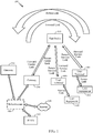
- FIG. 1 illustrates an example of a satellite communication system 100 which includes a plurality of satellites (although only one satellite 300 is shown for clarity of illustration) in non-geosynchronous orbits (NGSO), for example, low-earth orbits (LEO), a gateway 200 in communication with the satellite 300, a plurality of user terminals (UTs) 400 and 401 in communication with the satellite 300, and a plurality of user equipment (UE) 500 and 501 in communication with the UTs 400 and 401, respectively.
- NGSO non-geosynchronous orbits
- LEO low-earth orbits
- UTs user terminals
- UE user equipment
- Each UE 500 or 501 may be a user device such as a mobile device, a telephone, a smartphone, a tablet, a laptop computer, a computer, a wearable device, a smart watch, an audiovisual device, or any device including the capability to communicate with a UT. Additionally, the UE 500 and/or UE 501 may be a device (e.g., access point, small cell, etc.) that is used to communicate with one or more end user devices. In the example illustrated in FIG. 1 , the UT 400 and the UE 500 communicate with each other via a bidirectional access link (having a forward access link and return access link), and similarly, the UT 401 and the UE 501 communicate with each other via another bidirectional access link.
- a bidirectional access link having a forward access link and return access link
- one or more additional UEs may be configured to receive only and therefore communicate with a UT only using a forward access link.
- one or more additional UEs may also communicate with UT 400 or UT 401.
- a UT and a corresponding UE may be integral parts of a single physical device, such as a mobile telephone with an integral satellite transceiver and an antenna for communicating directly with a satellite, for example.
- the gateway 200 may have access to the Internet 108 or one or more other types of public, semiprivate, or private networks.
- the gateway 200 is in communication with infrastructure 106, which is capable of accessing the Internet 108 or one or more other types of public, semiprivate, or private networks.
- the gateway 200 may also be coupled to various types of communication backhaul, including, for example, landline networks such as optical fiber networks or public switched telephone networks (PSTN) 110.
- PSTN public switched telephone networks
- the gateway 200 may interface to the Internet 108, the PSTN 110, or one or more other types of public, semiprivate, or private networks without using the infrastructure 106.
- the gateway 200 may communicate with other gateways, such as gateway 201 through the infrastructure 106 or alternatively may be configured to communicate with the gateway 201 without using the infrastructure 106.
- the infrastructure 106 may include, in whole or part, a network control center (NCC), a satellite control center (SCC), a wired and/or wireless core network, and/or any other components or systems used to facilitate operation of and/or communication with the satellite communication system 100.
- a signal path from the satellite 300 to a ground station which may be the gateway 200 or one of the UTs 400 and 401, may be generically called a downlink.
- a signal path from a ground station to the satellite 300 may be generically called an uplink.
- signals can have a general directionality such as a forward link and a return link or reverse link.
- a communication link in a direction originating from the gateway 200 and terminating at the UT 400 through the satellite 300 is called a forward link
- a communication link in a direction originating from the UT 400 and terminating at the gateway 200 through the satellite 300 is called a return link or reverse link
- the signal path from the gateway 200 to the satellite 300 is labeled "Forward Feeder Link”
- the signal path from the satellite 300 to the gateway 200 is labeled "Return Feeder Link” in FIG. 1
- the signal path from each UT 400 or 401 to the satellite 300 is labeled "Return Service Link”
- the signal path from the satellite 300 to each UT 400 or 401 is labeled "Forward Service Link” in FIG. 1 .
- FIG. 2 is an example block diagram of the gateway 200, which also can apply to the gateway 201 of FIG. 1 .
- the gateway 200 is shown to include a number of antennas 205, an RF subsystem 210, a digital subsystem 220, a Public Switched Telephone Network (PSTN) interface 230, a Local Area Network (LAN) interface 240, a gateway interface 245, and a gateway controller 250.
- the RF subsystem 210 is coupled to the antennas 205 and to the digital subsystem 220.
- the digital subsystem 220 is coupled to the PSTN interface 230, the LAN interface 240, and the gateway interface 245.
- the gateway controller 250 is coupled to the RF subsystem 210, the digital subsystem 220, the PSTN interface 230, the LAN interface 240, and the gateway interface 245.
- the RF subsystem 210 may include a number of RF transceivers 212, an RF controller 214, and an antenna controller 216, may transmit communication signals to a satellite (e.g., satellite 300 of FIG. 1 ) via a forward feeder link 301F, and may receive communication signals from the satellite 300 via a return feeder link 301R.
- a satellite e.g., satellite 300 of FIG. 1
- each of the RF transceivers 212 may include a transmit chain and a receive chain.
- Each receive chain may include a low noise amplifier (LNA) and a down-converter (e.g., a mixer) to amplify and down-convert, respectively, received communication signals in a well-known manner.
- LNA low noise amplifier
- a down-converter e.g., a mixer
- each receive chain may include an analog-to-digital converter (ADC) to convert the received communication signals from analog signals to digital signals (e.g., for processing by the digital subsystem 220).
- ADC analog-to-digital converter
- Each transmit chain may include an up-converter (e.g., a mixer) and a power amplifier (PA) to up-convert and amplify, respectively, communication signals to be transmitted to the satellite 300 in a well-known manner.
- each transmit chain may include a digital-to-analog converter (DAC) to convert the digital signals received from the digital subsystem 220 to analog signals to be transmitted to the satellite 300.
- DAC digital-to-analog converter
- the RF controller 214 may be used to control various aspects of the number of the RF transceivers 212 (e.g., selection of carrier frequency, frequency and phase calibration, gain settings, and the like).
- the antenna controller 216 may control various aspects of the antennas 205 (e.g., beamforming, beam steering, gain settings, frequency tuning, and the like).
- the digital subsystem 220 may include a number of digital receiver modules 222, a number of digital transmitter modules 224, a baseband (BB) processor 226, and a control (CTRL) processor 228.
- the digital subsystem 220 may process communication signals received from the RF subsystem 210 and forward the processed communication signals to the PSTN interface 230 and/or the LAN interface 240, and may process communication signals received from the PSTN interface 230 and/or the LAN interface 240 and forward the processed communication signals to the RF subsystem 210.
- Each digital receiver module 222 may correspond to signal processing elements used to manage communications between a gateway and UT (e.g., gateway 200 and UT 400 of FIG. 1 ).
- One of the receive chains of the RF transceivers 212 may provide input signals to multiple digital receiver modules 222.
- a number of the digital receiver modules 222 may be used to accommodate all of the satellite beams and possible diversity mode signals being handled at any given time.
- each digital receiver module 222 may include one or more digital data receivers, a searcher receiver, and a diversity combiner and decoder circuit.
- the searcher receiver may be used to search for appropriate diversity modes of carrier signals, and may be used to search for pilot signals (or other relatively fixed pattern strong signals).
- the digital transmitter modules 224 may process signals to be transmitted to the UT 400 via the satellite 300.
- each digital transmitter module 224 may include a transmit modulator that modulates data for transmission.
- the transmission power of each transmit modulator may be controlled by a corresponding digital transmit power controller (not shown for simplicity) that may (1) apply a minimum level of power for purposes of interference reduction and resource allocation and (2) apply appropriate levels of power when needed to compensate for attenuation in the transmission path and other path transfer characteristics.
- the CTRL (control) processor 228, which is coupled to the digital receiver module 222, the digital transmitter module 224, and the BB (baseband) processor 226, may provide command and control signals to effect functions such as, but not limited to, signal processing, timing signal generation, power control, handoff control, diversity combining, and system interfacing.
- the CTRL processor 228 may also control the generation and power of pilot, synchronization, and paging channel signals and their coupling to the transmit power controller (not shown for simplicity).
- the pilot channel is a signal that is not modulated by data, and may use a repetitive unchanging pattern or non-varying frame structure type (pattern) or tone type input.
- the orthogonal function used to form the channel for the pilot signal generally has a constant value, such as all 1's or 0's, or a well-known repetitive pattern, such as a structured pattern of interspersed 1's and 0's.
- the BB processor 226 is well known in the art and is therefore not described in detail herein.
- the BB processor 226 may include a variety of known elements such as (but not limited to) coders, data modems, and digital data switching and storage components.
- the PSTN interface 230 may provide communication signals to, and receive communication signals from, an external PSTN either directly or through the infrastructure 106, as illustrated in FIG. 1 .
- the PSTN interface 230 is well known in the art, and therefore is not described in detail herein.
- the PSTN interface 230 may be omitted, or may be replaced with any other suitable interface that connects the gateway 200 to a ground-based network (e.g., the Internet 108 of FIG. 1 ).
- the LAN interface 240 may provide communication signals to, and receive communication signals from, an external LAN.
- the LAN interface 240 may be coupled to the Internet 108 either directly or through the infrastructure 106, as illustrated in FIG. 1 .
- the LAN interface 240 is well known in the art, and therefore is not described in detail herein.
- the gateway interface 245 may provide communication signals to, and receive communication signals from, one or more other gateways associated with the satellite communication system 100 of FIG. 1 (and/or to/from gateways associated with other satellite communication systems, not shown for simplicity). For some implementations, the gateway interface 245 may communicate with other gateways via one or more dedicated communication lines or channels (not shown for simplicity). For other implementations, the gateway interface 245 may communicate with other gateways using the PSTN 110 and/or other networks such as the Internet 108 (see FIG. 1 ). For at least one implementation, the gateway interface 245 may communicate with other gateways via the infrastructure 106.
- the gateway controller 250 may provide overall gateway control.
- the gateway controller 250 may plan and control utilization of the satellite 300's resources by the gateway 200.
- the gateway controller 250 may analyze trends, generate traffic plans, allocate satellite resources, monitor (or track) satellite positions, and monitor the performance of the gateway 200 and/or the satellite 300.
- the gateway controller 250 may also be coupled to a ground-based satellite controller (not shown for simplicity) that maintains and monitors orbits of the satellite 300, relays satellite usage information to the gateway 200, tracks the positions of the satellite 300, and/or adjusts various channel settings of the satellite 300.
- the gateway controller 250 includes local time, frequency, and position references 251, which may provide local time and frequency information to the RF subsystem 210, the digital subsystem 220, and/or the interfaces 230, 240, and 245.
- the time and frequency information may be used to synchronize the various components of the gateway 200 with each other and/or with the satellite 300.
- the local time, frequency, and position references 251 may also provide position information (e.g., ephemeris data) of the satellite 300 to the various components of the gateway 200. Further, although depicted in FIG.
- the local time, frequency, and position references 251 may be a separate subsystem that is coupled to the gateway controller 250 (and/or to one or more of the digital subsystem 220 and the RF subsystem 210).
- the gateway controller 250 may also be coupled to a network control center (NCC) and/or a satellite control center (SCC).
- NCC network control center
- SCC satellite control center
- the gateway controller 250 may allow the SCC to communicate directly with the satellite 300, for example, to retrieve ephemeris data from the satellite 300.
- the gateway controller 250 may also receive processed information (e.g., from the SCC and/or the NCC) that allows the gateway controller 250 to properly aim the antennas 205 (e.g., at the satellite 300), to schedule beam transmissions, to coordinate handovers, and to perform various other well-known functions.
- FIG. 3 is an example block diagram of the satellite 300 for illustrative purposes only. It will be appreciated that specific satellite configurations can vary significantly and may or may not include on-board processing. Further, although illustrated as a single satellite, two or more satellites using inter-satellite communication may provide the functional connection between the gateway 200 and the UT 400. It will be appreciated that the disclosure is not limited to any specific satellite configuration and any satellite or combinations of satellites that can provide the functional connection between the gateway 200 and the UT 400 can be considered within the scope of the disclosure.
- the satellite 300 is shown to include a forward transponder 310, a return transponder 320, an oscillator 330, a controller 340, forward link antennas 351 and 352(1)-352(N), and return link antennas 361(1)-361(N) and 362.
- the forward transponder 310 which may process communication signals within a corresponding channel or frequency band, may include a respective one of first bandpass filters 311(1)-311(N), a respective one of first LNAs 312(1)-312(N), a respective one of frequency converters 313(1)-313(N), a respective one of second LNAs 314(1)-314(N), a respective one of second bandpass filters 315(1)-315(N), and a respective one of PAs 316(1)-316(N).
- Each of the PAs 316(1)-316(N) is coupled to a respective one of antennas 352(1)-352(N), as shown in FIG. 3 .
- the first bandpass filters 311(1)-311(N) Within each of the respective forward paths FP(1)-FP(N), the first bandpass filters 311(1)-311(N), pass signal components having frequencies within the channel or frequency band of the respective forward paths FP(1)-FP(N), and filters signal components having frequencies outside the channel or frequency band of the respective forward paths FP(1)-FP(N).
- the pass band of the first bandpass filters 311(1)-311(N) correspond to the width of the channel associated with the respective forward paths FP(1)-FP(N).
- the first LNAs 312(1)-312(N) amplify the received communication signals to a level suitable for processing by the frequency converters 313(1)-313(N).
- the frequency converters 313(1)-313(N) convert the frequency of the communication signals in the respective forward paths FP(1)-FP(N) (e.g., to a frequency suitable for transmission from the satellite 300 to the UT 400).
- the second LNAs 314(1)-314(N) amplify the frequency-converted communication signals, and the second bandpass filters 315(1)-315(N) filter signal components having frequencies outside of the associated channel width.
- the PAs 316(1)-316(N) amplify the filtered signals to a power level suitable for transmission to the UT 400 via respective antennas 352(1)-352(N).
- the return transponder 320 which includes a number N of return paths RP(1)-RP(N), receives communication signals from the UT 400 along a return service link 302R via antennas 361(1)-361(N), and transmits communication signals to the gateway 200 along the return feeder link 301R via the return link antenna 362.
- Each of the return paths RP(1)-RP(N), which may process communication signals within a corresponding channel or frequency band, may be coupled to a respective one of the antennas 361(1)-361(N), and may include a respective one of first bandpass filters 321(1)-321(N), a respective one of first LNAs 322(1)-322(N), a respective one of frequency converters 323(1)-323(N), a respective one of second LNAs 324(1)-324(N), and a respective one of second bandpass filters 325(1)-325(N).
- the first bandpass filters 321(1)-321(N) pass signal components having frequencies within the channel or frequency band of the respective return paths RP(1)-RP(N), and filters signal components having frequencies outside the channel or frequency band of the respective return paths RP(1)-RP(N).
- the pass band of the first bandpass filters 321(1)-321(N) may for some implementations correspond to the width of the channel associated with the respective return paths RP(1)-RP(N).
- the first LNAs 322(1)-322(N) amplify all the received communication signals to a level suitable for processing by the frequency converters 323(1)-323(N).
- the frequency converters 323(1)-323(N) convert the frequency of the communication signals in the respective return paths RP(1)-RP(N) (e.g., to a frequency suitable for transmission from the satellite 300 to the gateway 200).
- the second LNAs 324(1)-324(N) amplify the frequency-converted communication signals, and the second bandpass filters 325(1)-325(N) filter signal components having frequencies outside of the associated channel width.
- Signals from the return paths RP(1)-RP(N) are combined and provided to the return link antenna 362 via a PA 326.
- the PA 326 amplifies the combined signals for transmission to the gateway 200.
- the oscillator 330 which may be any suitable circuit or device that generates an oscillating signal, provides a forward local oscillator LO(F) signal to the frequency converters 313(1)-313(N) of the forward transponder 310, and provides a return local oscillator LO(R) signal to the frequency converters 323(1)-323(N) of the return transponder 320.
- the LO(F) signal may be used by the frequency converters 313(1)-313(N) to convert communication signals from a frequency band associated with the transmission of signals from the gateway 200 to the satellite 300 to a frequency band associated with the transmission of signals from the satellite 300 to the UT 400.
- the LO(R) signal may be used by the frequency converters 323(1)-323(N) to convert communication signals from a frequency band associated with the transmission of signals from the UT 400 to the satellite 300 to a frequency band associated with the transmission of signals from the satellite 300 to the gateway 200.
- the controller 340 which is coupled to the forward transponder 310, the return transponder 320, and the oscillator 330, may control various operations of the satellite 300 including (but not limited to) channel allocations.
- the controller 340 may include a memory coupled to a processor (not shown for simplicity).
- the memory may include a non-transitory computer-readable medium (e.g., one or more nonvolatile memory elements, such as EPROM, EEPROM, Flash memory, a hard drive, etc.) storing instructions that, when executed by the processor, cause the satellite 300 to perform operations including (but not limited to) those described herein.
- FIG. 4 An example of a transceiver for use in the UT 400 or the UT 401 is illustrated in FIG. 4 .
- at least one antenna 410 is provided for receiving forward link communication signals (e.g., from the satellite 300), which are transferred to an analog receiver 414, where they are down-converted, amplified, and digitized.
- a duplexer element 412 is often used to allow the same antenna to serve both transmit and receive functions.
- a UT transceiver may employ separate antennas for operating at different transmit and receive frequencies.
- the digital communication signals output by the analog receiver 414 are transferred to at least one digital data receivers 416A-416N and at least one searcher receiver 418. Additional digital data receivers 416A-416N can be used to obtain desired levels of signal diversity, depending on the acceptable level of transceiver complexity, as would be apparent to one skilled in the relevant art.
- At least one UT control processor 420 is coupled to the digital data receivers 416A-416N and the searcher receiver 418.
- the control processor 420 provides, among other functions, basic signal processing, timing, power and handoff control or coordination, and selection of frequency used for signal carriers. Another basic control function that may be performed by the control processor 420 is the selection or manipulation of functions to be used for processing various signal waveforms.
- Signal processing by the control processor 420 can include a determination of relative signal strength and computation of various related signal parameters. Such computations of signal parameters, such as timing and frequency may include the use of additional or separate dedicated circuitry to provide increased efficiency or speed in measurements or improved allocation of control processing resources.
- the outputs of the digital data receivers 416A-416N are coupled to digital baseband circuitry 422 within the UT 400.
- the digital baseband circuitry 422 comprises processing and presentation elements used to transfer information to and from UE 500 as shown in FIG. 1 , for example.
- the digital baseband circuitry 422 may comprise a diversity combiner and decoder. Some of these elements may also operate under the control of, or in communication with, the control processor 420.
- the digital baseband circuitry 422 When voice or other data is prepared as an output message or communication signal originating with the UT 400, the digital baseband circuitry 422 is used to receive, store, process, and otherwise prepare the desired data for transmission.
- the digital baseband circuitry 422 provides this data to a transmit modulator 426 operating under the control of the control processor 420.
- the output of the transmit modulator 426 is transferred to a digital transmit power controller 428 which provides output power control to an analog transmit power amplifier 430 for final transmission of the output signal from the antenna 410 to a satellite (e.g., satellite 300).
- the UT 400 also includes a memory 432 associated with the control processor 420.
- the memory 432 may include instructions for execution by the control processor 420 as well as data for processing by the control processor 420.
- the UT 400 also includes an optional local time, frequency and/or position references 434 (e.g., a GPS receiver), which may provide local time, frequency and/or position information to the control processor 420 for various applications, including, for example, time and frequency synchronization for the UT 400.
- an optional local time, frequency and/or position references 434 e.g., a GPS receiver
- the control processor 420 may provide local time, frequency and/or position information to the control processor 420 for various applications, including, for example, time and frequency synchronization for the UT 400.
- the digital data receivers 416A-416N and the searcher receiver 418 are configured with signal correlation elements to demodulate and track specific signals.
- the searcher receiver 418 is used to search for pilot signals, or other relatively fixed pattern strong signals, while the digital data receivers 416A-416N are used to demodulate other signals associated with detected pilot signals.
- the digital data receivers 416A-416N can be assigned to track the pilot signal after acquisition to accurately determine the ratio of signal chip energies to signal noise, and to formulate pilot signal strength. Therefore, the outputs of these digital data receivers 416A-416N can be monitored to determine the energy in, or frequency of, the pilot signal or other signals.
- These digital data receivers 416A-416N also employ frequency tracking elements that can be monitored to provide current frequency and timing information to the control processor 420 for signals being demodulated.
- the control processor 420 may use such information to determine to what extent the received signals are offset from the oscillator frequency, when scaled to the same frequency band, as appropriate. This, and other information related to frequency errors and frequency shifts, can be stored in the memory 432 as desired.
- the control processor 420 may also be coupled to UE interface circuitry 450 to allow communications between the UT 400 and one or more UEs.
- the UE interface circuitry 450 may be configured as desired for communication with various UE configurations and accordingly may include various transceivers and related components depending on the various communication technologies employed to communicate with the various UEs supported.
- the UE interface circuitry 450 may include one or more antennas, a wide area network (WAN) transceiver, a wireless local area network (WLAN) transceiver, a Local Area Network (LAN) interface, a Public Switched Telephone Network (PSTN) interface and/or other known communication technologies configured to communicate with one or more UEs in communication with the UT 400.
- WAN wide area network
- WLAN wireless local area network
- LAN Local Area Network
- PSTN Public Switched Telephone Network
- FIG. 5 is a block diagram illustrating the UE 500, which also can be applied to the UE 501 of FIG. 1 .
- the UE 500 as shown in FIG. 5 may be a mobile device, a handheld computer, a tablet, a wearable device, a smart watch, or any type of device capable of interacting with a user, for example. Additionally, the UE 500 may be a network side device that provides connectivity to various ultimate end user devices and/or to various public or private networks.
- the UE 500 may comprise a LAN interface 502, one or more antennas 504, a wide area network (WAN) transceiver 506, a wireless local area network (WLAN) transceiver 508, and a satellite positioning system (SPS) receiver 510.
- WAN wide area network
- WLAN wireless local area network
- SPS satellite positioning system
- the SPS receiver 510 may be compatible with Global Positioning System (GPS), Global Navigation Satellite System (GLONASS) and/or any other global or regional satellite based positioning system.
- the UE 500 may include the WLAN transceiver 508, such as a Wi-Fi transceiver, with or without the LAN interface 502, the WAN transceiver 506, and/or the SPS receiver 510, for example.
- the UE 500 may include additional transceivers such as Bluetooth, ZigBee and other known technologies, with or without the LAN interface 502, the WAN transceiver 506, the WLAN transceiver 508 and/or the SPS receiver 510. Accordingly, the elements illustrated for the UE 500 are provided merely as an example configuration and are not intended to limit the configuration of UEs in accordance with the various aspects disclosed herein.
- a processor 512 is connected to the LAN interface 502, the WAN transceiver 506, the WLAN transceiver 508, and the SPS receiver 510.
- a motion sensor 514 and/or other sensors may also be coupled to the processor 512.
- a memory 516 is connected to the processor 512.
- the memory 516 may include data 518 that may be transmitted to and/or received from the UT 400, as shown in FIG. 1 .
- the memory 516 may also include stored instructions 520 to be executed by the processor 512 to perform the process steps for communicating with the UT 400.
- the UE 500 may also include a user interface 522, which may include hardware and software for interfacing inputs or outputs of the processor 512 with the UE 500 through light, sound or tactile inputs or outputs, for example.
- the UE 500 includes a microphone/speaker 524, a keypad 526, and a display 528 connected to the user interface 522.
- the user's tactile input or output may be integrated with the display 528 by using a touch-screen display, for example.
- the elements illustrated in FIG. 5 are not intended to limit the configuration of the UEs disclosed herein and it will be appreciated that the elements included in the UE 500 will vary based on the end use of the device and the design choices of the system engineers.
- the UE 500 may be a user device such as a mobile device or external network side device in communication with, but separate from, the UT 400 as illustrated in FIG. 1 , for example.
- the UE 500 and the UT 400 may be integral parts of a single physical device.
- FIG. 6A shows a diagram 600 depicting a GSO satellite 610 and two NGSO satellites 620(1)-620(2) in orbit around the Earth 630.
- the GSO satellite 610 appears motionless in a fixed position in the sky located (e.g., above the Earth's equator 631).
- the GSO satellite 610 maintains a relatively fixed line-of-sight with a corresponding GSO ground station 612.
- This arc of GSO satellite positions may be referred to herein as a GSO arc 640.
- the receiving direction for a GSO ground station (e.g., such as GSO ground station 612) may be defined by an antenna pattern of typically fixed orientation and fixed beam width (such as a beam width defined by an ITU specification).
- the NGSO satellites 620(1)-620(2) are deployed in non-geostationary orbits and revolve around the Earth 630 along various paths above the Earth's surface at relatively low altitudes (e.g., as compared with GSO satellites). Because the NGSO satellites 620(1)-620(2) revolve around the Earth 630 relatively quickly (e.g., approximately every 90 minutes for low-earth-orbit (LEO) satellites), their positions change quickly relative to a fixed location on Earth 630.
- LEO low-earth-orbit
- a plurality of NGSO satellites are typically deployed to form an NGSO satellite constellation, with each of the NGSO satellites providing coverage for a corresponding path across the Earth's surface.
- the NGSO satellite 620(2) is depicted as directing beam 621(1) towards a first coverage area 622(1) on the Earth's surface
- the NGSO satellite 620(1) is depicted as directing beam 621(2) towards a second coverage area 622(2) on the Earth's surface.
- the NGSO satellites 620(1)-620(2) may each transmit any number of beams, and one or more of the beams may be directed towards overlapping regions on the Earth's surface.
- the footprint of a satellite is the surface area (on Earth) within which all UTs can communicate with the satellite (above a minimum elevation angle).
- the area covered by a beam transmitted (e.g., from a corresponding antenna) by the satellite is referred to herein as the beam coverage area.
- the footprint of a satellite may be defined by a number of beam coverage areas provided by a number of beams transmitted from the satellite.
- the NGSO satellites 620(1)-620(2) may communicate with ground-based gateways (not shown in FIG. 6A for simplicity) and UTs using at least part of the same frequency spectrum used by GSO satellite 610.
- the NGSO satellites 620(1)-620(2) should not exceed the EPFD limits established by the ITU.
- a given NGSO satellite beam likely risks exceeding the EPFD limits and potentially interfering with GSO satellite communications if the given NGSO satellite and the GSO satellite 610 are substantially in the same direction when viewed from some point on the Earth's surface within the coverage area of the NGSO satellite beam, so that the NGSO satellite beam is transmitting substantially in the direction of the receiving antenna of a GSO ground station at that location, for example, as defined by the GSO ground station's beam pattern (e.g., antenna pattern).
- the GSO ground station's beam pattern e.g., antenna pattern
- the interference, at any point on the Earth's surface visible from the geostationary orbit, produced by emissions from all the space stations of a non-geostationary-satellite system must not exceed the limits described in the ITU Radio Regulations Article 22. Exceeding these limits could interfere with the operation of geostationary-satellite (GSO) Earth stations. NGSO satellites must reduce power or cease transmitting over areas of the Earth's surface where these limits would be exceeded.
- GSO geostationary-satellite
- FIG. 6B illustrates terminology associated with a footprint of an NGSO satellite 650.
- the footprint 652 of the NGSO satellite 650 forms a circle on the surface of the Earth defined by an Earth-central angle (shown in FIG. 6B as ⁇ ) dictated by the minimum elevation angle (shown in FIG. 6B as ⁇ ) of the Earth station 654 serving the NGSO satellite 650.
- Each NSGO satellite 650 provides coverage to its respective footprint 652 through the beams it transmits to the surface of the Earth from antennas mounted on the NSGO satellite 650.
- a downlink antenna beam pattern is designed as a series of long, narrow beams.
- the beams are oriented so that the contour of each beam on the ground (e.g. the 3 dB down contour) has its long axis (major axis) oriented east to west, and its short axis (minor axis) oriented north to south.
- the beams are aligned so that they are adjacent to each other in the north to south direction.
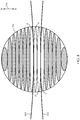
- FIG. 7 illustrates an implementation of an NGSO satellite beam pattern comprising 16 beams, where the beams are numerically labeled 1 through 16, with each beam substantially elliptical in shape and of approximately equal area.
- the beams are arranged to approximately cover an NGSO satellite footprint 702.
- the arrow 704 denotes the northern direction relative to the illustration.
- the minor axes of the ellipses are coincident along a single line, labeled 706, which runs north to south.
- the major axes of the ellipses run east to west.
- the overlap of any two adjacent beam patterns, if there is an overlap is at most a relatively small fraction of the beam pattern area.
- the choice of 16 beams is made for ease of illustration and is not meant to be limiting, so that other implementations may have more or less than 16 beams.
- the east to west orientation of the major axes of the satellite beams may be maintained by yaw steering of the satellites, or otherwise rotating the antenna so as to rotate the beam pattern during each orbit.
- the GSO exclusion zone forms a curved region on the Earth's surface and crosses the NGSO satellite footprint 702 in the east to west direction, but is narrow in the north to south direction.
- FIG. 8 illustrates a GSO exclusion zone for the beam pattern illustrated in FIG. 7 , where the lines 802 and 804 in FIG. 8 bound the GSO exclusion zone.
- the GSO exclusion zone covers beams 9 and 10, and partly covers beams 8 and 11. Consequently, at most beams 8, 9, 10, and 11 would need to be attenuated or turned off, depending upon which beams exceed the EPFD limit.
- the value of the EPFD depends upon the angle of arrival above the horizontal plane as seen by an Earth station, and therefore it may vary from beam to beam.
- the GSO exclusion zone may cover different beams than the ones shown in FIG. 8 .
- the beams cover the NGSO satellite footprint 702 efficiently in the sense that relatively few beams will need to be attenuated or turned off, and a relatively small region of the NGSO satellite footprint 702 outside of the GSO exclusion zone is covered by beams which will need to be attenuated or turned off.
- the region covered by active beams outside of the GSO exclusion zone is a relatively large fraction of the NGSO satellite footprint 702.
- the gain of the long, narrow beams is typically strongest in the center of their coverage area and gradually weakens towards the ends of the major (long) axis. Consequently, as the distance between orbit planes for NGSO satellites decreases toward higher latitudes, and the beams of NGSO satellites in adjacent orbit planes increasingly overlap, it is the weaker portion of the beams that overlap, minimizing interference, and leaving the stronger central area of the beam as the primary region of coverage.
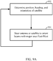
- An NGSO satellite may perform the methods (or processes) illustrated in FIGS. 9A and 9B .
- a determination is made of the position, heading, and orientation of the NGSO satellite. This determination may rely upon GPS measured coordinates and other sensors that provide orientation information, that is, the direction and orientation of a downlink antenna.
- an antenna or the NGSO satellite is steered to orient the beams so that their major axes lie in the east to west direction.
- FIG. 9A illustrates a loop from the action 904 to the action 902 to indicate that this process is a running process so that the beams have the orientation as described with respect to FIG. 7 and FIG. 8 as the NGSO satellite moves in its orbit.
- FIG. 9B illustrates a method for attenuating or turning off a subset of beams in a set of beams for a satellite so that the total power due to the satellite constellation on any point of interest on the surface of the Earth does not exceed the EPFD limit.
- corresponding to the subset of beams is a set of corresponding power levels where each beam in the subset of beams is set at or below its corresponding power level.
- the set of corresponding power levels is such that if any beam in the subset of beams exceeds its corresponding power level, then the EPFD limit will be exceeded for some point of interest on the Earth's surface.
- FIG. 9B provides one such example.
- the beams are indexed by the index i and written as "beam(i)", where the index i runs from 0 to n-1, and where n is an integer denoting the number of beams in the set of beams. If in the action 906 it is determined that the beam(i) would not cause the total power at some point on the Earth's surface to exceed the EPFD limit, then control is brought to the action 907, where the beam(i) is maintained at its current level.
- the power level of beam(i) may be increased if doing so would not cause the EPFD limit to be exceeded. (Of course, a beam cannot be powered beyond its safe limit.) If, however, in the action 906 it is determined that the beam(i) would cause the total power at some point on the Earth's surface to exceed the EPFD limit, then control is brought to the action 908 where that particular beam is turned off or its power is attenuated. Control is then brought to the action 910.
- the index i is incremented by 1 but wraps back to 0 when it has reached n-1. Control is then brought back to the action 906 to indicate that the process illustrated in FIG. 9B is a running process.
- the process in FIG. 9B may be implemented repeatedly, so that each beam is tested to see if it should be attenuated or increased in power. Note that a beam may be attenuated to the point where it is completely powered off.
- the actions of increasing and decreasing (attenuating) a beam power level as indicated in the actions 907 and 908 are performed using some step size, where the step size is an engineering design choice and can depend upon the available technology. Accordingly, the indication that the EPFD limit is exceeded if any beam in the subset of beams exceeds its corresponding power level may be interpreted to mean that the EPFD limit is exceeded when any beam in the subset of beams is a step size above its corresponding power level.
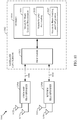
- FIG. 10 is a block diagram of an example satellite 1000 that includes a satellite controller 1002 for performing methods (processes) in accordance with example implementations, including those discussed with respect to FIGS. 9A and 9B .
- the satellite controller 1002 is coupled to a forward transponder 1004 via a first link 1006 and is coupled to a return transponder 1008 via a second link 1010.
- a forward transponder 1004 via a first link 1006
- a return transponder 1008 via a second link 1010.
- FIG. 10 For ease of illustration, not all elements in a typical satellite are shown in FIG. 10 .
- the satellite controller 1002 includes a processor 1012 and a memory 1014.
- the processor 1012 may include multiple processor cores integrated in one or more chips, and consequently reference to the processor 1012 is meant to include one or more processors.
- the memory 1014 may include a non-transitory computer-readable storage medium (e.g., one or more nonvolatile memory elements, such as EPROM, EEPROM, Flash memory, a hard drive, and so on) that may store the following software modules (SW): a beam location determination software module 1016 to facilitate the determination of the current location and altitude of the satellite 1000; a GSO arc locating software module 1018 to facilitate the determination of the location of the GSO arc relative to the satellite 1000; and a beam enabling and configuration software module 1020 to facilitate the enabling or disabling, or the powering up or down, of one or more beams of the satellite 1000, such as to adjust a number of parameters (e.g., antenna configurations, beam steering, antenna gain, and transmit power levels) of one or
- An antenna coupled to the forward transponder 1004 is illustrated as an array of antenna elements, where for ease of illustration only two are shown, labeled 1022 and 1024.
- an antenna coupled to the return transponder 1008 is illustrated as an array of antenna elements, where for ease of illustration only two are shown, labeled 1026 and 1028.
- the implementations discussed herein and in FIGS. 9A and 9B have been directed to the antenna coupled to the forward transponder 1004.
- the antenna elements 1022 and 1024 may represent an electronically steerable antenna, a slotted array antenna, as well as other kinds of antennas with different kinds of polarization, such as for example right-handed polarization or left-handed polarization.
- FIG. 10 may be implemented using any suitable means. Such means also may be implemented, at least in part, using corresponding structures as taught herein.
- the components described above in conjunction with the "module for" components of FIG. 10 also may correspond to similarly designated “means for” functionality.
- one or more such means may be implemented using one or more processor components, integrated circuits, or other suitable structure as taught herein.
- beams may be other than elliptical in shape
- beam patterns may be other than circular in shape.
- a square or rectangular shaped beam pattern with rectangular, oblong, or elliptically shaped beams is desirable.
- likely realizations for satellite systems are a rectangular shaped beam pattern with rectangular shaped beams for polar satellite orbits and a circular shaped beam pattern with elliptically shaped beams for Walker or inclined satellite orbits.
- the amount of overlap between beams in the beam pattern may vary, and the short (minor) axes of the beams may not be coincident along a single line.
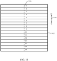
- FIG. 11 provides a particular example of a square beam pattern with 16 beams covering a footprint 1102, but where the beams have a rectangular shape.
- a minor axis for an ellipse may now be referred to as a median (or midline or mid-segment) for a rectangle, although the term minor axis may still be used. More precisely, it is the smaller of the two medians of a rectangular beam that is collinear (coaxial) from one rectangular beam to another. The smaller of the two medians may be referred to as a short median.
- a dashed line 1106 in FIG. 11 represents all the short medians of the rectangular beams lined up with each other.
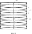
- FIG. 12 provides another particular example of a square beam pattern with 16 beams covering a footprint 1202, but where the beams have an elliptical or oval shape. Such a beam shape is more easily realized than the rectangular shape shown in FIG. 11 , which may be considered to represent an ideal shape.
- a dashed line 1206 in FIG. 12 represents all the short medians of the oval beams lined up with each other.
- a beam may have one of several different shapes, but in practice each beam may be described as relatively short or narrow in the north to south direction, and wide or long in the east to west direction, where the beams are substantially adjacent (contiguous) to each other when viewed looking down into the surface of the footprint. That is, their short medians are collinear, oriented in the north to south direction, it being understood that the short median of an ellipse is its minor axis.
- a beam is narrow along a first median (or first direction) and wide along a second median (or second direction)
- the linear dimension of the beam along the first median (or first direction) is less than the linear dimension of the beam along the second median (or second direction).
- the set of beams making up a beam pattern can be oriented with at most finite precision
- the medians of a set of beams in a beam pattern as substantially collinear or substantially oriented in a particular direction
- the median of each beam in the set of beams can at most be collinear or oriented in a particular direction to within the tolerances available for the particular technology employed in an embodiment.
- a beam may be described as substantially elliptical, it being understood that the shape of the beam will not exactly meet the geometric definition of an ellipse, but that the shape will be recognized by one of ordinary skill in the art as being sufficiently elliptical so that it may be modeled as an ellipse when calculating power or a communication link budget.
- FIG. 13 illustrates an example gateway apparatus 1300 represented as a series of interrelated functional modules as discussed with respect to the examples of FIGS. 9A , 9B , and 10 .
- a module for forming a beam pattern 1304 with the antenna 1302 may correspond at least in some aspects to, for example, a satellite controller or a component thereof as discussed herein (e.g., the satellite controller 1002 of FIG. 10 or the like).
- the module for forming a beam pattern 1304 forms a beam pattern such that for a set of beams in a footprint, each beam is narrow along its first median and wide along its second median, where the first medians are substantially collinear with each other and the second medians are substantially oriented east to west.
- a module for reducing (or attenuating) power to a subset of the set of beams 1306 may correspond at least in some aspects to, for example, a satellite controller or a component thereof as discussed herein (e.g., the satellite controller 1002 of FIG. 10 or the like).
- Each beam in the subset is reduced at or below a corresponding power level such that when a beam is powered above its corresponding power level an equivalent power flux-density (EPFD) exceeds a limit at some point on the Earth's surface.
- EPFD equivalent power flux-density
- the functionality of the modules of FIG. 13 may be implemented in various ways consistent with the teachings herein.
- the functionality of these modules may be implemented as one or more electrical components.
- the functionality of these blocks may be implemented as a processing system including one or more processor components.
- the functionality of these modules may be implemented using, for example, at least a portion of one or more integrated circuits (e.g., an ASIC).
- an integrated circuit may include a processor, software, other related components, or some combination thereof.
- the functionality of different modules may be implemented, for example, as different subsets of an integrated circuit, as different subsets of a set of software modules, or a combination thereof.
- a given subset e.g., of an integrated circuit and/or of a set of software modules
- FIG. 13 may be implemented using any suitable means. Such means also may be implemented, at least in part, using corresponding structure as taught herein.
- the components described above in conjunction with the "module for" components of FIG. 13 also may correspond to similarly designated “means for” functionality.
- one or more of such means may be implemented using one or more of processor components, integrated circuits, or other suitable structure as taught herein.
- a beam may be referred to as substantially elliptical, substantially rectangular, or such that the short medians are substantially collinear.
- substantially is a term of art reflecting the fact that antenna patterns cannot be made to fit a precise geometric definition due to the finite size of the antenna aperture and the tolerances available in the mechanical structures and in the electronic and microwave components.
- a software module may reside in RAM memory, flash memory, ROM memory, EPROM memory, EEPROM memory, registers, hard disk, a removable disk, a CD-ROM, or any other form of storage medium known in the art.
- An exemplary storage medium is coupled to the processor such that the processor can read information from, and write information to, the storage medium. In the alternative, the storage medium may be integral to the processor.
- aspects of the claimed subject matter may include a computer-readable media embodying a method for avoiding exceeding interference limits for a non-geostationary satellite system. Accordingly, the claimed subject matter is not limited to illustrated examples.
Landscapes
- Engineering & Computer Science (AREA)
- Computer Networks & Wireless Communication (AREA)
- Signal Processing (AREA)
- Physics & Mathematics (AREA)
- Astronomy & Astrophysics (AREA)
- General Physics & Mathematics (AREA)
- Aviation & Aerospace Engineering (AREA)
- Radio Relay Systems (AREA)
- Mobile Radio Communication Systems (AREA)
- Remote Sensing (AREA)
Claims (15)
- Ein Verfahren, das Folgendes aufweist:Bilden eines Beam- bzw. Strahlmusters, das einen Satz von Strahlen (1-16) einer Antenne eines Satelliten in einem Fußabdruck des Satelliten (702) aufweist, wobei jeder Strahl einen ersten Median und einen zweiten Median hat, wobei jeder Strahl entlang seines ersten Median schmal ist und entlang seines zweiten Median breit ist, wobei die ersten Mediane im Wesentlichen kollinearer zueinander sind und die zweiten Mediane im Wesentlichen von Osten nach Westen ausgerichtet sind; undVerringern von Leistung an einen Subsatz des Satzes von Strahlen (8, 9, 10, 11), wobei jeder Strahl in dem Subsatz auf einen oder unter einen entsprechenden Leistungspegel verringert wird, so dass, wenn ein Strahl mit Leistung über seinem entsprechenden Leistungspegel versorgt wird, eine äquivalente Leistungsflussdichte eine spezifizierte Grenze an einem gewissen Punkt auf der Erdoberfläche überschreiten wird.
- Verfahren nach Anspruch 1, wobei die spezifizierte Grenze durch die International Telecommunication Union spezifiziert wird um das Verursachen einer nicht akzeptablen Interferenz gegenüber Netzwerken geostationärer Satelliten zu verhindern.
- Verfahren nach Anspruch 1, wobei die Antenne eine elektronisch steuerbare Antenne ist.
- Verfahren nach Anspruch 1, wobei der Schritt des Bildens des Satzes von Strahlen Giersteuerung des Satelliten oder Drehen der Antenne aufweist.
- Verfahren nach Anspruch 1, wobei jeder Strahl im Wesentlichen die gleiche Fläche hat.
- Verfahren nach Anspruch 1, wobei jeder Strahl im Wesentlichen eine elliptische Form hat, wobei der erste Median von jedem Strahl ihre Nebenachse ist und der zweite Median jedes Strahls ihre Hauptachse ist, oder im Wesentlichen eine rechteckige Form hat.
- Verfahren nach Anspruch 1, wobei der Schritt des Verringerns von Leistung an den Subsatz Abschalten jedes Strahls in dem Subsatz aufweist.
- Ein Satellit (1000), der Folgendes aufweist:eine Antenne (1022, 1024);Mittel (1004) zum Bilden eines Beam- bzw. Strahlmusters mit der Antenne, wobei das Strahlmuster einen Satz von Strahlen einer Antenne eines Satelliten in einem Fußabdruck des Satelliten (702) aufweist, wobei jeder Strahl einen ersten Median und einen zweiten Median hat, wobei jeder Strahl entlang seines ersten Median schmal ist und entlang seines zweiten Median breit ist, wobei die ersten Mediane im Wesentlichen kollinearer zueinander sind und die zweiten Mediane im Wesentlichen von Osten nach Westen ausgerichtet sind; undMittel zum Verringern von Leistung (1002) an einen Subsatz des Satzes von Strahlen (8, 9, 10, 11), wobei jeder Strahl in dem Subsatz auf einen oder unter einen entsprechenden Leistungspegel verringert wird, so dass, wenn ein Strahl mit Leistung über seinem entsprechenden Leistungspegel versorgt wird, eine äquivalente Leistungsflussdichte eine spezifizierte Grenze an einem gewissen Punkt auf der Erdoberfläche überschreiten wird.
- Satellit nach Anspruch 8, wobei die spezifizierte Grenze durch die International Telecommunication Union spezifiziert wird um das Verursachen einer nicht akzeptablen Interferenz gegenüber Netzwerken geostationärer Satelliten zu verhindern.
- Satellit nach Anspruch 8, wobei die Mittel zum Bilden des Strahlmusters konfiguriert sind zum elektronischen Steuern der Antenne zum Bilden des Satzes von Strahlen.
- Satellit nach Anspruch 8, wobei die Mittel zum Bilden des Strahlmusters konfiguriert sind zur Giersteuerung des Satelliten oder zum Drehen der Antenne zum Bilden des Satzes von Strahlen.
- Satellit nach Anspruch 8, wobei jeder Strahl im Wesentlichen die gleiche Fläche hat.
- Satellit nach Anspruch 8, wobei jeder Strahl im Wesentlichen eine elliptische Form hat, wobei der erste Median von jedem Strahl ihre Nebenachse ist und der zweite Median von jedem Strahl ihre Hauptachse ist, oder im Wesentlichen eine rechteckige Form hat.
- Satellit nach Anspruch 8, wobei die Mittel zum Verringerns von Leistung an den Subsatz konfiguriert sind, jeden Strahl in dem Subsatz abzuschalten.
- Ein nicht transitorisches computerlesbares Medium mit gespeicherten Instruktionen, die, wenn sie durch einen Prozessor ausgeführt werden, wobei der Prozessor an Bord eines Satelliten (1000) ist, der eine Antenne (1022, 1024) hat, den Prozessor veranlassen zum Durchführen eines Verfahrens gemäß einem der Ansprüche 1 bis 7.
Applications Claiming Priority (3)
| Application Number | Priority Date | Filing Date | Title |
|---|---|---|---|
| US201562142769P | 2015-04-03 | 2015-04-03 | |
| US14/865,390 US11146328B2 (en) | 2015-04-03 | 2015-09-25 | Method and apparatus for avoiding exceeding interference limits for a non-geostationary satellite system |
| PCT/US2016/023922 WO2016160487A1 (en) | 2015-04-03 | 2016-03-24 | Method and apparatus for avoiding exceeding interference limits for a non-geostationary satellite system |
Publications (2)
| Publication Number | Publication Date |
|---|---|
| EP3278472A1 EP3278472A1 (de) | 2018-02-07 |
| EP3278472B1 true EP3278472B1 (de) | 2018-10-17 |
Family
ID=55650778
Family Applications (1)
| Application Number | Title | Priority Date | Filing Date |
|---|---|---|---|
| EP16714188.6A Active EP3278472B1 (de) | 2015-04-03 | 2016-03-24 | Verfahren und vorrichtung zur vermeidung der überschreitung von interferenzgrenzen für ein nicht-geostationäres satellitensystem |
Country Status (7)
| Country | Link |
|---|---|
| US (1) | US11146328B2 (de) |
| EP (1) | EP3278472B1 (de) |
| JP (1) | JP6731941B2 (de) |
| CN (1) | CN107408979B (de) |
| ES (1) | ES2705749T3 (de) |
| HU (1) | HUE042848T2 (de) |
| WO (1) | WO2016160487A1 (de) |
Families Citing this family (35)
| Publication number | Priority date | Publication date | Assignee | Title |
|---|---|---|---|---|
| US10149200B2 (en) * | 2016-06-07 | 2018-12-04 | Iridium Satellite Llc | Interference mitigation for a satellite network |
| EP3664316B1 (de) * | 2016-10-21 | 2023-07-19 | Viasat, Inc. | Bodenbasierte strahlgeformte kommunikationen unter verwendung von gemeinsam synchronisierten, räumlich multiplexten feeder-verbindungen |
| US10582456B2 (en) * | 2017-06-07 | 2020-03-03 | Ethertronics, Inc. | Power control method for systems with altitude changing objects |
| CN108712202B (zh) * | 2018-05-16 | 2019-05-21 | 清华大学 | 通过偏转天线指向规避同频干扰的方法及卫星通信系统 |
| US10756860B2 (en) | 2018-11-05 | 2020-08-25 | XCOM Labs, Inc. | Distributed multiple-input multiple-output downlink configuration |
| US10812216B2 (en) | 2018-11-05 | 2020-10-20 | XCOM Labs, Inc. | Cooperative multiple-input multiple-output downlink scheduling |
| US10659112B1 (en) | 2018-11-05 | 2020-05-19 | XCOM Labs, Inc. | User equipment assisted multiple-input multiple-output downlink configuration |
| US10432272B1 (en) | 2018-11-05 | 2019-10-01 | XCOM Labs, Inc. | Variable multiple-input multiple-output downlink user equipment |
| CN116667909A (zh) * | 2018-11-21 | 2023-08-29 | 松下航空电子公司 | 用于使用固态功率放大器进行功率共享的方法和系统 |
| WO2020112840A1 (en) | 2018-11-27 | 2020-06-04 | XCOM Labs, Inc. | Non-coherent cooperative multiple-input multiple-output communications |
| US11063645B2 (en) | 2018-12-18 | 2021-07-13 | XCOM Labs, Inc. | Methods of wirelessly communicating with a group of devices |
| US10756795B2 (en) | 2018-12-18 | 2020-08-25 | XCOM Labs, Inc. | User equipment with cellular link and peer-to-peer link |
| US11330649B2 (en) | 2019-01-25 | 2022-05-10 | XCOM Labs, Inc. | Methods and systems of multi-link peer-to-peer communications |
| US10756767B1 (en) | 2019-02-05 | 2020-08-25 | XCOM Labs, Inc. | User equipment for wirelessly communicating cellular signal with another user equipment |
| US10735057B1 (en) | 2019-04-29 | 2020-08-04 | XCOM Labs, Inc. | Uplink user equipment selection |
| US10686502B1 (en) | 2019-04-29 | 2020-06-16 | XCOM Labs, Inc. | Downlink user equipment selection |
| US11411778B2 (en) | 2019-07-12 | 2022-08-09 | XCOM Labs, Inc. | Time-division duplex multiple input multiple output calibration |
| CN110417460B (zh) * | 2019-08-16 | 2021-03-30 | 国家无线电监测中心 | 一种非静止轨道卫星对静止轨道卫星干扰的分析方法 |
| US11533104B2 (en) * | 2020-01-28 | 2022-12-20 | Samsung Electronics Co., Ltd | System and method for providing beam planning for interference-aware satellite beam pattern design |
| US11411779B2 (en) | 2020-03-31 | 2022-08-09 | XCOM Labs, Inc. | Reference signal channel estimation |
| US12526830B2 (en) | 2020-04-03 | 2026-01-13 | Myriota Pty Ltd | System and method for adaptive communications |
| KR20230008750A (ko) | 2020-04-15 | 2023-01-16 | 엑스콤 랩스 인코퍼레이티드 | 무선 네트워크 멀티포인트 연관 및 다양성 |
| CN112054838B (zh) * | 2020-09-11 | 2022-05-17 | 中国科学院微小卫星创新研究院 | 一种ngso卫星偏置方案的设计方法 |
| CN114449437B (zh) * | 2020-10-20 | 2023-05-09 | 大唐移动通信设备有限公司 | 一种干扰处理方法、装置、设备及可读存储介质 |
| WO2022241436A1 (en) | 2021-05-14 | 2022-11-17 | XCOM Labs, Inc. | Scrambling identifiers for wireless communication systems |
| CN113595616B (zh) * | 2021-07-27 | 2022-05-17 | 北京邮电大学 | 一种基于卫星天线波束指向优化的ngso系统间干扰减缓方法 |
| US11569904B1 (en) | 2021-08-02 | 2023-01-31 | Hubble Network Inc. | Differentiating orthogonally modulated signals received from multiple transmitters at one or more antenna arrays |
| US11283516B1 (en) * | 2021-08-02 | 2022-03-22 | Hubble Network Inc | Multi spoke beamforming for low power wide area satellite and terrestrial networks |
| CN114039646B (zh) * | 2021-10-26 | 2024-11-22 | 中国电子科技集团公司第五十四研究所 | 一种支持干扰规避的ngso卫星系统信令波束设计方法 |
| EP4300845B1 (de) * | 2022-06-29 | 2025-11-12 | Deutsche Telekom AG | Verfahren zur übertragung von dienstzeitinformationen an ein benutzergerät in einem mobilkommunikationsnetz oder mit einem nicht terrestrischen netzwerk, basisstation, system und computerlesbares medium |
| EP4300844B1 (de) * | 2022-06-29 | 2025-11-12 | Deutsche Telekom AG | Verfahren zum ermöglichen der kommunikation zwischen einem benutzergerät und einem mobilen kommunikationsnetz, das ein nicht-terrestrisches netz ist oder aufweist, basisstation, system und computerlesbares medium |
| US20240014891A1 (en) * | 2022-07-06 | 2024-01-11 | Mediatek Inc. | Beam management in non-terrestrial networks |
| CN116192236A (zh) * | 2023-02-15 | 2023-05-30 | 中国人民解放军61096部队 | 多波束卫星资源腾退方法、装置、电子设备及介质 |
| WO2025007335A1 (en) * | 2023-07-06 | 2025-01-09 | Qualcomm Incorporated | Interference mitigation based on satellite location |
| US20250116784A1 (en) * | 2023-10-06 | 2025-04-10 | Kymeta Corporation | Assured position, navigation, and timing gnss denied solution for a satellite terminal |
Family Cites Families (28)
| Publication number | Priority date | Publication date | Assignee | Title |
|---|---|---|---|---|
| JPS5812441A (ja) * | 1981-07-15 | 1983-01-24 | Mitsubishi Electric Corp | 人工衛星の送信電力制御方式 |
| JPS61133733A (ja) | 1984-12-03 | 1986-06-21 | Nippon Telegr & Teleph Corp <Ntt> | 人工衛星のアンテナ指向制御方法 |
| US4965605A (en) | 1989-05-16 | 1990-10-23 | Hac | Lightweight, low profile phased array antenna with electromagnetically coupled integrated subarrays |
| FR2677197B1 (fr) | 1991-05-31 | 1994-09-16 | Alcatel Espace | Systeme de communications par satellites en orbite basse a destination de terminaux mobiles. |
| US5227802A (en) * | 1991-12-23 | 1993-07-13 | Motorola, Inc. | Satellite system cell management |
| FR2695775B1 (fr) * | 1992-09-11 | 1994-11-10 | France Telecom | Procédé de reconfiguration de couvertures de faisceau d'antenne dans un réseau par satellite. |
| US6236834B1 (en) * | 1993-12-15 | 2001-05-22 | International Mobile Satellite Organization | Method and apparatus for limiting interference between satellite systems |
| JP2639359B2 (ja) * | 1994-10-31 | 1997-08-13 | 日本電気株式会社 | 非静止衛星用送信装置 |
| US5621415A (en) * | 1994-11-15 | 1997-04-15 | Teledesic Corporation | Linear cell satellite system |
| IT1275349B (it) | 1994-11-25 | 1997-08-05 | Alenia Spazio Spa | Antenna con fascio ellittico ruotabile con possibilita' di riconfigurazione e zoom del fascio |
| US5541607A (en) * | 1994-12-05 | 1996-07-30 | Hughes Electronics | Polar digital beamforming method and system |
| JPH10150397A (ja) | 1996-11-20 | 1998-06-02 | Nec Corp | 送信電力制御方法及び送信電力制御システム |
| EP0951760A1 (de) | 1997-01-17 | 1999-10-27 | Edward F. Tuck | Verfahren zur steuerung eines energiestrahls in einem zellularen satellitenübertragungssystem |
| US6055431A (en) * | 1997-12-19 | 2000-04-25 | The Aerospace Corporation | Adaptive control of multiple beam communication transponders |
| US5977907A (en) | 1998-02-02 | 1999-11-02 | Motorola, Inc. | Method and system for antenna pattern synthesis based on geographical distribution of subscribers |
| US6272345B1 (en) | 1998-07-31 | 2001-08-07 | Motorola, Inc. | Method and apparatus for region based hand-offs in a satellite communication system |
| FR2786641B1 (fr) | 1998-11-26 | 2002-01-25 | Cit Alcatel | Procede de telecommunication dans lequel des terminaux emettent vers une meme station |
| US6678520B1 (en) | 1999-01-07 | 2004-01-13 | Hughes Electronics Corporation | Method and apparatus for providing wideband services using medium and low earth orbit satellites |
| US6511020B2 (en) | 2000-01-07 | 2003-01-28 | The Boeing Company | Method for limiting interference between satellite communications systems |
| US8116253B2 (en) * | 2002-10-08 | 2012-02-14 | Qualcomm Incorporated | Controlling forward and reverse link traffic channel power |
| ES2684443T3 (es) | 2007-10-09 | 2018-10-02 | Viasat, Inc. | Uso sin interferencias de banda de frecuencia de satélite no geoestacionario para la comunicación vía satélite geoestacionario |
| CN102316058B (zh) | 2011-03-18 | 2014-04-09 | 中国科学院上海微系统与信息技术研究所 | 非静止轨道卫星dqpsk通信的相干解调装置 |
| FR2976749B1 (fr) | 2011-06-16 | 2013-06-28 | Astrium Sas | Dispositif et procede d'optimisation de la couverture au sol d'un systeme spatial hybride. |
| KR20130104337A (ko) | 2012-03-13 | 2013-09-25 | 한국전자통신연구원 | 다중 빔 위성 통신 시스템에서의 자원 할당 장치 및 방법 |
| US9123988B2 (en) | 2012-11-29 | 2015-09-01 | Viasat, Inc. | Device and method for reducing interference with adjacent satellites using a mechanically gimbaled asymmetrical-aperture antenna |
| CN103684632B (zh) | 2013-11-28 | 2016-05-25 | 北京科技大学 | 一种深空航天器到地球的Ka波段信道建模方法 |
| US9538538B2 (en) * | 2015-03-20 | 2017-01-03 | Qualcomm Incorporated | Satellite beam power backoff |
| US9730227B2 (en) * | 2015-03-20 | 2017-08-08 | Qualcomm Incorporated | Dynamic frequency allocation of satellite beams |
-
2015
- 2015-09-25 US US14/865,390 patent/US11146328B2/en active Active
-
2016
- 2016-03-24 EP EP16714188.6A patent/EP3278472B1/de active Active
- 2016-03-24 HU HUE16714188A patent/HUE042848T2/hu unknown
- 2016-03-24 WO PCT/US2016/023922 patent/WO2016160487A1/en not_active Ceased
- 2016-03-24 JP JP2017550859A patent/JP6731941B2/ja active Active
- 2016-03-24 CN CN201680019582.5A patent/CN107408979B/zh active Active
- 2016-03-24 ES ES16714188T patent/ES2705749T3/es active Active
Also Published As
| Publication number | Publication date |
|---|---|
| WO2016160487A1 (en) | 2016-10-06 |
| US11146328B2 (en) | 2021-10-12 |
| ES2705749T3 (es) | 2019-03-26 |
| CN107408979B (zh) | 2020-08-07 |
| US20170019814A1 (en) | 2017-01-19 |
| JP2018515962A (ja) | 2018-06-14 |
| CN107408979A (zh) | 2017-11-28 |
| EP3278472A1 (de) | 2018-02-07 |
| JP6731941B2 (ja) | 2020-07-29 |
| HUE042848T2 (hu) | 2019-07-29 |
Similar Documents
| Publication | Publication Date | Title |
|---|---|---|
| EP3278472B1 (de) | Verfahren und vorrichtung zur vermeidung der überschreitung von interferenzgrenzen für ein nicht-geostationäres satellitensystem | |
| EP3272031B1 (de) | Dynamische frequenzzuweisung von satellitenstrahlen | |
| EP3353906B1 (de) | Erfassung von leo-satelliten ohne kompass | |
| US10425865B2 (en) | Channel quality feedback in satellite communication systems | |
| US10553943B2 (en) | Low-cost satellite user terminal antenna | |
| EP3272032B1 (de) | Verfahren und vorrichtung für zeit- oder frequenzsynchronisation in nicht-geosynchronen satellitenkommunikationssystemen | |
| US9525477B1 (en) | Frequency tracking with sparse pilots | |
| HK1242484A1 (en) | Method and apparatus for avoiding exceeding interference limits for a non-geostationary satellite system | |
| HK1242484B (zh) | 用於避免超过非地球静止卫星系统的干扰限制的方法和装置 | |
| HK1242855A1 (en) | Improving epfd coverage for ngso satellites | |
| HK1242855B (zh) | 改进ngso卫星epfd覆盖的方法和装置 |
Legal Events
| Date | Code | Title | Description |
|---|---|---|---|
| STAA | Information on the status of an ep patent application or granted ep patent |
Free format text: STATUS: THE INTERNATIONAL PUBLICATION HAS BEEN MADE |
|
| PUAI | Public reference made under article 153(3) epc to a published international application that has entered the european phase |
Free format text: ORIGINAL CODE: 0009012 |
|
| STAA | Information on the status of an ep patent application or granted ep patent |
Free format text: STATUS: REQUEST FOR EXAMINATION WAS MADE |
|
| 17P | Request for examination filed |
Effective date: 20171031 |
|
| AK | Designated contracting states |
Kind code of ref document: A1 Designated state(s): AL AT BE BG CH CY CZ DE DK EE ES FI FR GB GR HR HU IE IS IT LI LT LU LV MC MK MT NL NO PL PT RO RS SE SI SK SM TR |
|
| AX | Request for extension of the european patent |
Extension state: BA ME |
|
| GRAP | Despatch of communication of intention to grant a patent |
Free format text: ORIGINAL CODE: EPIDOSNIGR1 |
|
| STAA | Information on the status of an ep patent application or granted ep patent |
Free format text: STATUS: GRANT OF PATENT IS INTENDED |
|
| RIC1 | Information provided on ipc code assigned before grant |
Ipc: H01Q 1/28 20060101ALI20180404BHEP Ipc: H04B 7/185 20060101AFI20180404BHEP Ipc: H04B 7/204 20060101ALI20180404BHEP Ipc: H01Q 1/36 20060101ALI20180404BHEP Ipc: H01Q 3/34 20060101ALI20180404BHEP Ipc: H01Q 3/28 20060101ALI20180404BHEP |
|
| INTG | Intention to grant announced |
Effective date: 20180424 |
|
| DAV | Request for validation of the european patent (deleted) | ||
| DAX | Request for extension of the european patent (deleted) | ||
| GRAS | Grant fee paid |
Free format text: ORIGINAL CODE: EPIDOSNIGR3 |
|
| GRAA | (expected) grant |
Free format text: ORIGINAL CODE: 0009210 |
|
| STAA | Information on the status of an ep patent application or granted ep patent |
Free format text: STATUS: THE PATENT HAS BEEN GRANTED |
|
| AK | Designated contracting states |
Kind code of ref document: B1 Designated state(s): AL AT BE BG CH CY CZ DE DK EE ES FI FR GB GR HR HU IE IS IT LI LT LU LV MC MK MT NL NO PL PT RO RS SE SI SK SM TR |
|
| REG | Reference to a national code |
Ref country code: GB Ref legal event code: FG4D |
|
| REG | Reference to a national code |
Ref country code: CH Ref legal event code: EP |
|
| REG | Reference to a national code |
Ref country code: IE Ref legal event code: FG4D |
|
| REG | Reference to a national code |
Ref country code: DE Ref legal event code: R096 Ref document number: 602016006556 Country of ref document: DE Ref country code: AT Ref legal event code: REF Ref document number: 1055232 Country of ref document: AT Kind code of ref document: T Effective date: 20181115 |
|
| REG | Reference to a national code |
Ref country code: NL Ref legal event code: FP |
|
| REG | Reference to a national code |
Ref country code: CH Ref legal event code: NV Representative=s name: MAUCHER JENKINS PATENTANWAELTE AND RECHTSANWAE, DE |
|
| REG | Reference to a national code |
Ref country code: LT Ref legal event code: MG4D |
|
| REG | Reference to a national code |
Ref country code: AT Ref legal event code: MK05 Ref document number: 1055232 Country of ref document: AT Kind code of ref document: T Effective date: 20181017 |
|
| REG | Reference to a national code |
Ref country code: ES Ref legal event code: FG2A Ref document number: 2705749 Country of ref document: ES Kind code of ref document: T3 Effective date: 20190326 |
|
| PG25 | Lapsed in a contracting state [announced via postgrant information from national office to epo] |
Ref country code: NO Free format text: LAPSE BECAUSE OF FAILURE TO SUBMIT A TRANSLATION OF THE DESCRIPTION OR TO PAY THE FEE WITHIN THE PRESCRIBED TIME-LIMIT Effective date: 20190117 Ref country code: PL Free format text: LAPSE BECAUSE OF FAILURE TO SUBMIT A TRANSLATION OF THE DESCRIPTION OR TO PAY THE FEE WITHIN THE PRESCRIBED TIME-LIMIT Effective date: 20181017 Ref country code: LT Free format text: LAPSE BECAUSE OF FAILURE TO SUBMIT A TRANSLATION OF THE DESCRIPTION OR TO PAY THE FEE WITHIN THE PRESCRIBED TIME-LIMIT Effective date: 20181017 Ref country code: BG Free format text: LAPSE BECAUSE OF FAILURE TO SUBMIT A TRANSLATION OF THE DESCRIPTION OR TO PAY THE FEE WITHIN THE PRESCRIBED TIME-LIMIT Effective date: 20190117 Ref country code: LV Free format text: LAPSE BECAUSE OF FAILURE TO SUBMIT A TRANSLATION OF THE DESCRIPTION OR TO PAY THE FEE WITHIN THE PRESCRIBED TIME-LIMIT Effective date: 20181017 Ref country code: HR Free format text: LAPSE BECAUSE OF FAILURE TO SUBMIT A TRANSLATION OF THE DESCRIPTION OR TO PAY THE FEE WITHIN THE PRESCRIBED TIME-LIMIT Effective date: 20181017 Ref country code: IS Free format text: LAPSE BECAUSE OF FAILURE TO SUBMIT A TRANSLATION OF THE DESCRIPTION OR TO PAY THE FEE WITHIN THE PRESCRIBED TIME-LIMIT Effective date: 20190217 Ref country code: AT Free format text: LAPSE BECAUSE OF FAILURE TO SUBMIT A TRANSLATION OF THE DESCRIPTION OR TO PAY THE FEE WITHIN THE PRESCRIBED TIME-LIMIT Effective date: 20181017 |
|
| PG25 | Lapsed in a contracting state [announced via postgrant information from national office to epo] |
Ref country code: GR Free format text: LAPSE BECAUSE OF FAILURE TO SUBMIT A TRANSLATION OF THE DESCRIPTION OR TO PAY THE FEE WITHIN THE PRESCRIBED TIME-LIMIT Effective date: 20190118 Ref country code: PT Free format text: LAPSE BECAUSE OF FAILURE TO SUBMIT A TRANSLATION OF THE DESCRIPTION OR TO PAY THE FEE WITHIN THE PRESCRIBED TIME-LIMIT Effective date: 20190217 Ref country code: RS Free format text: LAPSE BECAUSE OF FAILURE TO SUBMIT A TRANSLATION OF THE DESCRIPTION OR TO PAY THE FEE WITHIN THE PRESCRIBED TIME-LIMIT Effective date: 20181017 Ref country code: AL Free format text: LAPSE BECAUSE OF FAILURE TO SUBMIT A TRANSLATION OF THE DESCRIPTION OR TO PAY THE FEE WITHIN THE PRESCRIBED TIME-LIMIT Effective date: 20181017 Ref country code: SE Free format text: LAPSE BECAUSE OF FAILURE TO SUBMIT A TRANSLATION OF THE DESCRIPTION OR TO PAY THE FEE WITHIN THE PRESCRIBED TIME-LIMIT Effective date: 20181017 |
|
| REG | Reference to a national code |
Ref country code: DE Ref legal event code: R097 Ref document number: 602016006556 Country of ref document: DE |
|
| REG | Reference to a national code |
Ref country code: HU Ref legal event code: AG4A Ref document number: E042848 Country of ref document: HU |
|
| PG25 | Lapsed in a contracting state [announced via postgrant information from national office to epo] |
Ref country code: IT Free format text: LAPSE BECAUSE OF FAILURE TO SUBMIT A TRANSLATION OF THE DESCRIPTION OR TO PAY THE FEE WITHIN THE PRESCRIBED TIME-LIMIT Effective date: 20181017 Ref country code: DK Free format text: LAPSE BECAUSE OF FAILURE TO SUBMIT A TRANSLATION OF THE DESCRIPTION OR TO PAY THE FEE WITHIN THE PRESCRIBED TIME-LIMIT Effective date: 20181017 Ref country code: CZ Free format text: LAPSE BECAUSE OF FAILURE TO SUBMIT A TRANSLATION OF THE DESCRIPTION OR TO PAY THE FEE WITHIN THE PRESCRIBED TIME-LIMIT Effective date: 20181017 |
|
| PLBE | No opposition filed within time limit |
Free format text: ORIGINAL CODE: 0009261 |
|
| STAA | Information on the status of an ep patent application or granted ep patent |
Free format text: STATUS: NO OPPOSITION FILED WITHIN TIME LIMIT |
|
| PG25 | Lapsed in a contracting state [announced via postgrant information from national office to epo] |
Ref country code: SK Free format text: LAPSE BECAUSE OF FAILURE TO SUBMIT A TRANSLATION OF THE DESCRIPTION OR TO PAY THE FEE WITHIN THE PRESCRIBED TIME-LIMIT Effective date: 20181017 Ref country code: RO Free format text: LAPSE BECAUSE OF FAILURE TO SUBMIT A TRANSLATION OF THE DESCRIPTION OR TO PAY THE FEE WITHIN THE PRESCRIBED TIME-LIMIT Effective date: 20181017 Ref country code: EE Free format text: LAPSE BECAUSE OF FAILURE TO SUBMIT A TRANSLATION OF THE DESCRIPTION OR TO PAY THE FEE WITHIN THE PRESCRIBED TIME-LIMIT Effective date: 20181017 Ref country code: SM Free format text: LAPSE BECAUSE OF FAILURE TO SUBMIT A TRANSLATION OF THE DESCRIPTION OR TO PAY THE FEE WITHIN THE PRESCRIBED TIME-LIMIT Effective date: 20181017 |
|
| 26N | No opposition filed |
Effective date: 20190718 |
|
| PG25 | Lapsed in a contracting state [announced via postgrant information from national office to epo] |
Ref country code: MC Free format text: LAPSE BECAUSE OF FAILURE TO SUBMIT A TRANSLATION OF THE DESCRIPTION OR TO PAY THE FEE WITHIN THE PRESCRIBED TIME-LIMIT Effective date: 20181017 |
|
| PG25 | Lapsed in a contracting state [announced via postgrant information from national office to epo] |
Ref country code: LU Free format text: LAPSE BECAUSE OF NON-PAYMENT OF DUE FEES Effective date: 20190324 |
|
| REG | Reference to a national code |
Ref country code: BE Ref legal event code: MM Effective date: 20190331 |
|
| PG25 | Lapsed in a contracting state [announced via postgrant information from national office to epo] |
Ref country code: IE Free format text: LAPSE BECAUSE OF NON-PAYMENT OF DUE FEES Effective date: 20190324 |
|
| PG25 | Lapsed in a contracting state [announced via postgrant information from national office to epo] |
Ref country code: BE Free format text: LAPSE BECAUSE OF NON-PAYMENT OF DUE FEES Effective date: 20190331 |
|
| PG25 | Lapsed in a contracting state [announced via postgrant information from national office to epo] |
Ref country code: TR Free format text: LAPSE BECAUSE OF FAILURE TO SUBMIT A TRANSLATION OF THE DESCRIPTION OR TO PAY THE FEE WITHIN THE PRESCRIBED TIME-LIMIT Effective date: 20181017 |
|
| PG25 | Lapsed in a contracting state [announced via postgrant information from national office to epo] |
Ref country code: MT Free format text: LAPSE BECAUSE OF NON-PAYMENT OF DUE FEES Effective date: 20190324 |
|
| PG25 | Lapsed in a contracting state [announced via postgrant information from national office to epo] |
Ref country code: CY Free format text: LAPSE BECAUSE OF FAILURE TO SUBMIT A TRANSLATION OF THE DESCRIPTION OR TO PAY THE FEE WITHIN THE PRESCRIBED TIME-LIMIT Effective date: 20181017 |
|
| PG25 | Lapsed in a contracting state [announced via postgrant information from national office to epo] |
Ref country code: SI Free format text: LAPSE BECAUSE OF FAILURE TO SUBMIT A TRANSLATION OF THE DESCRIPTION OR TO PAY THE FEE WITHIN THE PRESCRIBED TIME-LIMIT Effective date: 20181017 |
|
| PGFP | Annual fee paid to national office [announced via postgrant information from national office to epo] |
Ref country code: HU Payment date: 20220222 Year of fee payment: 7 Ref country code: FI Payment date: 20220224 Year of fee payment: 7 Ref country code: CH Payment date: 20220210 Year of fee payment: 7 |
|
| PG25 | Lapsed in a contracting state [announced via postgrant information from national office to epo] |
Ref country code: MK Free format text: LAPSE BECAUSE OF FAILURE TO SUBMIT A TRANSLATION OF THE DESCRIPTION OR TO PAY THE FEE WITHIN THE PRESCRIBED TIME-LIMIT Effective date: 20181017 |
|
| PG25 | Lapsed in a contracting state [announced via postgrant information from national office to epo] |
Ref country code: FI Free format text: LAPSE BECAUSE OF NON-PAYMENT OF DUE FEES Effective date: 20230324 |
|
| REG | Reference to a national code |
Ref country code: CH Ref legal event code: PL |
|
| PG25 | Lapsed in a contracting state [announced via postgrant information from national office to epo] |
Ref country code: LI Free format text: LAPSE BECAUSE OF NON-PAYMENT OF DUE FEES Effective date: 20230331 Ref country code: HU Free format text: LAPSE BECAUSE OF NON-PAYMENT OF DUE FEES Effective date: 20230325 Ref country code: CH Free format text: LAPSE BECAUSE OF NON-PAYMENT OF DUE FEES Effective date: 20230331 |
|
| PGFP | Annual fee paid to national office [announced via postgrant information from national office to epo] |
Ref country code: ES Payment date: 20250409 Year of fee payment: 10 |
|
| PGFP | Annual fee paid to national office [announced via postgrant information from national office to epo] |
Ref country code: NL Payment date: 20260211 Year of fee payment: 11 |
|
| PGFP | Annual fee paid to national office [announced via postgrant information from national office to epo] |
Ref country code: GB Payment date: 20260211 Year of fee payment: 11 |
|
| PGFP | Annual fee paid to national office [announced via postgrant information from national office to epo] |
Ref country code: DE Payment date: 20260213 Year of fee payment: 11 |
|
| PGFP | Annual fee paid to national office [announced via postgrant information from national office to epo] |
Ref country code: FR Payment date: 20260209 Year of fee payment: 11 |