EP3277932B1 - Ensemble rotor et turbomachine à paliers à gaz comportant un tel ensemble rotor - Google Patents
Ensemble rotor et turbomachine à paliers à gaz comportant un tel ensemble rotor Download PDFInfo
- Publication number
- EP3277932B1 EP3277932B1 EP16719449.7A EP16719449A EP3277932B1 EP 3277932 B1 EP3277932 B1 EP 3277932B1 EP 16719449 A EP16719449 A EP 16719449A EP 3277932 B1 EP3277932 B1 EP 3277932B1
- Authority
- EP
- European Patent Office
- Prior art keywords
- shaft
- rotor assembly
- bearing
- band
- assembly according
- Prior art date
- Legal status (The legal status is an assumption and is not a legal conclusion. Google has not performed a legal analysis and makes no representation as to the accuracy of the status listed.)
- Active
Links
Images
Classifications
-
- F—MECHANICAL ENGINEERING; LIGHTING; HEATING; WEAPONS; BLASTING
- F04—POSITIVE - DISPLACEMENT MACHINES FOR LIQUIDS; PUMPS FOR LIQUIDS OR ELASTIC FLUIDS
- F04D—NON-POSITIVE-DISPLACEMENT PUMPS
- F04D29/00—Details, component parts, or accessories
- F04D29/26—Rotors specially for elastic fluids
- F04D29/266—Rotors specially for elastic fluids mounting compressor rotors on shafts
-
- F—MECHANICAL ENGINEERING; LIGHTING; HEATING; WEAPONS; BLASTING
- F01—MACHINES OR ENGINES IN GENERAL; ENGINE PLANTS IN GENERAL; STEAM ENGINES
- F01D—NON-POSITIVE DISPLACEMENT MACHINES OR ENGINES, e.g. STEAM TURBINES
- F01D15/00—Adaptations of machines or engines for special use; Combinations of engines with devices driven thereby
- F01D15/10—Adaptations for driving, or combinations with, electric generators
-
- F—MECHANICAL ENGINEERING; LIGHTING; HEATING; WEAPONS; BLASTING
- F01—MACHINES OR ENGINES IN GENERAL; ENGINE PLANTS IN GENERAL; STEAM ENGINES
- F01D—NON-POSITIVE DISPLACEMENT MACHINES OR ENGINES, e.g. STEAM TURBINES
- F01D5/00—Blades; Blade-carrying members; Heating, heat-insulating, cooling or antivibration means on the blades or the members
- F01D5/02—Blade-carrying members, e.g. rotors
- F01D5/025—Fixing blade carrying members on shafts
-
- F—MECHANICAL ENGINEERING; LIGHTING; HEATING; WEAPONS; BLASTING
- F02—COMBUSTION ENGINES; HOT-GAS OR COMBUSTION-PRODUCT ENGINE PLANTS
- F02B—INTERNAL-COMBUSTION PISTON ENGINES; COMBUSTION ENGINES IN GENERAL
- F02B37/00—Engines characterised by provision of pumps driven at least for part of the time by exhaust
- F02B37/04—Engines with exhaust drive and other drive of pumps, e.g. with exhaust-driven pump and mechanically-driven second pump
- F02B37/10—Engines with exhaust drive and other drive of pumps, e.g. with exhaust-driven pump and mechanically-driven second pump at least one pump being alternatively or simultaneously driven by exhaust and other drive, e.g. by pressurised fluid from a reservoir or an engine-driven pump
-
- F—MECHANICAL ENGINEERING; LIGHTING; HEATING; WEAPONS; BLASTING
- F02—COMBUSTION ENGINES; HOT-GAS OR COMBUSTION-PRODUCT ENGINE PLANTS
- F02B—INTERNAL-COMBUSTION PISTON ENGINES; COMBUSTION ENGINES IN GENERAL
- F02B39/00—Component parts, details, or accessories relating to, driven charging or scavenging pumps, not provided for in groups F02B33/00 - F02B37/00
- F02B39/02—Drives of pumps; Varying pump drive gear ratio
- F02B39/08—Non-mechanical drives, e.g. fluid drives having variable gear ratio
- F02B39/10—Non-mechanical drives, e.g. fluid drives having variable gear ratio electric
-
- F—MECHANICAL ENGINEERING; LIGHTING; HEATING; WEAPONS; BLASTING
- F04—POSITIVE - DISPLACEMENT MACHINES FOR LIQUIDS; PUMPS FOR LIQUIDS OR ELASTIC FLUIDS
- F04D—NON-POSITIVE-DISPLACEMENT PUMPS
- F04D25/00—Pumping installations or systems
- F04D25/02—Units comprising pumps and their driving means
- F04D25/024—Units comprising pumps and their driving means the driving means being assisted by a power recovery turbine
-
- F—MECHANICAL ENGINEERING; LIGHTING; HEATING; WEAPONS; BLASTING
- F04—POSITIVE - DISPLACEMENT MACHINES FOR LIQUIDS; PUMPS FOR LIQUIDS OR ELASTIC FLUIDS
- F04D—NON-POSITIVE-DISPLACEMENT PUMPS
- F04D25/00—Pumping installations or systems
- F04D25/02—Units comprising pumps and their driving means
- F04D25/06—Units comprising pumps and their driving means the pump being electrically driven
- F04D25/0606—Units comprising pumps and their driving means the pump being electrically driven the electric motor being specially adapted for integration in the pump
-
- F—MECHANICAL ENGINEERING; LIGHTING; HEATING; WEAPONS; BLASTING
- F04—POSITIVE - DISPLACEMENT MACHINES FOR LIQUIDS; PUMPS FOR LIQUIDS OR ELASTIC FLUIDS
- F04D—NON-POSITIVE-DISPLACEMENT PUMPS
- F04D29/00—Details, component parts, or accessories
- F04D29/05—Shafts or bearings, or assemblies thereof, specially adapted for elastic fluid pumps
- F04D29/056—Bearings
- F04D29/057—Bearings hydrostatic; hydrodynamic
-
- H—ELECTRICITY
- H02—GENERATION; CONVERSION OR DISTRIBUTION OF ELECTRIC POWER
- H02K—DYNAMO-ELECTRIC MACHINES
- H02K1/00—Details of the magnetic circuit
- H02K1/06—Details of the magnetic circuit characterised by the shape, form or construction
- H02K1/22—Rotating parts of the magnetic circuit
- H02K1/27—Rotor cores with permanent magnets
-
- H—ELECTRICITY
- H02—GENERATION; CONVERSION OR DISTRIBUTION OF ELECTRIC POWER
- H02K—DYNAMO-ELECTRIC MACHINES
- H02K1/00—Details of the magnetic circuit
- H02K1/06—Details of the magnetic circuit characterised by the shape, form or construction
- H02K1/22—Rotating parts of the magnetic circuit
- H02K1/27—Rotor cores with permanent magnets
- H02K1/2706—Inner rotors
-
- H—ELECTRICITY
- H02—GENERATION; CONVERSION OR DISTRIBUTION OF ELECTRIC POWER
- H02K—DYNAMO-ELECTRIC MACHINES
- H02K1/00—Details of the magnetic circuit
- H02K1/06—Details of the magnetic circuit characterised by the shape, form or construction
- H02K1/22—Rotating parts of the magnetic circuit
- H02K1/27—Rotor cores with permanent magnets
- H02K1/2706—Inner rotors
- H02K1/272—Inner rotors the magnetisation axis of the magnets being perpendicular to the rotor axis
- H02K1/2726—Inner rotors the magnetisation axis of the magnets being perpendicular to the rotor axis the rotor consisting of a single magnet or two or more axially juxtaposed single magnets
-
- H—ELECTRICITY
- H02—GENERATION; CONVERSION OR DISTRIBUTION OF ELECTRIC POWER
- H02K—DYNAMO-ELECTRIC MACHINES
- H02K7/00—Arrangements for handling mechanical energy structurally associated with dynamo-electric machines, e.g. structural association with mechanical driving motors or auxiliary dynamo-electric machines
- H02K7/003—Couplings; Details of shafts
-
- F—MECHANICAL ENGINEERING; LIGHTING; HEATING; WEAPONS; BLASTING
- F01—MACHINES OR ENGINES IN GENERAL; ENGINE PLANTS IN GENERAL; STEAM ENGINES
- F01D—NON-POSITIVE DISPLACEMENT MACHINES OR ENGINES, e.g. STEAM TURBINES
- F01D15/00—Adaptations of machines or engines for special use; Combinations of engines with devices driven thereby
- F01D15/08—Adaptations for driving, or combinations with, pumps
-
- F—MECHANICAL ENGINEERING; LIGHTING; HEATING; WEAPONS; BLASTING
- F04—POSITIVE - DISPLACEMENT MACHINES FOR LIQUIDS; PUMPS FOR LIQUIDS OR ELASTIC FLUIDS
- F04D—NON-POSITIVE-DISPLACEMENT PUMPS
- F04D25/00—Pumping installations or systems
- F04D25/02—Units comprising pumps and their driving means
- F04D25/06—Units comprising pumps and their driving means the pump being electrically driven
-
- F—MECHANICAL ENGINEERING; LIGHTING; HEATING; WEAPONS; BLASTING
- F04—POSITIVE - DISPLACEMENT MACHINES FOR LIQUIDS; PUMPS FOR LIQUIDS OR ELASTIC FLUIDS
- F04D—NON-POSITIVE-DISPLACEMENT PUMPS
- F04D25/00—Pumping installations or systems
- F04D25/02—Units comprising pumps and their driving means
- F04D25/06—Units comprising pumps and their driving means the pump being electrically driven
- F04D25/0606—Units comprising pumps and their driving means the pump being electrically driven the electric motor being specially adapted for integration in the pump
- F04D25/0613—Units comprising pumps and their driving means the pump being electrically driven the electric motor being specially adapted for integration in the pump the electric motor being of the inside-out type, i.e. the rotor is arranged radially outside a central stator
- F04D25/064—Details of the rotor
-
- F—MECHANICAL ENGINEERING; LIGHTING; HEATING; WEAPONS; BLASTING
- F04—POSITIVE - DISPLACEMENT MACHINES FOR LIQUIDS; PUMPS FOR LIQUIDS OR ELASTIC FLUIDS
- F04D—NON-POSITIVE-DISPLACEMENT PUMPS
- F04D29/00—Details, component parts, or accessories
- F04D29/05—Shafts or bearings, or assemblies thereof, specially adapted for elastic fluid pumps
- F04D29/053—Shafts
-
- F—MECHANICAL ENGINEERING; LIGHTING; HEATING; WEAPONS; BLASTING
- F04—POSITIVE - DISPLACEMENT MACHINES FOR LIQUIDS; PUMPS FOR LIQUIDS OR ELASTIC FLUIDS
- F04D—NON-POSITIVE-DISPLACEMENT PUMPS
- F04D29/00—Details, component parts, or accessories
- F04D29/26—Rotors specially for elastic fluids
- F04D29/28—Rotors specially for elastic fluids for centrifugal or helico-centrifugal pumps for radial-flow or helico-centrifugal pumps
- F04D29/284—Rotors specially for elastic fluids for centrifugal or helico-centrifugal pumps for radial-flow or helico-centrifugal pumps for compressors
-
- F—MECHANICAL ENGINEERING; LIGHTING; HEATING; WEAPONS; BLASTING
- F05—INDEXING SCHEMES RELATING TO ENGINES OR PUMPS IN VARIOUS SUBCLASSES OF CLASSES F01-F04
- F05D—INDEXING SCHEME FOR ASPECTS RELATING TO NON-POSITIVE-DISPLACEMENT MACHINES OR ENGINES, GAS-TURBINES OR JET-PROPULSION PLANTS
- F05D2220/00—Application
- F05D2220/40—Application in turbochargers
-
- F—MECHANICAL ENGINEERING; LIGHTING; HEATING; WEAPONS; BLASTING
- F05—INDEXING SCHEMES RELATING TO ENGINES OR PUMPS IN VARIOUS SUBCLASSES OF CLASSES F01-F04
- F05D—INDEXING SCHEME FOR ASPECTS RELATING TO NON-POSITIVE-DISPLACEMENT MACHINES OR ENGINES, GAS-TURBINES OR JET-PROPULSION PLANTS
- F05D2220/00—Application
- F05D2220/70—Application in combination with
- F05D2220/76—Application in combination with an electrical generator
Definitions
- the present invention relates to a rotor assembly and a gas-bearing turbomachine comprising such a rotor assembly.
- a machine is intended to rotate at very high speeds. Thanks to high rotation speeds, it is in fact possible to create at the level of the bearings of the rotor a film of gas (air) which carries the rotor allowing it to rotate without contact with the stator.
- a turbomachine is a device making it possible to recover energy from a fluid and/or to supply energy to a fluid. It is possible, for example, to have an expansion turbine which recovers mechanical energy from a gaseous or liquid flow and which thus drives a mechanical system. This energy can also be used to be communicated to another fluid, for example to compress it.
- a turbomachine can also be driven by a motor, for example an electric motor.
- turbomachines used for supplying compressed air to a fuel cell in a motor vehicle.
- other applications can be envisaged, such as for example a use in an air conditioning system in the aeronautical field or the railway field for example.
- the moving assembly is composed of a set of tubular parts positioned relative to each other and which are held in their position by axial clamping provided by a tie rod passing through at least one part of all the parts.
- the document US2014/0186745 illustrates for example such an arrangement.
- this assembly comprises a turbine wheel and a compressor wheel
- these wheels are generally of larger diameters than that of the bearings supporting the assembly. Dismantling must therefore be considered to insert the moving assembly into its bearings after it has been balanced. It is then necessary to maintain a precise angular and radial positioning during reassembly so as not to induce unbalance. Marking is then carried out on the parts constituting the mobile assembly to reassemble them in the same relative position.
- the document WO-2013/028521 discloses an air supply device for a fuel cell, which comprises a shaft, a compressor wheel which is arranged in a compressor housing and which is fixed to one of the ends of the shaft, a bearing structure which is arranged in a bearing housing for mounting the shaft and an electric motor for driving the shaft, which electric motor is arranged in the bearing housing, the shaft having two shaft bearing portions which are formed by separate components, and having a magnetized portion which is disposed between the shaft bearing parts and forms a separate component and forms the rotor of the electric motor, the shaft bearing parts and the magnetized part being braced relative to each other, and the shaft bearing parts and the magnetized part being centered with respect to each other by means of a centering device which engages an outer edge, the bearing parts d shaft and the magnetic part both in each case axially against each other.
- turbomachines with a one-piece solid shaft whose diameter remains small in order to be able to reach high rotation speeds (see for example the document US4986733 ).
- the ends of the shaft are threaded and each receives an impeller with a corresponding female thread.
- the precise positioning of the impeller is ensured by an intermediate piece between the shaft and the impeller. Thanks to precise machining with tight geometric and dimensional tolerances, it is thus possible not to create any imbalance when mounting each wheel.
- Such turbomachines are not designed to receive a magnet and thus form the rotor of an electric motor. If a magnet is mounted around the solid shaft, the speeds of rotation that can be reached are below the speeds necessary for the air supply of a fuel cell, for example. Furthermore, such a structure can only be envisaged for small shaft end diameters. As soon as the diameter increases, the centrifugal forces and the differential expansion between a wheel made of light alloy and the shaft made of an alloy with high mechanical characteristics do not make it possible to guarantee good relative positioning of the rotating parts.
- the object of the present invention is therefore to provide a turbomachine architecture integrating an electric motor making it possible to achieve good balancing with good repeatability of this balancing.
- a turbomachine will preferably be compact and/or will have good energy efficiency.
- the present invention proposes a rotor assembly for a gas-bearing turbomachine comprising a permanent magnet, a first shaft having at least one bearing intended to cooperate with a support bearing to form a gas bearing and ensure rotational guidance of the first shaft as well as a thrust disc.
- the permanent magnet is a solid magnet tightly mounted inside a hoop made of a non-magnetic material; the hoop forms a one-piece assembly with the first shaft in the extension thereof, and a second shaft having at least one bearing intended to cooperate with a support bearing to form a gas bearing and provide rotational guidance of the second shaft extends from the hoop on the side opposite the first shaft, coaxially with the first shaft such that the first shaft, the hoop and the second shaft form a single unit.
- This new rotor assembly architecture thus provides a one-piece assembly which makes it possible to achieve balancing outside of a turbomachine and not to modify this balancing when the assembly is then mounted in the turbomachine.
- the non-magnetic material for making the hoop and the fact of having a solid magnet allow optimization of the electric motor in which the rotor will take place. It is thus possible to optimize this electric motor, in particular in terms of mass and size.
- a single tubular piece preferably in a non-magnetic material, inside which a permanent magnet would fit and which would thus form the hoop, on a first side of the latter the first tree and on the other side of it the second tree.
- a preferred embodiment provides that the hoop is welded on the one hand to the first shaft and on the other hand to the second shaft.
- first shaft and the second shaft are each a tubular shaft.
- a keying system is advantageously provided between the compressor wheel and the first shaft.
- a turbine wheel In a rotor assembly as described here, provision can also be made for the second shaft to carry, opposite the hoop, a turbine wheel.
- the latter makes it possible, for example, to recover energy from a gas stream and to supply it, for example, to the compressor wheel of the first shaft. It is also possible to provide a keying system between the turbine wheel and the second shaft.
- this turbomachine has for example two gas bearings.
- this turbomachine may have a bidirectional gas thrust bearing placed on either side of a disk made on a shaft of its rotor assembly.
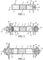
- FIG. 1 shows a one-piece assembly made up of four separate parts that cannot be dismantled. This assembly thus comprises a first shaft 2, a hoop 4, a solid permanent magnet 6 and a second shaft 8.
- the first shaft 2 is a cylindrical tubular shaft with a longitudinal axis 10 made for example of stainless steel. Its outer surface is machined at least at the level of a zone 12 so as to serve as a bearing in a non-contact bearing of the gas bearing type. The machining is of course adapted to the type of bearing produced.
- the diameter of the shaft at the bearing affects the load capacity of the machine in which the rotor will be mounted. In the present invention, by way of illustration and not limitation, it is indicated that the diameter air bearings is for example greater than or equal to 25 mm and is for example in a diameter range of the order of 35 to 50 mm.
- the first shaft 2 has one end welded to the hoop 4.
- the latter also has a cylindrical tubular shape.
- the hoop 4 has a longitudinal axis and the weld between the first shaft 2 and the hoop 4 is made such that the longitudinal axis of the hoop 4 coincides with that of the first shaft 2 to form only one longitudinal axis. 10.
- the hoop 4 grips the magnet 6 so that the two parts are integral with each other.
- the material chosen to make hoop 4 is a non-magnetic material.
- the hoop is for example made of a material marketed under the registered trademark Inconel, that is to say an alloy based on nickel, chromium and iron and also containing small amounts of carbon, silicon and manganese. . Such an alloy has a high resistance to corrosion and interesting mechanical characteristics.
- Magnet 6 is a conventional magnet used as a permanent magnet in an electric motor. It is advantageously of solid cylindrical shape. Its outer surface is of course adapted to the inner surface of hoop 4. The fact of having a solid magnet, without a recess in its center, makes it possible to limit the length (measured longitudinally) of the magnet since the torque of the corresponding motor depends in particular on the volume of this magnet. It is therefore possible to limit the size of the corresponding electric motor.
- the hoop 4 is welded to the second shaft 8.
- the latter is for example also made of stainless steel. It has an overall tubular cylindrical shape, closed at its end opposite the hoop 4.
- the second shaft 8 is also welded to the hoop 4 so that its longitudinal axis coincides with the longitudinal axis 10 of the first shaft 2 and of fret 4.
- the second shaft 8 also has a bearing on its outer surface.
- This bearing is of the same nature as the bearing of the first shaft 2. It is thus a contactless bearing, for example a gas bearing or even a magnetic bearing. It is made in a zone 14 of the second shaft 8.
- a disc 16 protruding radially from the outer surface of the second shaft 8.
- This disc 16 is arranged between the zone 14 forming a bearing and the end of the second shaft 8 opposite the hoop 4.
- This end of the second shaft 8 is closed by a bottom 18 in which is formed a thread 20.
- the bottom 18 is a solid bottom up to the face facing outwards and also has in its face facing outwards the second shaft 8 and in which the thread 20, housings 22 in the form of longitudinal holes.
- the bottom 18 could for example be entirely embedded inside the second shaft 8 and have a centered axial boss projecting outwards in which the thread 20 would be made to allow fixing by screwing of a wheel.
- FIG. 2 illustrates the one-piece assembly of the figure 1 with a compressor wheel 24 mounted at the free end (that is to say opposite the hoop 4) of the first shaft 2 and a turbine wheel 26 mounted at the free end, here also opposite the hoop 4, of the second tree 8.
- the compressor wheel 24 is fixed to a flange 28 which closes the first shaft 2.
- the flange 28 is threaded at its center and has, in the embodiment illustrated, around its central thread an annular groove 30.
- the flange 28 can be mounted in the first shaft 2 in various ways. According to a first variant, it is possible to provide a tight assembly in the first shaft 2 by cooling, for example, the flange 28 with liquid nitrogen and by heating the first shaft 2. After assembly, the two parts are then integral with one of the 'other.
- a second variant provides for example that the flange 28 is threaded over part of its length and that the first shaft 2 is tapped at its end receiving the compressor wheel 24.
- the non-threaded part of the flange 28 is for example mounted with a light tightening in the first shaft 2 (for example by slightly heating the first shaft 2 before assembly) then the flange, once centered, takes up its final position by screwing.
- flange 28 and other mounting methods can be envisaged.
- the compressor wheel 24 is then fixed on the flange 28 using a screw 32 cooperating with the central thread.
- the compressor wheel 24 has a shoulder 34 which is centered on an inner surface of the annular groove 30 when fixing the compressor wheel 24 on the first shaft 2, or more precisely on the flange 28. shoulder end 34 and the corresponding housings made at the bottom of the annular groove 30. It is thus possible to always guarantee the same relative positioning of the compressor wheel 24 with the first shaft 2. It is possible, for example, to provide a regular arrangement housings (and pawns) and add an additional housing (and pawn).
- the turbine wheel 26 is fixed on the bottom 18 of the second shaft 8.
- a screw 36 is provided here to cooperate with the thread 20 of the bottom 18.
- the assembly of the compressor wheel 24 it is possible to provide a keying system between the turbine wheel 26 and the second shaft 8 by providing the turbine wheel 26 with pins and a pattern of corresponding housings accepting only one possibility of assembly (for example several circular pins and a square section pin with corresponding circular housings and a single square housing for the square section pin).
- FIG. 3 illustrates a variant embodiment of the assembly of the figure 2 .
- a turbine wheel 26 on the second shaft 8 and a compressor wheel 24 on the first shaft 2.
- the assembly of the turbine wheel 26, as illustrated in the picture 3 is the same as the assembly shown on the picture 2 and described above.
- the embodiment chosen on the picture 3 provides screwed mounting of the compressor wheel 24 directly in the first shaft 2.
- the compressor wheel 24 has a threaded hub 38 which cooperates with a thread made in the inner wall of the first shaft 2 at its free end .
- the first shaft 2 can be machined from extruded tube. This reduces material consumption, machining time and cost price.
- the compressor wheel is made of a light alloy, in particular based on aluminium, and the shaft of steel, in particular stainless steel, the high temperatures of the parts during operation of the turbomachine in which they are mounted, cause differential expansion.
- the diameter of the compressor wheel increases faster than that of the shaft.
- the shape of the compressor wheel and the shape of the turbine wheel are given by way of non-limiting and merely illustrative examples. Other shapes and other types of mounting for these wheels could be envisaged.
- the position of the disc which serves as an axial stop, the position of each bearing, can of course also vary. However, preferably, provision is made to place the disc on the side of the one-piece assembly opposite to that receiving the compressor wheel.
- a rotor assembly as described above is suitable for rotating at high speeds, even greater than 100,000 rpm.sup. -1 .
- the wheels (or a single wheel) are mounted on the one-piece assembly and the whole is balanced.
- the rotor assembly as described above has fewer parts than comparable prior art assemblies. Compared to the devices of the prior art with a central tie rod for maintaining the stack of parts, it is also noted that it is possible to have a solid magnet, which is then overall less bulky.
- the proposed architecture makes it possible to reduce the number of stacked parts, to reduce geometric and dimensional tolerances, and to obtain a simpler and more reliable shape.
Landscapes
- Engineering & Computer Science (AREA)
- Mechanical Engineering (AREA)
- General Engineering & Computer Science (AREA)
- Power Engineering (AREA)
- Chemical & Material Sciences (AREA)
- Combustion & Propulsion (AREA)
- Physics & Mathematics (AREA)
- Fluid Mechanics (AREA)
- Structures Of Non-Positive Displacement Pumps (AREA)
- Turbine Rotor Nozzle Sealing (AREA)
Description
- La présente invention concerne un ensemble rotor et une turbomachine à paliers à gaz comportant un tel ensemble rotor. Une telle machine est destinée à tourner à de très grandes vitesses. Grâce à des vitesses de rotation élevées, il est en effet possible de créer au niveau des paliers du rotor un film de gaz (air) qui vient porter le rotor lui permettant de tourner sans contact avec le stator.
- Une turbomachine est un dispositif permettant de récupérer de l'énergie d'un fluide et/ou de fournir de l'énergie à un fluide. On peut avoir par exemple une turbine de détente qui récupère de l'énergie mécanique d'un flux gazeux ou liquide et qui ainsi entraine un système mécanique. Cette énergie peut aussi être utilisée pour être communiquée à un autre fluide, par exemple pour le comprimer. Une turbomachine peut aussi être entrainée par un moteur, par exemple un moteur électrique.
- L'invention décrite ci-après a été réalisée dans le domaine des turbomachines utilisées pour l'alimentation en air comprimé d'une pile à combustible dans un véhicule automobile. Cependant, d'autres applications peuvent être envisagées, comme par exemple une utilisation dans un système de conditionnement d'air dans le domaine aéronautique ou le domaine ferroviaire par exemple.
- Dans des applications telles celles évoquées plus haut, il convient d'avoir des vitesses de rotation très élevées pour obtenir des rendements importants et ne pas influencer trop négativement le rendement global de la pile à combustible (ou d'un autre système, par exemple système de conditionnement d'air). Les vitesses de rotation à envisager ici sont d'au moins 100.000 tr.min-1. À de telles vitesses de rotation, il convient d'avoir un excellent positionnement des pièces mobiles les unes par rapport aux autres et de pouvoir garantir que ce positionnement relatif n'évolue pas au cours du temps pour ne pas venir créer un balourd. En outre, il convient de prévoir pour les pièces tournantes des paliers sans contact, par exemple à gaz ou aérodynamiques.
- Dans les turbomachines connues de l'art antérieur, l'ensemble mobile est composé d'un ensemble de pièces tubulaires positionnées les unes par rapport aux autres et qui sont maintenues dans leur position par un serrage axial assuré par un tirant traversant au moins une partie de l'ensemble des pièces. Le document
US2014/0186745 illustre par exemple un tel montage. - Compte tenu des vitesses de rotation de l'ensemble mobile, un équilibrage de cet ensemble doit être réalisé avant la mise en fonction de la turbomachine. Lorsque cet ensemble comporte une roue turbine et une roue compresseur, ces roues sont généralement de diamètres plus grands que celui des paliers supportant l'ensemble. Un démontage doit donc être envisagé pour insérer l'ensemble mobile dans ses paliers après son équilibrage. Il convient de conserver alors un positionnement angulaire et radial précis lors du remontage pour ne pas induire de balourd. Un repérage est alors réalisé sur les pièces constituant l'ensemble mobile pour les remonter dans la même position relative.
- Le document
WO-2013/028521 divulgue un dispositif d'alimentation en air pour une pile à combustible, qui comprend un arbre, une roue de compresseur qui est agencée dans un carter de compresseur et qui est fixée à l'une des extrémités de l'arbre, une structure de palier qui est agencée dans un boîtier de palier servant à monter l'arbre et un moteur électrique servant à entraîner l'arbre, lequel moteur électrique est agencé dans le boîtier de palier, l'arbre possédant deux parties de portée d'arbre qui sont formées par des composants séparés, et possédant une portion aimantée qui est disposée entre les parties de portée d'arbre et forme un composant séparé et forme le rotor du moteur électrique, les parties de portée de l'arbre et la partie aimantée étant entretoisées l'une par rapport à l'autre, et les parties de portée d'arbre et la partie aimantée étant centrées l'une par rapport à l'autre au moyen d'un dispositif de centrage qui attaque un bord extérieur, les parties de portée d'arbre et la partie aimantée portant dans chaque cas axialement l'une contre l'autre. - Un assemblage tel que présenté ci-dessus a pour inconvénient de présenter un nombre de pièces empilées relativement élevé. De ce fait, l'addition des tolérances de fabrication et d'assemblage entraine des difficultés à atteindre des qualités d'équilibrage nécessaires pour fonctionner à hautes vitesses. En effet, de par cette conception, des moments internes sont créés et limitent les vitesses atteignables.
- Il existe également des turbomachines présentant un arbre plein monobloc dont le diamètre reste faible afin de pouvoir atteindre des vitesses de rotation élevées (voir par exemple le document
US4986733 ). Les extrémités de l'arbre sont filetées et reçoivent chacune une roue avec un taraudage correspondant. Le positionnement précis de la roue est assuré par une pièce intermédiaire entre l'arbre et la roue. Grâce à un usinage précis avec des tolérances géométriques et dimensionnelles serrées, il est ainsi possible de ne pas créer de balourd lors du montage de chaque roue. - Le document
WO2014/080087 divulgue également un ensemble rotor pour turbomachine de l'art antérieur. - De telles turbomachines ne sont pas conçues pour recevoir un aimant et former ainsi le rotor d'un moteur électrique. Si un aimant est monté autour de l'arbre plein, les vitesses de rotation pouvant être atteintes sont en-dessous des vitesses nécessaires pour l'alimentation en air d'une pile à combustible par exemple. En outre, une telle structure n'est envisageable que pour des diamètres de bout d'arbre faibles. Dès que le diamètre augmente, les efforts centrifuges et la dilatation différentielle entre une roue réalisée en alliage léger et l'arbre réalisé en alliage à hautes caractéristiques mécaniques ne permettent pas de garantir un bon positionnement relatif des pièces en rotation.
- La présente invention a alors pour but de fournir une architecture de turbomachine intégrant un moteur électrique permettant de réaliser un bon équilibrage avec une bonne répétabilité de cet équilibrage. Une telle turbomachine sera de préférence compacte et/ou présentera un bon rendement énergétique.
- À cet effet, la présente invention propose un ensemble rotor pour turbomachine à paliers à gaz comportant un aimant permanent, un premier arbre présentant au moins un palier destiné à coopérer avec un palier support pour former un palier à gaz et assurer un guidage en rotation du premier arbre ainsi qu'un disque de butée.
- Selon la présente invention, l'aimant permanent est un aimant plein monté serré à l'intérieur d'une frette réalisée dans un matériau amagnétique ; la frette forme un ensemble monobloc avec le premier arbre dans le prolongement de celui-ci, et un second arbre présentant au moins un palier destiné à coopérer avec un palier support pour former un palier à gaz et assurer un guidage en rotation du second arbre s'étend à partir de la frette du côté opposé au premier arbre, de manière coaxiale avec le premier arbre de telle sorte que le premier arbre, la frette et le second arbre forment un ensemble monobloc.
- Cette nouvelle architecture d'ensemble rotor fournit ainsi un ensemble monobloc qui permet de réaliser un équilibrage hors d'une turbomachine et de ne pas modifier cet équilibrage lorsque l'ensemble est ensuite monté dans la turbomachine. Le matériau amagnétique pour réaliser la frette ainsi que le fait d'avoir un aimant plein permettent une optimisation du moteur électrique dans lequel le rotor viendra prendre place. Il est ainsi possible d'optimiser ce moteur électrique notamment en termes de masse et d'encombrement.
- Il est possible de prévoir d'avoir une seule pièce tubulaire, de préférence dans un matériau amagnétique, à l'intérieur de laquelle viendrait prendre place un aimant permanent et qui formerait ainsi la frette, d'un premier côté de celle-ci le premier arbre et de l'autre côté de celle-ci le second arbre. Toutefois, une forme de réalisation préférée prévoit que la frette est soudée d'une part au premier arbre et d'autre part au second arbre. Cette solution permet d'utiliser des matériaux différents au niveau de la frette et des paliers de l'ensemble monobloc et donc de choisir les matériaux utilisés en accord avec la fonction qu'ils ont à remplir.
- Afin d'optimiser l'ensemble rotor, il est avantageusement prévu que le premier arbre et le second arbre sont chacun un arbre tubulaire.
- Une forme de réalisation d'un ensemble rotor tel que décrit ici prévoit que le premier arbre porte, à l'opposé de la frette, une roue compresseur. Cette roue, entrainée par exemple par le moteur dont l'aimant et la frette forment le rotor, permet alors d'alimenter sous pression de l'air vers une pile à combustible. Plusieurs montages de la roue compresseur peuvent être envisagés (liste non exhaustive) :
- la roue compresseur peut comporter un filetage coopérant avec un taraudage réalisé à une extrémité du premier arbre : cette solution présente un excellent comportement lorsque la roue compresseur est réalisée dans un matériau avec un coefficient de dilatation supérieur à celui du premier arbre et que la température au niveau de la roue compresseur, en fonctionnement, est (relativement) élevée, ou
- le premier arbre peut présenter une pièce taraudée rapportée et montée avec serrage en bout d'arbre à l'intérieur de celui-ci, et la roue compresseur être fixée par vissage sur la pièce taraudée, ou
- le premier arbre présente une pièce taraudée centrée avec un serrage faible en bout d'arbre et vissée à l'intérieur de celui-ci, et la roue compresseur est fixée par vissage sur la pièce taraudée.
- Pour ne pas risquer d'introduire un balourd lors d'un démontage et remontage de la roue compresseur sur son premier arbre, il est avantageusement prévu un système de détrompage entre la roue compresseur et le premier arbre.
- Dans un ensemble rotor tel que décrit ici, on peut aussi prévoir que le second arbre porte, à l'opposé de la frette, une roue turbine. Cette dernière permet par exemple de récupérer de l'énergie d'un flux gazeux et de l'apporter par exemple à la roue compresseur du premier arbre. On peut également prévoir un système de détrompage entre la roue turbine et le second arbre.
- Un ensemble rotor tel que décrit ci-dessus peut présenter également avantageusement les caractéristiques suivantes, prises chacune isolément ou en combinaison :
- le premier arbre et/ou le second arbre présente du côté opposé à la frette un fond dans une face extérieure duquel est réalisé au moins un taraudage,
- la frette est de forme tubulaire cylindrique circulaire,
- le premier arbre et/ou le second arbre sont chacun montés bout à bout avec la frette, et/ou
- le disque de butée ne forme qu'une seule pièce avec le premier arbre ou le second arbre.
- La présente invention concerne également une turbomachine motorisée, caractérisée en ce qu'elle comporte :
- un ensemble rotor tel que décrit ci-dessus,
- un stator comportant au moins un ensemble bobiné disposé en vis-à-vis de la frette,
- un premier palier support disposé face au palier du premier arbre pour former un palier à gaz, et
- un second palier support disposé face au palier du second arbre pour former un palier à gaz, et
- une butée bidirectionnelle à gaz placée de part et d'autre du disque de butée de l'ensemble rotor.
- Selon une forme de réalisation préférée permettant d'atteindre des vitesses de rotation élevées, cette turbomachine présente par exemple deux paliers à gaz.
- Dans une variante de réalisation, cette turbomachine peut présenter une butée bidirectionnelle à gaz placée de part et d'autre d'un disque réalisé sur un arbre de son ensemble rotor.
- Des détails et avantages de la présente invention apparaitront mieux de la description qui suit, faite en référence au dessin schématique annexé sur lequel :
- La
figure 1 est une vue en coupe longitudinale d'un arbre de turbomachine motorisée, - La
figure 2 illustre en coupe longitudinale un premier exemple d'ensemble monobloc réalisé avec l'arbre de lafigure 1 , et - La
figure 3 est une vue semblable à lafigure 2 pour un second exemple d'ensemble monobloc. - La
figure 1 montre un ensemble monobloc formé de quatre pièces distinctes associées de façon indémontable. Cet ensemble comporte ainsi un premier arbre 2, une frette 4, un aimant 6 permanent plein et un second arbre 8. - Le premier arbre 2 est un arbre tubulaire cylindrique d'axe longitudinal 10 réalisé par exemple en acier inoxydable. Sa surface extérieure est usinée au moins au niveau d'une zone 12 de manière à servir de palier dans un palier sans contact de type palier à gaz. L'usinage est bien entendu adapté au type de palier réalisé. Le diamètre de l'arbre au niveau du palier influe sur la capacité de charge de la machine dans laquelle le rotor sera monté. Dans la présente invention, à titre illustratif et non limitatif, on indique que le diamètre des paliers à air est par exemple supérieur ou égal à 25 mm et se situe par exemple dans une fourchette de diamètre de l'ordre de 35 à 50 mm.
- Le premier arbre 2 présente une extrémité soudée à la frette 4. Cette dernière présente une forme également tubulaire cylindrique. La frette 4 présente un axe longitudinal et la soudure entre le premier arbre 2 et la frette 4 est réalisée de telle sorte que l'axe longitudinal de la frette 4 soit confondu avec celui du premier arbre 2 pour ne former qu'un seul axe longitudinal 10.
- La frette 4 vient enserrer l'aimant 6 si bien que les deux pièces sont solidaires l'une de l'autre. De préférence, le matériau choisi pour réaliser la frette 4 est un matériau amagnétique. Ainsi la frette est par exemple réalisée dans un matériau commercialisé sous la marque déposée Inconel, c'est-à-dire un alliage à base de nickel, de chrome et de fer et contenant également de petites quantités de carbone, de silicium et de manganèse. Un tel alliage présente une grande résistance à la corrosion et des caractéristiques mécaniques intéressantes.
- L'aimant 6 est un aimant classique utilisé comme aimant permanent dans un moteur électrique. Il est avantageusement de forme cylindrique pleine. Sa surface extérieure est bien entendu adaptée à la surface intérieure de la frette 4. Le fait d'avoir un aimant plein, sans évidement en son centre, permet de limiter la longueur (mesurée longitudinalement) de l'aimant puisque le couple du moteur correspondant dépend notamment du volume de cet aimant. Il est donc possible de limiter la taille du moteur électrique correspondant.
- À son extrémité opposée à celle recevant le premier arbre 2, la frette 4 est soudée au second arbre 8. Ce dernier est par exemple également réalisé en acier inoxydable. Il présente une forme globale cylindrique tubulaire, fermée à son extrémité opposée à la frette 4. Le second arbre 8 est lui aussi soudé sur la frette 4 de telle sorte que son axe longitudinal soit confondu avec l'axe longitudinal 10 du premier arbre 2 et de la frette 4.
- Le second arbre 8 présente lui aussi un palier sur sa surface extérieure. Ce palier est de même nature que le palier du premier arbre 2. Il s'agit ainsi d'un palier sans contact, par exemple un palier à gaz ou bien un palier magnétique. Il est réalisé dans une zone 14 du second arbre 8.
- On remarque sur les figures la présence d'un disque 16 faisant saillie radialement de la surface extérieure du second arbre 8. Ce disque 16 est disposé entre la zone 14 formant palier et l'extrémité du second arbre 8 opposée à la frette 4. Cette extrémité du second arbre 8 est fermée par un fond 18 dans lequel est réalisé un taraudage 20. Dans la forme de réalisation illustrée, le fond 18 est un fond plein jusqu'à la face orientée vers l'extérieur et présente également dans sa face orientée vers l'extérieur du second arbre 8 et dans laquelle est réalisé le taraudage 20, des logements 22 sous forme de trous longitudinaux. En variante de réalisation, le fond 18 pourrait être par exemple encastré entièrement à l'intérieur du second arbre 8 et présenter un bossage axial centré en saillie vers l'extérieur dans lequel serait réalisé le taraudage 20 pour permettre une fixation par vissage d'une roue.
- La
figure 2 illustre l'ensemble monobloc de lafigure 1 avec une roue compresseur 24 montée à l'extrémité libre (c'est-à-dire opposée à la frette 4) du premier arbre 2 et une roue turbine 26 montée à l'extrémité libre, opposée ici aussi à la frette 4, du second arbre 8. - Dans la forme de réalisation de la
figure 2 , la roue compresseur 24 est fixée sur un flasque 28 qui vient fermer le premier arbre 2. Le flasque 28 est taraudé en son centre et présente dans la forme de réalisation illustrée autour de son taraudage central une rainure 30 annulaire. - Le flasque 28 peut être monté dans le premier arbre 2 de diverses manières. Selon une première variante, on peut prévoir un montage serré dans le premier arbre 2 en refroidissant par exemple le flasque 28 à l'azote liquide et en chauffant le premier arbre 2. Après montage, les deux pièces sont alors solidaires l'une de l'autre. Une seconde variante prévoit par exemple que le flasque 28 est fileté sur une partie de sa longueur et que le premier arbre 2 est taraudé à son extrémité recevant la roue compresseur 24. La partie non filetée du flasque 28 est par exemple montée avec un serrage léger dans le premier arbre 2 (en chauffant par exemple légèrement le premier arbre 2 avant montage) puis le flasque une fois centré vient prendre sa position finale par vissage. Bien entendu, d'autres formes de réalisation du flasque 28 et d'autres modes de montage peuvent être envisagés.
- La roue compresseur 24 est alors fixée sur le flasque 28 à l'aide d'une vis 32 coopérant avec le taraudage central. La roue compresseur 24 présente un épaulement 34 qui vient se centrer sur une surface intérieure de la rainure annulaire 30 lors de la fixation de la roue compresseur 24 sur le premier arbre 2, ou plus précisément sur le flasque 28. Un système de détrompage peut être réalisé avec des pions en bout d'épaulement 34 et les logements correspondants réalisés en fond de la rainure annulaire 30. Il est de la sorte possible de garantir toujours un même positionnement relatif de la roue compresseur 24 avec le premier arbre 2. On peut par exemple prévoir une disposition régulière de logements (et pions) et rajouter un logement (et pion) supplémentaire.
- La roue turbine 26 est fixée quant à elle sur le fond 18 du second arbre 8. Il est prévu ici une vis 36 pour coopérer avec le taraudage 20 du fond 18. De même que pour le montage de la roue compresseur 24, on peut prévoir un système de détrompage entre la roue turbine 26 et le second arbre 8 en munissant la roue turbine 26 de pions et un motif de logements correspondant n'acceptant qu'une seule possibilité de montage (par exemple plusieurs pions circulaires et un pion de section carrée avec des logements circulaires correspondant et un seul logement carré pour le pion de section carrée).
- La
figure 3 illustre une variante de réalisation du montage de lafigure 2 . On retrouve ici une roue turbine 26 sur le second arbre 8 et une roue compresseur 24 sur le premier arbre 2. - Le montage de la roue turbine 26, comme illustré sur la
figure 3 , est le même que le montage présenté sur lafigure 2 et décrit ci-dessus. - La forme de réalisation choisie sur la
figure 3 prévoit un montage vissé de la roue compresseur 24 directement dans le premier arbre 2. À cet effet, la roue compresseur 24 présente un moyeu fileté 38 qui vient coopérer avec un taraudage réalisé dans la paroi intérieure du premier arbre 2 au niveau de son extrémité libre. - Dans cette forme de réalisation, le premier arbre 2 peut être usiné à partir d'un tube filé. Ceci permet de réduire la consommation de matière, le temps d'usinage et le prix de revient.
- Dans le cas où la roue compresseur est en alliage léger, notamment à base d'aluminium, et l'arbre en acier, notamment acier inoxydable, les températures élevées des pièces lors du fonctionnement de la turbomachine dans laquelle elles sont montées, entrainent une dilatation différentielle. Le diamètre de la roue compresseur augmente plus vite que celui de l'arbre. Ce montage avantageux permet ainsi d'obtenir un serrage en fonctionnement que l'on n'a pas lorsque la roue est vissée sur l'arbre.
- Des variantes de réalisation peuvent bien entendu être envisagées pour réaliser un ensemble rotor tel que décrit ci-dessus.
- L'homme du métier comprend que la forme de la roues compresseur et la forme de la roue turbine sont données à titre d'exemples non limitatifs et simplement illustratifs. D'autres formes et d'autres types de montage pour ces roues pourraient être envisagés. On pourrait aussi monter la roue compresseur de la même manière que la roue turbine (et on pourrait aussi monter la roue turbine comme la roue compresseur est montée sur la
figure 2 ou bien sur lafigure 3 ). - Au lieu d'avoir un ensemble soudé (premier arbre, frette et second arbre), on pourrait envisager un ensemble monobloc réalisé d'une seule pièce dans un même matériau, de préférence amagnétique.
- La position du disque, qui sert de butée axiale, la position de chaque palier, peuvent bien entendu également varier. Toutefois, de préférence, on prévoit de placer le disque du côté de l'ensemble monobloc opposé à celui recevant la roue compresseur.
- Un ensemble rotor tel que décrit ci-dessus est adapté pour tourner à des vitesses élevées, même supérieures à 100.000 tr.min-1.
- Pour équilibrer l'ensemble rotor, les roues (ou une seule roue) sont montées sur l'ensemble monobloc et le tout est équilibré. Pour ensuite introduire le rotor dans la turbomachine correspondante, il convient de démonter la roue compresseur et/ou la roue turbine qui est (sont) remontée(s) une fois les paliers de l'ensemble monobloc mis en place sur des paliers supports correspondants. Si un système de détrompage est prévu, les roues (la roue) reprennent alors forcément la position relative qu'elles avaient lors de l'équilibrage.
- Grâce à l'utilisation de paliers sans contact, aucun lubrifiant n'est nécessaire. De ce fait, l'ensemble décrit plus haut et ses variantes peuvent être utilisés pour alimenter une pile à combustible en air (qui doit être très propre).
- L'ensemble rotor tel que décrit ci-dessus comporte moins de pièces que des ensembles comparables de l'art antérieur. Par rapport aux dispositifs de l'art antérieur avec un tirant central pour le maintien de l'empilement des pièces, on remarque aussi qu'il est possible d'avoir un aimant plein, qui est alors globalement moins encombrant.
- L'architecture proposée permet de réduire le nombre de pièces empilées, de diminuer les tolérances géométriques et dimensionnelles, et d'obtenir une forme plus simple et plus fiable.
- Bien entendu, l'invention ne se limite pas aux formes de réalisation décrites et illustrées sur les figures et aux variantes évoquées. Elle concerne également les variantes à la portée de l'homme du métier dans le cadre des revendications ci-après.
Claims (15)
- Ensemble rotor pour turbomachine à paliers à gaz comportant un aimant (6) permanent, un premier arbre (2) présentant au moins un palier (12) destiné à coopérer avec un palier support pour former un palier à gaz et assurer un guidage en rotation du premier arbre (2) ainsi qu'un disque de butée,caractérisé en ce que l'ensemble rotor comporte en outre une frette (4) et un second arbre (8), en ce que l'aimant (6) permanent est un aimant plein monté serré à l'intérieur de la frette (4) réalisée dans un matériau amagnétique,en ce que la frette (4) forme un ensemble monobloc avec le premier arbre (2) dans le prolongement de celui-ci, eten ce que le second arbre (8) présentant au moins un palier (14) destiné à coopérer avec un palier support pour former un palier à gaz et assurer un guidage en rotation du second arbre (8) s'étend à partir de la frette (4) du côté opposé au premier arbre (2), de manière coaxiale avec le premier arbre (2) de telle sorte que le premier arbre (2), la frette (4) et le second arbre (8) forment un ensemble monobloc.
- Ensemble rotor selon la revendication 1, caractérisé en ce que la frette (4) est soudée d'une part au premier arbre (2) et d'autre part au second arbre (8).
- Ensemble rotor selon l'une des revendications 1 ou 2, caractérisé en ce que le premier arbre (2) et le second arbre (8) sont réalisés dans un matériau différent de celui de la frette.
- Ensemble rotor selon l'une des revendications 1 à 3, caractérisé en ce que le premier arbre (2) et le second arbre (8) sont chacun un arbre tubulaire.
- Ensemble rotor selon l'une des revendications 1 à 4, caractérisé en ce que le premier arbre (2) porte, à l'opposé de la frette (4), une roue compresseur (24).
- Ensemble rotor selon la revendication 5, caractérisé en ce que la roue compresseur (24) comporte un filetage coopérant avec un taraudage réalisé à une extrémité du premier arbre (2).
- Ensemble rotor selon la revendication 5, caractérisé en ce que le premier arbre (2) présente une pièce taraudée (28) rapportée et montée avec serrage en bout d'arbre à l'intérieur de celui-ci, et en ce que la roue compresseur (24) est fixée par vissage sur la pièce taraudée (28).
- Ensemble rotor selon la revendication 5, caractérisé en ce que le premier arbre (2) présente une pièce taraudée (28) centrée avec un serrage faible en bout d'arbre et vissée à l'intérieur de celui-ci, et en ce que la roue compresseur (24) est fixée par vissage sur la pièce taraudée (28).
- Ensemble rotor selon l'une des revendications 1 à 8, caractérisé en ce que le second arbre (8) porte, à l'opposé de la frette (4), une roue turbine (26).
- Ensemble rotor selon l'une des revendications 1 à 9, caractérisé en ce que le premier arbre (2) et/ou le second arbre (8) présente du côté opposé à la frette (4) un fond (18) dans une face extérieure duquel est réalisé au moins un taraudage (20).
- Ensemble rotor selon l'une des revendications 1 à 10, caractérisé en ce que la frette (4) est un tube cylindrique circulaire.
- Ensemble rotor selon l'une des revendications 1 à 11, caractérisé en ce que le premier arbre (2) et/ou le second arbre (8) sont chacun montés bout à bout avec la frette (4).
- Ensemble rotor selon l'une des revendications 1 à 12, caractérisé en ce que le disque de butée ne forme qu'une seule pièce avec le premier arbre (2) ou le second arbre (8).
- Ensemble rotor selon la revendication 4 et/ou selon la revendication 9, caractérisé en ce qu'un dispositif de détrompage est prévu entre le premier arbre (2) et la roue compresseur (24) et/ou entre le second arbre (8) et la roue turbine (26).
- Turbomachine motorisée, caractérisée en ce qu'elle comporte :- un ensemble rotor selon l'une des revendications 1 à 14,- un stator comportant au moins un ensemble bobiné disposé en vis-à-vis de la frette,- un premier palier support disposé face au palier du premier arbre pour former un palier à gaz,- un second palier support disposé face au palier du second arbre pour former un palier à gaz, et- une butée bidirectionnelle à gaz placée de part et d'autre du disque (16) de butée de l'ensemble rotor.
Applications Claiming Priority (2)
| Application Number | Priority Date | Filing Date | Title |
|---|---|---|---|
| FR1552789A FR3034460B1 (fr) | 2015-04-01 | 2015-04-01 | Ensemble rotor et turbomachine tournant a tres grandes vitesses comportant un tel ensemble rotor |
| PCT/FR2016/050750 WO2016156757A1 (fr) | 2015-04-01 | 2016-04-01 | Ensemble rotor et turbomachine à paliers à gaz comportant un tel ensemble rotor |
Publications (2)
| Publication Number | Publication Date |
|---|---|
| EP3277932A1 EP3277932A1 (fr) | 2018-02-07 |
| EP3277932B1 true EP3277932B1 (fr) | 2023-03-29 |
Family
ID=53040658
Family Applications (1)
| Application Number | Title | Priority Date | Filing Date |
|---|---|---|---|
| EP16719449.7A Active EP3277932B1 (fr) | 2015-04-01 | 2016-04-01 | Ensemble rotor et turbomachine à paliers à gaz comportant un tel ensemble rotor |
Country Status (4)
| Country | Link |
|---|---|
| US (1) | US10578117B2 (fr) |
| EP (1) | EP3277932B1 (fr) |
| FR (1) | FR3034460B1 (fr) |
| WO (1) | WO2016156757A1 (fr) |
Families Citing this family (31)
| Publication number | Priority date | Publication date | Assignee | Title |
|---|---|---|---|---|
| CN106100182B (zh) * | 2016-08-04 | 2018-11-23 | 珠海格力电器股份有限公司 | 转轴、转轴的装配方法、电机 |
| FR3055677B1 (fr) * | 2016-09-02 | 2020-05-29 | Danfoss A/S | Arbre de turbocompresseur modulaire |
| FR3063776A1 (fr) | 2017-03-08 | 2018-09-14 | BD Kompressor GmbH | Agencement de palier pour un arbre d'entrainement d'une turbomachine, et une turbomachine comportant un tel agencement de palier |
| CN111033966B (zh) | 2017-08-16 | 2022-11-08 | 索尤若驱动有限及两合公司 | 具有转子的电机 |
| FR3074622B1 (fr) * | 2017-12-04 | 2021-07-30 | Ifp Energies Now | Dispositif de compression d'un fluide entraine par une machine electrique avec un arbre de rotor ayant une frette amagnetique |
| RU2682179C1 (ru) * | 2018-04-09 | 2019-03-15 | Общество с ограниченной ответственностью "ЭРГА Плюс" | Ротор электрической машины с постоянными магнитами (варианты) |
| DE102018216918A1 (de) * | 2018-10-02 | 2020-04-02 | Robert Bosch Gmbh | Elektrische Antriebsmaschine für einen Verdichter und/oder eine Turbine, Turbolader und/oder Turbine |
| DE102018221138A1 (de) * | 2018-12-06 | 2020-06-10 | Robert Bosch Gmbh | Rotor für eine elektrische Antriebsmaschine zum Antrieb eines Verdichters, einer Turbine oder einer Laderwelle eines Abgasturboladers und Abgasturbolader mit einer elektrischen Antriebsmaschine und einem solchen Rotor |
| CN111371213B (zh) * | 2018-12-25 | 2025-03-25 | 珠海格力电器股份有限公司 | 压缩机转子、压缩机和冷媒循环系统 |
| CN109667625A (zh) * | 2019-02-01 | 2019-04-23 | 中国船舶重工集团公司第七0三研究所 | 一种用于可倒车涡轮鼓风损失试验的悬臂式转子 |
| FR3092448B1 (fr) * | 2019-02-04 | 2021-01-15 | Ifp Energies Now | Dispositif de compression d’un fluide entraîné par une machine électrique avec rotor équipé d’un aimant cylindrique plein |
| US11434918B2 (en) * | 2019-06-21 | 2022-09-06 | Danfoss A/S | Partially hollow shaft for HVAC compressor |
| CN110344891B (zh) * | 2019-07-18 | 2022-11-04 | 北京动力机械研究所 | 一种长寿命闭式循环涡轮发电系统转子结构与工艺 |
| CN110318814B (zh) * | 2019-07-18 | 2022-07-12 | 北京动力机械研究所 | 一种闭式循环涡轮发电系统部件试验转子及其制造方法 |
| CN111089074B (zh) * | 2019-12-27 | 2024-10-22 | 珠海格力电器股份有限公司 | 转轴锁定装置、压缩机、空调器 |
| CN111396328A (zh) * | 2020-04-30 | 2020-07-10 | 北京动力机械研究所 | 一种用于惰性混合工质的高效离心压缩装置 |
| CN112049687B (zh) * | 2020-07-28 | 2023-02-03 | 北京控制工程研究所 | 用于空间热电转换的耐高温涡轮发电机转子及其装配方法 |
| JP2022079358A (ja) * | 2020-11-16 | 2022-05-26 | 株式会社豊田自動織機 | 流体機械 |
| US11476728B2 (en) | 2021-01-15 | 2022-10-18 | Ge Aviation Systems Llc | Electric machine having a containment band |
| JP7518793B2 (ja) * | 2021-03-31 | 2024-07-18 | 本田技研工業株式会社 | 複合動力システム |
| EP4117146A1 (fr) * | 2021-07-07 | 2023-01-11 | Celeroton AG | Rotor de machine électrique à grande vitesse |
| IT202100018746A1 (it) * | 2021-07-15 | 2023-01-15 | Pierfranco Mario Stoppani | Dispositivo per la generazione di energia elettrica. |
| DE102021210027A1 (de) | 2021-09-10 | 2023-03-16 | Vitesco Technologies GmbH | Rotor-Baugruppe für einen Turbolader mit elektromotorischem Zusatzantrieb und Turbolader |
| DE102021210026A1 (de) | 2021-09-10 | 2023-03-16 | Vitesco Technologies GmbH | Rotor-Baugruppe mit Rotorhohlwelle für einen Turbolader mit elektromotorischem Zusatzantrieb und Turbolader |
| US11979062B2 (en) * | 2021-12-22 | 2024-05-07 | Garrett Transportation I Inc | Rotor assembly for turbomachine having electric motor with solitary solid core permanent magnet |
| IT202200010703A1 (it) * | 2022-05-24 | 2023-11-24 | Nuovo Pignone Tecnologie Srl | Sistema di tenuta per motore/generatore a magneti permanenti |
| DE102022120532A1 (de) * | 2022-08-15 | 2024-02-15 | Borgwarner Inc. | Kompressor sowie Rotorbaugruppe für einen Kompressor |
| DE102022209742A1 (de) * | 2022-09-16 | 2024-03-21 | Vitesco Technologies GmbH | Rotor-Baugruppe mit Hohlwelle für einen Elektrolader mit elektromotorischem Antrieb und Elektrolader |
| DE102023103200A1 (de) * | 2023-02-09 | 2024-08-14 | Borgwarner Inc. | Rotor und Lader-Anordnung |
| DE102023104858A1 (de) * | 2023-02-28 | 2024-08-29 | Ihi Charging Systems International Gmbh | Aufladesystem einer Brennstoffzelle |
| EP4624758A1 (fr) * | 2023-04-28 | 2025-10-01 | IHI Corporation | Machine rotative |
Family Cites Families (18)
| Publication number | Priority date | Publication date | Assignee | Title |
|---|---|---|---|---|
| US4986733A (en) | 1989-10-30 | 1991-01-22 | Allied-Signal, Inc. | Turbocharger compressor wheel assembly with boreless hub compressor wheel |
| US5193989A (en) | 1991-07-19 | 1993-03-16 | Allied-Signal Inc. | Compressor wheel and shaft assembly for turbocharger |
| DE4318818C2 (de) | 1993-06-07 | 1995-05-04 | Daimler Benz Ag | Verfahren und Vorrichtung zur Bereitstellung von konditionierter Prozessluft für luftatmende Brennstoffzellensysteme |
| DE19627346C1 (de) * | 1996-07-01 | 1997-11-20 | Mannesmann Ag | Vorrichtung zur lösbaren Befestigung eines Laufrades an einer Turbomaschine |
| TW390936B (en) * | 1997-12-20 | 2000-05-21 | Allied Signal Inc | Microturbine power generating system |
| US7063519B2 (en) | 2002-07-02 | 2006-06-20 | R & D Dynamics Corporation | Motor driven centrifugal compressor/blower |
| JP4112468B2 (ja) * | 2003-10-02 | 2008-07-02 | 本田技研工業株式会社 | 回転軸 |
| US7722336B2 (en) * | 2004-12-14 | 2010-05-25 | Honeywell International Inc. | Compressor wheel |
| WO2007072536A1 (fr) * | 2005-12-19 | 2007-06-28 | Hitachi, Ltd. | Rotor pour générateur à aimant permanent pour une turbine à gaz, procédé de production du rotor, turbine à gaz et procédé de production de la turbine à gaz |
| US8059459B2 (en) | 2007-10-24 | 2011-11-15 | Zeno Semiconductor, Inc. | Semiconductor memory having both volatile and non-volatile functionality and method of operating |
| JP2010119264A (ja) * | 2008-11-14 | 2010-05-27 | Ngk Insulators Ltd | 小型ガスタービン発電機用ローター |
| US9309925B2 (en) | 2009-10-06 | 2016-04-12 | Mohawk Innovative Technology, Inc. | High speed machining center |
| JP4961485B2 (ja) | 2010-03-30 | 2012-06-27 | 本田技研工業株式会社 | 動圧型フォイル式気体軸受 |
| DE102010035725A1 (de) | 2010-08-28 | 2012-03-01 | Daimler Ag | Aufladeeinrichtung für eine Energieumwandlungseinrichtung |
| WO2013028521A1 (fr) * | 2011-08-24 | 2013-02-28 | Borgwarner Inc. | Dispositif d'alimentation en air pour pile à combustible |
| NL2009734C2 (en) * | 2012-06-29 | 2013-12-31 | Micro Turbine Technology B V | A combination of two interconnected shafts for high-speed rotors. |
| WO2014080087A1 (fr) * | 2012-11-26 | 2014-05-30 | Saimaan Ammattikorkeakoulu Oy | Essieu de rotor d'une machine à aimant permanent à vitesse élevée |
| DE102013021192A1 (de) | 2013-12-17 | 2014-07-31 | Daimler Ag | Strömungsmaschine, insbesondere zur Versorgung einer Brennstoffzelle mit verdichteter Luft |
-
2015
- 2015-04-01 FR FR1552789A patent/FR3034460B1/fr active Active
-
2016
- 2016-04-01 EP EP16719449.7A patent/EP3277932B1/fr active Active
- 2016-04-01 US US15/562,198 patent/US10578117B2/en active Active
- 2016-04-01 WO PCT/FR2016/050750 patent/WO2016156757A1/fr not_active Ceased
Also Published As
| Publication number | Publication date |
|---|---|
| US10578117B2 (en) | 2020-03-03 |
| US20180062467A1 (en) | 2018-03-01 |
| EP3277932A1 (fr) | 2018-02-07 |
| WO2016156757A1 (fr) | 2016-10-06 |
| FR3034460B1 (fr) | 2019-07-19 |
| FR3034460A1 (fr) | 2016-10-07 |
Similar Documents
| Publication | Publication Date | Title |
|---|---|---|
| FR3034460B1 (fr) | Ensemble rotor et turbomachine tournant a tres grandes vitesses comportant un tel ensemble rotor | |
| EP0161194B1 (fr) | Coupleur-réducteur épicycloidal à induction pour machines à très grande vitesse de rotation | |
| EP3304706B1 (fr) | Machine électrique tournante avec un stator à encoches fermées et plus particulièrement machine électrique synchrone à réluctance variable assistée d'aimants permanents | |
| EP3493373B1 (fr) | Dispositif de compression d'un fluide entraine par une machine electrique avec un arbre de rotor ayant une frette amagnetique | |
| FR2945090A1 (fr) | Palier a roulement comportant une enveloppe de maintien d'une des bagues | |
| EP3516757A1 (fr) | Machine electrique refroidie par une hélice double flux | |
| FR2859049A1 (fr) | Moteur asynchrone et rotor pour celui-ci | |
| FR3063776A1 (fr) | Agencement de palier pour un arbre d'entrainement d'une turbomachine, et une turbomachine comportant un tel agencement de palier | |
| EP3601747B1 (fr) | Relais d'accessoires pour moteur a turbine a gaz | |
| FR2884366A1 (fr) | Moteur electrique synchrone a vitesse variable | |
| FR2805937A1 (fr) | Dispositif de freinage a courants de foucault et echangeur de chaleur pour dispositif de freinage a courants de foucault | |
| EP1423902B1 (fr) | Système modulaire de suspension et d'entrainement en rotation d'un arbre tournant | |
| EP2237397B1 (fr) | Dispositif de stockage d'énergie électrique sous forme d'énergie cinétique amélioré, véhicule ferroviaire équipé d'un tel dispositif | |
| EP3204650B1 (fr) | Turbomachine tournant à des vitesses élevées | |
| FR2498251A1 (fr) | Turbocompresseur a gaz d'echappement comportant une turbine et une soufflante constituees de deux roues pleines solidarisees a aubes | |
| WO2000066991A1 (fr) | Machine de charge pour un banc d'essai d'un moteur thermique | |
| FR3014141A1 (fr) | Partie fixe de recepteur de turbomachine comprenant a l'interieur d'un fourreau fixe un assemblage incluant des servitudes | |
| FR3036007B1 (fr) | Rotor ameliore de machine electrique tournante comportant au moins un element de plaquage d'aimant | |
| EP3921922B1 (fr) | Dispositif de compression d'un fluide entraine par une machine electrique avec arbre de compression traversant le rotor | |
| EP1609234B1 (fr) | Ralentisseur electromagnetique d'un vehicule | |
| EP2631490B1 (fr) | Roue à aubes radiale avec couronne de base radialement libre | |
| WO2021058267A1 (fr) | Rotor a aimantation transitoire hybride | |
| FR2861909A1 (fr) | Dispositif de stockage d'energie a volant d'inertie. | |
| FR3152198A1 (fr) | Moteur électrique à flux axial amélioré | |
| FR3156826A1 (fr) | Module de turbomachine équipé d’une machine electrique |
Legal Events
| Date | Code | Title | Description |
|---|---|---|---|
| STAA | Information on the status of an ep patent application or granted ep patent |
Free format text: STATUS: THE INTERNATIONAL PUBLICATION HAS BEEN MADE |
|
| PUAI | Public reference made under article 153(3) epc to a published international application that has entered the european phase |
Free format text: ORIGINAL CODE: 0009012 |
|
| STAA | Information on the status of an ep patent application or granted ep patent |
Free format text: STATUS: REQUEST FOR EXAMINATION WAS MADE |
|
| 17P | Request for examination filed |
Effective date: 20170929 |
|
| AK | Designated contracting states |
Kind code of ref document: A1 Designated state(s): AL AT BE BG CH CY CZ DE DK EE ES FI FR GB GR HR HU IE IS IT LI LT LU LV MC MK MT NL NO PL PT RO RS SE SI SK SM TR |
|
| AX | Request for extension of the european patent |
Extension state: BA ME |
|
| DAV | Request for validation of the european patent (deleted) | ||
| DAX | Request for extension of the european patent (deleted) | ||
| STAA | Information on the status of an ep patent application or granted ep patent |
Free format text: STATUS: EXAMINATION IS IN PROGRESS |
|
| 17Q | First examination report despatched |
Effective date: 20210504 |
|
| GRAP | Despatch of communication of intention to grant a patent |
Free format text: ORIGINAL CODE: EPIDOSNIGR1 |
|
| STAA | Information on the status of an ep patent application or granted ep patent |
Free format text: STATUS: GRANT OF PATENT IS INTENDED |
|
| INTG | Intention to grant announced |
Effective date: 20221017 |
|
| GRAS | Grant fee paid |
Free format text: ORIGINAL CODE: EPIDOSNIGR3 |
|
| GRAA | (expected) grant |
Free format text: ORIGINAL CODE: 0009210 |
|
| STAA | Information on the status of an ep patent application or granted ep patent |
Free format text: STATUS: THE PATENT HAS BEEN GRANTED |
|
| AK | Designated contracting states |
Kind code of ref document: B1 Designated state(s): AL AT BE BG CH CY CZ DE DK EE ES FI FR GB GR HR HU IE IS IT LI LT LU LV MC MK MT NL NO PL PT RO RS SE SI SK SM TR |
|
| REG | Reference to a national code |
Ref country code: GB Ref legal event code: FG4D Free format text: NOT ENGLISH |
|
| REG | Reference to a national code |
Ref country code: CH Ref legal event code: EP |
|
| REG | Reference to a national code |
Ref country code: DE Ref legal event code: R096 Ref document number: 602016078522 Country of ref document: DE |
|
| REG | Reference to a national code |
Ref country code: AT Ref legal event code: REF Ref document number: 1556796 Country of ref document: AT Kind code of ref document: T Effective date: 20230415 |
|
| REG | Reference to a national code |
Ref country code: IE Ref legal event code: FG4D Free format text: LANGUAGE OF EP DOCUMENT: FRENCH |
|
| P01 | Opt-out of the competence of the unified patent court (upc) registered |
Effective date: 20230510 |
|
| REG | Reference to a national code |
Ref country code: LT Ref legal event code: MG9D |
|
| PG25 | Lapsed in a contracting state [announced via postgrant information from national office to epo] |
Ref country code: RS Free format text: LAPSE BECAUSE OF FAILURE TO SUBMIT A TRANSLATION OF THE DESCRIPTION OR TO PAY THE FEE WITHIN THE PRESCRIBED TIME-LIMIT Effective date: 20230329 Ref country code: NO Free format text: LAPSE BECAUSE OF FAILURE TO SUBMIT A TRANSLATION OF THE DESCRIPTION OR TO PAY THE FEE WITHIN THE PRESCRIBED TIME-LIMIT Effective date: 20230629 Ref country code: LV Free format text: LAPSE BECAUSE OF FAILURE TO SUBMIT A TRANSLATION OF THE DESCRIPTION OR TO PAY THE FEE WITHIN THE PRESCRIBED TIME-LIMIT Effective date: 20230329 Ref country code: LT Free format text: LAPSE BECAUSE OF FAILURE TO SUBMIT A TRANSLATION OF THE DESCRIPTION OR TO PAY THE FEE WITHIN THE PRESCRIBED TIME-LIMIT Effective date: 20230329 Ref country code: HR Free format text: LAPSE BECAUSE OF FAILURE TO SUBMIT A TRANSLATION OF THE DESCRIPTION OR TO PAY THE FEE WITHIN THE PRESCRIBED TIME-LIMIT Effective date: 20230329 |
|
| REG | Reference to a national code |
Ref country code: NL Ref legal event code: MP Effective date: 20230329 |
|
| REG | Reference to a national code |
Ref country code: AT Ref legal event code: MK05 Ref document number: 1556796 Country of ref document: AT Kind code of ref document: T Effective date: 20230329 |
|
| PG25 | Lapsed in a contracting state [announced via postgrant information from national office to epo] |
Ref country code: SE Free format text: LAPSE BECAUSE OF FAILURE TO SUBMIT A TRANSLATION OF THE DESCRIPTION OR TO PAY THE FEE WITHIN THE PRESCRIBED TIME-LIMIT Effective date: 20230329 Ref country code: NL Free format text: LAPSE BECAUSE OF FAILURE TO SUBMIT A TRANSLATION OF THE DESCRIPTION OR TO PAY THE FEE WITHIN THE PRESCRIBED TIME-LIMIT Effective date: 20230329 Ref country code: GR Free format text: LAPSE BECAUSE OF FAILURE TO SUBMIT A TRANSLATION OF THE DESCRIPTION OR TO PAY THE FEE WITHIN THE PRESCRIBED TIME-LIMIT Effective date: 20230630 Ref country code: FI Free format text: LAPSE BECAUSE OF FAILURE TO SUBMIT A TRANSLATION OF THE DESCRIPTION OR TO PAY THE FEE WITHIN THE PRESCRIBED TIME-LIMIT Effective date: 20230329 |
|
| PG25 | Lapsed in a contracting state [announced via postgrant information from national office to epo] |
Ref country code: SM Free format text: LAPSE BECAUSE OF FAILURE TO SUBMIT A TRANSLATION OF THE DESCRIPTION OR TO PAY THE FEE WITHIN THE PRESCRIBED TIME-LIMIT Effective date: 20230329 Ref country code: RO Free format text: LAPSE BECAUSE OF FAILURE TO SUBMIT A TRANSLATION OF THE DESCRIPTION OR TO PAY THE FEE WITHIN THE PRESCRIBED TIME-LIMIT Effective date: 20230329 Ref country code: PT Free format text: LAPSE BECAUSE OF FAILURE TO SUBMIT A TRANSLATION OF THE DESCRIPTION OR TO PAY THE FEE WITHIN THE PRESCRIBED TIME-LIMIT Effective date: 20230731 Ref country code: ES Free format text: LAPSE BECAUSE OF FAILURE TO SUBMIT A TRANSLATION OF THE DESCRIPTION OR TO PAY THE FEE WITHIN THE PRESCRIBED TIME-LIMIT Effective date: 20230329 Ref country code: EE Free format text: LAPSE BECAUSE OF FAILURE TO SUBMIT A TRANSLATION OF THE DESCRIPTION OR TO PAY THE FEE WITHIN THE PRESCRIBED TIME-LIMIT Effective date: 20230329 Ref country code: AT Free format text: LAPSE BECAUSE OF FAILURE TO SUBMIT A TRANSLATION OF THE DESCRIPTION OR TO PAY THE FEE WITHIN THE PRESCRIBED TIME-LIMIT Effective date: 20230329 |
|
| PG25 | Lapsed in a contracting state [announced via postgrant information from national office to epo] |
Ref country code: SK Free format text: LAPSE BECAUSE OF FAILURE TO SUBMIT A TRANSLATION OF THE DESCRIPTION OR TO PAY THE FEE WITHIN THE PRESCRIBED TIME-LIMIT Effective date: 20230329 Ref country code: PL Free format text: LAPSE BECAUSE OF FAILURE TO SUBMIT A TRANSLATION OF THE DESCRIPTION OR TO PAY THE FEE WITHIN THE PRESCRIBED TIME-LIMIT Effective date: 20230329 Ref country code: IS Free format text: LAPSE BECAUSE OF FAILURE TO SUBMIT A TRANSLATION OF THE DESCRIPTION OR TO PAY THE FEE WITHIN THE PRESCRIBED TIME-LIMIT Effective date: 20230729 |
|
| REG | Reference to a national code |
Ref country code: CH Ref legal event code: PL |
|
| PG25 | Lapsed in a contracting state [announced via postgrant information from national office to epo] |
Ref country code: LU Free format text: LAPSE BECAUSE OF NON-PAYMENT OF DUE FEES Effective date: 20230401 |
|
| REG | Reference to a national code |
Ref country code: DE Ref legal event code: R097 Ref document number: 602016078522 Country of ref document: DE |
|
| REG | Reference to a national code |
Ref country code: BE Ref legal event code: MM Effective date: 20230430 |
|
| PG25 | Lapsed in a contracting state [announced via postgrant information from national office to epo] |
Ref country code: MC Free format text: LAPSE BECAUSE OF FAILURE TO SUBMIT A TRANSLATION OF THE DESCRIPTION OR TO PAY THE FEE WITHIN THE PRESCRIBED TIME-LIMIT Effective date: 20230329 |
|
| PG25 | Lapsed in a contracting state [announced via postgrant information from national office to epo] |
Ref country code: MC Free format text: LAPSE BECAUSE OF FAILURE TO SUBMIT A TRANSLATION OF THE DESCRIPTION OR TO PAY THE FEE WITHIN THE PRESCRIBED TIME-LIMIT Effective date: 20230329 Ref country code: LI Free format text: LAPSE BECAUSE OF NON-PAYMENT OF DUE FEES Effective date: 20230430 Ref country code: DK Free format text: LAPSE BECAUSE OF FAILURE TO SUBMIT A TRANSLATION OF THE DESCRIPTION OR TO PAY THE FEE WITHIN THE PRESCRIBED TIME-LIMIT Effective date: 20230329 Ref country code: CZ Free format text: LAPSE BECAUSE OF FAILURE TO SUBMIT A TRANSLATION OF THE DESCRIPTION OR TO PAY THE FEE WITHIN THE PRESCRIBED TIME-LIMIT Effective date: 20230329 Ref country code: CH Free format text: LAPSE BECAUSE OF NON-PAYMENT OF DUE FEES Effective date: 20230430 |
|
| PLBE | No opposition filed within time limit |
Free format text: ORIGINAL CODE: 0009261 |
|
| STAA | Information on the status of an ep patent application or granted ep patent |
Free format text: STATUS: NO OPPOSITION FILED WITHIN TIME LIMIT |
|
| REG | Reference to a national code |
Ref country code: IE Ref legal event code: MM4A |
|
| PG25 | Lapsed in a contracting state [announced via postgrant information from national office to epo] |
Ref country code: BE Free format text: LAPSE BECAUSE OF NON-PAYMENT OF DUE FEES Effective date: 20230430 |
|
| 26N | No opposition filed |
Effective date: 20240103 |
|
| PG25 | Lapsed in a contracting state [announced via postgrant information from national office to epo] |
Ref country code: IE Free format text: LAPSE BECAUSE OF NON-PAYMENT OF DUE FEES Effective date: 20230401 |
|
| PG25 | Lapsed in a contracting state [announced via postgrant information from national office to epo] |
Ref country code: IE Free format text: LAPSE BECAUSE OF NON-PAYMENT OF DUE FEES Effective date: 20230401 |
|
| PG25 | Lapsed in a contracting state [announced via postgrant information from national office to epo] |
Ref country code: SI Free format text: LAPSE BECAUSE OF FAILURE TO SUBMIT A TRANSLATION OF THE DESCRIPTION OR TO PAY THE FEE WITHIN THE PRESCRIBED TIME-LIMIT Effective date: 20230329 |
|
| PG25 | Lapsed in a contracting state [announced via postgrant information from national office to epo] |
Ref country code: SI Free format text: LAPSE BECAUSE OF FAILURE TO SUBMIT A TRANSLATION OF THE DESCRIPTION OR TO PAY THE FEE WITHIN THE PRESCRIBED TIME-LIMIT Effective date: 20230329 Ref country code: IT Free format text: LAPSE BECAUSE OF FAILURE TO SUBMIT A TRANSLATION OF THE DESCRIPTION OR TO PAY THE FEE WITHIN THE PRESCRIBED TIME-LIMIT Effective date: 20230329 |
|
| PG25 | Lapsed in a contracting state [announced via postgrant information from national office to epo] |
Ref country code: BG Free format text: LAPSE BECAUSE OF FAILURE TO SUBMIT A TRANSLATION OF THE DESCRIPTION OR TO PAY THE FEE WITHIN THE PRESCRIBED TIME-LIMIT Effective date: 20230329 |
|
| PG25 | Lapsed in a contracting state [announced via postgrant information from national office to epo] |
Ref country code: BG Free format text: LAPSE BECAUSE OF FAILURE TO SUBMIT A TRANSLATION OF THE DESCRIPTION OR TO PAY THE FEE WITHIN THE PRESCRIBED TIME-LIMIT Effective date: 20230329 |
|
| REG | Reference to a national code |
Ref country code: DE Ref legal event code: R082 Ref document number: 602016078522 Country of ref document: DE Representative=s name: PLASSERAUD IP GMBH, DE |
|
| PGFP | Annual fee paid to national office [announced via postgrant information from national office to epo] |
Ref country code: DE Payment date: 20250430 Year of fee payment: 10 |
|
| PGFP | Annual fee paid to national office [announced via postgrant information from national office to epo] |
Ref country code: GB Payment date: 20250426 Year of fee payment: 10 |
|
| PGFP | Annual fee paid to national office [announced via postgrant information from national office to epo] |
Ref country code: FR Payment date: 20250426 Year of fee payment: 10 |
|
| PG25 | Lapsed in a contracting state [announced via postgrant information from national office to epo] |
Ref country code: CY Free format text: LAPSE BECAUSE OF FAILURE TO SUBMIT A TRANSLATION OF THE DESCRIPTION OR TO PAY THE FEE WITHIN THE PRESCRIBED TIME-LIMIT; INVALID AB INITIO Effective date: 20160401 |
|
| PG25 | Lapsed in a contracting state [announced via postgrant information from national office to epo] |
Ref country code: HU Free format text: LAPSE BECAUSE OF FAILURE TO SUBMIT A TRANSLATION OF THE DESCRIPTION OR TO PAY THE FEE WITHIN THE PRESCRIBED TIME-LIMIT; INVALID AB INITIO Effective date: 20160401 |
|
| PG25 | Lapsed in a contracting state [announced via postgrant information from national office to epo] |
Ref country code: TR Free format text: LAPSE BECAUSE OF FAILURE TO SUBMIT A TRANSLATION OF THE DESCRIPTION OR TO PAY THE FEE WITHIN THE PRESCRIBED TIME-LIMIT Effective date: 20230329 |