EP3277613B1 - Steuern der geschwindigkeit eines treppenlifts - Google Patents
Steuern der geschwindigkeit eines treppenlifts Download PDFInfo
- Publication number
- EP3277613B1 EP3277613B1 EP16715041.6A EP16715041A EP3277613B1 EP 3277613 B1 EP3277613 B1 EP 3277613B1 EP 16715041 A EP16715041 A EP 16715041A EP 3277613 B1 EP3277613 B1 EP 3277613B1
- Authority
- EP
- European Patent Office
- Prior art keywords
- carriage
- speed
- rail
- chair
- stairlift
- Prior art date
- Legal status (The legal status is an assumption and is not a legal conclusion. Google has not performed a legal analysis and makes no representation as to the accuracy of the status listed.)
- Active
Links
Images


Classifications
-
- B—PERFORMING OPERATIONS; TRANSPORTING
- B66—HOISTING; LIFTING; HAULING
- B66B—ELEVATORS; ESCALATORS OR MOVING WALKWAYS
- B66B9/00—Kinds or types of lifts in, or associated with, buildings or other structures
- B66B9/06—Kinds or types of lifts in, or associated with, buildings or other structures inclined, e.g. serving blast furnaces
- B66B9/08—Kinds or types of lifts in, or associated with, buildings or other structures inclined, e.g. serving blast furnaces associated with stairways, e.g. for transporting disabled persons
- B66B9/0838—Levelling gears
-
- B—PERFORMING OPERATIONS; TRANSPORTING
- B66—HOISTING; LIFTING; HAULING
- B66B—ELEVATORS; ESCALATORS OR MOVING WALKWAYS
- B66B9/00—Kinds or types of lifts in, or associated with, buildings or other structures
- B66B9/06—Kinds or types of lifts in, or associated with, buildings or other structures inclined, e.g. serving blast furnaces
- B66B9/08—Kinds or types of lifts in, or associated with, buildings or other structures inclined, e.g. serving blast furnaces associated with stairways, e.g. for transporting disabled persons
- B66B9/0807—Driving mechanisms
-
- B—PERFORMING OPERATIONS; TRANSPORTING
- B66—HOISTING; LIFTING; HAULING
- B66B—ELEVATORS; ESCALATORS OR MOVING WALKWAYS
- B66B9/00—Kinds or types of lifts in, or associated with, buildings or other structures
- B66B9/06—Kinds or types of lifts in, or associated with, buildings or other structures inclined, e.g. serving blast furnaces
- B66B9/08—Kinds or types of lifts in, or associated with, buildings or other structures inclined, e.g. serving blast furnaces associated with stairways, e.g. for transporting disabled persons
- B66B9/0853—Lifting platforms, e.g. constructional features
-
- B—PERFORMING OPERATIONS; TRANSPORTING
- B66—HOISTING; LIFTING; HAULING
- B66B—ELEVATORS; ESCALATORS OR MOVING WALKWAYS
- B66B9/00—Kinds or types of lifts in, or associated with, buildings or other structures
- B66B9/06—Kinds or types of lifts in, or associated with, buildings or other structures inclined, e.g. serving blast furnaces
- B66B9/08—Kinds or types of lifts in, or associated with, buildings or other structures inclined, e.g. serving blast furnaces associated with stairways, e.g. for transporting disabled persons
Definitions
- This invention relates to stairlifts and, in particular, to a method of and/or system for controlling the speed of a stairlift.
- Stairlifts typically comprise a rail following the contour of a staircase; a carriage mounted to move along the rail; and a chair mounted on the carriage, upon which the stairlift user sits during movement of the carriage along the rail.
- the rail of a curved stairlift will typically include bends in a vertical plane (called transition bends) and bends in a horizontal plane (called inside/outside bends).
- the rail may also include bends that combine vertical and horizontal elements (called helical bends).
- the speed of a stairlift is limited, by regulation. Under EU regulations stairlift speed is limited to a maximum of 0.15 m/s but this limit may vary in other jurisdictions.
- the reference point at which speed is measured is a point on the surface of the stairlift chair, at a position forward of the rear edge.
- the stairlift carriage is typically slowed as it moves through bends.
- the changes of speed may be effected by placing switches along the rail, each switch serving to trigger a speed change in the carriage as the carriage moves past the switch.
- switches along the rail each switch serving to trigger a speed change in the carriage as the carriage moves past the switch.
- One alternative is to 'map' the rail in the broad manner described in our European Patent 0 738 232 . In this case, the positions on the rail at which the carriage should be slowed or accelerated, are stored in an electronic memory. The position of the carriage on the rail is then monitored and the carriage speed then adjusted to that which is appropriate for the position on the rail.
- the speed of the stairlift is set somewhat arbitrarily, and based on experience, to ensure not only that the maximum permissible speed is not exceeded but also that battery voltage and current draw are maintained within limits. Invariably this means that the total time taken for the carriage to travel between the ends of the rail is longer than is necessary, and than is possible.
- the invention provides a method of controlling the speed of a stairlift, as defined in claim 1.
- said carriage is rotatable with respect to said chair, said method including generating a signal representative of the relative angular velocity between said carriage and said chair as said carriage moves through a transition bend in said rail.
- said method further includes comparing said relative angular velocity with the speed of said carriage drive motor and, if necessary, adjusting the speed of said carriage drive motor to ensure said chair is maintained substantially level.
- Preferably said method includes generating a signal representative of the angular velocity of said carriage as said carriage moves through a horizontal bend in said rail.
- Preferably measurement of the rotational velocities of said carriage are effected using one more gyroscopes mounted in or on said carriage and/or said chair.
- signals from said one or more gyroscopes are processed to establish the speed of said reference point on said chair.
- said method further comprises adjusting the speed of said carriage pre-emptively having regard to the position of said carriage on said rail.
- Preferably said method comprises learning and storing in a memory, acceptable speed changes at various positions on said rail.
- the invention provides a stairlift, as defined in claim 9.
- said speed control facility includes one or more gyroscopes mounted on or in said carriage and/or said chair to generate said one or more first signals.
- said speed control facility includes a 3-axis gyroscope mounted in said carriage.
- a 3-axis gyroscope mounted in said carriage.
- the invention provides a method for controlling the speed of a stairlift 10; and a stairlift including a speed control facility.
- the stairlift 10 includes a rail 11 that extends between adjacent levels in a building (not shown), and a carriage 12 mounted on the rail for movement along the rail.
- the carriage 12 includes a carriage drive motor 13 to displace the carriage up and down the rail 11, a pinion 14 mounted on the output of the motor meshing with a drive rack 15 extending along the underside of the rail 11.
- a carriage drive motor 13 to displace the carriage up and down the rail 11
- a pinion 14 mounted on the output of the motor meshing with a drive rack 15 extending along the underside of the rail 11.
- the carriage 12 Mounted on, and extending above, the carriage 12 is a chair 16.
- the chair is mounted in such a manner that, when the carriage 12 moves through a transition bend in the rail, the chair remains horizontal.
- the chair and carriage are rotated as a unit with respect to the rail but, in the embodiment described herein, the chair is fixed to the upper end of arm 17, the lower end of arm 17 being pivotally mounted to the carriage along axis 18.
- a levelling gear 19 is fixed to the arm about axis 18, the gear 19 meshing with pinion 20 mounted on the output of a levelling motor 21.
- the chair 16 comprises a seat surface 25, a backrest 26, and spaced armrests 27.
- a user-operated control 28 is mounted on one of the armrests to allow a user seated in the chair to control the movement of the carriage along the rail.
- the chair will also typically include a footrest to support the user's feet during operation of the stairlift.
- Control of the carriage drive motor 13 and the levelling motor 21 is effected by an electronic control unit (ECU) 30 mounted within the carriage.
- the ECU 30 receives inputs from the hand control 28 as well as from various sensors mounted on the carriage 12 and/or the chair 16 to ensure appropriate operation of the levelling motor 21 to maintain the seat 25 level at all times.
- These sensors preferably include a gyroscope 31 mounted in the carriage and arranged to provide an output representative of the speed of rotation of the carriage in transition bends (roll).
- the gyroscope 31 may also have the functionality to measure the speed of rotation as the carriage moves through horizontal bends (yaw), this being so if the gyroscope is a 3-axis gyroscope.
- the sensors further include a carriage accelerometer 32, a carriage encoder 33 operable to monitor the rotation of the drive pinion 14, and a chair encoder 34 operable to monitor the rotation of the chair leveling gear 19.
- the present invention describes a method and/or system to improve the overall speed at which a stairlift carriage moves between the ends of the stairlift rail. This will invariably, though not necessarily, require monitoring of the maximum overall speed of the stairlift chair to ensure that the permitted maximum speed is not exceeded. One method of monitoring the speed of a reference point on the chair is therefore described.
- European Standard EN 81-40:2008 establishes the position of a speed reference point indicated by 35 in the drawings. This point is located on the longitudinal centerline of the seat 25, 250 mm forward of a vertical line down through the forward face of the backrest 26.
- the standard prescribes that the speed of the reference point 35 shall not exceed 0.15 m/s in any direction. In other jurisdictions the speed limit may be some other figure.
- a section of rail 11 is shown in elevation, the section including a positive transition bend at (A) and a negative transition bend at (C).
- a positive transition bend is a bend in a vertical plane in which the angle of inclination of the rail increases when moving in an upward direction.
- a negative transition bend is a bend in a vertical plane in which the angle of inclination of the rail reduces when moving in an upward direction.
- V2 VC2.
- V3 VC3. It is thus apparent that the critical determining point or points for speed control are when the carriage is moving through a negative transition bend.
- Figure 4 illustrates alternative sections of rail 11 in a substantially horizontal plane.
- Rail section 11a is mounted on the inside of a staircase 36 and includes an inside bend at position (E) while rail section 11b is mounted on the outside of the staircase and includes an outside bend at position (F).
- E inside bend at position
- F outside bend at position
- V4 VC4.
- V5 VC5.
- the reference point 35 moves through a shorter arc than the carriage and V6 ⁇ VC6.
- the chair seat is offset from the carriage by an effective radius Rpiv above the rail/carriage pivot point.
- the seat itself is a certain distance Rsh above the rail/drive pinion interface.
- the reference point 35 on the chair surface is also cantilevered outwards from a vertical plane through the centerline of the rail by a distance Rscd.
- the chair surface is assumed to be moving in a partial circle of radius Rsh while the leveling arm supporting the chair surface is also rotating about a radius of Rpiv.
- a basic form of speed control according to the invention may be effected as follows: Output signals from the 3-axis gyroscope are monitored by the ECU 30. Should the signals in either roll or yaw (generated by the carriage moving through a transition bend or horizontal bend respectively) exceed pre-determined thresholds, the ECU triggers the carriage drive motor 13 to slow down to a prescribed lower speed.
- the thresholds applied to the gyroscope outputs, and the carriage drive motor speeds, are set to ensure that the speed of the reference point 35 on the chair does not exceed the prescribed limit in both transition bends or horizontal bends.
- the speed control method described above contemplates the carriage moving at two defined speeds only, a higher speed when traversing straight sections of rail and a lower speed when traversing bends.
- the use of gyroscopes or similar electronic devices provides an opportunity to incorporate a more sophisticated reactive speed control system wherein the speed of the reference point 35 is continually calculated and the speed of the carriage drive motor 13 controlled to maintain a higher overall speed. To this end the speed of the reference point in rail bends is first established.
- ⁇ gyro roll Sec - 1 is the carriage gyro output.
- ⁇ gravity is the carriage accelerometer angle versus gravity.
- This set of equations is simple enough for an on-board microcontroller to calculate in real time, based on the accelerometer and gyroscopic data from the chair and carriage. This means that at any point the chair seat speed can be calculated and the speed of the carriage motor 13 controlled, reactively, to maintain the speed of the reference point 35 at the desired level. Ignoring other limitations, this speed level may be the maximum permitted by the regulations.
- the system for calculating true chair speed is entirely reactive and, accordingly, the carriage takes time to change speed when entering and exiting bends.
- a further advantage of pre-emptively adjusting the speed is that excessive changes of speed, which could and invariably would arise in a purely reactive system attempting to maximize speed, can be removed.
- the pre-emptive adjustment facility is preferably 'self-learning', and compiles a set of speed settings (or change in speed settings) at particular positions along the rail which will ensure comfortable changes in speed while maintaining optimum overall speed.
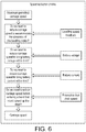
- the Statutory Top Speed is the maximum permissible speed at which the reference point on the chair may travel.
- the True Chair Speed is monitored in real time, in the manner described above, compared with the Statutory Top Speed and, if necessary adjustment made to the Carriage Speed to maintain True Chair Speed below the permissible maximum.
- Battery Voltage is monitored and the Carriage Speed adjusted, if necessary, to maintain the battery voltage at or just above the permitted level. Battery Voltage will also vary as the carriage moves through a transition bend in the rail and the levelling motor operates to maintain the chair level. In this event the overall battery demand will inevitably reduce the battery capacity available to the main carriage motor. Motor Current is also monitored as an influence on carriage speed. Motor current will vary according to passenger weight and according to whether the carriage is moving up the rail or down the rail. Thus the ECU 30 can monitor the Motor Current in real time against a maximum permissible current draw and adjust Carriage Speed to maintain the Motor Current close to the limit and the speed as close as possible to the maximum permitted speed.
- a further factor to be added into the determination of Carriage Speed is levelling under-speed. This takes into account the fact that as the carriage moves through a transition bend in the rail, the levelling motor 21 operates to maintain the chair level. If the carriage motor speed is not matched appropriately to the levelling motor speed, the chair could go 'off level' to an impermissible extent.
- a Maximum Permitted Carriage Speed is prescribed which may be the maximum speed permitted prescribed by regulation or may be another maximum speed programmed into the ECU.
- the first factor shown in Figure 6 influencing this maximum speed is a feedback signal from the levelling motor, which signal may lead to a reduction in the speed of the carriage motor to ensure that the chair does not go off-level because of the relative slowness of the levelling motor as the carriage moves through a transition bend in the rail.
- the ECU looks at Battery Voltage and, if necessary, adjusts the Maximum Permitted Carriage Speed to bring the battery voltage within permissible limits. Similarly the ECU looks at Battery Current and, if necessary, reduces Maximum Permitted Carriage Speed to bring the battery current within limit.
- ECU looks at speed deltas as the carriage moves along the rail, in the manner described above, and adjusts the Maximum Permitted Carriage Speed to maintain speed deltas at levels which ensure passenger comfort.
- the resultant output Carriage Speed can be applied to a conventional PID loop (not shown) to rotate the motor 13 at the speed demanded.
- feedback control is provided by encoder 33.
- the present invention provides a novel method and system for controlling stairlift speed in which the speed at any point along the rail is not set arbitrarily or to fixed limits but, rather, is determined in real time in response to a number of continually varying parameters.
- the system can continually adapt to these varying parameters to output varying speeds and thus allow a reduced overall journey time to be realized.
Landscapes
- Engineering & Computer Science (AREA)
- Transportation (AREA)
- Automation & Control Theory (AREA)
- Structural Engineering (AREA)
- Mechanical Engineering (AREA)
- Rehabilitation Tools (AREA)
- Seats For Vehicles (AREA)
Claims (11)
- Verfahren zum Steuern der Geschwindigkeit eines Treppenlifts (10), der Folgendes aufweist:- eine Schiene (11), die mindestens eine Krümmung (A, C, E, F) aufweist;- ein Fahrgestell (12), das auf der Schiene montiert ist;- einen elektrischen Fahrgestellantriebsmotor (13), der betreibbar ist, um das Fahrgestell (12) entlang der Schiene (11) zu bewegen;- mindestens eine Batterie, um den Fahrgestellantriebsmotor (13) zu versorgen; und- einen Stuhl (16), der auf das Fahrgestell (12) montiert ist,wobei das Verfahren Folgendes umfassti) Erzeugen eines ersten Signals, das für den Strom repräsentativ ist, der von dem Fahrgestellantriebsmotor (13) aufgenommen wird;ii) Erzeugen eines zweiten Signals, das für einen Spannungspegel in der mindestens einen Batterie oder der Leistungsaufnahme aus der Batterie repräsentativ ist;Verfahren gekennzeichnet durch:
iii) das Erzeugen eines oder mehrerer dritter Signale, die für die Geschwindigkeit eines Bezugspunkts (35) auf dem Stuhl repräsentativ sind,
und:
Verwenden des ersten, zweiten und dritten Signals als Steuerungen über die Geschwindigkeit des Fahrgestellantriebsmotors (13). - Verfahren nach Anspruch 1, wobei das Fahrgestell (12) bezüglich dem Stuhl (16) drehbar ist, wobei das Verfahren das Erzeugen eines Signals aufweist, das für die relative Winkelgeschwindigkeit zwischen dem Fahrgestell und dem Stuhl repräsentativ ist, während sich das Fahrgestell durch eine Übergangskrümmung (A, C) in der Schiene bewegt.
- Verfahren nach Anspruch 2, das weiter das Vergleichen der relativen Winkelgeschwindigkeit mit der Drehzahl des Fahrgestellantriebsmotor (13) aufweist, und, falls erforderlich, das Einstellen der Drehzahl des Fahrgestellantriebsmotor, um sicherzustellen, dass der Stuhl (16) im Wesentlichen eben gehalten wird.
- Verfahren nach einem der vorstehenden Ansprüche, das das Erzeugen eines Signals aufweist, das für die Winkelgeschwindigkeit des Fahrgestells repräsentativ ist, während sich das Fahrgestell (12) durch eine horizontale Krümmung (E, F) in der Schiene bewegt.
- Verfahren nach einem der Ansprüche 1 bis 4, wobei die Messung der Drehgeschwindigkeiten des Fahrgestells unter Verwenden eines oder mehrerer Gyroskope (31), die in oder auf dem Fahrgestell und/oder dem Stuhl montiert sind, ausgeführt wird.
- Verfahren nach Anspruch 5, wobei Signale aus dem einen oder den mehreren Gyroskopen (31) verarbeitet werden, um die Geschwindigkeit des Bezugspunkts (35) auf dem Stuhl zu ermitteln.
- Verfahren nach einem der vorstehenden Ansprüche, das weiter das Einstellen der Geschwindigkeit des Fahrgestells präventiv bezüglich der Position des Fahrgestells auf der Schiene umfasst.
- Verfahren nach Anspruch 7, das das Lernen und Speichern in einem Speicher akzeptabler Geschwindigkeitsänderungen an diversen Positionen auf der Schiene (11) umfasst.
- Treppenlift (10), der Folgendes aufweist- eine Schiene (11), die mindestens eine Krümmung (A, C, E, F) aufweist;- ein Fahrgestell (12), das auf der Schiene montiert ist;- einen elektrischen Fahrgestellantriebsmotor (13), der betreibbar ist, um das Fahrgestell (12) entlang der Schiene (11) zu bewegen;- mindestens eine Batterie zum Versorgen des Fahrgestellantriebsmotor (13) mit Leistung; und- einen Stuhl (16), der auf das Fahrgestell (12) montiert ist;wobei der Treppenlift weiter eine Geschwindigkeitssteuervorrichtung aufweist, die konfiguriert ist, umi) ein erstes Signal zu erzeugen, das für Strom, der von dem elektrischen Fahrgestellantriebsmotor bezogen wird, repräsentativ ist,ii) ein zweites Signal zu erzeugen, das für einen Spannungspegel in der mindestens einen Batterie oder der Leistungsaufnahme aus der Batterie repräsentativ ist;dadurch gekennzeichnet, dass die Geschwindigkeitssteuervorrichtung weiter konfiguriert ist, um
iii) ein oder mehrere dritte Signale zu erzeugen, die für die Geschwindigkeit eines Bezugspunkts (35) auf dem Stuhl (16) repräsentativ sind; und
das erste, zweite und dritte Signal als Steuerungen über die Drehzahl des Fahrgestellantriebsmotors (13) anzulegen. - Treppenlift nach Anspruch 9, wobei die Geschwindigkeitssteuervorrichtung ein oder mehrere Gyroskope (31) aufweist, die auf oder in dem Fahrgestell (12) und/oder dem Stuhl (16) montiert sind, um ein oder mehrere erste Signale zu erzeugen.
- Treppenlift nach Anspruch 9 oder Anspruch 10, wobei die Geschwindigkeitssteuervorrichtung ein dreiachsiges Gyroskop (31), das in dem Fahrgestell (12) montiert ist, aufweist.
Applications Claiming Priority (2)
| Application Number | Priority Date | Filing Date | Title |
|---|---|---|---|
| GB1505467.9A GB2536909A (en) | 2015-03-30 | 2015-03-30 | Improvements in or relating to stairlifts |
| PCT/GB2016/050867 WO2016156822A1 (en) | 2015-03-30 | 2016-03-29 | Improvements in or relating to stairlifts |
Publications (2)
| Publication Number | Publication Date |
|---|---|
| EP3277613A1 EP3277613A1 (de) | 2018-02-07 |
| EP3277613B1 true EP3277613B1 (de) | 2019-03-27 |
Family
ID=53178379
Family Applications (1)
| Application Number | Title | Priority Date | Filing Date |
|---|---|---|---|
| EP16715041.6A Active EP3277613B1 (de) | 2015-03-30 | 2016-03-29 | Steuern der geschwindigkeit eines treppenlifts |
Country Status (5)
| Country | Link |
|---|---|
| US (1) | US10752467B2 (de) |
| EP (1) | EP3277613B1 (de) |
| CN (1) | CN107428508B (de) |
| GB (1) | GB2536909A (de) |
| WO (1) | WO2016156822A1 (de) |
Families Citing this family (10)
| Publication number | Priority date | Publication date | Assignee | Title |
|---|---|---|---|---|
| GB2535542A (en) * | 2015-02-23 | 2016-08-24 | Stannah Stairlifts Ltd | Improvements in or relating to stairlifts |
| GB2542822B (en) * | 2015-09-30 | 2021-03-24 | Acorn Mobility Services Ltd | Lift system and method |
| DE102017202010A1 (de) * | 2017-02-08 | 2018-08-09 | Thyssenkrupp Ag | Treppenaufzug |
| DE102017203774A1 (de) * | 2017-03-08 | 2018-09-13 | Thyssenkrupp Ag | Verfahren zum Steuern eines Treppenlifts und Treppenlift |
| GB2565076B (en) * | 2017-07-31 | 2022-03-02 | Stannah Stairlifts Ltd | Improvements in or relating to stairlifts |
| GB201712745D0 (en) * | 2017-08-09 | 2017-09-20 | Stannah Stairlifts Ltd | Improvements in or relating to stairlifts |
| GB2572805B (en) * | 2018-04-12 | 2022-07-13 | Stannah Stairlifts Ltd | Improvements in or relating to stairlifts |
| US11691850B2 (en) * | 2018-08-21 | 2023-07-04 | Tk Home Solutions B.V. | Method of configuring a platform lift |
| CN116409694B (zh) * | 2021-12-31 | 2025-11-04 | 湖南大举信息科技有限公司 | 用于智能并行电梯系统的轿厢姿态调整装置及调整方法 |
| ES3059704T3 (en) * | 2023-01-30 | 2026-03-23 | Tk Home Solutions B V | Method to operate a stairlift with two speed profiles |
Family Cites Families (14)
| Publication number | Priority date | Publication date | Assignee | Title |
|---|---|---|---|---|
| GB9400056D0 (en) | 1994-01-05 | 1994-03-02 | Stannah Stairlifts Ltd | Stairlift levelling arrangement |
| AU2001257322A1 (en) * | 2000-05-05 | 2001-11-20 | Advanced Materials Corporation | Motor controller system for battery-powered motors |
| ITMI20051904A1 (it) * | 2005-10-10 | 2007-04-11 | Vimec S P A | SERVOSCALA CON MEZZI DIMPèOSIZIONAMENTO ANGOLARE |
| US20130231814A1 (en) * | 2006-03-06 | 2013-09-05 | Sterraclimb Llc | Stair-climbing surveillance vehicle |
| US20080128213A1 (en) * | 2006-11-30 | 2008-06-05 | Harris Timothy R | Combination electrical and battery-powered control system for stairway chairlift |
| NL2002503C2 (en) | 2009-02-06 | 2010-08-09 | Ooms Otto Bv | Apparatus for transporting a load from a first to a second level, in particular a stairlift. |
| CN201647771U (zh) | 2009-04-20 | 2010-11-24 | 张克林 | 一种带有远程求助功能接口的曲线型提升装置 |
| CN102259780B (zh) * | 2011-03-17 | 2013-11-27 | 太仓市康辉科技发展有限公司 | 楼梯曲线导轨爬升机器人的控制系统 |
| CN202130964U (zh) * | 2011-05-19 | 2012-02-01 | 哈尔滨工程大学 | 悬挂牵引式座椅电梯 |
| GB2495953B (en) * | 2011-10-26 | 2015-11-18 | Acorn Mobility Services Ltd | Lift system |
| US9004201B2 (en) * | 2012-04-18 | 2015-04-14 | Board Of Trustees Of Michigan State University | Jumping robot |
| JP2013245107A (ja) * | 2012-05-29 | 2013-12-09 | Kuma Lift Gijutsu Kenkyusho:Kk | 椅子式階段昇降装置 |
| GB2542488B (en) * | 2012-12-14 | 2019-11-13 | Stannah Stairlifts Ltd | Improvements in or relating to stairlifts |
| NL2010013C2 (en) * | 2012-12-19 | 2014-06-23 | Thyssenkrupp Accessibility B V | Stair lift drive. |
-
2015
- 2015-03-30 GB GB1505467.9A patent/GB2536909A/en not_active Withdrawn
-
2016
- 2016-03-29 WO PCT/GB2016/050867 patent/WO2016156822A1/en not_active Ceased
- 2016-03-29 CN CN201680017087.0A patent/CN107428508B/zh not_active Expired - Fee Related
- 2016-03-29 EP EP16715041.6A patent/EP3277613B1/de active Active
- 2016-03-29 US US15/563,272 patent/US10752467B2/en not_active Expired - Fee Related
Non-Patent Citations (1)
| Title |
|---|
| None * |
Also Published As
| Publication number | Publication date |
|---|---|
| US10752467B2 (en) | 2020-08-25 |
| CN107428508B (zh) | 2019-10-22 |
| WO2016156822A1 (en) | 2016-10-06 |
| CN107428508A (zh) | 2017-12-01 |
| EP3277613A1 (de) | 2018-02-07 |
| GB2536909A (en) | 2016-10-05 |
| US20180072537A1 (en) | 2018-03-15 |
| GB201505467D0 (en) | 2015-05-13 |
Similar Documents
| Publication | Publication Date | Title |
|---|---|---|
| US10752467B2 (en) | In or relating to stairlifts | |
| EP3261972B1 (de) | Geschwindigkeitsregelung für einen treppenaufzug | |
| US9610862B2 (en) | Seat position sensing and adjustment | |
| EP2987041B1 (de) | Steuerungsvorrichtung für beweglichen körper und steuerungsverfahren für beweglichen körper | |
| CA3090583C (en) | Stairlift system | |
| JPH09207653A (ja) | 車輌用灯具の照射方向制御装置 | |
| JPWO2013014696A1 (ja) | 倒立型移動体制御装置、その制御方法及びプログラム | |
| JP4322960B2 (ja) | エレベータの減速方法および装置 | |
| EP2338775A1 (de) | Selbstangetriebenes fahrzeug und vorrichtung und verfahren zur steuerung desselben | |
| JP2001511757A (ja) | 階段昇降機 | |
| JP6485789B1 (ja) | 鉄道模型列車の自動運転装置及びその加減速度の自動調整方法 | |
| EP3819244B1 (de) | Aufzugssystem mit ohrkomfortanwendung für fahrgäste | |
| JP5772373B2 (ja) | 倒立型移動体制御装置、及びその制御方法 | |
| GB2527410A (en) | Lift system | |
| JP4594757B2 (ja) | 電気車の走行制御装置 | |
| KR20150146177A (ko) | 전동식 파워 스티어링 시스템 및 이를 사용한 차량 쏠림 보상 방법 | |
| CN117325601A (zh) | 车辆底盘平衡控制方法、电子设备及存储介质 | |
| JP2019139005A (ja) | バランス訓練装置 | |
| JP2016049951A (ja) | 倒立二輪型移動体システム及びその制御方法 | |
| JPH11256923A (ja) | 電動間仕切の走行制御方法及びその装置 |
Legal Events
| Date | Code | Title | Description |
|---|---|---|---|
| STAA | Information on the status of an ep patent application or granted ep patent |
Free format text: STATUS: THE INTERNATIONAL PUBLICATION HAS BEEN MADE |
|
| PUAI | Public reference made under article 153(3) epc to a published international application that has entered the european phase |
Free format text: ORIGINAL CODE: 0009012 |
|
| STAA | Information on the status of an ep patent application or granted ep patent |
Free format text: STATUS: REQUEST FOR EXAMINATION WAS MADE |
|
| 17P | Request for examination filed |
Effective date: 20170830 |
|
| AK | Designated contracting states |
Kind code of ref document: A1 Designated state(s): AL AT BE BG CH CY CZ DE DK EE ES FI FR GB GR HR HU IE IS IT LI LT LU LV MC MK MT NL NO PL PT RO RS SE SI SK SM TR |
|
| AX | Request for extension of the european patent |
Extension state: BA ME |
|
| DAV | Request for validation of the european patent (deleted) | ||
| DAX | Request for extension of the european patent (deleted) | ||
| GRAP | Despatch of communication of intention to grant a patent |
Free format text: ORIGINAL CODE: EPIDOSNIGR1 |
|
| STAA | Information on the status of an ep patent application or granted ep patent |
Free format text: STATUS: GRANT OF PATENT IS INTENDED |
|
| INTG | Intention to grant announced |
Effective date: 20181025 |
|
| GRAS | Grant fee paid |
Free format text: ORIGINAL CODE: EPIDOSNIGR3 |
|
| GRAA | (expected) grant |
Free format text: ORIGINAL CODE: 0009210 |
|
| STAA | Information on the status of an ep patent application or granted ep patent |
Free format text: STATUS: THE PATENT HAS BEEN GRANTED |
|
| AK | Designated contracting states |
Kind code of ref document: B1 Designated state(s): AL AT BE BG CH CY CZ DE DK EE ES FI FR GB GR HR HU IE IS IT LI LT LU LV MC MK MT NL NO PL PT RO RS SE SI SK SM TR |
|
| REG | Reference to a national code |
Ref country code: GB Ref legal event code: FG4D |
|
| REG | Reference to a national code |
Ref country code: CH Ref legal event code: EP |
|
| REG | Reference to a national code |
Ref country code: AT Ref legal event code: REF Ref document number: 1112805 Country of ref document: AT Kind code of ref document: T Effective date: 20190415 |
|
| REG | Reference to a national code |
Ref country code: IE Ref legal event code: FG4D |
|
| REG | Reference to a national code |
Ref country code: DE Ref legal event code: R096 Ref document number: 602016011588 Country of ref document: DE |
|
| REG | Reference to a national code |
Ref country code: NL Ref legal event code: FP |
|
| PG25 | Lapsed in a contracting state [announced via postgrant information from national office to epo] |
Ref country code: LT Free format text: LAPSE BECAUSE OF FAILURE TO SUBMIT A TRANSLATION OF THE DESCRIPTION OR TO PAY THE FEE WITHIN THE PRESCRIBED TIME-LIMIT Effective date: 20190327 Ref country code: FI Free format text: LAPSE BECAUSE OF FAILURE TO SUBMIT A TRANSLATION OF THE DESCRIPTION OR TO PAY THE FEE WITHIN THE PRESCRIBED TIME-LIMIT Effective date: 20190327 Ref country code: SE Free format text: LAPSE BECAUSE OF FAILURE TO SUBMIT A TRANSLATION OF THE DESCRIPTION OR TO PAY THE FEE WITHIN THE PRESCRIBED TIME-LIMIT Effective date: 20190327 Ref country code: NO Free format text: LAPSE BECAUSE OF FAILURE TO SUBMIT A TRANSLATION OF THE DESCRIPTION OR TO PAY THE FEE WITHIN THE PRESCRIBED TIME-LIMIT Effective date: 20190627 |
|
| PG25 | Lapsed in a contracting state [announced via postgrant information from national office to epo] |
Ref country code: BG Free format text: LAPSE BECAUSE OF FAILURE TO SUBMIT A TRANSLATION OF THE DESCRIPTION OR TO PAY THE FEE WITHIN THE PRESCRIBED TIME-LIMIT Effective date: 20190627 Ref country code: GR Free format text: LAPSE BECAUSE OF FAILURE TO SUBMIT A TRANSLATION OF THE DESCRIPTION OR TO PAY THE FEE WITHIN THE PRESCRIBED TIME-LIMIT Effective date: 20190628 Ref country code: LV Free format text: LAPSE BECAUSE OF FAILURE TO SUBMIT A TRANSLATION OF THE DESCRIPTION OR TO PAY THE FEE WITHIN THE PRESCRIBED TIME-LIMIT Effective date: 20190327 Ref country code: RS Free format text: LAPSE BECAUSE OF FAILURE TO SUBMIT A TRANSLATION OF THE DESCRIPTION OR TO PAY THE FEE WITHIN THE PRESCRIBED TIME-LIMIT Effective date: 20190327 Ref country code: HR Free format text: LAPSE BECAUSE OF FAILURE TO SUBMIT A TRANSLATION OF THE DESCRIPTION OR TO PAY THE FEE WITHIN THE PRESCRIBED TIME-LIMIT Effective date: 20190327 |
|
| REG | Reference to a national code |
Ref country code: AT Ref legal event code: MK05 Ref document number: 1112805 Country of ref document: AT Kind code of ref document: T Effective date: 20190327 |
|
| PG25 | Lapsed in a contracting state [announced via postgrant information from national office to epo] |
Ref country code: CZ Free format text: LAPSE BECAUSE OF FAILURE TO SUBMIT A TRANSLATION OF THE DESCRIPTION OR TO PAY THE FEE WITHIN THE PRESCRIBED TIME-LIMIT Effective date: 20190327 Ref country code: RO Free format text: LAPSE BECAUSE OF FAILURE TO SUBMIT A TRANSLATION OF THE DESCRIPTION OR TO PAY THE FEE WITHIN THE PRESCRIBED TIME-LIMIT Effective date: 20190327 Ref country code: SK Free format text: LAPSE BECAUSE OF FAILURE TO SUBMIT A TRANSLATION OF THE DESCRIPTION OR TO PAY THE FEE WITHIN THE PRESCRIBED TIME-LIMIT Effective date: 20190327 Ref country code: ES Free format text: LAPSE BECAUSE OF FAILURE TO SUBMIT A TRANSLATION OF THE DESCRIPTION OR TO PAY THE FEE WITHIN THE PRESCRIBED TIME-LIMIT Effective date: 20190327 Ref country code: EE Free format text: LAPSE BECAUSE OF FAILURE TO SUBMIT A TRANSLATION OF THE DESCRIPTION OR TO PAY THE FEE WITHIN THE PRESCRIBED TIME-LIMIT Effective date: 20190327 Ref country code: PT Free format text: LAPSE BECAUSE OF FAILURE TO SUBMIT A TRANSLATION OF THE DESCRIPTION OR TO PAY THE FEE WITHIN THE PRESCRIBED TIME-LIMIT Effective date: 20190727 Ref country code: AL Free format text: LAPSE BECAUSE OF FAILURE TO SUBMIT A TRANSLATION OF THE DESCRIPTION OR TO PAY THE FEE WITHIN THE PRESCRIBED TIME-LIMIT Effective date: 20190327 |
|
| REG | Reference to a national code |
Ref country code: CH Ref legal event code: PL |
|
| PG25 | Lapsed in a contracting state [announced via postgrant information from national office to epo] |
Ref country code: PL Free format text: LAPSE BECAUSE OF FAILURE TO SUBMIT A TRANSLATION OF THE DESCRIPTION OR TO PAY THE FEE WITHIN THE PRESCRIBED TIME-LIMIT Effective date: 20190327 Ref country code: LU Free format text: LAPSE BECAUSE OF NON-PAYMENT OF DUE FEES Effective date: 20190329 Ref country code: SM Free format text: LAPSE BECAUSE OF FAILURE TO SUBMIT A TRANSLATION OF THE DESCRIPTION OR TO PAY THE FEE WITHIN THE PRESCRIBED TIME-LIMIT Effective date: 20190327 |
|
| REG | Reference to a national code |
Ref country code: BE Ref legal event code: MM Effective date: 20190331 |
|
| PG25 | Lapsed in a contracting state [announced via postgrant information from national office to epo] |
Ref country code: IS Free format text: LAPSE BECAUSE OF FAILURE TO SUBMIT A TRANSLATION OF THE DESCRIPTION OR TO PAY THE FEE WITHIN THE PRESCRIBED TIME-LIMIT Effective date: 20190727 Ref country code: AT Free format text: LAPSE BECAUSE OF FAILURE TO SUBMIT A TRANSLATION OF THE DESCRIPTION OR TO PAY THE FEE WITHIN THE PRESCRIBED TIME-LIMIT Effective date: 20190327 |
|
| REG | Reference to a national code |
Ref country code: DE Ref legal event code: R097 Ref document number: 602016011588 Country of ref document: DE |
|
| PG25 | Lapsed in a contracting state [announced via postgrant information from national office to epo] |
Ref country code: LI Free format text: LAPSE BECAUSE OF NON-PAYMENT OF DUE FEES Effective date: 20190331 Ref country code: MC Free format text: LAPSE BECAUSE OF FAILURE TO SUBMIT A TRANSLATION OF THE DESCRIPTION OR TO PAY THE FEE WITHIN THE PRESCRIBED TIME-LIMIT Effective date: 20190327 Ref country code: CH Free format text: LAPSE BECAUSE OF NON-PAYMENT OF DUE FEES Effective date: 20190331 Ref country code: DK Free format text: LAPSE BECAUSE OF FAILURE TO SUBMIT A TRANSLATION OF THE DESCRIPTION OR TO PAY THE FEE WITHIN THE PRESCRIBED TIME-LIMIT Effective date: 20190327 Ref country code: IE Free format text: LAPSE BECAUSE OF NON-PAYMENT OF DUE FEES Effective date: 20190329 |
|
| PLBE | No opposition filed within time limit |
Free format text: ORIGINAL CODE: 0009261 |
|
| STAA | Information on the status of an ep patent application or granted ep patent |
Free format text: STATUS: NO OPPOSITION FILED WITHIN TIME LIMIT |
|
| PG25 | Lapsed in a contracting state [announced via postgrant information from national office to epo] |
Ref country code: SI Free format text: LAPSE BECAUSE OF FAILURE TO SUBMIT A TRANSLATION OF THE DESCRIPTION OR TO PAY THE FEE WITHIN THE PRESCRIBED TIME-LIMIT Effective date: 20190327 Ref country code: BE Free format text: LAPSE BECAUSE OF NON-PAYMENT OF DUE FEES Effective date: 20190331 |
|
| 26N | No opposition filed |
Effective date: 20200103 |
|
| PG25 | Lapsed in a contracting state [announced via postgrant information from national office to epo] |
Ref country code: TR Free format text: LAPSE BECAUSE OF FAILURE TO SUBMIT A TRANSLATION OF THE DESCRIPTION OR TO PAY THE FEE WITHIN THE PRESCRIBED TIME-LIMIT Effective date: 20190327 |
|
| PG25 | Lapsed in a contracting state [announced via postgrant information from national office to epo] |
Ref country code: MT Free format text: LAPSE BECAUSE OF NON-PAYMENT OF DUE FEES Effective date: 20190329 |
|
| PG25 | Lapsed in a contracting state [announced via postgrant information from national office to epo] |
Ref country code: CY Free format text: LAPSE BECAUSE OF FAILURE TO SUBMIT A TRANSLATION OF THE DESCRIPTION OR TO PAY THE FEE WITHIN THE PRESCRIBED TIME-LIMIT Effective date: 20190327 |
|
| PG25 | Lapsed in a contracting state [announced via postgrant information from national office to epo] |
Ref country code: HU Free format text: LAPSE BECAUSE OF FAILURE TO SUBMIT A TRANSLATION OF THE DESCRIPTION OR TO PAY THE FEE WITHIN THE PRESCRIBED TIME-LIMIT; INVALID AB INITIO Effective date: 20160329 |
|
| PG25 | Lapsed in a contracting state [announced via postgrant information from national office to epo] |
Ref country code: MK Free format text: LAPSE BECAUSE OF FAILURE TO SUBMIT A TRANSLATION OF THE DESCRIPTION OR TO PAY THE FEE WITHIN THE PRESCRIBED TIME-LIMIT Effective date: 20190327 |
|
| P01 | Opt-out of the competence of the unified patent court (upc) registered |
Effective date: 20230523 |
|
| PGFP | Annual fee paid to national office [announced via postgrant information from national office to epo] |
Ref country code: NL Payment date: 20250530 Year of fee payment: 10 |
|
| PGFP | Annual fee paid to national office [announced via postgrant information from national office to epo] |
Ref country code: DE Payment date: 20250529 Year of fee payment: 10 |
|
| PGFP | Annual fee paid to national office [announced via postgrant information from national office to epo] |
Ref country code: GB Payment date: 20250530 Year of fee payment: 10 |
|
| PGFP | Annual fee paid to national office [announced via postgrant information from national office to epo] |
Ref country code: IT Payment date: 20250529 Year of fee payment: 10 |
|
| PGFP | Annual fee paid to national office [announced via postgrant information from national office to epo] |
Ref country code: FR Payment date: 20250529 Year of fee payment: 10 |