EP3277587B1 - Satellitenstrahlerpaneele mit kombination aus versteifung/wärmerohr - Google Patents
Satellitenstrahlerpaneele mit kombination aus versteifung/wärmerohr Download PDFInfo
- Publication number
- EP3277587B1 EP3277587B1 EP16774068.7A EP16774068A EP3277587B1 EP 3277587 B1 EP3277587 B1 EP 3277587B1 EP 16774068 A EP16774068 A EP 16774068A EP 3277587 B1 EP3277587 B1 EP 3277587B1
- Authority
- EP
- European Patent Office
- Prior art keywords
- satellite
- heat pipe
- structural
- radiator panel
- panel
- Prior art date
- Legal status (The legal status is an assumption and is not a legal conclusion. Google has not performed a legal analysis and makes no representation as to the accuracy of the status listed.)
- Active
Links
Images



Classifications
-
- B—PERFORMING OPERATIONS; TRANSPORTING
- B64—AIRCRAFT; AVIATION; COSMONAUTICS
- B64G—COSMONAUTICS; VEHICLES OR EQUIPMENT THEREFOR
- B64G1/00—Cosmonautic vehicles
- B64G1/22—Parts of, or equipment specially adapted for fitting in or to, cosmonautic vehicles
- B64G1/46—Arrangements or adaptations of devices for control of environment or living conditions
- B64G1/50—Arrangements or adaptations of devices for control of environment or living conditions for temperature control
- B64G1/503—Radiator panels
-
- B—PERFORMING OPERATIONS; TRANSPORTING
- B64—AIRCRAFT; AVIATION; COSMONAUTICS
- B64G—COSMONAUTICS; VEHICLES OR EQUIPMENT THEREFOR
- B64G1/00—Cosmonautic vehicles
- B64G1/10—Artificial satellites; Systems of such satellites; Interplanetary vehicles
-
- B—PERFORMING OPERATIONS; TRANSPORTING
- B64—AIRCRAFT; AVIATION; COSMONAUTICS
- B64G—COSMONAUTICS; VEHICLES OR EQUIPMENT THEREFOR
- B64G1/00—Cosmonautic vehicles
- B64G1/22—Parts of, or equipment specially adapted for fitting in or to, cosmonautic vehicles
- B64G1/24—Guiding or controlling apparatus, e.g. for attitude control
- B64G1/28—Guiding or controlling apparatus, e.g. for attitude control using inertia or gyro effect
- B64G1/283—Guiding or controlling apparatus, e.g. for attitude control using inertia or gyro effect using reaction wheels
-
- B—PERFORMING OPERATIONS; TRANSPORTING
- B64—AIRCRAFT; AVIATION; COSMONAUTICS
- B64G—COSMONAUTICS; VEHICLES OR EQUIPMENT THEREFOR
- B64G1/00—Cosmonautic vehicles
- B64G1/22—Parts of, or equipment specially adapted for fitting in or to, cosmonautic vehicles
- B64G1/46—Arrangements or adaptations of devices for control of environment or living conditions
- B64G1/50—Arrangements or adaptations of devices for control of environment or living conditions for temperature control
-
- B—PERFORMING OPERATIONS; TRANSPORTING
- B64—AIRCRAFT; AVIATION; COSMONAUTICS
- B64G—COSMONAUTICS; VEHICLES OR EQUIPMENT THEREFOR
- B64G1/00—Cosmonautic vehicles
- B64G1/22—Parts of, or equipment specially adapted for fitting in or to, cosmonautic vehicles
- B64G1/46—Arrangements or adaptations of devices for control of environment or living conditions
- B64G1/50—Arrangements or adaptations of devices for control of environment or living conditions for temperature control
- B64G1/506—Heat pipes
-
- B—PERFORMING OPERATIONS; TRANSPORTING
- B64—AIRCRAFT; AVIATION; COSMONAUTICS
- B64G—COSMONAUTICS; VEHICLES OR EQUIPMENT THEREFOR
- B64G1/00—Cosmonautic vehicles
- B64G1/22—Parts of, or equipment specially adapted for fitting in or to, cosmonautic vehicles
- B64G1/52—Protection, safety or emergency devices; Survival aids
- B64G1/58—Thermal protection, e.g. heat shields
-
- B—PERFORMING OPERATIONS; TRANSPORTING
- B64—AIRCRAFT; AVIATION; COSMONAUTICS
- B64G—COSMONAUTICS; VEHICLES OR EQUIPMENT THEREFOR
- B64G1/00—Cosmonautic vehicles
- B64G1/22—Parts of, or equipment specially adapted for fitting in or to, cosmonautic vehicles
- B64G1/66—Arrangements or adaptations of apparatus or instruments, not otherwise provided for
-
- F—MECHANICAL ENGINEERING; LIGHTING; HEATING; WEAPONS; BLASTING
- F28—HEAT EXCHANGE IN GENERAL
- F28D—HEAT-EXCHANGE APPARATUS, NOT PROVIDED FOR IN ANOTHER SUBCLASS, IN WHICH THE HEAT-EXCHANGE MEDIA DO NOT COME INTO DIRECT CONTACT
- F28D15/00—Heat-exchange apparatus with the intermediate heat-transfer medium in closed tubes passing into or through the conduit walls ; Heat-exchange apparatus employing intermediate heat-transfer medium or bodies
- F28D15/02—Heat-exchange apparatus with the intermediate heat-transfer medium in closed tubes passing into or through the conduit walls ; Heat-exchange apparatus employing intermediate heat-transfer medium or bodies in which the medium condenses and evaporates, e.g. heat pipes
- F28D15/0233—Heat-exchange apparatus with the intermediate heat-transfer medium in closed tubes passing into or through the conduit walls ; Heat-exchange apparatus employing intermediate heat-transfer medium or bodies in which the medium condenses and evaporates, e.g. heat pipes the conduits having a particular shape, e.g. non-circular cross-section, annular
-
- F—MECHANICAL ENGINEERING; LIGHTING; HEATING; WEAPONS; BLASTING
- F28—HEAT EXCHANGE IN GENERAL
- F28D—HEAT-EXCHANGE APPARATUS, NOT PROVIDED FOR IN ANOTHER SUBCLASS, IN WHICH THE HEAT-EXCHANGE MEDIA DO NOT COME INTO DIRECT CONTACT
- F28D15/00—Heat-exchange apparatus with the intermediate heat-transfer medium in closed tubes passing into or through the conduit walls ; Heat-exchange apparatus employing intermediate heat-transfer medium or bodies
- F28D15/02—Heat-exchange apparatus with the intermediate heat-transfer medium in closed tubes passing into or through the conduit walls ; Heat-exchange apparatus employing intermediate heat-transfer medium or bodies in which the medium condenses and evaporates, e.g. heat pipes
- F28D15/0275—Arrangements for coupling heat-pipes together or with other structures, e.g. with base blocks; Heat pipe cores
-
- F—MECHANICAL ENGINEERING; LIGHTING; HEATING; WEAPONS; BLASTING
- F28—HEAT EXCHANGE IN GENERAL
- F28F—DETAILS OF HEAT-EXCHANGE AND HEAT-TRANSFER APPARATUS, OF GENERAL APPLICATION
- F28F1/00—Tubular elements; Assemblies of tubular elements
- F28F1/10—Tubular elements and assemblies thereof with means for increasing heat-transfer area, e.g. with fins, with projections, with recesses
- F28F1/12—Tubular elements and assemblies thereof with means for increasing heat-transfer area, e.g. with fins, with projections, with recesses the means being only outside the tubular element
- F28F1/14—Tubular elements and assemblies thereof with means for increasing heat-transfer area, e.g. with fins, with projections, with recesses the means being only outside the tubular element and extending longitudinally
- F28F1/16—Tubular elements and assemblies thereof with means for increasing heat-transfer area, e.g. with fins, with projections, with recesses the means being only outside the tubular element and extending longitudinally the means being integral with the element, e.g. formed by extrusion
-
- B—PERFORMING OPERATIONS; TRANSPORTING
- B64—AIRCRAFT; AVIATION; COSMONAUTICS
- B64G—COSMONAUTICS; VEHICLES OR EQUIPMENT THEREFOR
- B64G1/00—Cosmonautic vehicles
- B64G1/22—Parts of, or equipment specially adapted for fitting in or to, cosmonautic vehicles
- B64G1/40—Arrangements or adaptations of propulsion systems
-
- B—PERFORMING OPERATIONS; TRANSPORTING
- B64—AIRCRAFT; AVIATION; COSMONAUTICS
- B64G—COSMONAUTICS; VEHICLES OR EQUIPMENT THEREFOR
- B64G1/00—Cosmonautic vehicles
- B64G1/22—Parts of, or equipment specially adapted for fitting in or to, cosmonautic vehicles
- B64G1/40—Arrangements or adaptations of propulsion systems
- B64G1/402—Propellant tanks; Feeding propellants
-
- F—MECHANICAL ENGINEERING; LIGHTING; HEATING; WEAPONS; BLASTING
- F28—HEAT EXCHANGE IN GENERAL
- F28F—DETAILS OF HEAT-EXCHANGE AND HEAT-TRANSFER APPARATUS, OF GENERAL APPLICATION
- F28F13/00—Arrangements for modifying heat-transfer, e.g. increasing, decreasing
- F28F2013/005—Thermal joints
- F28F2013/006—Heat conductive materials
Definitions
- the present invention relates to earth-orbiting communication satellites
- Communication satellites receive and transmit radio signals from and to the surface of the Earth. Although Earth-orbiting communications satellites have been in use for many years, providing adequate cooling and heat distribution for the thermally sensitive electronics components onboard such satellites continues to be a problem.
- One source is solar radiation. Solar radiation can be absorbed by thermal insulation shields or readily reflected away from the satellite by providing the satellite with a suitably reflective exterior surface.
- a second source of heat is the electronics onboard the satellite. The removal of electronics-generated heat is more problematic since such heat must be collected from various locations within the satellite, transported to a site at which it can be rejected from the satellite, and then radiated into space.
- Passive thermal panels can be used to dissipate heat from satellites.
- the passive thermal panel includes a honeycomb core having heat pipes embedded therein.
- a heat pipe is a closed chamber, typically in the form of tube, having an internal capillary structure which is filled with a working fluid.
- the operating-temperature range of the satellite sets the choice of working fluid; ammonia, ethane and propylene are typical choices.
- Heat input i.e ., from heat- generating electronics
- the evaporated fluid carries the heat towards a colder heat-output section, where heat is rejected as the fluid condenses.
- the rejected heat is absorbed by the cooler surfaces of the heat-output section and then radiated into space.
- the condensate returns to the heat input section (near to heat-generating components) by capillary forces to complete the cycle.
- the honeycomb core is typically a low strength, lightweight material. For this reason among any others, thin, stiff panels or “skins” are disposed on both major surfaces of the honeycomb core. The core is thus “sandwiched” between the skins. The strength of this composite is dependent largely on: (1) the outer skins and (2) an adhesive layer that bonds the honeycomb core and the skins. The panels are very expensive and labor intensive to manufacture but are required nearly everywhere that there are out-of-plane loads or modal concerns.
- a second configuration of a passive thermal panel is simply a solid metallic skin.
- Such skins are, however, structurally inefficient for use in satellites since the skins' bending stiffness scales with the cube of its thickness. Unless expensive and heavy stiffeners are added to increase bending stiffness, such solid skins can only be used over short spans or with very little mass ( i.e., structures) mounted thereto.
- Document EP 1 031 511 A2 describes using various sets of heat pipes to ensure uniform temperature throughout an individual radiator panel.
- the radiators panels are not honeycomb panels, but apparently they contain internal volume; that is, they are not solid radiator panels.
- the heat pipes of this document are located on the inside of the radiator panels for the purpose of mechanical support.
- Document KR 2011 0014856 A describes a thermal control structure for a geostationary satellite.
- the structure is directed to a satellite having passive thermal panels that include a honeycomb.
- Heat pipes are presented that are disposed on the surface of a skin, the purpose of which is to facilitate heat transfer between the inside and the outside of a panel.
- Document US 6 994 153 B2 describes a heat discharger that is made up of a heat pipe and a heat sink that is formed separately from the heat pipe and that is bonded to the heat pipe via solder.
- the panels on which the heat pipes are mounted are honeycomb structures.
- Document EP 2 332 839 A1 describes a heat discharger that is made up of a heat pipe and a heat sink that is formed separately from the heat pipe and that is bonded to the heat pipe via solder.
- Document WO 2011/143642 describes a system of spacecraft radiators comprising pre-formed thermal-transfer modules joined by at least one solid-state welding process.
- Document EP 2 535 276 B1 describes a further space system having a radiator panel on which there is arranged at least one heat pipe for the dissipation of heat, wherein the radiator panel and the at least one heat pipe consist of materials with different coefficients of thermal expansion.
- the present invention provides an improved passive thermal system by coupling heat pipes to the surface of solid metallic radiators.
- the heat pipes serve as structural ribs to stiffen the panels.
- a satellite having a plurality of solid radiator panels according to the invention is disclosed in claim 1.
- the heat pipes are structurally modified to increase their stiffness and that of the panel to which they are attached.
- the modification increases the out-of-plane height of the heat pipe. More particularly, such modifications substantially increase the component of the "area moment-of-inertia" along an axis that is orthogonal to the plane of the radiator panel to which the modified heat pipe is attached.
- the structural modification typically has little if any impact on the heat-transfer capabilities of the heat pipe. And of course, unlike terrestrial applications, wherein fins (usually 10 or more) are used for convective cooling, in the vacuum of space such fins will only radiate, offering far less potential for cooling.
- modified heat pipes in accordance with the invention have no more than two fins extending from its main body (i.e., the bore containing portion of the heat pipe).
- the modified heat pipe has two members extending therefrom. There would be minimal structural benefit to having three or more fins, yet there would be a weight penalty.
- Embodiments of the present invention can be used for all types of satellites (e.g., LEO, GEO, etc.). Before addressing the specifics of the instant passive thermal system, a satellite in which such a system can be used is described.
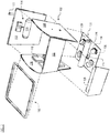
- FIG. 1 depicts satellite 100 in accordance with the present teachings.
- FIG. 2 depicts an "exploded" view of some of the salient features of satellite 100.
- satellite 100 includes unified payload module 102, propulsion module 114, payload antenna module 122, bus component module 132, and solar-array system 140, arranged as shown. It is to be noted that the orientation of satellite 100 in FIGs. 1 and 2 is “upside down” in the sense that in use, antennas 124, which are facing “up” in the figures, would be facing “down” toward Earth.
- Unified payload module 102 comprises panels 104, 106, and 108. In some embodiments, the panels are joined together using various connectors, etc., in known fashion. Brace 109 provides structural reinforcement for the connected panels.
- Panels 104, 106, and 108 serve, among any other functionality, as radiators to radiate heat from satellite 102.
- the panels include adaptations to facilitate heat removal.
- the panels may comprise plural materials such as a core that is sandwiched by face sheets. Materials suitable for use for the panels include those typically used in the aerospace industry.
- the core comprises a lightweight aluminum honeycomb and the face sheets comprise 6061-T6 aluminum, which are bonded together, typically with an epoxy film adhesive,
- Propulsion module 114 is disposed on panel 112, which, in some examples, is constructed in like manner as panels 104, 106, and 108 ( e.g., aluminum honeycomb core and aluminum facesheets, etc.). Panel 112, which is obscured in FIG. 1 , abuts panels 104 and 106 of unified payload module 102.
- Propulsion module 114 includes fuel tank 116 and propulsion control system 118.
- the propulsion control system controls, using one or more valves (not depicted), release of propulsion gas through the propulsion nozzle (not depicted) that is disposed on the outward-facing surface of panel 114.
- Propulsion control system is appropriately instrumented ( i.e., software and hardware) to respond to ground-based commands or commands generated onboard from the control processor.
- Payload antenna module 122 comprises a plurality of antennas 124.
- sixteen antennas 124 are arranged in a 4 x 4 array. In some other embodiments, antennas 124 can be organized in a different arrangement and/or a different number of antennas can be used.
- Antennas 124 are supported by support web 120.
- the support web is a curved panel comprising carbon fiber, with a suitable number of openings ( i.e., sixteen in the illustrative embodiment) for receiving and supporting antennas 124.
- antennas 124 transmit in the K u band, which is the 12 to 18 GHz portion of the electromagnetic spectrum.
- antennas 124 are configured as exponential horns, which are often used for communications satellites.
- the horn antenna transmits radio waves from (or collects them into) a waveguide, typically implemented as a short rectangular or cylindrical metal tube, which is closed at one end and flares into an open-ended horn (conical shaped in the illustrative embodiment) at the other end.
- the waveguide portion of each antenna 124 is obscured in FIG. 1 .
- the closed end of each antenna 124 couples to amplifier(s) (not depicted in FIGs. 1 and 2 ; they are located on the interior surface of panel 104 or 108 ).
- Bus component module 132 is disposed on panel 130, which attaches to the bottom (from the perspective of FIGs. 1 and 2 ) of the unified payload module 102.
- panel 130 can be constructed in like manner as panels 104, 106, and 108 ( e.g ., aluminum honeycomb core and aluminum facesheets, etc. ). In some examples, panel 130 does not include any specific adaptations for heat removal.
- Module 132 includes main solar-array motor 134, four reaction wheels 136, and main control processor 164.
- the reaction wheels enable satellite 100 to rotate in space without using propellant, via conservation of angular momentum.
- Each reaction wheel 136 which includes a centrifugal mass (not depicted), is driven by an associated drive motor (and control electronics) 138.
- drive motor and control electronics
- Only three reaction wheels 136 are required to rotate satellite 100 in the x, y, and z directions.
- the fourth reaction wheel serves as a spare. Such reaction wheels are typically used for this purpose in satellites.
- Main control processor 164 processes commands received from the ground and performs, autonomously, many of the functions of satellite 100, including without limitation, attitude pointing control, propulsion control, and power system control.
- Solar-array system 140 includes solar panels 142A and 142B and respective y-bars 148A and 148B.
- Each solar panel comprises a plurality of solar cells (not depicted; they are disposed on the obscured side of solar panels 142A and 142B) that convert sunlight into electrical energy in known fashion.
- Each of the solar panels includes motor 144 and passive rotary bearing 146; one of the y-bar attaches to each solar panel at motor 144 and bearing 146.
- Motors 144 enable each of the solar panels to at least partially rotate about axis A-A. This facilitates deploying solar panel 142A from its stowed position parallel to and against panel 104 and deploying solar panel 142B from its stowed position parallel to and against panel 106.
- the motors 144 also function to appropriately angle panels 142A and 142B for optimal sun exposure via the aforementioned rotation about axis A-A.
- Member 150 of each y-bar 148A and 148B extends through opening 152 in respective panels 104 and 106.
- members 150 connect to main solar-array motor 134, previously referenced in conjunction with bus component module 132.
- the main solar-array motor is capable of at least partially rotating each member 150 about its axis, as shown. This is for the purpose of angling solar panels 142A and 142B for optimal sun exposure.
- the members 150 can be rotated independently of one another; in some other embodiments, members 150 rotate together.
- Lock-and-release member 154 is used to couple and release solar panel 142A to side panel 104 and solar panel 142B to side panel 106.
- the lock-and-release member couples to opening 156 in side panels 104 and 106.
- Satellite 100 also includes panel 126, which fits "below” (from the perspective of FIGs. 1 and 2 ) panel 108 of unified payload module 102.
- Panel 108 is a sheet of aerospace grade material (e.g., 6061-T6 aluminum, etc.)
- Battery module 128 is disposed on the interior-facing surface of panel 126. The battery module supplies power for various energy consumers onboard satellite 100.
- Battery module 128 is recharged from electricity that is generated via solar panels 142A and 142B; the panels and module 128 are electrically coupled for this purpose (the electrical path between solar panels 142A/B and battery module 128 is not depicted in FIGs, 1 and 2 ).
- Satellite 100 further includes omni-directional antenna 158 for telemetry and ground-based command and control.
- the gateway antennas send and receive user data to gateway stations on Earth.
- the gateway stations are in communication with the Internet.
- Antennas 160 are coupled to panel 108 by movable mounts 162, which enable the antennas to be moved along two axes for optimum positioning with ground-based antennas.
- Antennas 160 typically transmit and receive in the K a band, which covers frequencies in the range of 26.5 to 40 GHz.
- Convertor modules 110 which are disposed on interior-facing surface of panel 106, convert between K a radio frequencies and K u radio frequencies. For example, convertor modules 110 convert the K a band uplink signals from gateway antennas 160 to K u band signals for downlink via antennas 124. Convertor modules 110 also convert in the reverse direction; that is, K u to K a .
- FIG. 3 depicts passive thermal system 300, useful for understanding the invention, which includes a solid radiator panel, such as panels 104, 106, 108, or 112, and one or more heat pipes 370.
- the heat pipes are attached to the panel via an epoxy film adhesive, for example, or other suitable bonding material known to those skilled in the art.
- heat pipes 370 can be bolted to the panels via standard fasteners in conjunction with thermal gasket material, which is compressed between heat pipes 370 and the panel.
- the solid radiator panel is typically formed of a metal, such as aluminum.
- passive thermal system 300 includes three heat pipes 370.
- the heat pipe includes main body 374 and flanges 376.
- Main body 374 includes bore 372. The bore extends the full length of main body 374 and contains heat-pipe fluid.
- the heat pipes are typically formed of aluminum,
- Heat pipes 370 are conventional heat pipes.
- a "conventional heat pipe” is defined for use in this disclosure and the appended claims as a heat pipe having no structural features external to main body 374, other than flanges 376 or other arrangements by which the heat pipe is attached to a surface, or caps that cap the ends of the heat pipe.
- the radiator panels can be subjected to normal compressive and shearing loads. Under certain conditions, these loads can cause a panel to buckle.
- the buckling load of a standard solid radiator panel depends on its thickness; in particular, the thicker the plate (for a given material), the higher the critical buckling load.
- heat pipes 370 on a solid radiator panel provides a second variable that affects buckling load.
- the spacing, s, between the heat pipes naturally decreases.
- the unsupported width of the solid radiator panels i.e., the center-to-center spacing, s, between adjacent heat pipes 370
- adding heat pipes 370 will provide additional buckling resistance to a solid radiator panel.
- increasing width, w, of flange 376 will provide some additional buckling resistance and increase the critical buckling load.
- passive thermal system includes heat pipes that include a physical adaptation for increasing the stiffness of the heat pipes and the combined heat pipes/radiator panel beyond any benefit provided to such a panel by unmodified heat pipes, such as heat pipes 370.
- the stiffness of the heat pipes, and hence passive thermal system 300, can be increased by making the heat pipes taller out-of-plane. This principle is illustrated via FIGs, 9A through 9C .
- FIG. 9A depicts a perspective view of a beam 990.
- FIG. 9B depicts beam 990 oriented such that it is supported at the midpoint of major surface 992B. In this orientation, the "height" of beam 990 is “a”.
- FIG. 9C depicts beam 990 oriented such that it is supported at the midpoint of edge 992B. In this orientation, the "height” of beam 990 is “b” or 6 x a.
- beam 990 will bend in the manner shown far more readily than if the same amount of force were applied to surface 994A as depicted in FIG. 9C . It will be appreciated from these figures that, with height defined as shown and force applied as shown, increasing the height of the beam greatly increases its stiffness to bending in the indicated direction.
- a heat pipe that is modified with the explicit intent of increasing its stiffness without regard to any thermal considerations concerning the heat pipe is referred to in this disclosure and the appended claims as a "structural heat pipe".
- a "structural heat pipe” is defined for use in this disclosure and the appended claims as a heat pipe that is structurally modified to substantially increase the component of the "area moment-of-inertia" along an axis that is orthogonal to the plane of the radiator panel. In this context, “substantially increase” means to increase by 50% or more.
- increasing the component of the "area moment-of-inertia" along an axis that is orthogonal to the plane of the radiator panel means increasing the height of heat pipe, wherein "height” is referenced with respect to the radiator panel to which the structural heat pipe is coupled.
- Embodiments of the present invention do not contemplate using a heat pipe that is larger than what is required for the calculated thermal load.
- embodiments of the invention do not contemplate, and explicitly exclude, using an oversized (based on thermal requirements) heat pipe as a way to increase the aforementioned area moment-of-inertia. Doing so would add too much mass.
- the area moment-of-inertia along an axis that is orthogonal to the plane of the radiator panel heat pipe is increased via structural modifications that typically do not impact the heat-carrying capacity of the heat pipe (e.g., no increase in bore diameter, no structural alterations that result in an increase in the quantity of heat pipe fluid, etc. ) or would have, at best, minimal impact on the heat transfer capabilities of the heat pipe.
- minimal impact means “less than 5 percent”.
- FIGs. 4 through 8 depict, via an end view, passive thermal systems comprising structural heat pipes; that is, heat pipes that are structurally modified to increase their stiffness and that of the attached radiator. It is to be understood that the structures shown in FIGs. 4 through 8 extend "into the page.” In other words, if these Figures were presented via perspective views like FIG. 3 , the structural heat pipes would be seen to extend longitudinally like the conventional heat pipes shown in FIG. 3 .
- FIG. 4 depicts passive thermal system 400 comprising a solid radiator panel, such as panels 104, 106, 108, and 112 and structural heat pipes 470.
- Each structural heat pipe 470 includes a straight vertical fin 480 that extends away from the solid radiator panel and from a position proximal to top 478 of main body 374 of structural heat pipe 470.
- the phrase "top of the main body of the structural heat pipe” means the location on the portion of the heat pipe that contains bore 372 that is furthest from the radiator panel. So, for example, if the FIG. 4 were inverted such that heat pipes 470 were facing "downward," the "top of the main body of the structural heat pipe” is the same location on heat pipes 470 as in FIG. 4 .
- Such a fin is not present on a conventional heat pipe.
- the vertical fin increases the out-of-plane height of heat pipe 470 relative to the unmodified heat pipe 370. This increase in out-of-plane height increases the "area moment-of-inertia" of the heat pipes 470 and the heat pipe/panel assembly ( i.e ., passive thermal system 400 ). The increase in area moment of inertia equates to an increase in stiffness.
- fin 480 is orthogonal to the radiator panel. In some other embodiments, fin 480 is not orthogonal to the radiator panel. The latter case might be dictated, for example, in a situation in which there insufficient clearance for an orthogonally oriented fin.
- a passive thermal system in accordance with the present teachings has two straight vertical fins (each like fin 480 ) that extend away from the solid radiator panel and from a position proximal to top 478 of main body 374 of structural heat pipe 470.
- both fins are orthogonal to the radiator panel.
- the fins can be oriented non-orthogonal to the radiator panel.
- FIG. 5 depicts passive thermal system 500 comprising a solid radiator panel, such as panels 104, 106, 108, and 112 and structural heat pipes 570.
- Each structural heat pipe 570 includes L-shaped fin 580.
- the L-shaped fin increases the out-of-plane height of heat pipe 570 relative to the unmodified heat pipe 370, which, as previously noted, increases the area moment of inertia of the heat pipes 570 and the heat pipe/panel assembly (i.e., passive thermal system 500 ).
- the L-shaped fin requires less out-of-plane clearance than a fin that is straight and has the same amount of mass and the same fin thickness.
- the L-shaped fin also provides more lateral stability to heat pipes 570, which might be required in some embodiments.
- FIG. 6 depicts passive thermal system 600 comprising a solid radiator panel, such as panels 104, 106, 108, and 112 and structural heat pipes 670.
- Each structural heat pipe 670 includes double fin 680.
- the double fin increases the out-of-plane height of heat pipes 670 relative to the unmodified heat pipe 370, and, hence, increases the area moment of inertia of the heat pipes 670 and the heat pipe/panel assembly ( i.e., passive thermal system 600 ).
- double fin 680 also improves the lateral stability of structural heat pipe 670, but is typically preferred to L-shaped fin 580 due to the lack of symmetry of the L-shaped fin.
- FIG. 7 depicts passive thermal system 700 comprising a solid radiator panel, such as panels 104, 106, 108, and 112 and structural heat pipes 770, useful for understanding the invention.
- Each structural heat pipe 770 includes a horizontal plate 780, providing a classic "I-beam" configuration.
- structural heat pipe 770 does not possess the out-of-plane height of, for example, structural heat pipe 470, the I-beam configuration does improve stiffness relative to a conventional heat pipe having the same size.
- FIG. 8 depicts passive thermal system 800 comprising a solid radiator panel, such as panels 104, 106, 108, and 112 and structural heat pipes 870.
- Each structural heat pipe 870 includes vertical fin 880 and horizontal plate 882, providing a "tall" I-beam configuration.
- the additional out-of-plane height of structural heat pipe 870 makes it stiffer than structural heat pipe 770 and, of course, stiffer than unmodified heat pipe 370.
- the main body of the heat pipe is structurally modified.
- a height-increasing feature is coupled to the main body, such as with appropriate fasteners or adhesive.
- heat pipes 370 and structural heat pipes 470 through 870 are depicted as being straight and arranged parallel to one another on a surface of the radiator panel.
- heat pipes 370 and structural heat pipes in accordance with the present teachings are:
Landscapes
- Engineering & Computer Science (AREA)
- Remote Sensing (AREA)
- Physics & Mathematics (AREA)
- Life Sciences & Earth Sciences (AREA)
- Aviation & Aerospace Engineering (AREA)
- Thermal Sciences (AREA)
- General Health & Medical Sciences (AREA)
- Health & Medical Sciences (AREA)
- General Engineering & Computer Science (AREA)
- Mechanical Engineering (AREA)
- Toxicology (AREA)
- Environmental Sciences (AREA)
- Environmental & Geological Engineering (AREA)
- Biodiversity & Conservation Biology (AREA)
- Sustainable Development (AREA)
- Emergency Medicine (AREA)
- Critical Care (AREA)
- Geometry (AREA)
- Astronomy & Astrophysics (AREA)
- General Physics & Mathematics (AREA)
- Chemical & Material Sciences (AREA)
- Combustion & Propulsion (AREA)
- Radar, Positioning & Navigation (AREA)
- Cooling Or The Like Of Electrical Apparatus (AREA)
Claims (16)
- Satellit (100), der eine Mehrzahl von stabilen Radiatorpanelen umfasst, wobei die Radiatorpanele jeweils eine stabile metallische Verkleidung darstellen, um Wärme, die von der im Satelliten enthaltenen Elektronik erzeugt wird, an eine Außenumgebung abzustrahlen, wobei der Satellit (100) ein passives thermisches System (300) umfasst und wobei das passive thermische System umfasst:mindestens eines der stabilen Radiatorpanele (104, 106, 108, 112), undeine Mehrzahl von strukturgebenden Wärmerohren (370, 470, 570, 670, 770, 870), die an dem mindestens einen stabilen Radiatorpanel (104, 106, 108, 112) angeordnet sind und sich auf diesem in Längsrichtung erstrecken,wobei die mehreren strukturgebenden Wärmerohre (370, 470, 570, 670, 770, 870) jeweils einen Grundkörper und einen oberen Abschnitt aufweisen, der sich von dem Radiatorpanel (104, 106, 108, 112) hinweg erstreckt,
dadurch gekennzeichnet, dassdie mehreren strukturgebenden Wärmerohre (370, 470, 570, 670, 770, 870) jeweils nicht mehr als zwei Rippen aufweisen, die sich jeweils von einer Stelle proximal zu dem oberen Abschnitt des Grundkörpers des strukturgebenden Wärmerohrs (370, 470, 570, 670, 770, 870) aus von dem Radiatorpanel (104, 106, 108, 112) hinweg erstrecken,wobei die Rippen jeweils eine strukturgebende Modifikation dahingehend darstellen, als sie die Komponente des Fiächenträgheitsmoments entlang einer Achse orthogonal zu der Ebene der stabilen Radiatorpanel erhöhen, undwobei auf der Oberfläche der stabilen Radiatorpanele (104, 106, 108, 112) keine anderen strukturgebenden Verstärkungen angeordnet sind. - Satellit nach Anspruch 1, wobei die strukturgebende Modifikation zwei gerade Rippen (680) umfasst, die sich von dem stabilen Radiatorpanel (104, 106, 108, 112) hinweg von einer Stelle proximal zu einer Oberseite eines Grundkörpers des strukturgebenden Wärmerohrs (670) ausgehend erstrecken.
- Satellit nach Anspruch 1, wobei die strukturgebende Modifikation eine gerade Rippe (480, 580) umfasst.
- Satellit nach Anspruch 1, wobei die strukturgebende Modifikation zwei Rippen (680) umfasst und wobei die beiden Rippen (680) zusammen eine V-Form bilden, wobei die V-Form einen spitzen Winkel bildet.
- Satellit nach Anspruch 1, wobei die strukturgebende Modifikation ein L-förmiges Element (580) umfasst, wobei das L-förmige Element (580) einen ersten Abschnitt aufweist, der sich von dem stabilen Radiatorpanel (104, 106, 108, 112) hinweg und von einer Stelle proximal zur Oberseite des Grundkörpers des strukturgebenden Wärmerohrs (570) ausgehend erstreckt.
- Satellit nach Anspruch 5, wobei der erste Abschnitt des L-förmigen Elements (580) orthogonal in Bezug auf das stabile Radiatorpanel (104, 106, 108, 112) gerichtet ist.
- Satellit nach Anspruch 5, wobei ein zweiter Abschnitt des L-förmigen Elements (580) parallel in Bezug auf das stabile Radiatorpanel (104, 106, 108, 112) gerichtet ist.
- Satellit nach Anspruch 1, wobei die strukturgebende Modifikation ein T-förmiges Element (780) umfasst, mit einem ersten Abschnitt, der sich von einer Stelle proximal zur Oberseite des Grundkörpers des strukturgebenden Wärmerohrs hinweg erstreckt.
- Satellit nach Anspruch 8, wobei der erste Abschnitt des T-förmigen Elements (780) orthogonal in Bezug auf das stabile Radiatorpanel (104, 106, 108, 112) gerichtet ist.
- Satellit nach Anspruch 9, wobei ein zweiter Abschnitt des T-förmigen Elements (780) parallel in Bezug auf das stabile Radiatorpanel (104, 106, 108, 112) gerichtet ist.
- Satellit nach Anspruch 1, wobei auf der Oberfläche des Radiatorpanels (104, 106, 108, 112) zwei strukturgebende Wärmerohre angeordnet sind, wobei die beiden strukturgebenden Wärmerohre (370, 470, 570, 670, 770, 870) nicht parallel zueinander angeordnet sind.
- Satellit nach Anspruch 1, wobei ein strukturgebendes Wärmerohr (370, 470, 570, 670, 770, 870) nicht geradlinig ausgebildet ist.
- Satellit nach Anspruch 3, wobei sich die eine gerade Rippe (480, 580) von der Oberseite des Grundkörpers des strukturgebenden Wärmerohrs aus erstreckt und zu einem Mittelpunkt zwischen einer linken Seite und einer rechten Seite desselben ausgerichtet ist.
- Satellit nach Anspruch 13, wobei die Rippe (480) orthogonal zu dem stabilen Radiatorpanel (104, 106, 108, 112) angeordnet ist.
- Satellit nach Anspruch 5, wobei der erste Abschnitt zu einem Mittelpunkt zwischen einer linken Seite und einer rechten Seite des Grundkörpers des strukturgebenden Wärmerohrs (370, 470, 570, 670, 770, 870) ausgerichtet ist.
- Satellit nach Anspruch 8, wobei der erste Abschnitt zu einem Mittelpunkt zwischen einer linken Seite und einer rechten Seite des Grundkörpers des strukturgebenden Wärmerohrs (370, 470, 570, 670, 770, 870) ausgerichtet ist.
Applications Claiming Priority (2)
| Application Number | Priority Date | Filing Date | Title |
|---|---|---|---|
| US14/673,215 US10392135B2 (en) | 2015-03-30 | 2015-03-30 | Satellite radiator panels with combined stiffener/heat pipe |
| PCT/US2016/024916 WO2016160924A1 (en) | 2015-03-30 | 2016-03-30 | Satellite radiator panels with combined stiffener/heat pipe |
Publications (3)
| Publication Number | Publication Date |
|---|---|
| EP3277587A1 EP3277587A1 (de) | 2018-02-07 |
| EP3277587A4 EP3277587A4 (de) | 2018-09-05 |
| EP3277587B1 true EP3277587B1 (de) | 2021-06-16 |
Family
ID=57007537
Family Applications (1)
| Application Number | Title | Priority Date | Filing Date |
|---|---|---|---|
| EP16774068.7A Active EP3277587B1 (de) | 2015-03-30 | 2016-03-30 | Satellitenstrahlerpaneele mit kombination aus versteifung/wärmerohr |
Country Status (10)
| Country | Link |
|---|---|
| US (1) | US10392135B2 (de) |
| EP (1) | EP3277587B1 (de) |
| JP (1) | JP6763875B2 (de) |
| KR (1) | KR102124242B1 (de) |
| CN (1) | CN107848635B (de) |
| CA (1) | CA2981169C (de) |
| ES (1) | ES2878080T3 (de) |
| IL (1) | IL254741B (de) |
| SG (1) | SG11201708018RA (de) |
| WO (1) | WO2016160924A1 (de) |
Families Citing this family (19)
| Publication number | Priority date | Publication date | Assignee | Title |
|---|---|---|---|---|
| FR3030458B1 (fr) * | 2014-12-18 | 2017-01-27 | Airbus Defence & Space Sas | Engin spatial |
| US9745083B2 (en) * | 2015-04-01 | 2017-08-29 | Worldvu Satellites Limited | Method for thermal stabilization of a communications satellite |
| FR3052443B1 (fr) * | 2016-06-10 | 2018-07-06 | Airbus Defence And Space Sas | Engin spatial |
| CN106455450B (zh) * | 2016-11-22 | 2019-01-25 | 上海卫星工程研究所 | 星用热管的高等温性轻量化应用方法 |
| US10780998B1 (en) * | 2017-03-22 | 2020-09-22 | Space Systems/Loral, Llc | Spacecraft design with multiple thermal zones |
| CN107985630A (zh) * | 2017-11-02 | 2018-05-04 | 银河航天(北京)科技有限公司 | 一种多功能结构板 |
| FR3089957B1 (fr) * | 2018-12-18 | 2020-12-18 | Airbus Defence & Space Sas | Procédé de fixation d’un équipement dissipatif, mur de véhicule spatial et véhicule spatial |
| CN109606745B (zh) * | 2019-01-09 | 2021-10-26 | 中国科学院长春光学精密机械与物理研究所 | 一种空间热管辐射器 |
| US11794927B2 (en) | 2019-08-28 | 2023-10-24 | The Boeing Company | Additively manufactured spacecraft panel |
| US11542041B2 (en) * | 2020-05-18 | 2023-01-03 | The Boeing Company | Additively manufactured satellite panel with damping |
| US11827389B2 (en) * | 2020-05-18 | 2023-11-28 | The Boeing Company | Additively manufactured satellite |
| US11802606B2 (en) | 2020-05-18 | 2023-10-31 | The Boeing Company | Planate dynamic isolator |
| US11909110B2 (en) * | 2020-09-30 | 2024-02-20 | The Boeing Company | Additively manufactured mesh horn antenna |
| CA3140352A1 (en) | 2020-12-17 | 2022-06-17 | The Boeing Company | Stacked satellite assemblies and related methods |
| CA3140350A1 (en) | 2020-12-17 | 2022-06-17 | The Boeing Company | Satellite thermal enclosure |
| US12024318B1 (en) * | 2021-09-03 | 2024-07-02 | Blue Origin, Llc | Heat fins for heat dissipation of rocket components |
| US11930622B2 (en) | 2022-01-07 | 2024-03-12 | Dell Products Lp | System and method for a 5G cooling module that directs heat into a thermal loop associated with a processing device |
| US20230322419A1 (en) * | 2022-04-11 | 2023-10-12 | Maxar Space Llc | Radiating coupling heat pipe |
| US12565338B1 (en) * | 2023-03-01 | 2026-03-03 | United States Of America As Represented By The Secretary Of The Air Force | Bidirectional regulating heat pipe network |
Citations (2)
| Publication number | Priority date | Publication date | Assignee | Title |
|---|---|---|---|---|
| WO2011143642A2 (en) * | 2010-05-14 | 2011-11-17 | Paragon Space Development Corporation | Radiator systems |
| EP2535276B1 (de) * | 2011-06-16 | 2014-07-30 | Astrium GmbH | Raumfahrtsystem mit einer gekühlten Radiatorplatte |
Family Cites Families (24)
| Publication number | Priority date | Publication date | Assignee | Title |
|---|---|---|---|---|
| DE843333C (de) | 1949-03-29 | 1952-07-07 | Josef Hausmann | Einrichtung an Rohrleitungen zur Vergroesserung der Stuetzweiten |
| JPS6037119A (ja) | 1983-08-08 | 1985-02-26 | Semiconductor Energy Lab Co Ltd | プラズマ気相反応装置 |
| JPS60134601A (ja) | 1983-12-23 | 1985-07-17 | Fujitsu Ltd | 超高周波電力分配器 |
| JPS6243900A (ja) | 1985-08-21 | 1987-02-25 | Toshiba Corp | 不揮発性半導体記憶装置 |
| JPH0535040Y2 (de) * | 1985-09-03 | 1993-09-06 | ||
| JPS6296200A (ja) | 1985-10-23 | 1987-05-02 | 日本電気株式会社 | 高熱伝達ハニカムパネル |
| US4706740A (en) | 1987-03-11 | 1987-11-17 | The United States Of America As Represented By The Secretary Of The Air Force | Ventable survivable heat pipe vapor chamber spacecraft radiator |
| US4880050A (en) * | 1988-06-20 | 1989-11-14 | The Boeing Company | Thermal management system |
| JPH0620976U (ja) * | 1992-05-19 | 1994-03-18 | 善胤 田村 | フィン付きパイプ |
| FR2700609B1 (fr) | 1993-01-18 | 1995-04-07 | Muller Cie | Dispositif de chauffage par rayonnement et convection combinés. |
| US5806803A (en) * | 1995-11-30 | 1998-09-15 | Hughes Electronics Corporation | Spacecraft radiator cooling system |
| US5735489A (en) | 1995-12-22 | 1998-04-07 | Hughes Electronics | Heat transport system for spacecraft integration |
| JP4040125B2 (ja) | 1996-09-18 | 2008-01-30 | ソニー株式会社 | 音声信号記録装置 |
| DE19908683C2 (de) * | 1999-02-26 | 2001-03-01 | Dornier Gmbh | Radiatorstruktur eines Satelliten |
| US6776220B1 (en) * | 1999-08-19 | 2004-08-17 | Space Systems/Loral, Inc | Spacecraft radiator system using crossing heat pipes |
| JP4013543B2 (ja) | 2001-12-28 | 2007-11-28 | 三菱電機株式会社 | 放熱装置 |
| JP3680040B2 (ja) * | 2002-04-22 | 2005-08-10 | 三菱電機株式会社 | ヒートパイプ |
| TWI259051B (en) * | 2005-01-21 | 2006-07-21 | Delta Electronics Inc | Heat dispersion module |
| JP5496212B2 (ja) | 2008-10-02 | 2014-05-21 | イベリカ デル エスパシオ、ソシエダッド アノニマ | 宇宙船のための、熱源からの熱負荷を制御する熱モジュール、及び宇宙船モジュール式熱プラットホーム |
| KR20110014856A (ko) | 2009-08-06 | 2011-02-14 | 한국항공우주연구원 | 정지궤도 위성의 열제어 구조 |
| FR2960218B1 (fr) | 2010-05-21 | 2012-08-03 | Thales Sa | Dispositif de dissipation thermique pour equipement spatial, notamment pour satellite |
| KR101230158B1 (ko) | 2011-10-18 | 2013-02-05 | 김용길 | 모듈형 방열장치 |
| US9403606B2 (en) | 2012-03-06 | 2016-08-02 | The Boeing Company | Spacecraft radiator panels |
| FR3030457B1 (fr) * | 2014-12-17 | 2018-06-01 | Airbus Defence And Space Sas | Engin spatial |
-
2015
- 2015-03-30 US US14/673,215 patent/US10392135B2/en not_active Expired - Fee Related
-
2016
- 2016-03-30 WO PCT/US2016/024916 patent/WO2016160924A1/en not_active Ceased
- 2016-03-30 EP EP16774068.7A patent/EP3277587B1/de active Active
- 2016-03-30 SG SG11201708018RA patent/SG11201708018RA/en unknown
- 2016-03-30 CN CN201680026548.0A patent/CN107848635B/zh not_active Expired - Fee Related
- 2016-03-30 ES ES16774068T patent/ES2878080T3/es active Active
- 2016-03-30 KR KR1020177031249A patent/KR102124242B1/ko not_active Expired - Fee Related
- 2016-03-30 CA CA2981169A patent/CA2981169C/en active Active
- 2016-03-30 JP JP2017551262A patent/JP6763875B2/ja not_active Expired - Fee Related
-
2017
- 2017-09-27 IL IL254741A patent/IL254741B/en unknown
Patent Citations (2)
| Publication number | Priority date | Publication date | Assignee | Title |
|---|---|---|---|---|
| WO2011143642A2 (en) * | 2010-05-14 | 2011-11-17 | Paragon Space Development Corporation | Radiator systems |
| EP2535276B1 (de) * | 2011-06-16 | 2014-07-30 | Astrium GmbH | Raumfahrtsystem mit einer gekühlten Radiatorplatte |
Also Published As
| Publication number | Publication date |
|---|---|
| CA2981169C (en) | 2020-12-29 |
| US10392135B2 (en) | 2019-08-27 |
| EP3277587A4 (de) | 2018-09-05 |
| JP2018511522A (ja) | 2018-04-26 |
| CA2981169A1 (en) | 2016-10-06 |
| IL254741A0 (en) | 2017-11-30 |
| KR102124242B1 (ko) | 2020-06-17 |
| IL254741B (en) | 2022-05-01 |
| KR20170134537A (ko) | 2017-12-06 |
| SG11201708018RA (en) | 2017-10-30 |
| ES2878080T3 (es) | 2021-11-18 |
| CN107848635B (zh) | 2021-02-26 |
| US20160288926A1 (en) | 2016-10-06 |
| JP6763875B2 (ja) | 2020-09-30 |
| EP3277587A1 (de) | 2018-02-07 |
| CN107848635A (zh) | 2018-03-27 |
| WO2016160924A1 (en) | 2016-10-06 |
Similar Documents
| Publication | Publication Date | Title |
|---|---|---|
| CA2981169C (en) | Satellite radiator panels with combined stiffener/heat pipe | |
| US11009297B2 (en) | Fluidicially coupled heat pipes and method therefor | |
| US10793297B2 (en) | Passive thermal system comprising combined heat pipe and phase change material and satellites incorporating same | |
| US6394395B1 (en) | Combination solar array assembly and antenna for a satellite | |
| US8960608B2 (en) | Deployable radiator having an increased view factor | |
| US20150069187A1 (en) | Hosted instrument radiator system | |
| WO2016160987A1 (en) | Satellite frame and method of making a satellite | |
| EP4132850A1 (de) | Wärmeübertragungsanordnungen mit nachgiebigen wärmerohren | |
| CN1922075B (zh) | 有效载荷模块 | |
| US9908643B2 (en) | Passive thermal system providing an embedded interface for heat pipes | |
| US20240140622A1 (en) | Passive thermal radiator structure | |
| EP2956364B1 (de) | Einsetzbare heizung mit erhöhtem sichtfaktor | |
| ES3049644T3 (en) | Heat exchangers for airframes | |
| KR20260064660A (ko) | 중량 불균형 해소 및 전력 효율이 향상된 루프 히트 파이프 기반의 데이터센터용 인공위성 | |
| WO2025184660A1 (en) | Antenna-radiator designs | |
| Thomas et al. | A Modular Thermal Design for Battery in Small satellites | |
| Levine et al. | Conceptual Design for a Space Based Solar Power System-SolPower | |
| Ozaki et al. | System Level Evaluation of Recently Developed Satellite Bus Technologies | |
| Moussessian et al. | Architectural study of active membrane antennas |
Legal Events
| Date | Code | Title | Description |
|---|---|---|---|
| STAA | Information on the status of an ep patent application or granted ep patent |
Free format text: STATUS: THE INTERNATIONAL PUBLICATION HAS BEEN MADE |
|
| PUAI | Public reference made under article 153(3) epc to a published international application that has entered the european phase |
Free format text: ORIGINAL CODE: 0009012 |
|
| STAA | Information on the status of an ep patent application or granted ep patent |
Free format text: STATUS: REQUEST FOR EXAMINATION WAS MADE |
|
| 17P | Request for examination filed |
Effective date: 20171023 |
|
| AK | Designated contracting states |
Kind code of ref document: A1 Designated state(s): AL AT BE BG CH CY CZ DE DK EE ES FI FR GB GR HR HU IE IS IT LI LT LU LV MC MK MT NL NO PL PT RO RS SE SI SK SM TR |
|
| AX | Request for extension of the european patent |
Extension state: BA ME |
|
| RIN1 | Information on inventor provided before grant (corrected) |
Inventor name: ASKIJIAN, ARMEN Inventor name: GROSSMAN, JAMES Inventor name: SMITH, ALEXANDER, D. Inventor name: FIELD, DANIEL, W. |
|
| RIN1 | Information on inventor provided before grant (corrected) |
Inventor name: GROSSMAN, JAMES Inventor name: ASKIJIAN, ARMEN Inventor name: FIELD, DANIEL, W. Inventor name: SMITH, ALEXANDER, D. |
|
| DAV | Request for validation of the european patent (deleted) | ||
| DAX | Request for extension of the european patent (deleted) | ||
| A4 | Supplementary search report drawn up and despatched |
Effective date: 20180806 |
|
| RIC1 | Information provided on ipc code assigned before grant |
Ipc: F28F 1/10 20060101ALN20180727BHEP Ipc: B64G 1/10 20060101ALI20180727BHEP Ipc: B64G 1/50 20060101AFI20180727BHEP Ipc: F28D 15/02 20060101ALI20180727BHEP Ipc: B64G 1/28 20060101ALN20180727BHEP Ipc: B64G 1/58 20060101ALI20180727BHEP Ipc: B64G 1/44 20060101ALI20180727BHEP |
|
| STAA | Information on the status of an ep patent application or granted ep patent |
Free format text: STATUS: EXAMINATION IS IN PROGRESS |
|
| 17Q | First examination report despatched |
Effective date: 20190506 |
|
| RIC1 | Information provided on ipc code assigned before grant |
Ipc: B64G 1/28 20060101ALN20200722BHEP Ipc: B64G 1/50 20060101AFI20200722BHEP Ipc: B64G 1/40 20060101ALN20200722BHEP Ipc: B64G 1/58 20060101ALI20200722BHEP Ipc: F28D 15/02 20060101ALI20200722BHEP Ipc: F28F 1/10 20060101ALN20200722BHEP Ipc: B64G 1/10 20060101ALI20200722BHEP Ipc: B64G 1/44 20060101ALI20200722BHEP Ipc: B64G 1/66 20060101ALN20200722BHEP |
|
| GRAP | Despatch of communication of intention to grant a patent |
Free format text: ORIGINAL CODE: EPIDOSNIGR1 |
|
| RIC1 | Information provided on ipc code assigned before grant |
Ipc: B64G 1/28 20060101ALN20210111BHEP Ipc: B64G 1/58 20060101ALI20210111BHEP Ipc: F28F 1/10 20060101ALN20210111BHEP Ipc: B64G 1/40 20060101ALN20210111BHEP Ipc: F28D 15/02 20060101ALI20210111BHEP Ipc: B64G 1/44 20060101ALI20210111BHEP Ipc: F28F 13/00 20060101ALN20210111BHEP Ipc: F28F 1/16 20060101ALN20210111BHEP Ipc: B64G 1/66 20060101ALN20210111BHEP Ipc: B64G 1/10 20060101ALI20210111BHEP Ipc: B64G 1/50 20060101AFI20210111BHEP |
|
| STAA | Information on the status of an ep patent application or granted ep patent |
Free format text: STATUS: GRANT OF PATENT IS INTENDED |
|
| RIC1 | Information provided on ipc code assigned before grant |
Ipc: F28F 1/16 20060101ALN20210125BHEP Ipc: F28D 15/02 20060101ALI20210125BHEP Ipc: B64G 1/40 20060101ALN20210125BHEP Ipc: B64G 1/44 20060101ALI20210125BHEP Ipc: F28F 1/10 20060101ALN20210125BHEP Ipc: B64G 1/66 20060101ALN20210125BHEP Ipc: B64G 1/10 20060101ALI20210125BHEP Ipc: B64G 1/28 20060101ALN20210125BHEP Ipc: B64G 1/50 20060101AFI20210125BHEP Ipc: F28F 13/00 20060101ALN20210125BHEP Ipc: B64G 1/58 20060101ALI20210125BHEP |
|
| RIC1 | Information provided on ipc code assigned before grant |
Ipc: B64G 1/44 20060101ALI20210203BHEP Ipc: B64G 1/66 20060101ALN20210203BHEP Ipc: B64G 1/40 20060101ALN20210203BHEP Ipc: F28F 1/10 20060101ALN20210203BHEP Ipc: F28D 15/02 20060101ALI20210203BHEP Ipc: F28F 13/00 20060101ALN20210203BHEP Ipc: B64G 1/50 20060101AFI20210203BHEP Ipc: B64G 1/10 20060101ALI20210203BHEP Ipc: F28F 1/16 20060101ALN20210203BHEP Ipc: B64G 1/28 20060101ALN20210203BHEP Ipc: B64G 1/58 20060101ALI20210203BHEP |
|
| INTG | Intention to grant announced |
Effective date: 20210218 |
|
| GRAS | Grant fee paid |
Free format text: ORIGINAL CODE: EPIDOSNIGR3 |
|
| GRAA | (expected) grant |
Free format text: ORIGINAL CODE: 0009210 |
|
| STAA | Information on the status of an ep patent application or granted ep patent |
Free format text: STATUS: THE PATENT HAS BEEN GRANTED |
|
| AK | Designated contracting states |
Kind code of ref document: B1 Designated state(s): AL AT BE BG CH CY CZ DE DK EE ES FI FR GB GR HR HU IE IS IT LI LT LU LV MC MK MT NL NO PL PT RO RS SE SI SK SM TR |
|
| REG | Reference to a national code |
Ref country code: GB Ref legal event code: FG4D |
|
| REG | Reference to a national code |
Ref country code: CH Ref legal event code: EP |
|
| REG | Reference to a national code |
Ref country code: DE Ref legal event code: R096 Ref document number: 602016059408 Country of ref document: DE |
|
| REG | Reference to a national code |
Ref country code: AT Ref legal event code: REF Ref document number: 1402154 Country of ref document: AT Kind code of ref document: T Effective date: 20210715 |
|
| REG | Reference to a national code |
Ref country code: IE Ref legal event code: FG4D |
|
| REG | Reference to a national code |
Ref country code: LT Ref legal event code: MG9D |
|
| RAP4 | Party data changed (patent owner data changed or rights of a patent transferred) |
Owner name: WORLDVU SATELLITES LIMITED |
|
| PG25 | Lapsed in a contracting state [announced via postgrant information from national office to epo] |
Ref country code: BG Free format text: LAPSE BECAUSE OF FAILURE TO SUBMIT A TRANSLATION OF THE DESCRIPTION OR TO PAY THE FEE WITHIN THE PRESCRIBED TIME-LIMIT Effective date: 20210916 Ref country code: HR Free format text: LAPSE BECAUSE OF FAILURE TO SUBMIT A TRANSLATION OF THE DESCRIPTION OR TO PAY THE FEE WITHIN THE PRESCRIBED TIME-LIMIT Effective date: 20210616 Ref country code: FI Free format text: LAPSE BECAUSE OF FAILURE TO SUBMIT A TRANSLATION OF THE DESCRIPTION OR TO PAY THE FEE WITHIN THE PRESCRIBED TIME-LIMIT Effective date: 20210616 Ref country code: LT Free format text: LAPSE BECAUSE OF FAILURE TO SUBMIT A TRANSLATION OF THE DESCRIPTION OR TO PAY THE FEE WITHIN THE PRESCRIBED TIME-LIMIT Effective date: 20210616 |
|
| REG | Reference to a national code |
Ref country code: AT Ref legal event code: MK05 Ref document number: 1402154 Country of ref document: AT Kind code of ref document: T Effective date: 20210616 |
|
| REG | Reference to a national code |
Ref country code: ES Ref legal event code: FG2A Ref document number: 2878080 Country of ref document: ES Kind code of ref document: T3 Effective date: 20211118 |
|
| PG25 | Lapsed in a contracting state [announced via postgrant information from national office to epo] |
Ref country code: GR Free format text: LAPSE BECAUSE OF FAILURE TO SUBMIT A TRANSLATION OF THE DESCRIPTION OR TO PAY THE FEE WITHIN THE PRESCRIBED TIME-LIMIT Effective date: 20210917 Ref country code: LV Free format text: LAPSE BECAUSE OF FAILURE TO SUBMIT A TRANSLATION OF THE DESCRIPTION OR TO PAY THE FEE WITHIN THE PRESCRIBED TIME-LIMIT Effective date: 20210616 Ref country code: RS Free format text: LAPSE BECAUSE OF FAILURE TO SUBMIT A TRANSLATION OF THE DESCRIPTION OR TO PAY THE FEE WITHIN THE PRESCRIBED TIME-LIMIT Effective date: 20210616 Ref country code: SE Free format text: LAPSE BECAUSE OF FAILURE TO SUBMIT A TRANSLATION OF THE DESCRIPTION OR TO PAY THE FEE WITHIN THE PRESCRIBED TIME-LIMIT Effective date: 20210616 Ref country code: NO Free format text: LAPSE BECAUSE OF FAILURE TO SUBMIT A TRANSLATION OF THE DESCRIPTION OR TO PAY THE FEE WITHIN THE PRESCRIBED TIME-LIMIT Effective date: 20210916 |
|
| PG25 | Lapsed in a contracting state [announced via postgrant information from national office to epo] |
Ref country code: EE Free format text: LAPSE BECAUSE OF FAILURE TO SUBMIT A TRANSLATION OF THE DESCRIPTION OR TO PAY THE FEE WITHIN THE PRESCRIBED TIME-LIMIT Effective date: 20210616 Ref country code: CZ Free format text: LAPSE BECAUSE OF FAILURE TO SUBMIT A TRANSLATION OF THE DESCRIPTION OR TO PAY THE FEE WITHIN THE PRESCRIBED TIME-LIMIT Effective date: 20210616 Ref country code: SM Free format text: LAPSE BECAUSE OF FAILURE TO SUBMIT A TRANSLATION OF THE DESCRIPTION OR TO PAY THE FEE WITHIN THE PRESCRIBED TIME-LIMIT Effective date: 20210616 Ref country code: SK Free format text: LAPSE BECAUSE OF FAILURE TO SUBMIT A TRANSLATION OF THE DESCRIPTION OR TO PAY THE FEE WITHIN THE PRESCRIBED TIME-LIMIT Effective date: 20210616 Ref country code: PT Free format text: LAPSE BECAUSE OF FAILURE TO SUBMIT A TRANSLATION OF THE DESCRIPTION OR TO PAY THE FEE WITHIN THE PRESCRIBED TIME-LIMIT Effective date: 20211018 Ref country code: NL Free format text: LAPSE BECAUSE OF FAILURE TO SUBMIT A TRANSLATION OF THE DESCRIPTION OR TO PAY THE FEE WITHIN THE PRESCRIBED TIME-LIMIT Effective date: 20210616 Ref country code: RO Free format text: LAPSE BECAUSE OF FAILURE TO SUBMIT A TRANSLATION OF THE DESCRIPTION OR TO PAY THE FEE WITHIN THE PRESCRIBED TIME-LIMIT Effective date: 20210616 Ref country code: AT Free format text: LAPSE BECAUSE OF FAILURE TO SUBMIT A TRANSLATION OF THE DESCRIPTION OR TO PAY THE FEE WITHIN THE PRESCRIBED TIME-LIMIT Effective date: 20210616 |
|
| PG25 | Lapsed in a contracting state [announced via postgrant information from national office to epo] |
Ref country code: PL Free format text: LAPSE BECAUSE OF FAILURE TO SUBMIT A TRANSLATION OF THE DESCRIPTION OR TO PAY THE FEE WITHIN THE PRESCRIBED TIME-LIMIT Effective date: 20210616 |
|
| REG | Reference to a national code |
Ref country code: DE Ref legal event code: R097 Ref document number: 602016059408 Country of ref document: DE |
|
| PLBE | No opposition filed within time limit |
Free format text: ORIGINAL CODE: 0009261 |
|
| STAA | Information on the status of an ep patent application or granted ep patent |
Free format text: STATUS: NO OPPOSITION FILED WITHIN TIME LIMIT |
|
| PG25 | Lapsed in a contracting state [announced via postgrant information from national office to epo] |
Ref country code: DK Free format text: LAPSE BECAUSE OF FAILURE TO SUBMIT A TRANSLATION OF THE DESCRIPTION OR TO PAY THE FEE WITHIN THE PRESCRIBED TIME-LIMIT Effective date: 20210616 |
|
| 26N | No opposition filed |
Effective date: 20220317 |
|
| PG25 | Lapsed in a contracting state [announced via postgrant information from national office to epo] |
Ref country code: AL Free format text: LAPSE BECAUSE OF FAILURE TO SUBMIT A TRANSLATION OF THE DESCRIPTION OR TO PAY THE FEE WITHIN THE PRESCRIBED TIME-LIMIT Effective date: 20210616 |
|
| PG25 | Lapsed in a contracting state [announced via postgrant information from national office to epo] |
Ref country code: MC Free format text: LAPSE BECAUSE OF FAILURE TO SUBMIT A TRANSLATION OF THE DESCRIPTION OR TO PAY THE FEE WITHIN THE PRESCRIBED TIME-LIMIT Effective date: 20210616 |
|
| REG | Reference to a national code |
Ref country code: CH Ref legal event code: PL |
|
| REG | Reference to a national code |
Ref country code: BE Ref legal event code: MM Effective date: 20220331 |
|
| PG25 | Lapsed in a contracting state [announced via postgrant information from national office to epo] |
Ref country code: LU Free format text: LAPSE BECAUSE OF NON-PAYMENT OF DUE FEES Effective date: 20220330 Ref country code: LI Free format text: LAPSE BECAUSE OF NON-PAYMENT OF DUE FEES Effective date: 20220331 Ref country code: IE Free format text: LAPSE BECAUSE OF NON-PAYMENT OF DUE FEES Effective date: 20220330 Ref country code: CH Free format text: LAPSE BECAUSE OF NON-PAYMENT OF DUE FEES Effective date: 20220331 |
|
| PG25 | Lapsed in a contracting state [announced via postgrant information from national office to epo] |
Ref country code: BE Free format text: LAPSE BECAUSE OF NON-PAYMENT OF DUE FEES Effective date: 20220331 |
|
| PGFP | Annual fee paid to national office [announced via postgrant information from national office to epo] |
Ref country code: FR Payment date: 20230320 Year of fee payment: 8 |
|
| PGFP | Annual fee paid to national office [announced via postgrant information from national office to epo] |
Ref country code: GB Payment date: 20230323 Year of fee payment: 8 Ref country code: DE Payment date: 20230323 Year of fee payment: 8 |
|
| PGFP | Annual fee paid to national office [announced via postgrant information from national office to epo] |
Ref country code: IT Payment date: 20230331 Year of fee payment: 8 Ref country code: ES Payment date: 20230414 Year of fee payment: 8 |
|
| PG25 | Lapsed in a contracting state [announced via postgrant information from national office to epo] |
Ref country code: HU Free format text: LAPSE BECAUSE OF FAILURE TO SUBMIT A TRANSLATION OF THE DESCRIPTION OR TO PAY THE FEE WITHIN THE PRESCRIBED TIME-LIMIT; INVALID AB INITIO Effective date: 20160330 |
|
| PG25 | Lapsed in a contracting state [announced via postgrant information from national office to epo] |
Ref country code: MK Free format text: LAPSE BECAUSE OF FAILURE TO SUBMIT A TRANSLATION OF THE DESCRIPTION OR TO PAY THE FEE WITHIN THE PRESCRIBED TIME-LIMIT Effective date: 20210616 Ref country code: CY Free format text: LAPSE BECAUSE OF FAILURE TO SUBMIT A TRANSLATION OF THE DESCRIPTION OR TO PAY THE FEE WITHIN THE PRESCRIBED TIME-LIMIT Effective date: 20210616 |
|
| REG | Reference to a national code |
Ref country code: DE Ref legal event code: R082 Ref document number: 602016059408 Country of ref document: DE |
|
| PG25 | Lapsed in a contracting state [announced via postgrant information from national office to epo] |
Ref country code: MT Free format text: LAPSE BECAUSE OF FAILURE TO SUBMIT A TRANSLATION OF THE DESCRIPTION OR TO PAY THE FEE WITHIN THE PRESCRIBED TIME-LIMIT Effective date: 20210616 |
|
| REG | Reference to a national code |
Ref country code: DE Ref legal event code: R119 Ref document number: 602016059408 Country of ref document: DE |
|
| GBPC | Gb: european patent ceased through non-payment of renewal fee |
Effective date: 20240330 |
|
| PG25 | Lapsed in a contracting state [announced via postgrant information from national office to epo] |
Ref country code: DE Free format text: LAPSE BECAUSE OF NON-PAYMENT OF DUE FEES Effective date: 20241001 |
|
| PG25 | Lapsed in a contracting state [announced via postgrant information from national office to epo] |
Ref country code: GB Free format text: LAPSE BECAUSE OF NON-PAYMENT OF DUE FEES Effective date: 20240330 |
|
| PG25 | Lapsed in a contracting state [announced via postgrant information from national office to epo] |
Ref country code: FR Free format text: LAPSE BECAUSE OF NON-PAYMENT OF DUE FEES Effective date: 20240331 |
|
| PG25 | Lapsed in a contracting state [announced via postgrant information from national office to epo] |
Ref country code: GB Free format text: LAPSE BECAUSE OF NON-PAYMENT OF DUE FEES Effective date: 20240330 Ref country code: FR Free format text: LAPSE BECAUSE OF NON-PAYMENT OF DUE FEES Effective date: 20240331 Ref country code: DE Free format text: LAPSE BECAUSE OF NON-PAYMENT OF DUE FEES Effective date: 20241001 |
|
| PG25 | Lapsed in a contracting state [announced via postgrant information from national office to epo] |
Ref country code: IT Free format text: LAPSE BECAUSE OF NON-PAYMENT OF DUE FEES Effective date: 20240330 |
|
| REG | Reference to a national code |
Ref country code: ES Ref legal event code: FD2A Effective date: 20250508 |
|
| PG25 | Lapsed in a contracting state [announced via postgrant information from national office to epo] |
Ref country code: ES Free format text: LAPSE BECAUSE OF NON-PAYMENT OF DUE FEES Effective date: 20240331 |
|
| PG25 | Lapsed in a contracting state [announced via postgrant information from national office to epo] |
Ref country code: TR Free format text: LAPSE BECAUSE OF FAILURE TO SUBMIT A TRANSLATION OF THE DESCRIPTION OR TO PAY THE FEE WITHIN THE PRESCRIBED TIME-LIMIT Effective date: 20210616 |