EP3277557B1 - Kugelgewindetrieb und damit ausgestattete lenkung eines kraftfahrzeugs - Google Patents
Kugelgewindetrieb und damit ausgestattete lenkung eines kraftfahrzeugs Download PDFInfo
- Publication number
- EP3277557B1 EP3277557B1 EP16703541.9A EP16703541A EP3277557B1 EP 3277557 B1 EP3277557 B1 EP 3277557B1 EP 16703541 A EP16703541 A EP 16703541A EP 3277557 B1 EP3277557 B1 EP 3277557B1
- Authority
- EP
- European Patent Office
- Prior art keywords
- ball screw
- plain bearing
- housing
- threaded spindle
- screw drive
- Prior art date
- Legal status (The legal status is an assumption and is not a legal conclusion. Google has not performed a legal analysis and makes no representation as to the accuracy of the status listed.)
- Active
Links
Images


Classifications
-
- B—PERFORMING OPERATIONS; TRANSPORTING
- B62—LAND VEHICLES FOR TRAVELLING OTHERWISE THAN ON RAILS
- B62D—MOTOR VEHICLES; TRAILERS
- B62D5/00—Power-assisted or power-driven steering
- B62D5/04—Power-assisted or power-driven steering electrical, e.g. using an electric servo-motor connected to, or forming part of, the steering gear
- B62D5/0442—Conversion of rotational into longitudinal movement
- B62D5/0445—Screw drives
- B62D5/0448—Ball nuts
-
- B—PERFORMING OPERATIONS; TRANSPORTING
- B62—LAND VEHICLES FOR TRAVELLING OTHERWISE THAN ON RAILS
- B62D—MOTOR VEHICLES; TRAILERS
- B62D3/00—Steering gears
- B62D3/02—Steering gears mechanical
- B62D3/04—Steering gears mechanical of worm type
- B62D3/06—Steering gears mechanical of worm type with screw and nut
- B62D3/08—Steering gears mechanical of worm type with screw and nut using intermediate balls or the like
-
- F—MECHANICAL ENGINEERING; LIGHTING; HEATING; WEAPONS; BLASTING
- F16—ENGINEERING ELEMENTS AND UNITS; GENERAL MEASURES FOR PRODUCING AND MAINTAINING EFFECTIVE FUNCTIONING OF MACHINES OR INSTALLATIONS; THERMAL INSULATION IN GENERAL
- F16C—SHAFTS; FLEXIBLE SHAFTS; ELEMENTS OR CRANKSHAFT MECHANISMS; ROTARY BODIES OTHER THAN GEARING ELEMENTS; BEARINGS
- F16C29/00—Bearings for parts moving only linearly
- F16C29/001—Bearings for parts moving only linearly adjustable for alignment or positioning
-
- F—MECHANICAL ENGINEERING; LIGHTING; HEATING; WEAPONS; BLASTING
- F16—ENGINEERING ELEMENTS AND UNITS; GENERAL MEASURES FOR PRODUCING AND MAINTAINING EFFECTIVE FUNCTIONING OF MACHINES OR INSTALLATIONS; THERMAL INSULATION IN GENERAL
- F16C—SHAFTS; FLEXIBLE SHAFTS; ELEMENTS OR CRANKSHAFT MECHANISMS; ROTARY BODIES OTHER THAN GEARING ELEMENTS; BEARINGS
- F16C29/00—Bearings for parts moving only linearly
- F16C29/02—Sliding-contact bearings
-
- F—MECHANICAL ENGINEERING; LIGHTING; HEATING; WEAPONS; BLASTING
- F16—ENGINEERING ELEMENTS AND UNITS; GENERAL MEASURES FOR PRODUCING AND MAINTAINING EFFECTIVE FUNCTIONING OF MACHINES OR INSTALLATIONS; THERMAL INSULATION IN GENERAL
- F16C—SHAFTS; FLEXIBLE SHAFTS; ELEMENTS OR CRANKSHAFT MECHANISMS; ROTARY BODIES OTHER THAN GEARING ELEMENTS; BEARINGS
- F16C33/00—Parts of bearings; Special methods for making bearings or parts thereof
- F16C33/02—Parts of sliding-contact bearings
- F16C33/04—Brasses; Bushes; Linings
-
- F—MECHANICAL ENGINEERING; LIGHTING; HEATING; WEAPONS; BLASTING
- F16—ENGINEERING ELEMENTS AND UNITS; GENERAL MEASURES FOR PRODUCING AND MAINTAINING EFFECTIVE FUNCTIONING OF MACHINES OR INSTALLATIONS; THERMAL INSULATION IN GENERAL
- F16H—GEARING
- F16H25/00—Gearings comprising primarily only cams, cam-followers and screw-and-nut mechanisms
- F16H25/18—Gearings comprising primarily only cams, cam-followers and screw-and-nut mechanisms for conveying or interconverting oscillating or reciprocating motions
- F16H25/20—Screw mechanisms
- F16H25/22—Screw mechanisms with balls, rollers, or similar members between the co-operating parts; Elements essential to the use of such members
- F16H25/2204—Screw mechanisms with balls, rollers, or similar members between the co-operating parts; Elements essential to the use of such members with balls
-
- F—MECHANICAL ENGINEERING; LIGHTING; HEATING; WEAPONS; BLASTING
- F16—ENGINEERING ELEMENTS AND UNITS; GENERAL MEASURES FOR PRODUCING AND MAINTAINING EFFECTIVE FUNCTIONING OF MACHINES OR INSTALLATIONS; THERMAL INSULATION IN GENERAL
- F16C—SHAFTS; FLEXIBLE SHAFTS; ELEMENTS OR CRANKSHAFT MECHANISMS; ROTARY BODIES OTHER THAN GEARING ELEMENTS; BEARINGS
- F16C2326/00—Articles relating to transporting
- F16C2326/20—Land vehicles
- F16C2326/24—Steering systems, e.g. steering rods or columns
-
- F—MECHANICAL ENGINEERING; LIGHTING; HEATING; WEAPONS; BLASTING
- F16—ENGINEERING ELEMENTS AND UNITS; GENERAL MEASURES FOR PRODUCING AND MAINTAINING EFFECTIVE FUNCTIONING OF MACHINES OR INSTALLATIONS; THERMAL INSULATION IN GENERAL
- F16H—GEARING
- F16H25/00—Gearings comprising primarily only cams, cam-followers and screw-and-nut mechanisms
- F16H25/18—Gearings comprising primarily only cams, cam-followers and screw-and-nut mechanisms for conveying or interconverting oscillating or reciprocating motions
- F16H25/20—Screw mechanisms
- F16H2025/2062—Arrangements for driving the actuator
- F16H2025/2096—Arrangements for driving the actuator using endless flexible members
-
- F—MECHANICAL ENGINEERING; LIGHTING; HEATING; WEAPONS; BLASTING
- F16—ENGINEERING ELEMENTS AND UNITS; GENERAL MEASURES FOR PRODUCING AND MAINTAINING EFFECTIVE FUNCTIONING OF MACHINES OR INSTALLATIONS; THERMAL INSULATION IN GENERAL
- F16H—GEARING
- F16H25/00—Gearings comprising primarily only cams, cam-followers and screw-and-nut mechanisms
- F16H25/18—Gearings comprising primarily only cams, cam-followers and screw-and-nut mechanisms for conveying or interconverting oscillating or reciprocating motions
- F16H25/20—Screw mechanisms
- F16H25/24—Elements essential to such mechanisms, e.g. screws, nuts
- F16H2025/2436—Intermediate screw supports for reducing unsupported length of screw shaft
Definitions
- the invention relates to a ball screw and thus equipped steering a motor vehicle.
- the invention relates to a ball screw, which includes a threaded spindle for implementing an auxiliary torque generated by an electric motor in a translational auxiliary force, which acts on a rack in the steering of the motor vehicle.
- the ball screw 10 has a mounted by means of a fixed bearing 4 in a housing 1 ball nut 5, which forms together with the threaded spindle 2a and the rotating balls 6, the essential part of the ball screw and which are around the Rotary axis D can rotate
- the fixed bearing 4 essentially absorbs only axial forces and is thus unloaded in the radial direction.
- the DE-A-10 2008 049701 discloses a ball screw with the features of the preamble of claim 1.
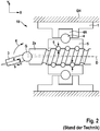
- a conventional ball screw 10 is shown in which the problem arises in everyday use that in particular the transverse force component c of the tie rod force a (generated by the given angle of the respective tie rods 3 in the vehicle) a great challenge to the assembly of a ball screw (KGT) in an EPS steering. If the steering is not able to absorb the very high transverse forces under certain circumstances, there may be damage to the ball screw (hereinafter also referred to as recirculating ball thread) and KGT bearing, which, inter alia, leads to a significant deterioration of the acoustic properties.
- the transverse force component c of the tie rod force a generated by the given angle of the respective tie rods 3 in the vehicle
- KGT ball screw
- the lateral force component c of the tie rod force a to a radial load, ie to a force acting in the radial direction Y lateral load of the ball screw 10.
- This transverse load not only causes the Lead screw 2a and rack 2b can bend elastically, but that forms a corresponding tilting moment K in the ball screw 10.
- the tilting moment K in turn causes a particularly high load on the first ball 6 in the screw drive and the last ball. It will be in Fig. 2 indicated by the arrows.
- High tilting moments are based there in the front or rear of the ball and create a high Hertzian pressure in contact "ball raceway” or “ball ball”, especially in the outer threads of the ball nut 5. This in turn leads to a high Damage and life reduction, deformations in the ball track and / or on the ball, which then a significant acoustic deterioration in the ball screw is the result.
- the invention is therefore based on a conventional ball screw, which includes a threaded spindle for converting an auxiliary torque generated by an electric motor into a translational auxiliary force, which acts on a rack in a steering system of a motor vehicle, wherein one end of the Threaded spindle and one end of the rack are each connected by means of an axial joint with a tie rod, wherein the ball screw by means of a fixed bearing (which can only absorb axial forces) mounted in a housing ball nut.
- Object of the present invention is to significantly improve a ball screw of the type mentioned, so that the above-mentioned disadvantages are overcome in an advantageous manner.
- the ball screw should be designed for installation in steering systems so that even high transverse loads do not lead to high loads in the ball screw of the ball screw.
- the object is achieved by a ball screw with the features of claim 1.
- a steering is proposed, which is equipped with such a ball screw.
- the ball screw according to the invention is characterized in that between the tie rod connected to the end of the threaded spindle and the ball screw a sliding bearing element is arranged, which supports the threaded spindle radially relative to the housing.
- the sliding bearing element is formed as a plain bearing bush which surrounds the threaded spindle, wherein the plain bearing bush is gimbal-mounted in the housing and receives the resulting from the tie rods transverse force component of the rack.
- a threaded spindle radially supporting slide bearing is provided, which can absorb occurring transverse forces, which effectively prevents cross-loads (KGT and KGT camp see only Axial forces) can act directly on the ball circulation or its bearings.
- the invention is realized by a plain bearing bush, which is gimbal-mounted in the housing.
- the invention relates to a steering system for a motor vehicle, which is equipped with such a ball screw, and also relates to a plain bearing element itself, which is suitable for the construction of such a ball screw. Reference is also made to the independent claims.
- the plain bearing bush according to the invention has an annular outer circumference, which is convexly curved, in particular in the form of a spherical cap, is curved.
- annular outer circumference which is convexly curved, in particular in the form of a spherical cap, is curved.
- a half-cardanic bearing of the plain bearing bush is realized in a very efficient manner.
- At least a second portion of the outer circumference of the plain bearing bush abuts on the inner wall of a ring insertable into the housing, which is concavely arched.
- the insertable ring can be fixed with a fixing element in a desired position.
- the plain bearing bush for this purpose has on its outer circumference two grooves, in which the round wire rings are accommodated. Furthermore, it can be provided that the inner wall of the plain bearing bush has a chamfer at both ends of the bush or is chamfered there.
- the plain bearing element or plain bearing bush is preferably made of metal, in particular steel or aluminum, or of plastic, in particular a polyamide.
- Ball screws shown also have such components already in the Fig. 1 and 2 are present and provided with reference numerals. Therefore, the reference numerals for the following components are retained: steering housing GH with steering gear LG and ball screw 10 in the housing (part) 1; Ball nut 5; Interior or ball circulation with balls 6; Threaded spindle 2b with its axis of rotation D; Fixed bearing 4; Rack 2b; Joint G for coupling the respective tie rod 3 or 3 '; Belt R and engine M.
- the Fig. 3 shows in cross section the structure of a steering, which is equipped with a ball screw 10 according to the invention.
- the ball screw 10 includes the threaded spindle 2a, which is formed uniformly with the rack 2b of the steering.
- the overall structure is also referred to simply as a rack.
- a tie rod 3 or 3 ' is pivotally connected.
- a plain bearing element 30 is between the ball screw 10 and the free end of the threaded spindle 2a, ie the end connected to the tie rod 3 arranged, which supports the threaded spindle 2a radially relative to the housing GH.
- the sliding bearing element is designed as a plain bearing bush 30, which surrounds the threaded spindle 2a.
- the bushing 30 consists essentially of an annular body with a smooth inner wall 32 and a convex outer circumference 31.
- this part of the socket in the form of a spherical cap which is about half (right half in Fig. 4b ) is received in a concave shaped portion of the housing GH.
- the other half of the spherical cap 31 (left half in Fig.
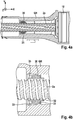
- Fig. 4a / b illustrated embodiment of the invention thus shows a gimbal-mounted and pivotable about the z-axis bushing 30, which supports the threaded spindle 2a radially and can absorb transverse forces (in y-direction).
- the contacting or the game between the Plain bearing bushing 30 and the housing GH can be optimally adjusted via the fixing element 35.
- the bushing itself or the annular body 30 can be cut for purposes of material and weight savings (as in Fig. 4b ). If desired, the incisions or tapers of the material may also be dimensioned relatively weakly for the purpose of a certain elasticity.
- a plain bearing element 40 As a plain bearing element 40, a likewise annular body is used, which has the form of a plain bearing bush and the threaded spindle 2a comprises.
- the inner wall of the plain bearing element or plain bearing bushing 40 is also flat and smooth in the interior.
- the two ends of the sleeve 40 may be chamfered, ie chamfer 42 have. The chamfers facilitate assembly and are advantageous in terms of the bending line and the rotation of the thread.
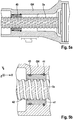
- the bushing 40 On the outer circumference of the bushing 40 grooves are provided, each extending in the direction of rotation and each receive a round wire ring 43 and 44 respectively.
- the round wire ring 43 and 44 contact the inner wall of the housing GH, so that the plain bearing bush is mounted slightly pivotable (gimbal).
- the outer periphery 41 slightly convex and formed, for example in the form of a spherical cap.
- the spherical cap is axially fixed with one of the round wire rings, here with the right ring 44.
- the installation location of the plain bearing bush 30 or 40 should preferably be in the vicinity of the free end of the threaded spindle 2a, so as close as possible connecting joint for the tie rod 3 (see also Fig. 3 ).
- acting on the tie rod lateral force components can be better supported / intercepted.
- the socket 30 or 40 itself consists in the present example of a polyamide of the type PA-6, but can also be made be made of other suitable plastics, alternatively made of metal, such as steel or aluminum.
- the invention is particularly suitable to be installed in the steering of a motor vehicle, in particular in a steering with electric power assistance.
- lighter design or design variants can be realized, since smaller threaded spindle or rack diameter are possible.
- a shorter construction of the ball nut is possible because fewer threads are required.
- the performance or operating characteristics are significantly improved by a non-tensioned ball chain.
- the invention relates to a ball screw 10, which is used in a steering.
- the ball screw 10 includes a screw shaft 2a for converting an auxiliary torque generated by an electric motor M into a translational auxiliary force acting on a rack 2b in the steering of a motor vehicle, one end of the threaded spindle 2a and one end of the rack 2b respectively by means of an axial joint G with a tie rod 3, 3 'are connected, wherein the ball screw 10 has a mounted by means of a fixed bearing 4 in a housing GH ball nut 5.
- a plain bearing element 30 is arranged, which supports the threaded spindle 2a radially relative to the housing GH.
- the sliding bearing element is preferably formed as a plain bearing bush 30, which is gimballed in the housing GH at least about a transverse axis z, which is oriented perpendicular to a direction y, in which a transverse force component c of a tie rod force a occurs.
- the plain bearing bush 30 has an annular outer periphery 31, which is convexly curved, in particular in the form of a spherical cap, is curved. At least a first portion of the convex outer periphery 31 abuts against a concave portion of the inner wall of the housing GH.
- the KGT camp takes advantage of the Storage presented here only on axial forces and can therefore be performed as a pure thrust ball bearing.
Landscapes
- Engineering & Computer Science (AREA)
- General Engineering & Computer Science (AREA)
- Mechanical Engineering (AREA)
- Chemical & Material Sciences (AREA)
- Combustion & Propulsion (AREA)
- Transportation (AREA)
- Power Steering Mechanism (AREA)
- Transmission Devices (AREA)
- Steering-Linkage Mechanisms And Four-Wheel Steering (AREA)
- Bearings For Parts Moving Linearly (AREA)
Description
- Die Erfindung betrifft einen Kugelgewindetrieb und eine damit ausgestattete Lenkung eines Kraftfahrzeugs. Insbesondere betrifft die Erfindung einen Kugelgewindetrieb, der eine Gewindespindel enthält zur Umsetzung eines von einem Elektromotor erzeugten Hilfsdrehmomentes in eine translatorische Hilfskraft, welche auf eine Zahnstange in der Lenkung des Kraftfahrzeugs wirkt.
- Auf dem Gebiet der Kraftfahrzeug-Lenkungen ist es hinlänglich bekannt, Kugelgewindetriebe einzusetzen, um eine von einem Hilfskraftmotor (Elektromotor) erzeugte rotatorische Hilfskraft (Drehmoment) in eine translatorische Hilfskraft umzusetzen, die auf eine Gewindespindel bzw. Zahnstange der Lenkung wirkt. In der
Fig. 1 ist eine solche Konstruktion schematisch dargestellt. Wie dort zu sehen ist, wird über den Kugelgewindetrieb 10 die Gewindespindel 2a bzw. die Zahnstange 2b der Lenkung ausgelenkt, wobei das Ende der Gewindespindel 2a mittels eines Axialgelenks G mit einer Spurstange 3 verbunden ist; am Ende der Zahnstange 2b ist diese entsprechend gelenkig mit einer Spurstange 3' verbunden. Die Zahnstange 2b steht mit dem Ritzel eines Lenkgetriebes L im Eingriff. Der Kugelgewindetrieb 10 wird über einen Riemen R oder dergleichen von einem Elektromotor M angetrieben. In derFig. 2 ist der Aufbau des Kugelgewindetriebes im Detail dargestellt: Der Kugelgewindetrieb 10 weist eine mittels eines Festlagers 4 in einem Gehäuse 1 gelagerte Kugelmutter 5 auf, die zusammen mit der Gewindespindel 2a und den umlaufenden Kugeln 6, den wesentlichen Teil des Kugelgewindetriebes bildet und die sich um die Drehachse D drehen kann Das Festlager 4 nimmt im Wesentlichen nur Axialkräfte auf und ist somit in Radialrichtung unbelastet. - Beispielsweise ist ein solcher Kugelgewindetrieb aus der
DE 10 2012 110 081 A1 bekannt. Diese Art von Kugelgewindetrieb wird häufig in elektrischen Hilfskraft-Lenkungen, sog. EPS-Lenkungen (Electric Power Steering), eingesetzt. - Des Weiteren ist bekannt, z.B. aus der
DE 10 2010 029 266 A1 , einen Kugelgewindetrieb der eingangs genannten Art dahingehend weiterzubilden, dass an jeder Stirnseite des Festlagers, insbesondere am Außenring des Festlagers (s. dortFig. 2 ), mindestens ein Federelement "24" angeordnet wird. Hierdurch wird an dem Festlager eine Elastizität der Lagerung erreicht, wodurch in axialer Richtung wirkende stoßartige Belastungen effektiv gedämpft werden können. - Die
DE-A-10 2008 049701 offenbart einen Kugelgewindetrieb mit den Merkmalen des Oberbegriffs des Anspruchs 1. - In der
Fig. 2 ist ein herkömmlicher Kugelgewindetrieb 10 dargestellt, bei dem sich im alltäglichen Einsatz das Problem stellt, dass insbesondere die Querkraftkomponente c der Spurstangenkraft a (erzeugt durch die gegebenen Winkel der jeweiligen Spurstangen 3 im Fahrzeug) eine große Herausforderung an die Baugruppe eines Kugelgewindetriebs (KGT) in einer EPS-Lenkung darstellt. Ist die Lenkung nicht in der Lage, die unter Umständen sehr hohen Querkräfte aufzunehmen, kann es zu einer Schädigung des Kugelgewindetriebs (nachfolgend auch Kugelumlaufgewinde genannt) und KGT-Lagers kommen, was u.a. zu einer signifikante Verschlechterung der akustischen Eigenschaften führt. Wie in derFig. 2 anhand der grafischen Zerlegung der Spurstangen-Kraft a in die Komponenten b und c zu sehen ist, führt die Querkraftkomponente c der Spurstangenkraft a zu einer Radiallast, d.h. zu einer in Radialrichtung Y wirkenden Querbelastung des Kugelgewindetriebes 10. Diese Querbelastung bewirkt nicht nur, dass die Gewindespindel 2a und Zahnstange 2b sich elastisch verbiegen können, sondern dass sich ein entsprechendes Kippmoment K im Kugelgewindetrieb 10 ausbildet. Das Kippmoment K wiederum bewirkt eine besonders hohe Belastung der ersten Kugel 6 im Gewindetrieb und der letzen Kugel. Die wird inFig. 2 durch die Pfeile angedeutet. Hohe Kippmomente stützen sich dort im vorderen bzw. hinteren Bereich des Kugelumlaufs ab und erzeugen eine hohe Hertzsche Pressung im Kontakt "Kugel-Laufbahn" bzw. "Kugel-Kugel", insbesondere in den äußeren Gewindegängen der Kugelmutter 5. Dies führt wiederum zu einer hohen Schädigung und Lebensdauer-Reduzierung, zur Deformationen in der Kugellaufbahn und/oder an der Kugel, wonach dann eine signifikante akustische Verschlechterung im Kugelgewindetrieb die Folge ist. - Die Erfindung geht also von einem herkömmlichen Kugelgewindetrieb aus, der eine Gewindespindel enthält zur Umsetzung eines von einem Elektromotor erzeugten Hilfsdrehmomentes in eine translatorische Hilfskraft, welche auf eine Zahnstange in einer Lenkung eines Kraftfahrzeugs wirkt, wobei ein Ende der Gewindespindel und ein Ende der Zahnstange jeweils mittels eines Axialgelenks mit einer Spurstange verbunden sind, wobei der Kugelgewindetrieb eine mittels eines Festlagers (das nur Axialkräfte aufnehmen kann) in einem Gehäuse gelagerte Kugelmutter aufweist.
- Aufgabe der vorliegenden Erfindung ist es, einen Kugelgewindetrieb der eingangs genannten Art deutlich zu verbessern, so dass die oben genannten Nachteile in vorteilhafter Weise überwunden werden. Insbesondere soll der Kugelgewindetrieb für den Einbau in Lenkungen so beschaffen sein, dass auch hohe Querbelastungen zu keiner hohen Belastung im Kugelumlauf des Kugelgewindetriebes führen.
- Die Aufgabe wird gelöst durch einen Kugelgewindetrieb mit den Merkmalen des Anspruchs 1. Außerdem wird eine Lenkung vorgeschlagen, die mit einem solchen Kugelgewindetrieb ausgestattet ist.
- Der erfindungsgemäße Kugelgewindetrieb zeichnet sich dadurch aus, dass zwischen dem mit der Spurstange verbundenen Ende der Gewindespindel und dem Kugelgewindetrieb ein Gleitlager-Element angeordnet ist, welches die Gewindespindel radial gegenüber dem Gehäuse abstützt.
- Vorzugsweise ist das Gleitlager-Element als eine Gleitlagerbuchse ausgebildet, welche die Gewindespindel umschließt, wobei die Gleitlagerbuchse in dem Gehäuse kardanisch gelagert ist und die aus den Spurstangen resultierende Querkraftkomponente der Zahnstange aufnimmt.
- Durch die hier offenbarte Erfindung wird zwischen dem Kugelgewindetrieb (kurz: KGT) und der Ankopplung der Spurstange eine die Gewindespindel radial stützende Gleitlagerung vorgesehen, die auftretende Querkräfte abfangen kann, wodurch effektiv verhindert wird, dass Querbelastungen (KGT u. KGT-Lager sehen nur noch Axialkräfte) direkt auf den Kugelumlauf bzw. dessen Lager einwirken können. Vorzugsweise wird die Erfindung durch eine Gleitlagerbuchse realisiert, die in dem Gehäuse kardanisch schwenkbar montiert ist.
- Durch eine sehr dicht an der krafteinleitenden Stelle platzierte Gleitlagerstelle ergeben sich geringere Durchbiegungen der Zahnstange und reduzierte Belastungen auf die Gewindespindel den KGT und des KGT-Lagers. Hierdurch ist es möglich, kleinere Gewindespindel oder Zahnstangen-Durchmesser zu verwenden und auch weniger Gewindegänge im Kugelumlauf vorzusehen, ohne die zulässigen Festigkeiten zu überschreiten. Dadurch kann die Konstruktion der Lenkung sehr kostengünstig realisiert werden. Zudem wird die gesamte Kugelkette weniger belastet, wodurch die Robustheit hinsichtlich der Betriebseigenschaften deutlich steigt.
- Die Erfindung betrifft auf eine Lenkung für ein Kraftfahrzeug, die mit einem solchen Kugelgewindetrieb ausgestattet ist, und betrifft auch ein Gleitlager-Element an sich, das für den Aufbau eines solchen Kugelgewindetriebes geeignet ist. Hierzu wird auch auf die nebengeordneten Ansprüche verwiesen.
- Die oben genannte Vorteile sowie weitere Vorteile ergeben sich auch aus Unteransprüchen, welche vorteilhafte Ausgestaltungen der Erfindung angeben.
- Demnach weist die Gleitlagerbuchse erfindungsgemäß einen ringförmigen Außenumfang auf, der konvex gewölbt ist, insbesondere in Form einer Kugelkalotte, gewölbt ist. In diesem Zusammenhang ist es vorteilhaft, wenn zumindest ein erster Teilbereich des Außenumfangs der Gleitlagerbuchse an einer Innenwandung des Gehäuses anliegt, welche konkav gewölbt ist. Hierdurch wird in sehr effizienter Weise eine halbkardanische Lagerung der Gleitlagerbuchse realisiert.
- Weiter erfindungsgemäß liegt zumindest ein zweiter Teilbereich des Außenumfangs der Gleitlagerbuchse an der Innenwandung eines in das Gehäuse einführbaren Ringes an, welche konkav gewölbt ist. Der einführbare Ring kann mit einem Fixierelement in einer gewünschten Position fixiert werden. Hierdurch wird der Einbau der Gleitlagerbuchse in das Gehäuse vereinfacht; zudem ist die kardanische Lagerung der Buchse auf ein evtl. gewünschtes Spiel hin einstellbar.
- Es kann gemäß einer nicht beanspruchten Variante die Gleitlagerbuchse an ihren beiden Enden von jeweils einem Runddrahtring gegen ein Verschieben in axialer Richtung gesichert sein. Vorzugsweise weist die Gleitlagerbuchse hierfür an ihrem Außenumfang zwei Nuten auf, in welche die Runddrahtringe aufgenommen sind. Des Weiteren kann vorgesehen werden, dass die Innenwandung der Gleitlagerbuchse an beiden Enden der Buchse ein Fase aufweist bzw. dort angefast ist.
- Das Gleitlager-Element bzw. die Gleitlagerbuchse ist vorzugsweis aus Metall, insbesondere Stahl oder Aluminium, oder aus Kunststoff, insbesondere einem Polyamid, gefertigt.
- Nachfolgend wird die Erfindung anhand von Ausführungsbeispielen, die sich auf eine Lenkung für ein Kraftfahrzeug beziehen, im Detail und unter Bezugnahme auf die beiliegenden Zeichnungen
Fig. 3 ,4a /b und 5a/b beschrieben, die folgende schematische Darstellungen wiedergeben: - Fig. 3
- zeigt im Querschnitt den Aufbau einer Lenkung, die mit einem erfindungsgemäßen Kugelgewindetrieb ausgestattet ist;
- Fig. 4a/b
- zeigen im Detail den Einbau eines Gleitlager-Elementes gemäß einem ersten Ausführungsbeispiel in Form einer kardanisch gelagerten Gleitlagerbuchse; und
- Fig. 5a/b
- zeigen im Detail den Einbau eines Gleitlager-Elementes gemäß einem zweiten Ausführungsbeispiel in Form einer mittels Runddrahtringen gesicherten Gleitlagerbuchse.
- Die in den
Fig. 3 und4 dargestellten Kugelgewindetriebe weisen auch solche Komponenten auf, die bereits in denFig. 1 und2 vorhanden sind und mit Bezugszeichen versehen sind. Daher werden die Bezugszeichen für die folgenden Komponenten beibehalten: Lenkungs-Gehäuse GH mit Lenkgetriebe LG und Kugelgewindetrieb 10 im Gehäuse(teil) 1; Kugelmutter 5; Innenbereich bzw. Kugelumlauf mit Kugeln 6; Gewindespindel 2b mit ihrer Drehachse D; Festlager 4; Zahnstange 2b; Gelenk G zur Ankopplung der jeweiligen Spurstange 3 bzw. 3'; Riemen R und Motor M. - Nachfolgend wird zur Beschreibung des ersten Ausführungsbeispiels auf die
Fig. 3 - 5a /b Bezug genommen:
DieFig. 3 zeigt im Querschnitt den Aufbau einer Lenkung, die mit einem erfindungsgemäßen Kugelgewindetrieb 10 ausgestattet ist. Der Kugelgewindetrieb 10 umfasst die Gewindespindel 2a, welche baueinheitlich mit der Zahnstange 2b der Lenkung ausgebildet ist. Das Gesamtgebilde wird auch kurz vereinfachend mit Zahnstange bezeichnet. An beiden freien Enden des Gesamtgebildes ist eine Spurstange 3 bzw. 3' gelenkig angeschlossen. Um nun zu verhindern, dass hohe Querbelastungen, also hohe Querkräfte in Radialrichtung Y, den Kugelumlauf des Kugelgewindetrieb 10 überlasten, ist zwischen dem Kugelgewindetrieb 10 und dem freien Ende der Gewindespindel 2a, also dem mit der Spurstange 3 verbundenen Ende, ein Gleitlager-Element 30 angeordnet, das die Gewindespindel 2a radial gegenüber dem Gehäuse GH abstützt. - Wie die
Figuren 4a /b näher im Detail zeigen, ist das Gleitlager-Element als Gleitlagerbuchse 30 ausgebildet, welche die Gewindespindel 2a umschließt. Die Buchse 30 besteht im Wesentlichen aus einem ringförmigen Körper mit glatter Innenwandung 32 und einem konvex gewölbtem Außenumfang 31. In dem hier gezeigten Beispiel weist dieser Teil der Buchse die Form einer Kugelkalotte auf, welche etwa zur Hälfte (rechte Hälfte inFig. 4b ) in einem konkav geformten Abschnitt des Gehäuses GH aufgenommen wird. Die andere Hälfte der Kugelkalotte 31 (linke Hälfte inFig. 4b ) wird von einem in das Gehäuse einführbaren Ring 33 bzw. von dessen konkav geformten Innenwandung gehalten, so dass die Kugelkalotte und somit die ganze Gleitlagerbuchse 30 an der gewünschten Stelle schwenkbar um die z-Achse positionier ist. Zur Fixierung der Anordnung dient ein Fixierelement in Form eines Ringes 35. - Das in den
Fig. 4a /b dargestellte erfindungsgemäße Ausführungsbeispiel zeigt somit eine kardanisch gelagerte und um die z-Achse schwenkbare Buchse 30, welche die Gewindespindel 2a radial stützt und Querkräfte (in y-Richtung) abfangen kann. Dadurch wird der Kugelumlauf, insbesondere die ersten und letzten Kugelbahnen, gegen Überlastung geschützt. Die Kontaktierung bzw. das Spiel zwischen der Gleitlagerbuchse 30 und dem Gehäuse GH kann über das Fixierungselement 35 optimal eingestellt werden. Die Buchse selbst bzw. der ringförmige Körper 30 kann für Zwecke der Material- und Gewichtseinsparung Einschneidungen (wie inFig. 4b ) gezeigt aufweisen. Wenn gewünscht können die Einschneidungen bzw. Verjüngungen des Materials auch zum Zwecke einer gewissen Elastizität relativ schwach dimensioniert werden. - Anhand der
Fig. 5a /b wird nachfolgend die nicht beanspruchte Variante der Erfindung beschrieben: Als Gleitlager-Element 40 wird ein ebenfalls ringförmiger Körper eingesetzt, der die Form einer Gleitlagerbuchse aufweist und die Gewindespindel 2a umfasst. Die Innenwandung des Gleitlager-Elements bzw. der Gleitlagerbuchse 40 ist im Innenbereich ebenfalls plan und glatt ausgebildet. Die beiden Enden der Buchse 40 können angefast sein, d.h. Fasen 42 aufweisen. Die Fasen erleichtern die Montage und sind vorteilhaft hinsichtlich der Biegelinie und der Rotation des Gewindes. - Am Außenumfang der Buchse 40 sind Nuten vorgesehen, die sich jeweils in Umlaufrichtung erstrecken und je einen Runddrahtring 43 bzw. 44 aufnehmen. Die Runddrahtring 43 bzw. 44 kontaktieren die Innenwandung des Gehäuses GH, so dass die Gleitlagerbuchse leicht schwenkbar (kardanisch) montiert ist. Des Weiteren ist in der Mitte der Buchse 40 (s.
Fig. 5b ) der Außenumfang 41 leicht konvex gewölbt und beispielsweise in Form einer Kugelkalotte ausgebildet. Die Kugelkalotte ist mit einem der Runddrahtringe, hier mit dem rechten Ring 44, axial fixiert. Nach einem Auslenken der Anordnung (bei auftretender Querbelastung) stellt sich über den O-Ring automatisch eine Mittenstellung ein. Hierdurch wird bei der inFig. 5a /b dargestellten Lösung eine automatische Mittenzentrierung erreicht. Diese Funktion ist bei dem Beispiel ausFig. 4a /b nicht implementiert. - In den meisten Anwendungsfällen, sollte der Einbauort der Gleitlagerbuchse 30 bzw. 40 sich vorzugsweise in Nähe zu dem freien Ende der Gewindespindel 2a befinden, also möglichst nahe Anschlussgelenk für die Spurstange 3 (s. auch
Fig. 3 ). Dadurch können an der Spurstange wirkende Querkraftkomponenten besser abgestützt / abgefangen werden. Die Buchse 30 bzw. 40 selbst besteht im vorliegenden Beispiel aus einem Polyamid vom Typ PA-6, kann aber auch aus anderen geeigneten Kunststoffen gefertigt sein, alternativ auch aus Metall, wie z.B. Stahl oder Aluminium. - Die Erfindung ist besonders geeignet, in der Lenkung eines Kraftfahrzeuges verbaut zu werden, insbesondere in einer Lenkung mit elektrischer Hilfskraftunterstützung. Durch die Erfindung sind leichtere Design- bzw. Konstruktionsvarianten realisierbar, da kleinere Gewindespindel oder Zahnstangen-Durchmesser möglich sind. Auch ist eine kürzere Bauweise der Kugelmutter möglich, da weniger Gewindegänge erforderlich sind. Die Performance bzw. Betriebseigenschaften werden durch eine nicht verspannte Kugelkette deutlich verbessert.
- Zusammenfassend betrifft die Erfindung einen Kugelgewindetrieb 10, der in einer Lenkung eingesetzt wird. Der Kugelgewindetrieb 10 enthält eine Gewindespindel 2a zur Umsetzung eines von einem Elektromotor M erzeugten Hilfsdrehmomentes in eine translatorische Hilfskraft, die auf eine Zahnstange 2b in der Lenkung eines Kraftfahrzeugs wirkt, wobei ein Ende der Gewindespindel 2a und ein Ende der Zahnstange 2b jeweils mittels eines Axialgelenks G mit einer Spurstange 3, 3' verbunden sind, wobei der Kugelgewindetrieb 10 eine mittels eines Festlagers 4 in einem Gehäuse GH gelagerte Kugelmutter 5 aufweist. Um hohe Querbelastungen bzw. Querkräfte, die von der/den Spurstangen 3, 3' kommen und in Radialrichtung y wirken, aushalten zu können, ist zwischen dem mit der einen Spurstange 3 verbundenen Ende der Gewindespindel 2a und dem Kugelgewindetrieb 10 ein Gleitlager-Element 30 angeordnet ist, welches die Gewindespindel 2a radial gegenüber dem Gehäuse GH abstützt. Das Gleitlager-Element ist vorzugsweise als eine Gleitlagerbuchse 30 ausgebildet, die in dem Gehäuse GH kardanisch zumindest um eine Querachse z schwenkbar gelagert ist, welche senkrecht zu einer Richtung y orientiert ist, in die eine Querkraftkomponente c einer Spurstangen-Kraft a auftritt. Bevorzugt hat die Gleitlagerbuchse 30 einen ringförmigen Außenumfang 31, der konvex gewölbt ist, insbesondere in Form einer Kugelkalotte, gewölbt ist. Zumindest ein erster Teilbereich des konvexen Außenumfangs 31 liegt an einem konkaven Teilbereich der Innenwandung des Gehäuses GH an. Das KGT-Lager nimmt unter Einsatz der hier vorgestellten Lagerung ausschließlich Axialkräfte auf und kann daher als reines Axialkugellager ausgeführt werden.
- Der Einsatz von Rundstahlringen bzw. O-Ringen (wie in
Fig. 5a /b gezeigt) führt eine automatische Mittenzentrierung der Gleitbuchse herbei: Wird die Zahnstange radial belastet ergibt sich bezogen auf die Lagerung der Biegelinienverlauf der Zahnstange. Die kardanische Gleitlagerung stützt hierbei die Radialkraft ab. Da die Buchse entgegen dem theoretischen Berechnungsansatz nicht die "ideale Baulänge von 0 mm" hat, folgt sie entsprechend ihrer Länge dem Verlauf der Biegelinie der Zahnstange. Entfällt die Querkraft nimmt die Zahnstange innerhalb ihrer Lagerung wieder die Neutralstellung ein und nimmt das kardanische Gleitlager mit - aber nicht vollständig. Auf Grund von Lagerluft zwischen Zahnstange und Gleitlager verbleibt ein kleiner Restwinkel der sich bezüglich Tragbild und insbesondere Reibung negativ bemerkbar macht. Wird nun ein O-Ring zwischen Gehäuse und Gleitlager montiert, verformt sich dieser beim Schwenken des Gleitlagers unter Querkraft ebenfalls elastisch. Entfällt nun die Querkraft will der O-Ring seine ursprüngliche Form wieder einnehmen und stellt das Gleitlager in Mittelstellung zurück (der O-Ring erzeugt ein Rückstellmoment). -
- 10 :
- Kugelgewindetrieb
- 1 :
- Gehäuse der des Kugelgewindetriebs
- 2a :
- Gewindespindel bzw. 2b : Zahnstange
- 3, 3' :
- Spurstange
- 4 :
- Festlager mit 4A : Außenring
- 5 :
- Kugelmutter
- 6 :
- Kugeln bzw. Kugelumlauf
- GH :
- Gehäuse der Lenkung
- L :
- Lenkgetriebe
- D :
- Drehachse
- G :
- Axialgelenk zur gelenkigen Verbindung der Spurstange mit der Gewindespindel bzw. Zahnstange
- a :
- Spurstangen-Kraft (in die Komponenten b und c zerlegbar)
- b :
- Axialkraftkomponente
- c :
- Querkraftkomponente
- K :
- Kippmoment
- x, y, z :
- Raumachsen bzw. Richtungskoordinaten
- R :
- Riemen
- M :
- Elektromotor
- 30 :
- Gleitlager (erstes Beispiel) in Form einer kardanisch gelagerten Gleitlagerbuchse ohne Mittenzentrierung
- 31 :
- ringförmiger Außenumfang, konvex gewölbt, z.B. in Form einer Kugelkalotte
- 32 :
- Innenwand der Gleitlagerbuchse
- 33 :
- keilfömiger / konkav geformter Ring
- 35 :
- Fixierelement / Fixierring
- 40 :
- Gleitlager (zweites Beispiel) in Form einer kardanisch gelagerten Gleitlagerbuchse mit Mittenzentrierung
- 41 :
- Außenumfang, leicht konvex gewölbt und mit Nuten versehen
- 42 :
- abgefaste Enden
- 43, 44 :
- Runddrahtringe in den Nuten
Claims (3)
- Kugelgewindetrieb (10) mit einer Gewindespindel (2a) zur Umsetzung eines von einem Elektromotor (M) erzeugten Hilfsdrehmomentes in eine translatorische Hilfskraft, die auf eine Zahnstange (2b) in einer Lenkung eines Kraftfahrzeugs wirkt, wobei ein Ende der Gewindespindel (2a) und ein Ende der Zahnstange (2b) jeweils mittels eines Axialgelenks (G) mit einer Spurstange (3) verbunden sind, wobei der Kugelgewindetrieb (10) eine mittels eines Lagers (4) in einem Gehäuse (GH) gelagerte Kugelmutter (5) aufweist, wobei zwischen dem mit der Spurstange (3) verbundenen Ende der Gewindespindel (2a) und dem Kugelgewindetrieb (10) ein Gleitlager-Element (30) angeordnet ist, das die Gewindespindel (2a) radial gegenüber dem Gehäuse (GH) abstützt, wobei das Gleitlager-Element als eine Gleitlagerbuchse (30) ausgebildet ist, die die Gewindespindel (2a) umschließt, wobei die Gleitlagerbuchse (30) in dem Gehäuse (GH) kardanisch zumindest um eine Querachse (z) schwenkbar gelagert ist, welche senkrecht zu einer Richtung (y) orientiert ist, in die eine Querkraftkomponente (c) einer Spurstangen-Kraft (a) auftritt, und wobei die Gleitlagerbuchse (30) einen ringförmigen Außenumfang (31; 41) aufweist, der konvex in Form einer Kugelkalotte (31), gewölbt ist,
dadurch gekennzeichnet, dass ein erster Teilbereich des Außenumfangs (31) der Gleitlagerbuchse (30) an einer Innenwandung des Gehäuses (GH) anliegt, die konkav gewölbt ist und dass ein zweiter Teilbereich des Außenumfangs (31) der Gleitlagerbuchse (30) an der Innenwandung eines in das Gehäuses (GH) einführbaren Ringes (33) anliegt, die konkav gewölbt ist. - Kugelgewindetrieb (10) nach Anspruch 1, dadurch gekennzeichnet, dass der in das Gehäuses (GH) einführbare Ring (33) mit einem Fixierelement (35) in einer gewünschten Position fixiert ist.
- Lenkung für ein Kraftfahrzeug, insbesondere Lenkung mit elektrischer Hilfskraftunterstützung, dadurch gekennzeichnet, dass sie den Kugelgewindetrieb (10) nach einem der vorhergehenden Ansprüche aufweist.
Applications Claiming Priority (2)
| Application Number | Priority Date | Filing Date | Title |
|---|---|---|---|
| DE102015104925.2A DE102015104925A1 (de) | 2015-03-31 | 2015-03-31 | Kugelgewindetrieb und damit ausgestattete Lenkung eines Kraftfahrzeugs |
| PCT/EP2016/052662 WO2016155921A1 (de) | 2015-03-31 | 2016-02-09 | Kugelgewindetrieb und damit ausgestattete lenkung eines kraftfahrzeugs |
Publications (2)
| Publication Number | Publication Date |
|---|---|
| EP3277557A1 EP3277557A1 (de) | 2018-02-07 |
| EP3277557B1 true EP3277557B1 (de) | 2019-04-17 |
Family
ID=55315433
Family Applications (1)
| Application Number | Title | Priority Date | Filing Date |
|---|---|---|---|
| EP16703541.9A Active EP3277557B1 (de) | 2015-03-31 | 2016-02-09 | Kugelgewindetrieb und damit ausgestattete lenkung eines kraftfahrzeugs |
Country Status (6)
| Country | Link |
|---|---|
| US (1) | US20180093699A1 (de) |
| EP (1) | EP3277557B1 (de) |
| JP (1) | JP2018512331A (de) |
| CN (1) | CN107771145A (de) |
| DE (1) | DE102015104925A1 (de) |
| WO (1) | WO2016155921A1 (de) |
Families Citing this family (11)
| Publication number | Priority date | Publication date | Assignee | Title |
|---|---|---|---|---|
| DE102018124905A1 (de) * | 2018-10-09 | 2020-04-09 | Thyssenkrupp Ag | Gleitlager für eine Koppelstange eines Steer-by-Wire-Lenkgetriebes |
| US11124223B2 (en) * | 2019-05-31 | 2021-09-21 | Zf Active Safety And Electronics Us Llc | Bearing for a ball nut assembly of a vehicle power steering assembly |
| DE102020206428A1 (de) | 2020-05-25 | 2021-11-25 | Robert Bosch Gesellschaft mit beschränkter Haftung | Lenksystem |
| DE102020118449A1 (de) * | 2020-07-13 | 2022-01-13 | Ewellix AB | Linearaktuator, Gehäuse, Betätigungssystem und Zusammenbauverfahren |
| US11506279B2 (en) * | 2020-08-10 | 2022-11-22 | Erik Daniel Grassauer | Continuously adjustable shifter for vehicle |
| DE102020126537A1 (de) * | 2020-10-09 | 2022-04-14 | Schaeffler Technologies AG & Co. KG | Lenkungsaktuator für Kraftfahrzeug sowie Verwendung eines solchen Lenkungsaktuators |
| DE102021125770A1 (de) | 2021-10-05 | 2023-04-06 | Schaeffler Technologies AG & Co. KG | Lenkaktuator |
| DE102022121514A1 (de) | 2022-08-25 | 2024-03-07 | Schaeffler Technologies AG & Co. KG | Wälzgewindetrieb |
| DE102022210549B4 (de) * | 2022-10-06 | 2024-05-08 | Robert Bosch Gesellschaft mit beschränkter Haftung | Linearaktuator |
| CN117628090A (zh) * | 2023-11-22 | 2024-03-01 | 中国铁道科学研究院集团有限公司 | 同心度自动调整机构及制动缸 |
| DE102024103848A1 (de) * | 2024-02-12 | 2025-08-14 | Oiles Corporation | Schubstangensystem mit Momentenstützvorrichtung und Kraftfahrzeug |
Family Cites Families (9)
| Publication number | Priority date | Publication date | Assignee | Title |
|---|---|---|---|---|
| CA1280375C (en) * | 1986-01-14 | 1991-02-19 | Yasuo Shimizu | Motor-driven power steering system for vehicles |
| CN2353625Y (zh) * | 1999-01-13 | 1999-12-15 | 王良仁 | 汽车内助力液压转向装置 |
| JP2001234938A (ja) * | 2000-02-24 | 2001-08-31 | Asmo Co Ltd | 軸受の保持構造 |
| JP3623922B2 (ja) * | 2001-02-14 | 2005-02-23 | 本田技研工業株式会社 | 電動パワーステアリング装置 |
| DE102008049701A1 (de) * | 2008-09-30 | 2010-04-01 | Volkswagen Ag | Elektromechanische Lenkung |
| DE102010029266A1 (de) | 2010-05-25 | 2011-12-01 | Zf Lenksysteme Gmbh | Kugelumlaufgetriebe |
| DE102012110081A1 (de) | 2012-10-23 | 2014-04-24 | Zf Lenksysteme Gmbh | Kugelgewindetrieb für die Lenkung eines Kraftfahrzeugs |
| JPWO2014136732A1 (ja) * | 2013-03-04 | 2017-02-09 | 旭有機材株式会社 | すべり軸受 |
| DE102014006469B3 (de) * | 2014-05-06 | 2015-07-02 | Thyssenkrupp Presta Ag | Lager für einen Kugelgewindetrieb |
-
2015
- 2015-03-31 DE DE102015104925.2A patent/DE102015104925A1/de not_active Withdrawn
-
2016
- 2016-02-09 WO PCT/EP2016/052662 patent/WO2016155921A1/de not_active Ceased
- 2016-02-09 US US15/562,489 patent/US20180093699A1/en not_active Abandoned
- 2016-02-09 EP EP16703541.9A patent/EP3277557B1/de active Active
- 2016-02-09 JP JP2017551093A patent/JP2018512331A/ja active Pending
- 2016-02-09 CN CN201680019995.3A patent/CN107771145A/zh active Pending
Non-Patent Citations (1)
| Title |
|---|
| None * |
Also Published As
| Publication number | Publication date |
|---|---|
| JP2018512331A (ja) | 2018-05-17 |
| EP3277557A1 (de) | 2018-02-07 |
| CN107771145A (zh) | 2018-03-06 |
| US20180093699A1 (en) | 2018-04-05 |
| DE102015104925A1 (de) | 2016-10-06 |
| WO2016155921A1 (de) | 2016-10-06 |
Similar Documents
| Publication | Publication Date | Title |
|---|---|---|
| WO2016155921A1 (de) | Kugelgewindetrieb und damit ausgestattete lenkung eines kraftfahrzeugs | |
| EP3277558B1 (de) | Kugelgewindetrieb und damit ausgestattete lenkung eines kraftfahrzeugs | |
| EP2986485B1 (de) | Doppelwellfeder mit dämpfender zwischenschicht | |
| EP2768717B1 (de) | Elektromechanische kraftfahrzeuglenkung | |
| EP3146223B1 (de) | Lenksäule für ein kraftfahrzeug | |
| DE102017212823A1 (de) | Spindelantriebseinrichtung | |
| EP2126387A1 (de) | Wälzlager mit drehwinkelbegrenzer | |
| DE102018130734A1 (de) | Kugelmutterbaugruppe für eine servolenkungbaugruppeeines fahrzeugs | |
| EP4119368B1 (de) | Gelenklager für die abstützung eines fahrzeug-lenkerarms | |
| EP3819136A1 (de) | Radlagereinheit für ein kraftfahrzeug sowie verfahren zum herstellen einer radlagereinheit | |
| EP3665066B1 (de) | Radaufhängung | |
| DE102007036695A1 (de) | Getriebelageranordnung mit wenigstens einem zweireihigen Schrägkugellager | |
| DE4301178C2 (de) | Kreuzzapfengelenk einer zur Übertragung hoher Drehmomente geeigneten Gelenkwelle | |
| DE10362009B4 (de) | Kugelgelenk | |
| EP4388211B1 (de) | Ausgangslageranordnung für einen gelenkantrieb, insbesondere einen robotergelenkantrieb | |
| EP2686202B1 (de) | Lagerungsanordnung eines lenkstockhebels an einem lenksäulenteil und kraftfahrzeug mit einer solchen lagerungsanordnung | |
| DE102023208488B4 (de) | Lager und lenkvorrichtung mit diesem lager | |
| DE10258985B4 (de) | Kugelgelenk | |
| WO2016134805A1 (de) | Kugelgewindetrieb und damit ausgestattete lenkung eines kraftfahrzeugs | |
| DE102022203668B4 (de) | Schwenklager, Gelenkzapfen und Kraftfahrzeug | |
| WO2011138168A1 (de) | Zapfenlager | |
| WO2019052759A1 (de) | Schraubverbindung in einem fahrwerk oder in einer lenkung eines fahrzeugs | |
| EP1913272B1 (de) | Anordnung aus einem gleichlaufgelenk und einer radnabe | |
| EP3486129B1 (de) | Stütze | |
| DE102008036753A1 (de) | Kreuzgelenk |
Legal Events
| Date | Code | Title | Description |
|---|---|---|---|
| STAA | Information on the status of an ep patent application or granted ep patent |
Free format text: STATUS: THE INTERNATIONAL PUBLICATION HAS BEEN MADE |
|
| PUAI | Public reference made under article 153(3) epc to a published international application that has entered the european phase |
Free format text: ORIGINAL CODE: 0009012 |
|
| STAA | Information on the status of an ep patent application or granted ep patent |
Free format text: STATUS: REQUEST FOR EXAMINATION WAS MADE |
|
| 17P | Request for examination filed |
Effective date: 20171102 |
|
| AK | Designated contracting states |
Kind code of ref document: A1 Designated state(s): AL AT BE BG CH CY CZ DE DK EE ES FI FR GB GR HR HU IE IS IT LI LT LU LV MC MK MT NL NO PL PT RO RS SE SI SK SM TR |
|
| AX | Request for extension of the european patent |
Extension state: BA ME |
|
| DAV | Request for validation of the european patent (deleted) | ||
| DAX | Request for extension of the european patent (deleted) | ||
| GRAP | Despatch of communication of intention to grant a patent |
Free format text: ORIGINAL CODE: EPIDOSNIGR1 |
|
| STAA | Information on the status of an ep patent application or granted ep patent |
Free format text: STATUS: GRANT OF PATENT IS INTENDED |
|
| INTG | Intention to grant announced |
Effective date: 20181204 |
|
| GRAS | Grant fee paid |
Free format text: ORIGINAL CODE: EPIDOSNIGR3 |
|
| GRAA | (expected) grant |
Free format text: ORIGINAL CODE: 0009210 |
|
| STAA | Information on the status of an ep patent application or granted ep patent |
Free format text: STATUS: THE PATENT HAS BEEN GRANTED |
|
| AK | Designated contracting states |
Kind code of ref document: B1 Designated state(s): AL AT BE BG CH CY CZ DE DK EE ES FI FR GB GR HR HU IE IS IT LI LT LU LV MC MK MT NL NO PL PT RO RS SE SI SK SM TR |
|
| REG | Reference to a national code |
Ref country code: GB Ref legal event code: FG4D Free format text: NOT ENGLISH |
|
| REG | Reference to a national code |
Ref country code: CH Ref legal event code: EP |
|
| REG | Reference to a national code |
Ref country code: DE Ref legal event code: R096 Ref document number: 502016004217 Country of ref document: DE |
|
| REG | Reference to a national code |
Ref country code: AT Ref legal event code: REF Ref document number: 1121224 Country of ref document: AT Kind code of ref document: T Effective date: 20190515 Ref country code: IE Ref legal event code: FG4D Free format text: LANGUAGE OF EP DOCUMENT: GERMAN |
|
| REG | Reference to a national code |
Ref country code: NL Ref legal event code: MP Effective date: 20190417 |
|
| REG | Reference to a national code |
Ref country code: LT Ref legal event code: MG4D |
|
| PG25 | Lapsed in a contracting state [announced via postgrant information from national office to epo] |
Ref country code: NL Free format text: LAPSE BECAUSE OF FAILURE TO SUBMIT A TRANSLATION OF THE DESCRIPTION OR TO PAY THE FEE WITHIN THE PRESCRIBED TIME-LIMIT Effective date: 20190417 |
|
| PG25 | Lapsed in a contracting state [announced via postgrant information from national office to epo] |
Ref country code: HR Free format text: LAPSE BECAUSE OF FAILURE TO SUBMIT A TRANSLATION OF THE DESCRIPTION OR TO PAY THE FEE WITHIN THE PRESCRIBED TIME-LIMIT Effective date: 20190417 Ref country code: LT Free format text: LAPSE BECAUSE OF FAILURE TO SUBMIT A TRANSLATION OF THE DESCRIPTION OR TO PAY THE FEE WITHIN THE PRESCRIBED TIME-LIMIT Effective date: 20190417 Ref country code: NO Free format text: LAPSE BECAUSE OF FAILURE TO SUBMIT A TRANSLATION OF THE DESCRIPTION OR TO PAY THE FEE WITHIN THE PRESCRIBED TIME-LIMIT Effective date: 20190717 Ref country code: PT Free format text: LAPSE BECAUSE OF FAILURE TO SUBMIT A TRANSLATION OF THE DESCRIPTION OR TO PAY THE FEE WITHIN THE PRESCRIBED TIME-LIMIT Effective date: 20190817 Ref country code: FI Free format text: LAPSE BECAUSE OF FAILURE TO SUBMIT A TRANSLATION OF THE DESCRIPTION OR TO PAY THE FEE WITHIN THE PRESCRIBED TIME-LIMIT Effective date: 20190417 Ref country code: SE Free format text: LAPSE BECAUSE OF FAILURE TO SUBMIT A TRANSLATION OF THE DESCRIPTION OR TO PAY THE FEE WITHIN THE PRESCRIBED TIME-LIMIT Effective date: 20190417 Ref country code: AL Free format text: LAPSE BECAUSE OF FAILURE TO SUBMIT A TRANSLATION OF THE DESCRIPTION OR TO PAY THE FEE WITHIN THE PRESCRIBED TIME-LIMIT Effective date: 20190417 Ref country code: ES Free format text: LAPSE BECAUSE OF FAILURE TO SUBMIT A TRANSLATION OF THE DESCRIPTION OR TO PAY THE FEE WITHIN THE PRESCRIBED TIME-LIMIT Effective date: 20190417 |
|
| PG25 | Lapsed in a contracting state [announced via postgrant information from national office to epo] |
Ref country code: BG Free format text: LAPSE BECAUSE OF FAILURE TO SUBMIT A TRANSLATION OF THE DESCRIPTION OR TO PAY THE FEE WITHIN THE PRESCRIBED TIME-LIMIT Effective date: 20190717 Ref country code: GR Free format text: LAPSE BECAUSE OF FAILURE TO SUBMIT A TRANSLATION OF THE DESCRIPTION OR TO PAY THE FEE WITHIN THE PRESCRIBED TIME-LIMIT Effective date: 20190718 Ref country code: RS Free format text: LAPSE BECAUSE OF FAILURE TO SUBMIT A TRANSLATION OF THE DESCRIPTION OR TO PAY THE FEE WITHIN THE PRESCRIBED TIME-LIMIT Effective date: 20190417 Ref country code: LV Free format text: LAPSE BECAUSE OF FAILURE TO SUBMIT A TRANSLATION OF THE DESCRIPTION OR TO PAY THE FEE WITHIN THE PRESCRIBED TIME-LIMIT Effective date: 20190417 Ref country code: PL Free format text: LAPSE BECAUSE OF FAILURE TO SUBMIT A TRANSLATION OF THE DESCRIPTION OR TO PAY THE FEE WITHIN THE PRESCRIBED TIME-LIMIT Effective date: 20190417 |
|
| PG25 | Lapsed in a contracting state [announced via postgrant information from national office to epo] |
Ref country code: IS Free format text: LAPSE BECAUSE OF FAILURE TO SUBMIT A TRANSLATION OF THE DESCRIPTION OR TO PAY THE FEE WITHIN THE PRESCRIBED TIME-LIMIT Effective date: 20190817 |
|
| REG | Reference to a national code |
Ref country code: DE Ref legal event code: R097 Ref document number: 502016004217 Country of ref document: DE |
|
| PG25 | Lapsed in a contracting state [announced via postgrant information from national office to epo] |
Ref country code: EE Free format text: LAPSE BECAUSE OF FAILURE TO SUBMIT A TRANSLATION OF THE DESCRIPTION OR TO PAY THE FEE WITHIN THE PRESCRIBED TIME-LIMIT Effective date: 20190417 Ref country code: SK Free format text: LAPSE BECAUSE OF FAILURE TO SUBMIT A TRANSLATION OF THE DESCRIPTION OR TO PAY THE FEE WITHIN THE PRESCRIBED TIME-LIMIT Effective date: 20190417 Ref country code: DK Free format text: LAPSE BECAUSE OF FAILURE TO SUBMIT A TRANSLATION OF THE DESCRIPTION OR TO PAY THE FEE WITHIN THE PRESCRIBED TIME-LIMIT Effective date: 20190417 Ref country code: CZ Free format text: LAPSE BECAUSE OF FAILURE TO SUBMIT A TRANSLATION OF THE DESCRIPTION OR TO PAY THE FEE WITHIN THE PRESCRIBED TIME-LIMIT Effective date: 20190417 Ref country code: RO Free format text: LAPSE BECAUSE OF FAILURE TO SUBMIT A TRANSLATION OF THE DESCRIPTION OR TO PAY THE FEE WITHIN THE PRESCRIBED TIME-LIMIT Effective date: 20190417 |
|
| PLBE | No opposition filed within time limit |
Free format text: ORIGINAL CODE: 0009261 |
|
| STAA | Information on the status of an ep patent application or granted ep patent |
Free format text: STATUS: NO OPPOSITION FILED WITHIN TIME LIMIT |
|
| PG25 | Lapsed in a contracting state [announced via postgrant information from national office to epo] |
Ref country code: SM Free format text: LAPSE BECAUSE OF FAILURE TO SUBMIT A TRANSLATION OF THE DESCRIPTION OR TO PAY THE FEE WITHIN THE PRESCRIBED TIME-LIMIT Effective date: 20190417 Ref country code: IT Free format text: LAPSE BECAUSE OF FAILURE TO SUBMIT A TRANSLATION OF THE DESCRIPTION OR TO PAY THE FEE WITHIN THE PRESCRIBED TIME-LIMIT Effective date: 20190417 |
|
| 26N | No opposition filed |
Effective date: 20200120 |
|
| PG25 | Lapsed in a contracting state [announced via postgrant information from national office to epo] |
Ref country code: TR Free format text: LAPSE BECAUSE OF FAILURE TO SUBMIT A TRANSLATION OF THE DESCRIPTION OR TO PAY THE FEE WITHIN THE PRESCRIBED TIME-LIMIT Effective date: 20190417 |
|
| PG25 | Lapsed in a contracting state [announced via postgrant information from national office to epo] |
Ref country code: SI Free format text: LAPSE BECAUSE OF FAILURE TO SUBMIT A TRANSLATION OF THE DESCRIPTION OR TO PAY THE FEE WITHIN THE PRESCRIBED TIME-LIMIT Effective date: 20190417 |
|
| REG | Reference to a national code |
Ref country code: DE Ref legal event code: R081 Ref document number: 502016004217 Country of ref document: DE Owner name: ROBERT BOSCH GMBH, DE Free format text: FORMER OWNER: ROBERT BOSCH AUTOMOTIVE STEERING GMBH, 73527 SCHWAEBISCH GMUEND, DE |
|
| REG | Reference to a national code |
Ref country code: CH Ref legal event code: PL |
|
| GBPC | Gb: european patent ceased through non-payment of renewal fee |
Effective date: 20200209 |
|
| REG | Reference to a national code |
Ref country code: BE Ref legal event code: MM Effective date: 20200229 |
|
| PG25 | Lapsed in a contracting state [announced via postgrant information from national office to epo] |
Ref country code: LU Free format text: LAPSE BECAUSE OF NON-PAYMENT OF DUE FEES Effective date: 20200209 Ref country code: MC Free format text: LAPSE BECAUSE OF FAILURE TO SUBMIT A TRANSLATION OF THE DESCRIPTION OR TO PAY THE FEE WITHIN THE PRESCRIBED TIME-LIMIT Effective date: 20190417 |
|
| PG25 | Lapsed in a contracting state [announced via postgrant information from national office to epo] |
Ref country code: CH Free format text: LAPSE BECAUSE OF NON-PAYMENT OF DUE FEES Effective date: 20200229 Ref country code: LI Free format text: LAPSE BECAUSE OF NON-PAYMENT OF DUE FEES Effective date: 20200229 |
|
| PG25 | Lapsed in a contracting state [announced via postgrant information from national office to epo] |
Ref country code: FR Free format text: LAPSE BECAUSE OF NON-PAYMENT OF DUE FEES Effective date: 20200229 Ref country code: IE Free format text: LAPSE BECAUSE OF NON-PAYMENT OF DUE FEES Effective date: 20200209 Ref country code: GB Free format text: LAPSE BECAUSE OF NON-PAYMENT OF DUE FEES Effective date: 20200209 |
|
| PG25 | Lapsed in a contracting state [announced via postgrant information from national office to epo] |
Ref country code: BE Free format text: LAPSE BECAUSE OF NON-PAYMENT OF DUE FEES Effective date: 20200229 |
|
| REG | Reference to a national code |
Ref country code: AT Ref legal event code: MM01 Ref document number: 1121224 Country of ref document: AT Kind code of ref document: T Effective date: 20210209 |
|
| PG25 | Lapsed in a contracting state [announced via postgrant information from national office to epo] |
Ref country code: AT Free format text: LAPSE BECAUSE OF NON-PAYMENT OF DUE FEES Effective date: 20210209 |
|
| PG25 | Lapsed in a contracting state [announced via postgrant information from national office to epo] |
Ref country code: MT Free format text: LAPSE BECAUSE OF FAILURE TO SUBMIT A TRANSLATION OF THE DESCRIPTION OR TO PAY THE FEE WITHIN THE PRESCRIBED TIME-LIMIT Effective date: 20190417 Ref country code: CY Free format text: LAPSE BECAUSE OF FAILURE TO SUBMIT A TRANSLATION OF THE DESCRIPTION OR TO PAY THE FEE WITHIN THE PRESCRIBED TIME-LIMIT Effective date: 20190417 |
|
| PG25 | Lapsed in a contracting state [announced via postgrant information from national office to epo] |
Ref country code: MK Free format text: LAPSE BECAUSE OF FAILURE TO SUBMIT A TRANSLATION OF THE DESCRIPTION OR TO PAY THE FEE WITHIN THE PRESCRIBED TIME-LIMIT Effective date: 20190417 |
|
| PGFP | Annual fee paid to national office [announced via postgrant information from national office to epo] |
Ref country code: DE Payment date: 20240423 Year of fee payment: 9 |
|
| REG | Reference to a national code |
Ref country code: DE Ref legal event code: R119 Ref document number: 502016004217 Country of ref document: DE |
|
| PG25 | Lapsed in a contracting state [announced via postgrant information from national office to epo] |
Ref country code: DE Free format text: LAPSE BECAUSE OF NON-PAYMENT OF DUE FEES Effective date: 20250902 |