EP3277229B1 - Intraorale vorrichtung zur unterstützung der oberen atemwege - Google Patents
Intraorale vorrichtung zur unterstützung der oberen atemwege Download PDFInfo
- Publication number
- EP3277229B1 EP3277229B1 EP16771531.7A EP16771531A EP3277229B1 EP 3277229 B1 EP3277229 B1 EP 3277229B1 EP 16771531 A EP16771531 A EP 16771531A EP 3277229 B1 EP3277229 B1 EP 3277229B1
- Authority
- EP
- European Patent Office
- Prior art keywords
- support member
- elastic support
- deployed
- helical spring
- user
- Prior art date
- Legal status (The legal status is an assumption and is not a legal conclusion. Google has not performed a legal analysis and makes no representation as to the accuracy of the status listed.)
- Active
Links
Images


Classifications
-
- A—HUMAN NECESSITIES
- A61—MEDICAL OR VETERINARY SCIENCE; HYGIENE
- A61F—FILTERS IMPLANTABLE INTO BLOOD VESSELS; PROSTHESES; DEVICES PROVIDING PATENCY TO, OR PREVENTING COLLAPSING OF, TUBULAR STRUCTURES OF THE BODY, e.g. STENTS; ORTHOPAEDIC, NURSING OR CONTRACEPTIVE DEVICES; FOMENTATION; TREATMENT OR PROTECTION OF EYES OR EARS; BANDAGES, DRESSINGS OR ABSORBENT PADS; FIRST-AID KITS
- A61F5/00—Orthopaedic methods or devices for non-surgical treatment of bones or joints; Nursing devices ; Anti-rape devices
- A61F5/56—Devices for preventing snoring
- A61F5/566—Intra-oral devices
-
- A—HUMAN NECESSITIES
- A61—MEDICAL OR VETERINARY SCIENCE; HYGIENE
- A61B—DIAGNOSIS; SURGERY; IDENTIFICATION
- A61B5/00—Measuring for diagnostic purposes; Identification of persons
- A61B5/48—Other medical applications
- A61B5/4806—Sleep evaluation
- A61B5/4818—Sleep apnoea
-
- A—HUMAN NECESSITIES
- A61—MEDICAL OR VETERINARY SCIENCE; HYGIENE
- A61C—DENTISTRY; APPARATUS OR METHODS FOR ORAL OR DENTAL HYGIENE
- A61C7/00—Orthodontics, i.e. obtaining or maintaining the desired position of teeth, e.g. by straightening, evening, regulating, separating, or by correcting malocclusions
- A61C7/36—Devices acting between upper and lower teeth
-
- A—HUMAN NECESSITIES
- A61—MEDICAL OR VETERINARY SCIENCE; HYGIENE
- A61F—FILTERS IMPLANTABLE INTO BLOOD VESSELS; PROSTHESES; DEVICES PROVIDING PATENCY TO, OR PREVENTING COLLAPSING OF, TUBULAR STRUCTURES OF THE BODY, e.g. STENTS; ORTHOPAEDIC, NURSING OR CONTRACEPTIVE DEVICES; FOMENTATION; TREATMENT OR PROTECTION OF EYES OR EARS; BANDAGES, DRESSINGS OR ABSORBENT PADS; FIRST-AID KITS
- A61F5/00—Orthopaedic methods or devices for non-surgical treatment of bones or joints; Nursing devices ; Anti-rape devices
- A61F5/56—Devices for preventing snoring
-
- A—HUMAN NECESSITIES
- A61—MEDICAL OR VETERINARY SCIENCE; HYGIENE
- A61B—DIAGNOSIS; SURGERY; IDENTIFICATION
- A61B5/00—Measuring for diagnostic purposes; Identification of persons
- A61B5/48—Other medical applications
- A61B5/4806—Sleep evaluation
- A61B5/4815—Sleep quality
Definitions
- the present invention relates to a device for reducing breathing obstructions of a user, as defined in the claims.
- Obstructive Sleep Apnea results in episodes of intermittent cessation of airflow, with each episode typically lasting 10 seconds or more. These interruptions in airflow occur when the tongue and other soft tissue of the nasopharynx and oropharynx are affected by the flow of air through the upper airway, as well as by the low pressure generated by the respiratory effort of the patient. In patients with OSA, such effects are relatively large, and result in a partial or complete blockage of the flow of air through the upper airway. These blockages lead to a drop in oxygen supply to the blood, which eventually wakes the patient, after which normal respiration is resumed. Typically, once the patient falls back asleep, the process of airway blockages and waking repeats. Such repetition often continues periodically throughout sleep, in some cases averaging 60 or more episodes per hour of sleep, having consequentially devastating effects on the health and well-being of the patient.
- CPAP machines are highly effective in treating sleep apnea, they are cumbersome to the patient, requiring the patient to wear the CPAP machine mask throughout sleep. Furthermore, patient mobility during sleep is limited by a hose which connects the CPAP mask to the compressor. Additionally, the positive air pressure in the upper airways is very uncomfortable, and often leads to flu-like and other side effects.
- US 2010/0319710 A1 of Sharkawy discloses a surgically implanted implant device having a tension relief mechanism for relieving excessive force applied between the implant device and a portion of the tongue.
- WO 2010/096573 of Pavad Medical Inc. discloses a tongue stabilizing device having an anchor coupled to a transducer and surgically attached to the tongue in order to control movement of the tongue.
- Non-surgical techniques rely on inserting mouth pieces which move the lower jaw forward thus opening an airway behind the tongue, but these devices are not very effective.
- Other intra-oral devices having permanently deployed stents or tongue retaining protrusions for reducing upper airway obstructions have been tried, but failed commercially, because such stents have negative physiological effects on the patient, as insertion of a deployed stent into the mouth stimulates the gag reflex and causes general discomfort.
- Such negative physiological effects can also devolve into negative psychological effects, as patients become wary of inserting devices into the mouth which will trigger the gag reflex.
- a tongue retaining protrusion device is disclosed in US 2011/0226264 A1 of Friedman , which describes an oral appliance that attaches to the upper or lower jaw of a user to reduce breathing obstructions by utilizing a tongue retainer assembly and a soft palate assembly.
- An example of a permanently deployed stent device is disclosed in US 5,915,385 A of Hakimi , which describes a dental device having a support member that lies proximate the hard palate and has a rearwardly extending posterior portion (i.e., stent) that engages the soft palate.
- the present invention is an intra-oral device for providing upper airway support to reduce breathing obstructions.
- a device for reducing breathing obstructions of a user comprising: a base member for removably coupling to the upper or lower jaw of the user; an elastic support member operatively coupled to the base member, the elastic support member including at least one contact surface for contacting at least one region of tissue, the elastic support member movable between a retracted state, in which the at least one contact surface is spatially separated from the at least one region of tissue, and a deployed state, in which at least a portion of the elastic support member is extended, such that the at least one contact surface contacts the at least one region of tissue to prevent at least partial collapse of at least a section of the upper airway; an electro-mechanical drive arrangement in mechanical driving relationship with the elastic support member, and a control unit associated with the electro-mechanical drive arrangement, the control unit configured for actuating the electro-mechanical drive arrangement to move the elastic support member between the retracted and deployed states.
- the elastic support member when the elastic support member is in the retracted state, the elastic support member assumes an initial volume, and when the elastic support member is in the deployed state, the elastic support member is operative to assume a range of volumes between an initial deployed volume and a maximum deployed volume, the initial volume being approximately less than 10% of the maximum deployed volume.
- the elastic support member when the elastic support member is in the retracted state, the elastic support member assumes an initial length, and when the elastic support member is in the deployed state, the elastic support member is operative to assume a range of lengths between an initial deployed length and a maximum deployed length.
- the elastic support member when the elastic support member is in the retracted state, substantially the majority of the elastic support member is retained in a compressed state within the mouth of the user.
- the rate of movement of at least the portion of the elastic support member during movement from the retracted state to the deployed state is in the range of 0.5-20 millimeters per minute.
- movement between the retracted state to the deployed state is induced by rotation of the elastic support member about the longitudinal axis of the elastic support member.
- the elastic support member includes a helical spring.
- the helical spring includes a plurality of coils, and the spacing between each coil is in the range of 4-15 millimeters.
- the helical spring has a cross-sectional diameter, in a plane perpendicular to the longitudinal axis of the helical spring, in the range of 5-20 millimeters.
- the elastic support member further includes a coating of low friction material for coating the helical spring.
- the coating has a thickness in the range of 50-300 microns.
- the at least one region of tissue includes a plurality of regions of tissue, and subsequent to movement of the elastic support member to the deployed state, the elastic support member is operative to maintain continuous movement to reposition the at least one contact surface to contact any of the plurality of regions of tissue.
- the continuous movement is induced by a rotation about the longitudinal axis of the elastic support member at a rate in the range of 0.1-1 rotations per minute.
- the electro-mechanical drive arrangement includes a cylinder arrangement comprising an inner cylinder including an exterior surface, and a hollow outer cylinder including an interior surface defining an interior volume, at least a portion of the inner cylinder being positioned within the interior volume of the hollow outer cylinder thereby defining an annular volume between the exterior surface of the inner cylinder and the interior surface of the hollow outer cylinder.
- substantially the majority of the elastic support member is retained within the annular volume when the elastic support member is in the retracted state.
- the inner cylinder is a hollow cylinder further including an interior surface defining an interior volume for retaining at least a portion of a component of the device selected from the group consisting of a motor for driving the electro-mechanical drive arrangement, the control unit, and one or more sensors associated with the control unit.
- the device further comprises one or more sensors associated with the control unit, the one or more sensors selected from the group consisting of a pressure senor, a temperature sensor, a humidity sensor, a blood pressure sensor, an audio sensor, a vibration sensor, a tissue contact sensor, an optical peripheral capillary oxygen saturation sensor, an electromyography sensor, a force sensor, and an elastic support member integrity sensor.
- a pressure senor a temperature sensor, a humidity sensor, a blood pressure sensor, an audio sensor, a vibration sensor, a tissue contact sensor, an optical peripheral capillary oxygen saturation sensor, an electromyography sensor, a force sensor, and an elastic support member integrity sensor.
- each of the one or more sensors is configured to provide signals to the control unit, and the control unit is configured to actuate or refrain from actuating the electro-mechanical drive arrangement to move the elastic support member according to at least one rule.
- the at least one rule is selected from the group consisting of moving the elastic support member to the deployed state if the user is experiencing a respiratory event, moving the elastic support member to the deployed state if the user is asleep, moving the elastic support member to the deployed state after a predetermined elapsed period of time, moving the elastic support member to the retracted state after a predetermined elapsed period of time, refraining from moving the elastic support member to the deployed state is the user is awake, refraining from moving the elastic support member to the deployed state if the user is not experiencing a respiratory event, refraining from moving the elastic support member if the integrity of the elastic support member is compromised.
- the device further comprises a power supply deployed to provide power to at least one of the electro-mechanical drive arrangement and the control unit.
- the power supply is a rechargeable power supply.
- the device further comprises a charging arrangement configured to come into operative cooperation with the rechargeable power supply.
- the base member includes a substantially arcuate perimeter surface that includes first and second branches.
- the base member further includes a band having first and second ends, the first end fixedly coupled to the first branch and the second end fixedly coupled to the second branch, such that the band extends laterally across the base member, and the elastic support member is fixedly coupled to at least a portion of the band.
- the elastic support member, the electro-mechanical drive arrangement, and the control unit are retained within a single housing.
- the single housing is retained within the mouth of the user when the base member is coupled to the upper or lower jaw of the user.
- the region of tissue includes at least a portion of the pharynx.
- the elastic support member when the elastic support member is in the deployed state, the elastic support member provides a force profile to the region of tissue that includes a radial component of force.
- the base member includes a plurality of anchoring members, each respective anchoring member for removably attaching to a respective tooth or tooth pair of the user.
- each of the anchoring members includes a mold of the respective tooth or tooth pair.
- a device for reducing breathing obstructions of a user comprising: a base member for removably coupling to the upper or lower jaw of the user; an elastic support member operatively coupled to the base member, the elastic support member including at least one contact surface for contacting a region of tissue, the elastic support member operative to assume a range of volumes between an initial volume, in which the at least one contact surface is spatially separated from the region of tissue, and a second volume, in which at least a portion of the elastic support member is extended, such that the at least one contact surface contacts the region of tissue and the elastic support member provides a force profile to the region of tissue to prevent at least partial collapse of at least a section of the upper airway, the initial volume being at least half of the second volume; an electro-mechanical drive arrangement in mechanical driving relationship with the elastic support member; and a control unit associated with the electro-mechanical drive arrangement, the control unit configured for actuating the electro-mechanical drive arrangement to adjust the volume of the elastic
- a device for reducing breathing obstructions of a user comprising: a base member for removably coupling to the upper or lower jaw of the user; an elastic support member operatively coupled to the base member, the elastic support member including at least one contact surface for contacting a region of tissue, the elastic support member operative to assume a range of lengths between an initial length, in which the at least one contact surface is spatially separated from the region of tissue, and a second length, in which at least a portion of the elastic support member is extended, such that the at least one contact surface contacts the region of tissue and the elastic support member provides a force profile to the region of tissue to prevent at least partial collapse of at least a section of the upper airway; an electro-mechanical drive arrangement in mechanical driving relationship with the elastic support member; and a control unit associated with the electro-mechanical drive arrangement, the control unit configured for actuating the electro-mechanical drive arrangement to adjust the length of the elastic support member.
- the present invention is an intra-oral device for providing upper airway support to reduce breathing obstructions.
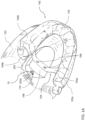
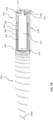
- an embodiment of an intra-oral device 10 secured within the mouth of a user The mouth of the user includes the upper jaw 120 which carries a set of teeth 122, which may be, for example, the natural teeth of the user, teeth surgically implanted in the jaw 120, or removable dentures.
- the intra-oral device 10 includes a base member 102 for securing to teeth 122 of the user, a band 104 connected to the base member 102, and a moisture sealed enclosure 106 connected to the band 104 for housing an electro-mechanical assembly 200 which provides upper airway support to the user.
- upper airway generally refers to the section of the respiratory tract that includes sections of the pharynx, such as the oropharynx and nasopharynx, and may also include the nose and nasal passages, paranasal sinuses, and portions of the larynx above the vocal cords.
- the intra-oral device 10 is depicted as securing to the teeth in the upper jaw of the user, it should be understood to one of ordinary skill in the art that the intra-oral device 10 may be similarly designed and manufactured to secure to the teeth in the lower jaw of the user.
- the base member 102 is formed from an acrylic based arcuate mold of the teeth 122 of the user.
- the base member 102 may be designed according to well accepted design standards in the medical and dental industries for intra-oral devices, such as, for example, teeth realignment devices, devices for bruxism treatment, or devices for mandibular advancement.
- the base member 102 is preferably manufactured from a hard plastic, but may also be manufactured from any other suitable material for intra-oral use, including, but not limited to, metal based materials and the like.
- the base member 102 is manufactured to match elements of the mouth of the user in both size and shape, and includes anchoring mechanisms, such as, for example, ball clasps or vacuum based tight fitting acrylic dental impression molds, for securing to the teeth 122.
- anchoring mechanisms such as, for example, ball clasps or vacuum based tight fitting acrylic dental impression molds
- the base member 102 may additionally be formed such that the mouth of the user is maintained slightly agape when the base member 102 is secured to the teeth 122, providing increased space in the oral cavity for positioning the enclosure 106 and the electro-mechanical assembly 200.
- oral cavity generally refers to the sections of the mouth that include the inside lining of the lips, the buccal mucosa, the teeth and gums, the majority of the tongue, the floor of the mouth below the tongue, the hard palate, sections of the soft palate, and the oropharynx, which generally includes the tissue of the soft palate as well as the distal portions of the tongue.
- the band 104 includes two ends, a first end 104a and a second end 104b, and extends laterally, from left to right, across the base member 102.
- the base member 102 includes two branches, a first branch 102a and a second branch 102b. Each branch extends along the arcuate perimeter of the based member 102 towards the location of respective molars in the upper jaw 120, and includes anchoring mechanisms for securing to the teeth 122 in the upper jaw 120. Each of the anchoring mechanisms is configured to secure to a respective tooth, or pair of teeth, in the upper jaw 120.
- the band 104 is secured to the base member 102 by connecting the first end 104a to the first branch 104a and connecting the second end 104b to the second branch 102b.
- the base member 102 and the band 104 may be formed from a single body, or may formed from separate bodies and connected by any suitable technique, including, but not limited to, adhesive or epoxy bonding techniques.
- the band 104 is preferably arcuate in shape, and forms an arc that protrudes upwards towards the hard palate of the user. A gap of approximately 8 millimeters is maintained between the hard palate and sections of the band 104 closest in distance to the hard palate to allow for the installation of the enclosure 106. In embodiments in which the base member 102 is secured to the teeth in the lower jaw, the arc of the band 104 protrudes upwards at a higher degree to minimize contact between the band 104 and the tongue.
- the enclosure 106 is connected to the band 104 via metallic screws 108, the heads of which are shown in FIG. 1A .
- the metallic screws 108 may also serve as electrical contact points for charging the electrical components of the electro-mechanical assembly 200 housed within the enclosure 106, without breaching the moisture seal of the enclosure 106. Although two metallic screws 108 are depicted in FIG. 1A , more than two such metallic screws may be used to secure the enclosure 106 to the band 104. Note that alternative fastening techniques for connecting the enclosure 106 the band 104 may be used, including, but not limited to, adhesive or epoxy bonding techniques.
- the space between the branches 102a and 102b may be filled with a layer or layers of material, such as, for example, hard plastic or the like.
- the enclosure 106 may be directly attached to the material layer between the branches 102a and 102b without necessitating the use of the band 104 for attaching the enclosure 106 to the base member 102.
- the enclosure 106 is preferably manufactured with an outer surface coated with or formed by a bio-compatible material appropriate for extended intra-oral use, such as for example, acrylic resins commonly used in the medical and dental industries. Furthermore, the edges of the enclosure 106 are preferably rounded and smooth to reduce discomfort, and prevent injury to tissue and muscles in the oral cavity, such as the tongue, gums, hard palate and sections of the soft palate.
- the enclosure 106 may be manufactured to match the palate of the user in both size and shape, such that the upper surface of the enclosure 106 matches the general curvature of the hard palate. Additionally, the enclosure 106 is preferably of sufficiently small volume, such that the intra-oral device 10 does not provide discomfort to the user.
- the enclosure is preferably approximately 25 millimeters in length, 15 millimeters in width, and 8 millimeters in height. Such dimensions allow the intra-oral device 10, and more particularly the enclosure 106, to rest comfortably between the hard palate and the tongue of the user, when inserted in the mouth.
- the enclosure 106 houses an electro-mechanical assembly 200 which provides upper airway support to the user, and reduces breathing obstructions, such as those induced by the onset of OSA.
- the electro-mechanical assembly 200 includes an elastic support member 202 which acts as a retractable and deployable stent for placement in the upper airway, an electro-mechanical drive arrangement 210 for retracting and deploying the elastic support member 202, a control unit 204 for actuating the electro-mechanical drive arrangement 110, and a power supply 206.
- the elastic support member 202 may be designed to be replaceable, providing the user with the option of replacing the elastic support member 202 after extended use. This serves as a form of preventative maintenance, reducing the risk of malfunction of the elastic support member 202 after extended periods of use.
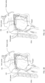
- the elastic support member 202 is moveable between two states, a retracted state ( FIGS. 1A and 3A ) and a deployed state ( FIGS. 1B, 1C and 3B ).
- the electro-mechanical drive arrangement 210 provides power and mechanical drive, based on control input from the control unit 204, to move the elastic support member 202 between the two states.
- the control unit 204 includes at least one processor 205 coupled to a storage medium 208 such as a memory or the like.
- the processor 205 is also preferably coupled to an analog to digital conversion (ADC) module 207 for receiving analog input and providing digitized output to the processor 205.
- ADC analog to digital conversion
- the processor 205 can be any number of computer processors, including, but not limited to, a microcontroller, a microprocessor, an ASIC, a DSP, and a state machine.
- Such processors include, or may be in communication with computer readable media, which stores program code or instruction sets that, when executed by the processor, cause the processor to perform actions.
- Types of computer readable media include, but are not limited to, electronic, optical, magnetic, or other storage or transmission devices capable of providing a processor with computer readable instructions.
- the length, along the longitudinal axis of the elastic support member 202, of the portions of the elastic support member 202 which protrude through the hole 110 when in the retracted state, is approximately in the range of 5-10 millimeters Furthermore, a special separation in the range of approximately 5-15 millimeters is provided between the region of contact tissue (i.e., the portion of the walls of the upper airway) and the distal end 202a when the base member 102 is secured to the mouth of the user and the elastic support member 202 is in the retracted state.
- the intra-oral device 10 when the intra-oral device 10 is initially positioned in the mouth of the user with the elastic support member 202 retracted, no portions of the elastic support member 202 make any contact with regions of tissue in the oral cavity and/or the upper airway which may stimulate the gag reflex.
- the entirety of the elastic support member 202 is preferably enclosed and retained within a casing, which is permanently and entirely retained within the enclosure 106.
- a casing will be described in further detail below with reference to non-limiting exemplary implementations of the elastic support member 202 and the electro-mechanical drive arrangement 210.
- the elastic support member 202 moves from the retracted state to the deployed state, the elastic support member 202 increases in length, and in certain embodiments increases in diameter and volume as well, resulting from the movement out of the enclosure 106 through the hole 110.
- the hole 110 is typically sealed with an elastic annular seal that allows the elastic support member 202 to move in and out of the enclosure 106 while preventing excess amounts of moisture from permeating the enclosure 106 and coming into contact with electronic and mechanical components, such as the power supply 206, the control unit 204, and components of the electro-mechanical drive arrangement 210.
- the elastic support member 202 is retracted and deployed from a separate compartment within the enclosure 106, which is fluidically-isolated from the compartment holding the electronic and mechanical components.
- the distal end 202a and/or other portions of the elastic support member 202 contact regions of tissue in the oral cavity and/or the upper airway of the user, such as the oropharynx and nasopharynx, and more specifically sections of tissue of the soft palate.
- the elastic support member 202 applies radial forces to the region of contact tissue (i.e., the walls of the upper airway) which prevents the collapse of the airway from the weight of the surrounding tissue and from the reduced atmospheric pressure in the airway.
- the elastic support member 202 when in the deployed state, maintains the integrity of the upper airway of the user and prevents the full or partial collapse of the upper airway induced by the onset of OSA or similar disorders.
- the elastic support member 202 lengthens, due to movement from the retracted state to the deployed state, the elastic support member 202 bends with the curvature of the soft palate, as illustrated in FIGS. 1B and 1C . It is also noted that the elastic support member 202 is defined to be in the deployed state when the distal end 202a and/or other portions of the elastic support member 202 make contact with the above mentioned regions of tissue, such that elastic support member 202 applies appropriate radial forces to the regions of tissue, in the oral cavity and/or the upper airway of the user.
- the length of the elastic support member 202 may continue to increase, as driven by the electro-mechanical drive arrangement 210 under actuation by the control unit 204, while in the deployed state until reaching a maximum deployed length.
- the elastic support member 202 may assume a range of lengths, between an initial deployed length and a maximum deployed length, while in the deployed state. Examples of the elastic support member 202 assuming an initial deployed length and a maximum deployed length are illustrated in FIGS. 1B and 1C , respectively.
- the example lengths of the initial deployed length and maximum deployed length as depicted in FIGS. 1B and 1C , respectively, are strictly illustrations intended to provide a better understanding of the functionality of the components of the intra-oral device 10 described herein.
- the initial deployed length may be shorter or longer than the initial deployed length illustrated in FIG. 1B
- the maximum deployed length may be shorter or longer than the maximum deployed length illustrated in FIG. 1C .
- the elastic support member 202 is defined to be in the retracted state when the distal end 202a and/or any other portions of the elastic support member 202 refrain from making contact with the region of contact tissue in the oral cavity and/or the upper airway of the user, or any other regions of tissue and/or muscles in the mouth, and/or the oral cavity, and/or the upper airway.
- the distal end 202a is spatially separated from the region of contact tissue by approximately 5-15 millimeters when in the retracted state.
- the length of the elastic support member 202 may continue to decrease from a length that promotes 5 millimeters of spatial separation between the distal end 202a and the region of contact tissue, to a length that promotes 15 millimeters of spatial separation, while being defined to be in the retracted state.
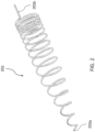
- the elastic support member 202 is formed as a helical spring which has a generally rounded edged rectangular cross-sectional shape along the majority of the length of the helical spring 202. Movement of the helical spring 202 between the retracted and deployed states is induced by rotation of the helical spring 202 about its longitudinal axis.
- the remainder of the present disclosure describes the components of the intra-oral device 10 with reference to the elastic support member 202 implemented as a helical spring.
- the elastic support member 202 may be formed as any suitable shape which can provide support and prevent collapse as mentioned above while still allowing the retraction into the enclosure 106, such as, for example, a cylinder-like structure or a plate-like structure, and that the helical spring structure of the elastic support member 202 should not limit the functionality of other components of the intra-oral device 10 to the functionality described with respect to the exemplary helical spring structure implementation.
- the helical spring 202 is formed by a wire, such as, for example, Nitinol wire, which is wound to generate the coils of the helical spring 202.
- wire such as, for example, Nitinol wire
- the term “coil” is used interchangeably with the term “loop”, and refers to individual ring shaped sections of the spring.
- the helical spring includes a proximal end 202b and the distal end 202a which is preferably formed into a rounded soft end to prevent injury to soft tissue in the oral cavity and/or upper airway when the elastic support member 202 moves between the retracted and deployed states.
- Each of the coils along a majority of the length of the helical spring has approximately equal diameter. According to a non-limiting implementation as illustrated in FIG.
- the diameter of the last few coils gradually decrease near the distal end 202a, resulting in a generally rounded conical cross-section.
- the coil closest in proximity to the distal end 202a has the smallest diameter of all of the coils of the helical spring 202.
- Such an implementation allows for helical spring 202 to thread through small openings in the oral cavity and upper airway, such as between the tongue and the soft palate.
- the helical spring 202 preferably includes approximately 10-15 coils. When in the deployed state (i.e., when the spring is at least partially relaxed), the spacing between adjacent coils is approximately 4-15 millimeters, and more preferably approximately 7-10 millimeters. Note that the spacing between pairs of adjacent coils is not necessarily uniform.
- the helical spring 202 has a variable length in the range of approximately 40-150 millimeters, and more preferably in the range of 40-120 millimeters.
- the minimum length of the helical spring 202 is the length of the spring when in the retracted sate (i.e., when the spring is fully compressed).
- the maximum deployed length of the helical spring 202 is the maximum length of the spring when in the deployed state.
- the helical spring 202 can achieve a length in the retracted state that is approximately 5-15% of the maximum deployed length.
- each coil of the helical spring 202 preferably has a variable diameter in the range of approximately 5-15 millimeters, and more preferably in the range of 5-10 millimeters.
- the minimum diameter of the helical spring 202 is the diameter of the spring when in the retracted state.
- the maximum deployed diameter of the helical spring 202 is the maximum diameter of the spring when in the deployed state.
- the helical spring 202 can achieve a diameter in the retracted state that is approximately 30% of the maximum deployed diameter.
- the helical spring 202 is compressible to a small volume as needed, preferably to a volume less than 10% of the original volume, and most preferably to a volume less than 5% of the original volume.
- the helical spring 202 When in the deployed state, the helical spring 202 allows an air passage along the longitudinal axis with a free cross-sectional area at any point along the length of the spring.
- the cross-sectional area is in the range of 20-200 square millimeters, and more preferably in the range of 40-200 square millimeters.
- the helical spring 202 is compressible in both length and diameter.
- the helical spring 202 has a variable cross-sectional area along the length of the spring.
- the helical spring 202 maintains at least 50% of the maximum cross-sectional area along the entire length of the helical spring 202 under an evenly distributed tangential pressure of at least 2068 Pa, but not more than 3447 Pa.
- drops in atmospheric pressure in the oral cavity are typically due to fluid flow, such as, for example, inhalation of air and swallowing of saliva.
- fluid flow such as, for example, inhalation of air and swallowing of saliva.
- the above preferred ranges of cross-sectional area are intended to withstand tangential pressures due to fluid flow at a rate of approximately 4 liters per sec.
- the portion of the helical spring 202 that is deployed from the enclosure 106 increases in length, when moving from the retracted state to the deployed state, at a rate in the range of approximately 0.5-20 millimeters per minute.
- the relatively slow deployment allows the nerves in the oral cavity, more specifically, at the base of the tongue, that stimulate the gag reflex sufficient time to habituate to the contact between the helical spring 202 and the tissue in the oral cavity and/or upper airway.
- a helical spring 202 having a maximum deployed length of 100 millimeters may reach the full length after an elapsed time of 5-200 minutes, with an average elapsed time to maximum deployed length of approximately 30 minutes.
- the helical spring 202 is preferably coated with a low friction material suitable for intra-oral use, such as, for example, silicone, Polytetrafluoroethylene (PTFE) or the like.
- a low friction material suitable for intra-oral use such as, for example, silicone, Polytetrafluoroethylene (PTFE) or the like.
- the low friction material coating preferably has a coating thickness in the range of approximately 50-300 microns. The low friction material coating reduces the coefficient of friction between the helical spring 202 and the region of contact tissue in the mouth of the user, lessening the risk of erosion or pressure wounds.
- the coating maintains the integrity of the helical spring 202 and allows the electro-mechanical drive arrangement 210 to retract the helical spring 202, or the user to remove the intra-oral device 10 from the mouth without debris from components of the intra-oral device 10 being maintained in the mouth of the user. Additionally, the low friction material coating decreases the rate of buildup of residue and other materials on the helical spring 202 over time.
- the electro-mechanical drive arrangement 210 provides power and mechanical drive to move the helical spring 202 between the retracted and deployed states.
- the electro-mechanical drive arrangement 210 preferably includes a retraction and deployment mechanism 216, an electric motor 212 for driving the retraction and deployment mechanism 216, and a gear 214.
- the electric motor is of sufficiently small enough size to fit inside the size of the enclosure 106 as described above.
- power supplies and devices operating on voltages of no more than 12 volts direct current (DC) are termed “low voltage”, while power supplies of at least 100 volts alternating current (AC) are defined as “mains voltage power supplies”.
- a mains voltage power supply in the United States typically supplies power in the range of 100-120 volts AC
- a mains voltage power supply in Europe typically supplies power in the range of 220-240 volts AC.
- the electric motor 212 is a direct current (DC) electric motor that receives DC voltage, preferably from the power supply 206, as input. Examples of such DC electric motors include, but are not limited to, 3-volt DC electric motors such as those produced by Marswell Engineering Ltd. of Hong Kong.
- the power supply 206 is preferably implemented as a low voltage rechargeable battery with a maximum voltage of 12 volts DC.
- the metallic screws 108 provide electrical contact points with the rechargeable power supply 206.
- a charging arrangement 302 coupled to a bedside unit 300, connected to a mains voltage power supply, may be configured to recharge the rechargeable power supply 206 via the metallic screws 108.
- a charging interface such as, for example, charging cables or other suitable electrical connections, may be used to recharge the rechargeable power supply 206.
- the power supply 206 may be a non-rechargeable power supply (i.e., a replaceable power supply), such as a disposable battery.
- the electric motor 212 drives the retraction and deployment mechanism 216 through the gear 214 that is positioned on a shaft 213 of the electric motor 212.
- electric motors provide nominally high revolutions per minute (RPM) and low torque output.
- RPM revolutions per minute
- the gear 214 converts the high RPM and low torque output from the electric motor 212 to low RPM and high torque necessary to drive the retraction and deployment mechanism 216 at the desired retraction and deployment rate.
- a torque sensor (not shown) may be placed at the output of the gear 214 to verify proper functionality of the electro-mechanical drive arrangement 210.
- FIGS. 3A-5 a non-limiting exemplary implementation of the retraction and deployment mechanism 216.
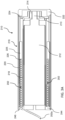
- the retraction and deployment mechanism 216 is implemented as a cylinder arrangement that drives the deployment of the helical spring 202 and houses the helical spring 202 when in the retracted state.
- FIGS. 3A and 3B show cross-sectional views of the retraction and deployment mechanism 216 with the helical spring 202 in the retracted and deployed states, respectively. For clarity of illustration, the helical spring 202 is not shown in FIGS. 4 and 5 .
- the cylinder arrangement includes a hollow inner cylinder 218, a hollow outer cylinder 220, and a release plate 240 for guiding the retraction and deployment of the helical spring 202 from the retraction and deployment mechanism 216 through the hole 110.
- the hollow inner cylinder 218 has a diameter of approximately 4.5 millimeters
- the hollow outer cylinder has a diameter of approximately 5.5 millimeters.
- the release plate 240 includes a generally hollow cylindrical section 242 having an interior surface defining an interior volume, and a flange 244 at the distal end of the release plate 240.
- the release plate 240 also includes a generally curved slot 246 extending partially through the flange 244, for allowing passage of the helical spring 202 in and out of the cylinder arrangement during movement between the retracted and deployed states.
- Each of the cylinders 218 and 220 has a respective interior and exterior surface, with each of the interior surfaces defining a respective interior volume.
- the hollow cylindrical section 242 of the release plate 240 is positioned within the interior volume of the hollow inner cylinder 218.
- the electric motor 212 is positioned within the interior volume defined by the interior surface of the hollow cylindrical section 242 of the release plate 240.
- the shaft 213 passes through an opening in the proximal end of the release plate 240. Accordingly, in such an implementation, the electric motor 212 and corresponding components thereof are considered part of the retraction and deployment mechanism 216.
- the hollow inner cylinder 218 is positioned within the interior volume defined by the interior surface of the hollow outer cylinder 220.
- an annular space 226 is provided between the exterior surface of the hollow inner cylinder 218 and the interior surface of the hollow outer cylinder 220.
- the annular space 226 extends along a portion of the length of the hollow inner cylinder 218 between the distal end of the cylinder arrangement and a flange 219 of the hollow inner cylinder 218. It is preferred that the length of the helical spring 202, when maximally compressed, is longer than the length for which the annular space 226 extends allowing protrusion of the distal end 202a as described above.
- the helical spring 202 When in the retracted state, the helical spring 202 is wound around the exterior surface of the inner hollow cylinder 218 and compressed and entirely housed, except for the distal end 202a and portions of the elastic support member 202 proximate to the distal end 202a, in the annular space 226 between the exterior surface of the hollow inner cylinder 218 and the interior surface of the hollow outer cylinder 220.
- the flange 244 provides a cover to the opening of the annular space 226 in the distal end of the cylinder arrangement, preventing the helical spring 202 from escaping entirely out of the annular space 226.
- a portion of the curved slot 246 is coupled to the annular space 226, providing a pathway for the helical spring 202 to move into and out of the cylinder arrangement, during movement between the retracted and deployed states.
- the flange 219 extends over approximately the last 1 ⁇ 4 of the length of the hollow inner cylinder 218 towards the proximal end of the cylinder arrangement.
- the proximal end 202b of the helical spring 202 is dimensioned and oriented to prevent the distal end 202 from passing through the curved slot 246, preventing the helical spring 202 from fully separating from the cylinder arrangement.
- the proximal end 202b of the helical spring 202 is permanently retained within the annular space 226 during movement between the retracted and deployed states.
- the proximal end 202b is dimensioned and oriented to be parallel to the longitudinal axis of the helical spring 202.
- the retraction and deployment mechanism 216 when implemented as such a cylinder arrangement, further acts as the casing, for enclosing and retaining almost the entirety of the helical spring 202, which is permanently and entirely retained within the enclosure 106, as briefly discussed above.
- the cylinder arrangement may further include a hollow intermediate cylinder 221 having an interior and an exterior surface, with the interior surface defining an interior volume.
- the hollow inner cylinder 218 is positioned within the interior volume defined by the interior surface of the hollow intermediate cylinder 221, and the hollow intermediate cylinder 221 is positioned within the interior volume defined by the interior surface of the hollow outer cylinder 220.
- the hollow intermediate cylinder 221 includes two sections having two differing internal diameters, namely a main section 223 having a first internal diameter, and an indented section 225 having a second internal diameter.
- the first internal diameter is larger than the second internal diameter.
- the location within the hollow intermediate cylinder 221 in which the change in internal diameter occurs forms a step 227 defining the farthest point the proximal end 202b of the helical spring 202 can be positioned in the annular space 226.
- the use of the hollow intermediate cylinder 221 results in a more compressed helical spring 202 in the retracted state.
- a cylinder cover 222 connects to, and covers, both of the cylinders 218 and 210 at the proximal ends of the cylinders 218 and 220, fixedly maintaining the electric motor 212 within the release plate 240, the hollow cylindrical section 242 of the release plate 240 within the hollow inner cylinder 218, and the hollow inner cylinder 218 within the hollow outer cylinder 220.
- the cylinder cover 222 also connects to, and covers, the gear 214 via a gear cover 224. Additional fasteners may be used to fortify the fixedly nested placement of the electric motor 212, the hollow inner cylinder 218, and the hollow outer cylinder 220.
- the annular space 226 and the curved slot 246 provide a path for the passage of the helical spring 202 in and out of the cylinder arrangement during movement between the retracted and deployed states. Accordingly, rotation of the cylinders 218 and 220 causes the helical spring 202 to lengthen or shorten and the distal end 202a to extend out of, or retreat into, the cylinder arrangement through the curved slot 246 via the hole 110, when moving between the retraced state and the deployed state.
- Movement from the retracted state to the deployed state is caused by actuation of the electric motor 212, by the control unit 204, which causes the cylinder arrangement to rotate in a clockwise direction of rotation (when viewed from the proximal end of the enclosure 106 ).
- Clockwise rotation of the cylinder arrangement causes the helical spring 202 to rotate clockwise about the longitudinal axis, forcing the distal end 202a through the curved slot 246 and out of the hole 110, thereby increasing the length of the helical spring 202 from the initial compressed length ( FIG. 3A ), towards the initial deployed length ( FIG. 1B ), and ultimately towards the maximum deployed length ( FIG. 1C ) of the deployed state.
- the helical spring 202 As the distal end 202a is forced through the curved slot 246 and out of the hole 110, the helical spring 202 unwinds from around the exterior surface of the hollow inner cylinder 218.
- the clockwise rotation allows the helical spring 202 to advance (i.e., lengthen) under its own force, without the need to generate axial forces to push the helical spring 202 into the oral cavity and/or the upper airway.
- actuation of the electric motor 212 causes the cylinder arrangement to rotate in a counter clockwise direction of rotation.
- Counter clockwise rotation of the cylinder arrangement causes the helical spring 202 to rotate counter clockwise about the longitudinal axis, pulling the distal end 202a towards the hole 110 and the curved slot 246, and decreasing the length of the helical spring 202 from the deployed length, towards the fully compressed and initial length of the retracted state ( FIG. 3A ).
- counter clockwise rotation of the helical spring 202 causes the helical spring 202 to wind around the exterior surface of the hollow inner cylinder 218, within the annular space 226.
- the electro-mechanical drive arrangement 210 is configured to continually rotate the helical spring 202, clockwise, subsequent to the helical spring 202 reaching the deployed state, and ultimately subsequent to the helical spring 202 reaching the maximum deployed length.
- the rate of rotation of the helical spring 202 in the clockwise direction of rotation subsequent to reaching the maximum deployed length is preferably in the range of 0.1-1 rotations per minute. Accordingly, once fully deployed, the helical spring 202 is moved, via rotation, against different contact points of tissue inside the oral cavity and/or the upper airway, in a rhythmic type motion, or other type of motion which the electric motor 212 can be programmed to execute.
- the distal end 202a constantly changes the regions of contact between the helical spring 202 and the tissue in oral cavity and/or the upper airway. This reduces the risk of the development of pressure sores due to increased pressure on the region of contact tissue and lower than atmospheric pressure in the upper airway due to the inhalation of air by the user. Additionally, such continual rotation and movement increases the efficacy of the intra-oral device 10 by repositioning the elastic support member 202 to contact the region of contact tissue in the event that the elastic support member 202 is displaced by the tongue or other muscles in the oral cavity.
- control unit 204 actuates the electric motor 212 to drive the retraction and deployment mechanism 216.
- the actuation by the control unit 204 may be based on input received from a sensor arrangement 230 which may include a variety of sensors for providing information and data relevant to the user, including, but not limited to, air pressure sensors, air flow sensors, temperature sensors, optical heart rate sensors, optical pulse oximetry sensors, electromyography (EMG) sensors, force sensors, audio sensors, motion sensors, and humidity sensors.
- sensors may be implemented as transducers, and are preferably in fluid flow communication with the air in the oral cavity of the user, or suitably installed within the enclosure 106 so as to properly generate associated electrical signals.
- Such sensors may be used to gather data and assess the physiological state of the user, by, for example, determining parameters for evaluating, such as, for example, respiration status, onset of apnea and hypopnea, blood oxygenation, heart rate, gross body motions, bruxism, snoring and sleep/wake status.
- the sensors of the sensor arrangement 230 provide electrical signals to the control unit 204, which are preferably digitized by the ADC 207 before being processed by the processor 205.
- the processor 205 preferably runs real-time program code, such as, for example, firmware, which allows for real-time operation of the components of the intra-oral device 10. Accordingly, the control unit 204 may actuate the electro-mechanical drive arrangement 210 to deploy the helical spring 202 at a prescribed rate of deployment, retract the helical spring 202 at a prescribed rate of retraction, and continually rotate the helical spring 202 at a prescribed rate subsequent to movement to the deployed state.
- data collected from the sensors of the sensors arrangement 230 may be stored in the storage medium 208, or another memory, such as, for example, a non-volatile memory, coupled to the processor 205, for analysis.
- the same sensor data may be used to modulate the functioning of the real-time program code, in ways that may increase the efficacy of the treatment. For example, such modulation may result in an increase in the length of the deployed elastic support member 202 if apneic events are still detected while the elastic support member 202 is already deployed, or may prevent the deployment of the elastic support member 202 if the sensor data is interpreted as indicating that the user is still awake. Additional conditions for such modulations will be presented in further detail in subsequent sections of the present disclosure.
- the sensor arrangement 230 may also include an integrity sensor for measuring the integrity of the elastic support member 202. Accordingly, if the integrity of the elastic support member 202 is determined to be compromised, due to malfunction or damage, based on received signals from the integrity sensor, the control unit 204 may be configured to refrain from actuating the electro-mechanical drive arrangement 210 to move the elastic support member 202, to either of the deployed or retracted states to avoid causing damage to the tissue in the oral cavity and/or upper airway, and to avoid further damaging the intraoral device 10.
- the intra-oral device 10 may be removably coupled to a bedside unit 300. connected to a mains voltage power supply that includes a charging arrangement 302 for recharging the rechargeable power supply 206 via the metallic screws 108.
- the removable coupling of the intra-oral device 10 to the bedside unit 300 may be via receiving interface (not shown) in the bedside unit, such as, for example, a docking station.
- the intra-oral device 10 may be configured, via the control unit 204, to deploy the helical spring 202 to the maximum deployed length when the intra-oral device 10 is docked in the docking station of the bedside unit 300. Such deployment allows for manual or automatic cleaning and disinfection of the helical spring 202 during docking. Additionally, integrity validation of the components and sub-components of the intra-oral device 10 may be performed during docking. Upon completion of cleaning, disinfection, and integrity verification, the helical spring 202 moves to the retracted state.
- the bedside unit 300 preferably includes a control unit 304 and a user interface (UI) 312.
- the control unit 304 includes at least one processor 305 coupled to a storage medium 308 such as a memory or the like.
- the processor 305 can be any number of computer processors, including, but not limited to, a microcontroller, a microprocessor, an ASIC, a DSP, and a state machine.
- Such processors include, or may be in communication with computer readable media, which stores program code or instruction sets that, when executed by the processor, cause the processor to perform actions.
- Types of computer readable media include, but are not limited to, electronic, optical, magnetic, or other storage or transmission devices capable of providing a processor with computer readable instructions.
- both of the control units 204 and 304 are coupled to respective communication units, 209 and 309, allowing for the intra-oral device 10 to transmit recorded physiological data and parameters recorded via the sensor arrangement 230 to the bedside unit 300.
- the communication between the communication units 209 and 309 may be via any suitable short range communication paradigm known in the art.
- the control unit 204 is configured to actuate the communication unit 209 to transmit such data to the communication unit 309.
- the data received by the communication unit 309 may be subsequently stored in the storage medium 308, or another memory, such as, for example, a non-volatile memory, coupled to the processor 305, for analysis.
- control unit 304 may be configured to actuate, via instructions transmitted by the communication unit 309 and received by the communication unit 209, the electro-mechanical drive arrangement 210 to move the helical spring 202 between the retracted and deployed states or any position in between these states
- the UI 312 is permanently coupled to the control unit 304, and may also couple to the control unit 204 when the intra-oral device 10 is docked with the bedside unit 300. As such, the UI 312 allows the user to retrieve data stored in a memory of the intra-oral device 10 or the bedside unit 300, such as, for example, the storage mediums 208 and 308.
- the bedside unit 300 may further include input and output ports for connecting the bedside unit 300 to a computing device, such as, for example, a laptop or desktop computer, or a personal communication computing device, such as, for example, a tablet or smartphone.
- the UI 312 may be implemented as any suitable interface platform, such as, for example, a touchscreen or the like.
- the UI 312 also allows the user to select different modes of operation of the intra-oral device 10 when in use.
- the deployment modes as will be described herein represent non-limiting examples of possible deployment scenarios of the intra-oral device 10, and that other deployment scenarios of the intra-oral device 10 may be possible.
- Time Mode One non-limiting exemplary deployment mode is hereinafter referred to as "Timed Mode"
- the control unit 204 actuates the electro-mechanical drive arrangement 210 to begin moving the helical spring 202 from the retracted state to the deployed state after a predetermined period of time elapses from activation of the intra-oral device 10.
- the predetermined period of time is preferably set by the user via the UI 312 when the intra-oral device 10 is docked with the bedside unit 300. Accordingly, the intra-oral device 10 becomes active, or is activated, upon decoupling of the intra-oral device 10 from the bedside unit 300.
- the user preferably sets the predetermined time to allow enough time for the user to fall asleep before movement of the helical spring 202 begins.
- the user secures the intra-oral device 10 to the mouth with the helical spring 202 in the retracted state, via the base member 102, and falls asleep.
- the helical spring 202 moves from the retracted state to the deployed state.
- Sleep Mode the control unit 204 analyzes received signals from the sensor arrangement 230, via the ADC module 207 and the processor 205 as discussed above. Such signals may provide an indication of the presence of one or more physiological parameters gathered from within the oral cavity, including, but not limited to, respiration airflow, temperature, humidity, heart rate, oximetry and EMG of the tongue or other muscles in the oral cavity. The analysis of the received signals by the control unit 204 allows the control unit 204 to make a determination if the user is asleep or awake.
- control unit 204 Upon the determination (i.e., detection), by the control unit 204, of the onset of sleep or any other predetermined sleep stage or event, the control unit 204 actuates the electro-mechanical drive arrangement 210 to begin moving the helical spring 202 from the retracted state to the deployed state.
- Apnea Mode Similar to as in Sleep Mode, in Apnea Mode, the control unit 204 analyzes received signals from the sensor arrangement 230, via the ADC module 207 and the processor 205 as discussed above. Such signals may provide an indication as to whether the user is experiencing respiratory events such as snoring, hypopneas or apneas. The analysis of the received signals by the control unit 204 allows the control unit 204 to make a determination if the user is experiencing such respiratory events.
- control unit 204 Upon the determination (i.e., detection), by the control unit 204, of the onset of such respiratory events, the control unit 204 actuates the electro-mechanical drive arrangement 210 to begin moving the helical spring 202 from the retracted state to the deployed state.
- Timed Mode, Sleep Mode, and Apnea Mode share the common condition that the intra-oral device 10 is positioned in the mouth of the user, via the base member 102, with the helical spring 202 in the retracted state. Furthermore, in the above described modes, the movement of the helical spring 202 from the retracted state to the deployed state occurs subsequent to the user falling asleep. As such, insertion of the intra-oral device 10 in the mouth with the helical spring 202 in the retracted state alleviates the gag reflex upon insertion, and reduces the negative psychological effects associated with insertion of the intra-oral device 10 in the mouth.
- the electro-mechanical drive arrangement 210 may be configured to continually rotate the helical spring 202 to reduce the risk of the development of pressure sores in the oral cavity and/or the upper airway. Additionally, the control unit 204 may be configured to actuate the electro-mechanical drive arrangement 210 to adjust the length of the helical spring 202, while maintaining the helical spring 202 in the deployed state, based on the severity of respiratory disturbances measured from signals received from the sensor arrangement 230.
- control unit 204 may actuate the electro-mechanical drive arrangement 210 to lengthen the helical spring 202 when more respiratory disturbances are measured, and shorten the helical spring 202 when fewer respiratory disturbances are measured.
- control unit 204 may actuate the electro-mechanical drive arrangement 210 to vary the length of the helical spring 202 towards the maximum deployed length when more respiratory disturbances are measured, and towards the initial deployed length when fewer respiratory disturbances are measured.
- the helical spring 202 moves from the deployed state to the retracted state. Such movement may be accomplished in various ways.
- several different retraction modes are presented herein. As should be understood, the retraction modes as will be described herein represent non-limiting examples of possible retraction scenarios of the intra-oral device 10, and that other retraction scenarios of the intra-oral device 10 may be possible.
- One retraction mode follows a methodology similar to that of Timed Mode, described above.
- a time may be set, via the UI 312 when the intra-oral device 10 is docked with the bedside unit 300, at which the control unit 204 actuates the electro-mechanical drive arrangement 210 to move the helical spring 202 from the deployed state to the retracted state.
- the intra-oral device 10 may receive the time as input, via the communication unit 209, from an external alarm clock, or via an alarm clock embedded as part of the bedside unit 300.
- the intra-oral device 10 may receive the time as input, via the communication unit 209 or the control unit 204, from a wireless or wired remote control.
- control unit 204 actuates the electro-mechanical drive arrangement 210 to move the helical spring 202 from the deployed state to the retracted state slightly before the set time, allowing enough time for retraction before the user awakens. Accordingly, upon waking from the sleep, the user may remove the intra-oral device 10 from the mouth with the helical spring 202 mostly or fully retracted.
- Another retraction mode follows a methodology similar to that of Sleep Mode and Apnea Mode, described above.
- the control unit 204 analyzes received signals from the sensor arrangement 230, via the ADC module 207 and the processor 205 as discussed above. Such signals may provide an indication as to whether the user is experiencing signs of waking, such as, for example, EMG, increased heart rate variability, and increased body motion.
- the analysis of the received signals by the control unit 204 allows the control unit 204 to make a determination if the user is experiencing such signs of waking.
- the control unit 204 actuates the electro-mechanical drive arrangement 210 to begin moving the helical spring 202 from the deployed state to the retracted state.
- control unit 204 may analyze received signals from the sensor arrangement 230 over a period of several nights, in order to make a determination or prediction of the time of waking of the user. Such a prediction may be made by implementing, via the processor 205, algorithms such as, for example, supervised learning algorithms, unsupervised learning algorithms, and pattern recognition algorithms. Accordingly, the control unit 204 is able to actuate the electro-mechanical drive arrangement 210 to begin moving the helical spring 202 from the deployed state to the retracted state at the predicted time of waking.
- the above described retraction modes may be operatively used with any of the above mentioned deployment modes (e.g., Timed Mode, Sleep Mode, and Apnea Mode). It is noted that in addition to the retraction modes described above, the user may remove the intra-oral device 10 from the mouth when the helical spring 202 is in the deployed state.
- the shape of the helical spring 202, as well as the material used to form the helical spring 202, allows the helical spring 202 to be deformed into a generally straight wire when the intra-oral device 10 is removed from the mouth when the helical spring 202 is in the deployed state.
- the intra-oral device 10 as described thus far has pertained to all of the components of the electro-mechanical assembly 200 housed within the enclosure 106
- other embodiments are possible in which several of the components of the electro-mechanical assembly 200 are positioned outside of the enclosure 106, and outside of the mouth of the user.
- such embodiments may include positioning some of the sensors of the sensor arrangement 230 outside of the mouth of the user.
- actuation of the electro-mechanical drive arrangement 210 may be provided by a control unit external to the mouth of the user, such as, for example, the control unit 304 of the bedside unit 300.
- mechanical components of the electro-mechanical drive arrangement 210 may be positioned outside of the mouth of the user as well.
- the components located outside of the mouth of the user are preferably electrically and/or mechanically coupled to the components located within the enclosure 106.
Landscapes
- Health & Medical Sciences (AREA)
- Life Sciences & Earth Sciences (AREA)
- Animal Behavior & Ethology (AREA)
- Veterinary Medicine (AREA)
- Public Health (AREA)
- General Health & Medical Sciences (AREA)
- Biomedical Technology (AREA)
- Heart & Thoracic Surgery (AREA)
- Engineering & Computer Science (AREA)
- Otolaryngology (AREA)
- Vascular Medicine (AREA)
- Orthopedic Medicine & Surgery (AREA)
- Nursing (AREA)
- Pulmonology (AREA)
- Physics & Mathematics (AREA)
- Oral & Maxillofacial Surgery (AREA)
- Dentistry (AREA)
- Epidemiology (AREA)
- Biophysics (AREA)
- Pathology (AREA)
- Surgery (AREA)
- Molecular Biology (AREA)
- Medical Informatics (AREA)
- Orthopedics, Nursing, And Contraception (AREA)
- Accommodation For Nursing Or Treatment Tables (AREA)
Claims (16)
- Vorrichtung (10) zum Reduzieren von Atembehinderungen eines Benutzers, umfassend:ein Basiselement (102) zum lösbaren Koppeln mit dem Ober- oder Unterkiefer (120) des Benutzers;ein elastisches Stützelement (202), das wirksam mit dem Basiselement (102) gekoppelt ist, wobei das elastische Stützelement (202) mindestens eine Kontaktfläche zum Kontaktieren mindestens eines Gewebebereichs aufweist, wobei das elastische Stützelement (202) zwischen einem eingezogenen Zustand, in dem kein Teil des elastischen Stützelements (202) Gewebebereichen der Mundhöhle und/oder der oberen Atemwege kontaktiert, so dass den Übelkeitsreflex stimulieren könnte, und einem ausgezogenen Zustand, in dem zumindest ein Teil des elastischen Stützelement (202) so verlängert ist, dass das distale Ende (202a) und/oder andere Teile des elastischen Stützelements (202) Gewebebereiche der Mundhöhle und/oder der oberen Atemwege des Benutzers kontaktieren, so dass die Unversehrtheit der oberen Atemwege des Benutzers aufrechterhalten wird und ein Gesamt- oder Teilabsinken der oberen Atemwege verhindert wird, bewegbar ist;eine elektromechanische Antriebsanordnung (210) in mechanischer Antriebsbeziehung mit dem elastischen Stützelement (202); Undeine Steuereinheit (204), die der elektromechanischen Antriebsanordnung (210) zugeordnet ist, wobei die Steuereinheit (204) dazu konfiguriert ist, die elektromechanische Antriebsanordnung (210) zu betätigen, um das elastische Stützelement (202) zwischen dem eingezogenen Zustand und dem ausgefahrenen Zustand zu bewegen,wobei die Bewegungsgeschwindigkeit zumindest des Teils des elastischen Stützelements während der Bewegung aus dem eingezogenen Zustand in den ausgezogenen Zustand im Bereich von 0,5 bis 20 Millimeter pro Minute liegt.
- Vorrichtung (10) nach Anspruch 1, wobei, wenn das elastische Stützelement (202) im eingezogenen Zustand ist, das elastische Stützelement (202) ein Anfangsvolumen einnimmt und, wenn das elastische Stützelement (202) im ausgezogenen Zustand ist, das elastische Stützelement (202) so betreibbar ist, dass es sich in einem Volumenbereich zwischen einem ausgezogenen Anfangsvolumen und einem maximal ausgezogenen Volumen befindet, wobei das Anfangsvolumen ungefähr weniger als 10% des maximal ausgezogenen Volumens beträgt.
- Vorrichtung (10) nach Anspruch 1, wobei, wenn das elastische Stützelement (202) im eingezogenen Zustand ist, das elastische Stützelement (202) eine Anfangslänge einnimmt und, wenn das elastische Stützelement (202) im ausgezogenen Zustand ist, das elastische Stützelement (202) so betreibbar ist, dass es innerhalb eines Längenbereichs zwischen einer ausgezogenen Anfangslänge und einer maximal ausgezogenen Länge liegt.
- Vorrichtung (10) nach Anspruch 1, wobei, wenn sich das elastische Stützelement (202) im eingezogenen Zustand befindet, im Wesentlichen der größte Teil des elastischen Stützelements in einem komprimierten Zustand im Mund des Benutzers gehalten wird.
- Vorrichtung (10) nach Anspruch 1, wobei die Bewegung zwischen dem eingezogenen Zustand und dem ausgezogenen Zustand durch die Drehung des elastischen Stützelements (202) um die Längsachse des elastischen Stützelements (202) bewirkt wird.
- Vorrichtung (10) nach Anspruch 1, wobei das elastische Stützelement (202) eine Schraubenfeder (202) umfasst.
- Vorrichtung (10) nach Anspruch 1, wobei der mindestens eine Gewebebereich eine Mehrzahl von Gewebebereichen umfasst und bei Bewegung des elastischen Stützelements (202) in den ausgezogenen Zustand das elastische Stützelement (202) wirksam zur Aufrechterhaltung einer kontinuierlichen Bewegung ist, um die mindestens eine Kontaktfläche (202a) neu zu positionieren, um einen beliebigen der Mehrzahl von Gewebebereichen zu kontaktieren.
- Vorrichtung (10) nach Anspruch 1, wobei die elektromechanische Antriebsanordnung (210) eine Zylinderanordnung (216) umfasst, die einen Innenzylinder (218) mit einer Außenfläche und einen hohlen Außenzylinder (220) mit einer eine Innenfläche definierenden Innenvolumen umfasst, wobei mindestens ein Teil des Innenzylinders (218) innerhalb des Innenvolumens des hohlen Außenzylinders (220) so positioniert ist, dass ein ringförmiges Volumen zwischen der Außenfläche des Innenzylinders und der Innenfläche des hohlen Außenzylinders definiert ist.
- Vorrichtung (10) nach Anspruch 8, wobei im Wesentlichen der Großteil des elastischen Stützelements (202) innerhalb des ringförmigen Volumens gehalten wird, wenn sich das elastische Stützelement in dem eingezogenen Zustand befindet.
- Vorrichtung (10) nach Anspruch 1, wobei das Basiselement (102) eine im Wesentlichen bogenförmige Umfangsfläche umfasst, die erste und zweite Abschnitte (102a, 102b) umfasst.
- Vorrichtung nach Anspruch 10, wobei das Basiselement (102) ferner einen Streifen (104) umfasst, der mit ersten und zweiten Enden (104a, 104b) versehen ist, wobei das erste Ende (104a) fest mit dem ersten Abschnitt (104a) gekoppelt ist. 102a) und das zweite Ende (104b) fest mit dem zweiten Abschnitt (102b) gekoppelt ist, so dass sich der Streifen (104) seitlich quer über das Basiselement (102) erstreckt, und das elastische Stützelement (202) fest mit zumindest einem Teil des Streifens (104) gekoppelt ist.
- Vorrichtung (10) nach Anspruch 1, wobei der Gewebebereich zumindest einen Teil des Pharynx umfasst.
- Vorrichtung (10) nach Anspruch 1, wobei, wenn das elastische Stützelement (202) im ausgezogenen Zustand ist, das elastische Stützelement (202) ein Kraftprofil mit einer Radialkraftkomponente an den Gewebebereich verleiht.
- Vorrichtung (10) nach Anspruch 1, wobei das Basiselement (102) eine Mehrzahl von Verankerungselementen umfasst, wobei jedes jeweilige Verankerungselement dazu ausgebildet ist, entfernbar an einem jeweiligen Zahn oder Paar von Zähnen (122) des Benutzers befestigt zu werden.
- Vorrichtung (10) nach Anspruch 14, wobei jedes der Verankerungselemente einen Abdruck des jeweiligen Zahns oder Paar von Zähnen (122) umfasst.
- Vorrichtung nach Anspruch 1, ferner umfassend eine Sensoranordnung (230) mit einem oder mehreren Sensoren, die der Steuereinheit (204) zugeordnet sind und dazu ausgebildet sind, Daten zu sammeln und Eingaben an die Steuereinheit (204) bereitzustellen, welche ein Atmungsereignis während des Schlafs anzeigen, und wobei die Steuereinheit (204) ferner dazu konfiguriert ist, die elektromechanische Antriebsanordnung (210) zu betätigen, um das elastische Stützelement (202) in Reaktion auf das Erfassen eines Atmungsereignis basierend auf von dem/den Sensor(en) empfangenen Eingaben aus dem eingezogenen Zustand in den ausgezogenen Zustand zu bewegen.
Applications Claiming Priority (2)
| Application Number | Priority Date | Filing Date | Title |
|---|---|---|---|
| US201562141289P | 2015-04-01 | 2015-04-01 | |
| PCT/IL2016/050327 WO2016157174A1 (en) | 2015-04-01 | 2016-03-27 | Intra-oral device for upper airway support |
Publications (3)
| Publication Number | Publication Date |
|---|---|
| EP3277229A1 EP3277229A1 (de) | 2018-02-07 |
| EP3277229A4 EP3277229A4 (de) | 2018-12-05 |
| EP3277229B1 true EP3277229B1 (de) | 2023-05-10 |
Family
ID=57004017
Family Applications (1)
| Application Number | Title | Priority Date | Filing Date |
|---|---|---|---|
| EP16771531.7A Active EP3277229B1 (de) | 2015-04-01 | 2016-03-27 | Intraorale vorrichtung zur unterstützung der oberen atemwege |
Country Status (9)
| Country | Link |
|---|---|
| US (1) | US10219935B2 (de) |
| EP (1) | EP3277229B1 (de) |
| JP (1) | JP6743039B2 (de) |
| CN (1) | CN107360712B (de) |
| AU (1) | AU2016242282B2 (de) |
| ES (1) | ES2952133T3 (de) |
| IL (1) | IL254208B (de) |
| RU (1) | RU2706505C2 (de) |
| WO (1) | WO2016157174A1 (de) |
Families Citing this family (9)
| Publication number | Priority date | Publication date | Assignee | Title |
|---|---|---|---|---|
| US12083037B2 (en) | 2016-12-06 | 2024-09-10 | Koninklijke Philips N.V. | Mandibular advancement device and method of adjusting a dimension of a coupling assembly of a mandibular advancement device |
| CN106726044B (zh) * | 2016-12-26 | 2019-04-16 | 上海交通大学医学院附属第九人民医院 | 开口器 |
| CN106730271A (zh) * | 2016-12-26 | 2017-05-31 | 上海交通大学医学院附属第九人民医院 | 开口器 |
| WO2018160670A1 (en) * | 2017-02-28 | 2018-09-07 | Case Western Reserve University | Systems and methods for obstructive sleep apnea detection and monitoring |
| US11045348B2 (en) * | 2018-05-08 | 2021-06-29 | Archis Health Investments LLC | Apparatus for mandibular advancement of an oral appliance |
| US20200330261A1 (en) * | 2019-04-19 | 2020-10-22 | John Joseph Anderson Jones | System and method for treating bruxism |
| CN112245078B (zh) * | 2020-05-21 | 2023-02-28 | 番禺得意精密电子工业有限公司 | 用于改善睡眠呼吸阻塞的装置 |
| GB2598306A (en) * | 2020-08-24 | 2022-03-02 | Stainsby Ryan | A dental device |
| US12403033B2 (en) | 2023-04-21 | 2025-09-02 | Achaemenid, Llc | Oral appliance for the treatment of sleep apnea |
Family Cites Families (25)
| Publication number | Priority date | Publication date | Assignee | Title |
|---|---|---|---|---|
| US4669459A (en) * | 1985-11-29 | 1987-06-02 | Spiewak Martin H | Anti-snoring device |
| US6090100A (en) * | 1992-10-01 | 2000-07-18 | Chiron Technolas Gmbh Ophthalmologische Systeme | Excimer laser system for correction of vision with reduced thermal effects |
| US6051009A (en) * | 1996-02-07 | 2000-04-18 | Hellenkamp; Johann F. | Automatic surgical device for cutting a cornea and a cutting blade assembly and control assembly |
| US5915385A (en) | 1997-04-02 | 1999-06-29 | Hakimi; Farhad | Snore and stress relieving device |
| US6344040B1 (en) * | 1999-03-11 | 2002-02-05 | Intralase Corporation | Device and method for removing gas and debris during the photodisruption of stromal tissue |
| US6453905B1 (en) * | 1999-09-17 | 2002-09-24 | Pi Medical, Inc. | Multi-component snoring treatment |
| EP1487368B1 (de) * | 2002-03-23 | 2007-06-27 | Intralase Corp. | System für die verbesserte materialverarbeitung mit einem laserstrahl |
| US7073505B2 (en) * | 2002-09-06 | 2006-07-11 | Apneon, Inc. | Systems and methods for moving and/or restraining tissue in the oral cavity |
| US7351241B2 (en) * | 2003-06-02 | 2008-04-01 | Carl Zeiss Meditec Ag | Method and apparatus for precision working of material |
| US7882842B2 (en) | 2004-09-21 | 2011-02-08 | Pavad Medical, Inc. | Airway implant sensors and methods of making and using the same |
| US7909037B2 (en) * | 2006-04-20 | 2011-03-22 | Pavad Medical | Tethered airway implants and methods of using the same |
| US8857439B2 (en) | 2006-06-19 | 2014-10-14 | Insono Therapeutics, Inc. | Variable automated tissue retention system |
| US8685006B2 (en) * | 2006-11-10 | 2014-04-01 | Carl Zeiss Meditec Ag | Treatment apparatus for surgical correction of defective eyesight, method of generating control data therefore, and method for surgical correction of defective eyesight |
| JP2009034384A (ja) * | 2007-08-02 | 2009-02-19 | Ist Corp | 閉塞型睡眠時無呼吸症候群解消器 |
| JP5474952B2 (ja) * | 2008-06-20 | 2014-04-16 | ウェイブライト ゲーエムベーハー | 集束レーザ照射による組織片削り出し機器 |
| WO2010040026A1 (en) * | 2008-10-02 | 2010-04-08 | Lumen Devices Llc | A palate retainer with attached nasopharyngeal airway extender for use in the treatment of obstructive sleep apnea |
| EP2181678A1 (de) * | 2008-11-04 | 2010-05-05 | T-Products B.V. | Oralorthese zur Reduktion von Schnarch- und Schlafapnoe-Symptomen |
| WO2010068493A1 (en) * | 2008-11-25 | 2010-06-17 | Lumen Devices Llc | Devices, systems and methods for the treatment of sleep apnea |
| US8555891B2 (en) | 2009-02-18 | 2013-10-15 | Medtronic Xomed, Inc. | Implant system for controlling airway passage |
| WO2010096573A1 (en) * | 2009-02-18 | 2010-08-26 | Pavad Medical, Inc. | Implant system for controlling airway passage |
| JP2013106811A (ja) * | 2011-11-21 | 2013-06-06 | 尚 ▲高▼野 | 軟口蓋安定器 |
| RU117803U1 (ru) * | 2011-12-26 | 2012-07-10 | Вадим Александрович Луганский | Внутриротовой терапевтический аппарат луганского |
| RU117088U1 (ru) * | 2011-12-26 | 2012-06-20 | Вадим Александрович Луганский | Внутриротовой терапевтический аппарат луганского |
| US20140135868A1 (en) | 2012-11-09 | 2014-05-15 | Jacob Bashyam Bashyam | Non-invasive intraoral electrical stimulator system and method for treatment of obstructive sleep apnea (osa) |
| US20160022473A1 (en) | 2014-07-23 | 2016-01-28 | Michael Winters | Intra-oral device for manipulating the musculus uvulae and uvula |
-
2016
- 2016-03-27 EP EP16771531.7A patent/EP3277229B1/de active Active
- 2016-03-27 JP JP2017545683A patent/JP6743039B2/ja active Active
- 2016-03-27 CN CN201680019253.0A patent/CN107360712B/zh active Active
- 2016-03-27 RU RU2017130589A patent/RU2706505C2/ru active
- 2016-03-27 US US15/562,419 patent/US10219935B2/en active Active
- 2016-03-27 AU AU2016242282A patent/AU2016242282B2/en active Active
- 2016-03-27 WO PCT/IL2016/050327 patent/WO2016157174A1/en not_active Ceased
- 2016-03-27 ES ES16771531T patent/ES2952133T3/es active Active
-
2017
- 2017-08-29 IL IL254208A patent/IL254208B/en active IP Right Grant
Also Published As
| Publication number | Publication date |
|---|---|
| US10219935B2 (en) | 2019-03-05 |
| CN107360712A (zh) | 2017-11-17 |
| WO2016157174A1 (en) | 2016-10-06 |
| AU2016242282B2 (en) | 2019-12-05 |
| RU2706505C2 (ru) | 2019-11-19 |
| AU2016242282A1 (en) | 2017-09-21 |
| RU2017130589A (ru) | 2019-05-06 |
| US20180125701A1 (en) | 2018-05-10 |
| CN107360712B (zh) | 2020-11-10 |
| JP2018512903A (ja) | 2018-05-24 |
| EP3277229A4 (de) | 2018-12-05 |
| IL254208A0 (en) | 2017-10-31 |
| IL254208B (en) | 2020-02-27 |
| JP6743039B2 (ja) | 2020-08-19 |
| ES2952133T3 (es) | 2023-10-27 |
| EP3277229A1 (de) | 2018-02-07 |
| RU2017130589A3 (de) | 2019-05-06 |
| HK1245062A1 (zh) | 2018-08-24 |
Similar Documents
| Publication | Publication Date | Title |
|---|---|---|
| EP3277229B1 (de) | Intraorale vorrichtung zur unterstützung der oberen atemwege | |
| US20210321939A1 (en) | Detecting and treating disordered breathing | |
| US8813753B2 (en) | Implantable obstructive sleep apnea sensor | |
| US8336553B2 (en) | Auto-titration of positive airway pressure machine with feedback from implantable sensor | |
| US8578937B2 (en) | Smart mandibular repositioning system | |
| US20190388024A1 (en) | Device to detect; assess and treat snoring, sleep apneas and hypopneas | |
| US20180289316A1 (en) | Device to detect and treat apneas and hypopnea | |
| US20170143960A1 (en) | Predicting an onset of apnea | |
| US20170135629A1 (en) | Determining a level of sleep or a level of consciousness | |
| US20170143257A1 (en) | Determining a level of compliance using a device for treatment of disordered breathing | |
| US12514741B2 (en) | Oropharynx appliance to maintain airway patency | |
| US20170143280A1 (en) | Determining a type of disordered breathing | |
| US20170135604A1 (en) | Monitoring respiration of a patient | |
| WO2020113345A1 (en) | Sleep monitoring device | |
| US9492310B2 (en) | Adjustable tongue retaining oral appliance | |
| HK1245062B (zh) | 用於上呼吸道支撑的口腔内装置 | |
| US20240335149A1 (en) | Apparatuses and methods for intraoral pressure sensing | |
| WO2010033926A1 (en) | Systems and methods for detecting and treating an obstructive sleep apnea event |
Legal Events
| Date | Code | Title | Description |
|---|---|---|---|
| STAA | Information on the status of an ep patent application or granted ep patent |
Free format text: STATUS: THE INTERNATIONAL PUBLICATION HAS BEEN MADE |
|
| PUAI | Public reference made under article 153(3) epc to a published international application that has entered the european phase |
Free format text: ORIGINAL CODE: 0009012 |
|
| STAA | Information on the status of an ep patent application or granted ep patent |
Free format text: STATUS: REQUEST FOR EXAMINATION WAS MADE |
|
| 17P | Request for examination filed |
Effective date: 20170922 |
|
| AK | Designated contracting states |
Kind code of ref document: A1 Designated state(s): AL AT BE BG CH CY CZ DE DK EE ES FI FR GB GR HR HU IE IS IT LI LT LU LV MC MK MT NL NO PL PT RO RS SE SI SK SM TR |
|
| AX | Request for extension of the european patent |
Extension state: BA ME |
|
| DAV | Request for validation of the european patent (deleted) | ||
| DAX | Request for extension of the european patent (deleted) | ||
| A4 | Supplementary search report drawn up and despatched |
Effective date: 20181026 |
|
| RIC1 | Information provided on ipc code assigned before grant |
Ipc: A61F 5/56 20060101AFI20181022BHEP |
|
| STAA | Information on the status of an ep patent application or granted ep patent |
Free format text: STATUS: EXAMINATION IS IN PROGRESS |
|
| 17Q | First examination report despatched |
Effective date: 20200909 |
|
| GRAP | Despatch of communication of intention to grant a patent |
Free format text: ORIGINAL CODE: EPIDOSNIGR1 |
|
| STAA | Information on the status of an ep patent application or granted ep patent |
Free format text: STATUS: GRANT OF PATENT IS INTENDED |
|
| INTG | Intention to grant announced |
Effective date: 20221129 |
|
| GRAS | Grant fee paid |
Free format text: ORIGINAL CODE: EPIDOSNIGR3 |
|
| GRAA | (expected) grant |
Free format text: ORIGINAL CODE: 0009210 |
|
| STAA | Information on the status of an ep patent application or granted ep patent |
Free format text: STATUS: THE PATENT HAS BEEN GRANTED |
|
| AK | Designated contracting states |
Kind code of ref document: B1 Designated state(s): AL AT BE BG CH CY CZ DE DK EE ES FI FR GB GR HR HU IE IS IT LI LT LU LV MC MK MT NL NO PL PT RO RS SE SI SK SM TR |
|
| REG | Reference to a national code |
Ref country code: GB Ref legal event code: FG4D |
|
| REG | Reference to a national code |
Ref country code: AT Ref legal event code: REF Ref document number: 1566009 Country of ref document: AT Kind code of ref document: T Effective date: 20230515 Ref country code: CH Ref legal event code: EP |
|
| REG | Reference to a national code |
Ref country code: DE Ref legal event code: R096 Ref document number: 602016079349 Country of ref document: DE |
|
| REG | Reference to a national code |
Ref country code: IE Ref legal event code: FG4D |
|
| REG | Reference to a national code |
Ref country code: NL Ref legal event code: FP |
|
| REG | Reference to a national code |
Ref country code: LT Ref legal event code: MG9D |
|
| REG | Reference to a national code |
Ref country code: SE Ref legal event code: TRGR |
|
| REG | Reference to a national code |
Ref country code: AT Ref legal event code: MK05 Ref document number: 1566009 Country of ref document: AT Kind code of ref document: T Effective date: 20230510 |
|
| REG | Reference to a national code |
Ref country code: ES Ref legal event code: FG2A Ref document number: 2952133 Country of ref document: ES Kind code of ref document: T3 Effective date: 20231027 |
|
| PG25 | Lapsed in a contracting state [announced via postgrant information from national office to epo] |
Ref country code: PT Free format text: LAPSE BECAUSE OF FAILURE TO SUBMIT A TRANSLATION OF THE DESCRIPTION OR TO PAY THE FEE WITHIN THE PRESCRIBED TIME-LIMIT Effective date: 20230911 Ref country code: NO Free format text: LAPSE BECAUSE OF FAILURE TO SUBMIT A TRANSLATION OF THE DESCRIPTION OR TO PAY THE FEE WITHIN THE PRESCRIBED TIME-LIMIT Effective date: 20230810 Ref country code: AT Free format text: LAPSE BECAUSE OF FAILURE TO SUBMIT A TRANSLATION OF THE DESCRIPTION OR TO PAY THE FEE WITHIN THE PRESCRIBED TIME-LIMIT Effective date: 20230510 |
|
| PG25 | Lapsed in a contracting state [announced via postgrant information from national office to epo] |
Ref country code: RS Free format text: LAPSE BECAUSE OF FAILURE TO SUBMIT A TRANSLATION OF THE DESCRIPTION OR TO PAY THE FEE WITHIN THE PRESCRIBED TIME-LIMIT Effective date: 20230510 Ref country code: PL Free format text: LAPSE BECAUSE OF FAILURE TO SUBMIT A TRANSLATION OF THE DESCRIPTION OR TO PAY THE FEE WITHIN THE PRESCRIBED TIME-LIMIT Effective date: 20230510 Ref country code: LV Free format text: LAPSE BECAUSE OF FAILURE TO SUBMIT A TRANSLATION OF THE DESCRIPTION OR TO PAY THE FEE WITHIN THE PRESCRIBED TIME-LIMIT Effective date: 20230510 Ref country code: LT Free format text: LAPSE BECAUSE OF FAILURE TO SUBMIT A TRANSLATION OF THE DESCRIPTION OR TO PAY THE FEE WITHIN THE PRESCRIBED TIME-LIMIT Effective date: 20230510 Ref country code: IS Free format text: LAPSE BECAUSE OF FAILURE TO SUBMIT A TRANSLATION OF THE DESCRIPTION OR TO PAY THE FEE WITHIN THE PRESCRIBED TIME-LIMIT Effective date: 20230910 Ref country code: HR Free format text: LAPSE BECAUSE OF FAILURE TO SUBMIT A TRANSLATION OF THE DESCRIPTION OR TO PAY THE FEE WITHIN THE PRESCRIBED TIME-LIMIT Effective date: 20230510 Ref country code: GR Free format text: LAPSE BECAUSE OF FAILURE TO SUBMIT A TRANSLATION OF THE DESCRIPTION OR TO PAY THE FEE WITHIN THE PRESCRIBED TIME-LIMIT Effective date: 20230811 |
|
| PG25 | Lapsed in a contracting state [announced via postgrant information from national office to epo] |
Ref country code: FI Free format text: LAPSE BECAUSE OF FAILURE TO SUBMIT A TRANSLATION OF THE DESCRIPTION OR TO PAY THE FEE WITHIN THE PRESCRIBED TIME-LIMIT Effective date: 20230510 |
|
| PG25 | Lapsed in a contracting state [announced via postgrant information from national office to epo] |
Ref country code: SK Free format text: LAPSE BECAUSE OF FAILURE TO SUBMIT A TRANSLATION OF THE DESCRIPTION OR TO PAY THE FEE WITHIN THE PRESCRIBED TIME-LIMIT Effective date: 20230510 |
|
| PG25 | Lapsed in a contracting state [announced via postgrant information from national office to epo] |
Ref country code: SM Free format text: LAPSE BECAUSE OF FAILURE TO SUBMIT A TRANSLATION OF THE DESCRIPTION OR TO PAY THE FEE WITHIN THE PRESCRIBED TIME-LIMIT Effective date: 20230510 Ref country code: SK Free format text: LAPSE BECAUSE OF FAILURE TO SUBMIT A TRANSLATION OF THE DESCRIPTION OR TO PAY THE FEE WITHIN THE PRESCRIBED TIME-LIMIT Effective date: 20230510 Ref country code: RO Free format text: LAPSE BECAUSE OF FAILURE TO SUBMIT A TRANSLATION OF THE DESCRIPTION OR TO PAY THE FEE WITHIN THE PRESCRIBED TIME-LIMIT Effective date: 20230510 Ref country code: EE Free format text: LAPSE BECAUSE OF FAILURE TO SUBMIT A TRANSLATION OF THE DESCRIPTION OR TO PAY THE FEE WITHIN THE PRESCRIBED TIME-LIMIT Effective date: 20230510 Ref country code: DK Free format text: LAPSE BECAUSE OF FAILURE TO SUBMIT A TRANSLATION OF THE DESCRIPTION OR TO PAY THE FEE WITHIN THE PRESCRIBED TIME-LIMIT Effective date: 20230510 Ref country code: CZ Free format text: LAPSE BECAUSE OF FAILURE TO SUBMIT A TRANSLATION OF THE DESCRIPTION OR TO PAY THE FEE WITHIN THE PRESCRIBED TIME-LIMIT Effective date: 20230510 |
|
| REG | Reference to a national code |
Ref country code: DE Ref legal event code: R097 Ref document number: 602016079349 Country of ref document: DE |
|
| PLBE | No opposition filed within time limit |
Free format text: ORIGINAL CODE: 0009261 |
|
| STAA | Information on the status of an ep patent application or granted ep patent |
Free format text: STATUS: NO OPPOSITION FILED WITHIN TIME LIMIT |
|
| 26N | No opposition filed |
Effective date: 20240213 |
|
| PG25 | Lapsed in a contracting state [announced via postgrant information from national office to epo] |
Ref country code: SI Free format text: LAPSE BECAUSE OF FAILURE TO SUBMIT A TRANSLATION OF THE DESCRIPTION OR TO PAY THE FEE WITHIN THE PRESCRIBED TIME-LIMIT Effective date: 20230510 |
|
| PG25 | Lapsed in a contracting state [announced via postgrant information from national office to epo] |
Ref country code: SI Free format text: LAPSE BECAUSE OF FAILURE TO SUBMIT A TRANSLATION OF THE DESCRIPTION OR TO PAY THE FEE WITHIN THE PRESCRIBED TIME-LIMIT Effective date: 20230510 |
|
| PG25 | Lapsed in a contracting state [announced via postgrant information from national office to epo] |
Ref country code: BG Free format text: LAPSE BECAUSE OF FAILURE TO SUBMIT A TRANSLATION OF THE DESCRIPTION OR TO PAY THE FEE WITHIN THE PRESCRIBED TIME-LIMIT Effective date: 20230510 |
|
| PG25 | Lapsed in a contracting state [announced via postgrant information from national office to epo] |
Ref country code: LU Free format text: LAPSE BECAUSE OF NON-PAYMENT OF DUE FEES Effective date: 20240327 |
|
| PG25 | Lapsed in a contracting state [announced via postgrant information from national office to epo] |
Ref country code: MC Free format text: LAPSE BECAUSE OF FAILURE TO SUBMIT A TRANSLATION OF THE DESCRIPTION OR TO PAY THE FEE WITHIN THE PRESCRIBED TIME-LIMIT Effective date: 20230510 |
|
| PG25 | Lapsed in a contracting state [announced via postgrant information from national office to epo] |
Ref country code: MC Free format text: LAPSE BECAUSE OF FAILURE TO SUBMIT A TRANSLATION OF THE DESCRIPTION OR TO PAY THE FEE WITHIN THE PRESCRIBED TIME-LIMIT Effective date: 20230510 Ref country code: LU Free format text: LAPSE BECAUSE OF NON-PAYMENT OF DUE FEES Effective date: 20240327 Ref country code: BG Free format text: LAPSE BECAUSE OF FAILURE TO SUBMIT A TRANSLATION OF THE DESCRIPTION OR TO PAY THE FEE WITHIN THE PRESCRIBED TIME-LIMIT Effective date: 20230510 |
|
| PGFP | Annual fee paid to national office [announced via postgrant information from national office to epo] |
Ref country code: SE Payment date: 20250307 Year of fee payment: 10 |
|
| PGFP | Annual fee paid to national office [announced via postgrant information from national office to epo] |
Ref country code: DE Payment date: 20250318 Year of fee payment: 10 |
|
| PGFP | Annual fee paid to national office [announced via postgrant information from national office to epo] |
Ref country code: NL Payment date: 20250320 Year of fee payment: 10 |
|
| PGFP | Annual fee paid to national office [announced via postgrant information from national office to epo] |
Ref country code: IE Payment date: 20250321 Year of fee payment: 10 |
|
| PGFP | Annual fee paid to national office [announced via postgrant information from national office to epo] |
Ref country code: BE Payment date: 20250320 Year of fee payment: 10 |
|
| PGFP | Annual fee paid to national office [announced via postgrant information from national office to epo] |
Ref country code: FR Payment date: 20250318 Year of fee payment: 10 |
|
| PGFP | Annual fee paid to national office [announced via postgrant information from national office to epo] |
Ref country code: GB Payment date: 20250318 Year of fee payment: 10 Ref country code: IT Payment date: 20250318 Year of fee payment: 10 |
|
| PGFP | Annual fee paid to national office [announced via postgrant information from national office to epo] |
Ref country code: TR Payment date: 20250314 Year of fee payment: 10 |
|
| PGFP | Annual fee paid to national office [announced via postgrant information from national office to epo] |
Ref country code: ES Payment date: 20250403 Year of fee payment: 10 |
|
| PGFP | Annual fee paid to national office [announced via postgrant information from national office to epo] |
Ref country code: CH Payment date: 20250401 Year of fee payment: 10 |
|
| PG25 | Lapsed in a contracting state [announced via postgrant information from national office to epo] |
Ref country code: CY Free format text: LAPSE BECAUSE OF FAILURE TO SUBMIT A TRANSLATION OF THE DESCRIPTION OR TO PAY THE FEE WITHIN THE PRESCRIBED TIME-LIMIT; INVALID AB INITIO Effective date: 20160327 |
|
| PG25 | Lapsed in a contracting state [announced via postgrant information from national office to epo] |
Ref country code: HU Free format text: LAPSE BECAUSE OF FAILURE TO SUBMIT A TRANSLATION OF THE DESCRIPTION OR TO PAY THE FEE WITHIN THE PRESCRIBED TIME-LIMIT; INVALID AB INITIO Effective date: 20160327 |