EP3276821A1 - Electric working machine and method for smoothing ac power supplied thereto - Google Patents
Electric working machine and method for smoothing ac power supplied thereto Download PDFInfo
- Publication number
- EP3276821A1 EP3276821A1 EP17183563.0A EP17183563A EP3276821A1 EP 3276821 A1 EP3276821 A1 EP 3276821A1 EP 17183563 A EP17183563 A EP 17183563A EP 3276821 A1 EP3276821 A1 EP 3276821A1
- Authority
- EP
- European Patent Office
- Prior art keywords
- switching element
- zero
- voltage value
- power
- cross
- Prior art date
- Legal status (The legal status is an assumption and is not a legal conclusion. Google has not performed a legal analysis and makes no representation as to the accuracy of the status listed.)
- Granted
Links
Images





Classifications
-
- H—ELECTRICITY
- H02—GENERATION; CONVERSION OR DISTRIBUTION OF ELECTRIC POWER
- H02H—EMERGENCY PROTECTIVE CIRCUIT ARRANGEMENTS
- H02H9/00—Emergency protective circuit arrangements for limiting excess current or voltage without disconnection
- H02H9/001—Emergency protective circuit arrangements for limiting excess current or voltage without disconnection limiting speed of change of electric quantities, e.g. soft switching on or off
- H02H9/002—Emergency protective circuit arrangements for limiting excess current or voltage without disconnection limiting speed of change of electric quantities, e.g. soft switching on or off limiting inrush current on switching on of inductive loads subjected to remanence, e.g. transformers
-
- H—ELECTRICITY
- H02—GENERATION; CONVERSION OR DISTRIBUTION OF ELECTRIC POWER
- H02M—APPARATUS FOR CONVERSION BETWEEN AC AND AC, BETWEEN AC AND DC, OR BETWEEN DC AND DC, AND FOR USE WITH MAINS OR SIMILAR POWER SUPPLY SYSTEMS; CONVERSION OF DC OR AC INPUT POWER INTO SURGE OUTPUT POWER; CONTROL OR REGULATION THEREOF
- H02M1/00—Details of apparatus for conversion
- H02M1/32—Means for protecting converters other than automatic disconnection
- H02M1/34—Snubber circuits
-
- B—PERFORMING OPERATIONS; TRANSPORTING
- B25—HAND TOOLS; PORTABLE POWER-DRIVEN TOOLS; MANIPULATORS
- B25F—COMBINATION OR MULTI-PURPOSE TOOLS NOT OTHERWISE PROVIDED FOR; DETAILS OR COMPONENTS OF PORTABLE POWER-DRIVEN TOOLS NOT PARTICULARLY RELATED TO THE OPERATIONS PERFORMED AND NOT OTHERWISE PROVIDED FOR
- B25F5/00—Details or components of portable power-driven tools not particularly related to the operations performed and not otherwise provided for
-
- B—PERFORMING OPERATIONS; TRANSPORTING
- B25—HAND TOOLS; PORTABLE POWER-DRIVEN TOOLS; MANIPULATORS
- B25F—COMBINATION OR MULTI-PURPOSE TOOLS NOT OTHERWISE PROVIDED FOR; DETAILS OR COMPONENTS OF PORTABLE POWER-DRIVEN TOOLS NOT PARTICULARLY RELATED TO THE OPERATIONS PERFORMED AND NOT OTHERWISE PROVIDED FOR
- B25F5/00—Details or components of portable power-driven tools not particularly related to the operations performed and not otherwise provided for
- B25F5/008—Cooling means
-
- H—ELECTRICITY
- H02—GENERATION; CONVERSION OR DISTRIBUTION OF ELECTRIC POWER
- H02M—APPARATUS FOR CONVERSION BETWEEN AC AND AC, BETWEEN AC AND DC, OR BETWEEN DC AND DC, AND FOR USE WITH MAINS OR SIMILAR POWER SUPPLY SYSTEMS; CONVERSION OF DC OR AC INPUT POWER INTO SURGE OUTPUT POWER; CONTROL OR REGULATION THEREOF
- H02M1/00—Details of apparatus for conversion
- H02M1/36—Means for starting or stopping converters
-
- H—ELECTRICITY
- H02—GENERATION; CONVERSION OR DISTRIBUTION OF ELECTRIC POWER
- H02M—APPARATUS FOR CONVERSION BETWEEN AC AND AC, BETWEEN AC AND DC, OR BETWEEN DC AND DC, AND FOR USE WITH MAINS OR SIMILAR POWER SUPPLY SYSTEMS; CONVERSION OF DC OR AC INPUT POWER INTO SURGE OUTPUT POWER; CONTROL OR REGULATION THEREOF
- H02M5/00—Conversion of AC power input into AC power output, e.g. for change of voltage, for change of frequency, for change of number of phases
- H02M5/40—Conversion of AC power input into AC power output, e.g. for change of voltage, for change of frequency, for change of number of phases with intermediate conversion into DC
- H02M5/42—Conversion of AC power input into AC power output, e.g. for change of voltage, for change of frequency, for change of number of phases with intermediate conversion into DC by static converters
- H02M5/44—Conversion of AC power input into AC power output, e.g. for change of voltage, for change of frequency, for change of number of phases with intermediate conversion into DC by static converters using discharge tubes or semiconductor devices to convert the intermediate DC into AC
- H02M5/453—Conversion of AC power input into AC power output, e.g. for change of voltage, for change of frequency, for change of number of phases with intermediate conversion into DC by static converters using discharge tubes or semiconductor devices to convert the intermediate DC into AC using devices of a triode or transistor type requiring continuous application of a control signal
- H02M5/458—Conversion of AC power input into AC power output, e.g. for change of voltage, for change of frequency, for change of number of phases with intermediate conversion into DC by static converters using discharge tubes or semiconductor devices to convert the intermediate DC into AC using devices of a triode or transistor type requiring continuous application of a control signal using semiconductor devices only
-
- H—ELECTRICITY
- H02—GENERATION; CONVERSION OR DISTRIBUTION OF ELECTRIC POWER
- H02M—APPARATUS FOR CONVERSION BETWEEN AC AND AC, BETWEEN AC AND DC, OR BETWEEN DC AND DC, AND FOR USE WITH MAINS OR SIMILAR POWER SUPPLY SYSTEMS; CONVERSION OF DC OR AC INPUT POWER INTO SURGE OUTPUT POWER; CONTROL OR REGULATION THEREOF
- H02M7/00—Conversion of AC power input into DC power output; Conversion of DC power input into AC power output
- H02M7/02—Conversion of AC power input into DC power output without possibility of reversal
- H02M7/04—Conversion of AC power input into DC power output without possibility of reversal by static converters
- H02M7/06—Conversion of AC power input into DC power output without possibility of reversal by static converters using discharge tubes without control electrode or semiconductor devices without control electrode
- H02M7/062—Avoiding or suppressing excessive transient voltages or currents
-
- H—ELECTRICITY
- H02—GENERATION; CONVERSION OR DISTRIBUTION OF ELECTRIC POWER
- H02P—CONTROL OR REGULATION OF ELECTRIC MOTORS, ELECTRIC GENERATORS OR DYNAMO-ELECTRIC CONVERTERS; CONTROLLING TRANSFORMERS, REACTORS OR CHOKE COILS
- H02P1/00—Arrangements for starting electric motors or dynamo-electric converters
- H02P1/02—Details of starting control
- H02P1/022—Security devices, e.g. correct phase sequencing
-
- H—ELECTRICITY
- H02—GENERATION; CONVERSION OR DISTRIBUTION OF ELECTRIC POWER
- H02P—CONTROL OR REGULATION OF ELECTRIC MOTORS, ELECTRIC GENERATORS OR DYNAMO-ELECTRIC CONVERTERS; CONTROLLING TRANSFORMERS, REACTORS OR CHOKE COILS
- H02P27/00—Arrangements or methods for the control of AC motors characterised by the kind of supply voltage
- H02P27/04—Arrangements or methods for the control of AC motors characterised by the kind of supply voltage using variable-frequency supply voltage, e.g. inverter or converter supply voltage
- H02P27/06—Arrangements or methods for the control of AC motors characterised by the kind of supply voltage using variable-frequency supply voltage, e.g. inverter or converter supply voltage using DC to AC converters or inverters
-
- H—ELECTRICITY
- H02—GENERATION; CONVERSION OR DISTRIBUTION OF ELECTRIC POWER
- H02P—CONTROL OR REGULATION OF ELECTRIC MOTORS, ELECTRIC GENERATORS OR DYNAMO-ELECTRIC CONVERTERS; CONTROLLING TRANSFORMERS, REACTORS OR CHOKE COILS
- H02P29/00—Arrangements for regulating or controlling electric motors, appropriate for both AC and DC motors
- H02P29/02—Providing protection against overload without automatic interruption of supply
- H02P29/024—Detecting a fault condition, e.g. short circuit, locked rotor, open circuit or loss of load
- H02P29/0241—Detecting a fault condition, e.g. short circuit, locked rotor, open circuit or loss of load the fault being an overvoltage
-
- H—ELECTRICITY
- H02—GENERATION; CONVERSION OR DISTRIBUTION OF ELECTRIC POWER
- H02P—CONTROL OR REGULATION OF ELECTRIC MOTORS, ELECTRIC GENERATORS OR DYNAMO-ELECTRIC CONVERTERS; CONTROLLING TRANSFORMERS, REACTORS OR CHOKE COILS
- H02P6/00—Arrangements for controlling synchronous motors or other dynamo-electric motors using electronic commutation dependent on the rotor position; Electronic commutators therefor
- H02P6/20—Arrangements for starting
-
- H—ELECTRICITY
- H03—ELECTRONIC CIRCUITRY
- H03K—PULSE TECHNIQUE
- H03K17/00—Electronic switching or gating, i.e. not by contact-making and –breaking
- H03K17/51—Electronic switching or gating, i.e. not by contact-making and –breaking characterised by the components used
- H03K17/56—Electronic switching or gating, i.e. not by contact-making and –breaking characterised by the components used by the use, as active elements, of semiconductor devices
- H03K17/567—Circuits characterised by the use of more than one type of semiconductor device, e.g. BIMOS, composite devices such as IGBT
-
- H—ELECTRICITY
- H03—ELECTRONIC CIRCUITRY
- H03K—PULSE TECHNIQUE
- H03K5/00—Manipulating of pulses not covered by one of the other main groups of this subclass
- H03K5/153—Arrangements in which a pulse is delivered at the instant when a predetermined characteristic of an input signal is present or at a fixed time interval after this instant
- H03K5/1536—Zero-crossing detectors
-
- H—ELECTRICITY
- H02—GENERATION; CONVERSION OR DISTRIBUTION OF ELECTRIC POWER
- H02M—APPARATUS FOR CONVERSION BETWEEN AC AND AC, BETWEEN AC AND DC, OR BETWEEN DC AND DC, AND FOR USE WITH MAINS OR SIMILAR POWER SUPPLY SYSTEMS; CONVERSION OF DC OR AC INPUT POWER INTO SURGE OUTPUT POWER; CONTROL OR REGULATION THEREOF
- H02M1/00—Details of apparatus for conversion
- H02M1/32—Means for protecting converters other than automatic disconnection
- H02M1/34—Snubber circuits
- H02M1/344—Active dissipative snubbers
-
- H—ELECTRICITY
- H02—GENERATION; CONVERSION OR DISTRIBUTION OF ELECTRIC POWER
- H02M—APPARATUS FOR CONVERSION BETWEEN AC AND AC, BETWEEN AC AND DC, OR BETWEEN DC AND DC, AND FOR USE WITH MAINS OR SIMILAR POWER SUPPLY SYSTEMS; CONVERSION OF DC OR AC INPUT POWER INTO SURGE OUTPUT POWER; CONTROL OR REGULATION THEREOF
- H02M5/00—Conversion of AC power input into AC power output, e.g. for change of voltage, for change of frequency, for change of number of phases
- H02M5/40—Conversion of AC power input into AC power output, e.g. for change of voltage, for change of frequency, for change of number of phases with intermediate conversion into DC
- H02M5/42—Conversion of AC power input into AC power output, e.g. for change of voltage, for change of frequency, for change of number of phases with intermediate conversion into DC by static converters
- H02M5/44—Conversion of AC power input into AC power output, e.g. for change of voltage, for change of frequency, for change of number of phases with intermediate conversion into DC by static converters using discharge tubes or semiconductor devices to convert the intermediate DC into AC
- H02M5/453—Conversion of AC power input into AC power output, e.g. for change of voltage, for change of frequency, for change of number of phases with intermediate conversion into DC by static converters using discharge tubes or semiconductor devices to convert the intermediate DC into AC using devices of a triode or transistor type requiring continuous application of a control signal
- H02M5/458—Conversion of AC power input into AC power output, e.g. for change of voltage, for change of frequency, for change of number of phases with intermediate conversion into DC by static converters using discharge tubes or semiconductor devices to convert the intermediate DC into AC using devices of a triode or transistor type requiring continuous application of a control signal using semiconductor devices only
- H02M5/4585—Conversion of AC power input into AC power output, e.g. for change of voltage, for change of frequency, for change of number of phases with intermediate conversion into DC by static converters using discharge tubes or semiconductor devices to convert the intermediate DC into AC using devices of a triode or transistor type requiring continuous application of a control signal using semiconductor devices only having a rectifier with controlled elements
Definitions
- the controller is configured to bring the series switching element into conduction in a case where the AC power is inputted to the rectifier circuit and where a specified conducting condition based on the peak voltage value acquired by the peak voltage value acquirer is satisfied.
- the conducting condition is set based on the peak voltage value after the AC power is inputted to the rectifier circuit. Then, the series switching element is brought into conduction when the conducting condition is satisfied. Accordingly, it can be inhibited that a large current flows through the capacitor when the series switching element is brought into conduction since the series switching element is brought into conduction at an appropriate timing.
- the electric working machine may comprise the zero-cross detector configured to detect a zero-cross of a detection target.
- the detection target is a voltage or a current of the AC power.
- the controller may be configured to bring the series switching element into conduction when the conducting condition is satisfied and within a specified period of time that is after the zero-cross is detected by the zero-cross detector.
- the specified period of time may be a period of time from detection of the zero-cross until a specified timing that is before a value of the detection target first reaches a peak value.
- the controller may be configured to bring the series switching element out of conduction when the zero-cross is not detected continuously for a prescribed time or longer. In this case, it can be inhibited that the series switching element is kept in conduction despite the electric working machine not being connected to the AC power supply. Accordingly, it can be effectively inhibited that, when the electric working machine is connected to the AC power supply, sparks are given off from the connection.
- Another aspect of the present disclosure is a method for smoothing an AC power fluctuating periodically supplied to an electric working machine.
- the electric working machine comprises:
- FIG. 1 shows a state in which the cover 6 is closed.
- the cover 6 is rotated in a counterclockwise direction in FIG. 1 about a rotation center of the saw blade 4, to thereby be gradually opened.
- the saw blade 4 is exposed, and an exposed part of the saw blade 4 cuts into the workpiece.
- the handle 10 has an operation switch 11 of a trigger type provided on a side thereof facing the body casing 7.
- the user of the electric working machine 1 can operate the operation switch 11 while grabbing the handle 10. Further, when the user presses down a not-shown lock button while performing a pulling operation of the operation switch 11, the operation switch 11 can be locked in such a pulled state.
- the electric working machine 1 comprises the motor 15, the controller 30, a smoothing capacitor 31, an indicator 32, and a switch body 40.
- the controller 30 comprises the rectifier circuit 35, a smoothing circuit 36, an intelligent power module (IPM) 37, the control circuit 38, a voltage detection circuit 42, a current detection circuit 43, a power-supply circuit 44, a discharge circuit 45, a zero-cross detection circuit 46, and an indicator drive circuit 47.
- IPM intelligent power module
- the overcurrent protection function of the control circuit 38 enables, for example, protection against an average current (for example, protection against burnout of the motor 15, the IPM 37, and so on).
- the control circuit 38 may determine the overcurrent state when an average current value acquired from the load current value detected by the current detection circuit 43 is greater than or equal to a given threshold value.
- the indicator 32 may be caused to illuminate red as described above. Then, the control circuit 38 may stop driving of the motor 15 when the overcurrent state has continued for the specified period of time.
- the threshold value used for the overcurrent protection function of the control circuit 38 may be smaller than the threshold value used by the protection circuit 52 within the IPM 37.
- the main-charging refers to putting the smoothing capacitor 31 into a state chargeable using the first switching element 56 by turning ON the first switching element 56 within the inrush current suppression circuit 48. "Enabling” the main-charging refers to turning the first switching element 56 ON. “Disabling” the main-charging refers to turning the first switching element 56 OFF.
- the enabling condition for starting the main-charging is that a difference Vpp, which is a difference between the peak voltage value and the capacitor voltage value, becomes smaller than or equal to a difference threshold value Vth.
- the control circuit 38 detects, at a time t4, that the enabling condition is satisfied, that is, that the difference Vpp has become smaller than or equal to the difference threshold value Vth, the control circuit 38 enables the main-charging.
- charging of the smoothing capacitor 31 progresses rapidly by the main-charging, and the smoothing capacitor 31 is charged to a level approximately equal to the peak voltage value of the AC power.
- the maximum value VDmax is updated from that currently stored in the memory to the bus voltage value VD acquired this time. Each time the bus voltage value VD greater than the currently stored one is acquired, the maximum value VDmax stored in the memory is updated to the acquired bus voltage value VD by the process of S130.
- the minimum value VDmin is updated from that currently stored in the memory to the bus voltage value VD acquired this time.
- the minimum value VDmin stored in the memory is updated to the acquired bus voltage value VD by the process of S140.
- S145 if the zero-cross is detected, the processing proceeds to S180.
- the zero-cross detection count Kz stored in the memory is updated to the value obtained by adding 1 to the currently stored value.
- S185 the non-detection time Tz being measured currently is cleared to zero, and the time measurement is resumed.
- S190 it is determined whether the zero-cross detection count Kz stored in the memory is greater than or equal to the prescribed number of times Kth.
- the prescribed number of times Kth may be decided as appropriate, and may be decided within the range of, for example, around five times.
- the indicator 32 is turned ON in S215, the indicator 32 is turned OFF in S170 if, for example, the power plug is pulled out from the socket and the zero-cross is not detected for the prescribed time Tth or longer. That is, when the power plug is pulled out, the indicator 32 is turned OFF if the non-detection time Tz is longer than or equal to the prescribed time Tth, even in a case where the control circuit 38 can still be normally operated by the charging power of the smoothing capacitor 31.
- the difference Vpp which is a difference between the maximum value VDmax and the minimum value VDmin currently stored in the memory, is calculated.
- the difference threshold value Vth may be decided as appropriate, and is, for example, 20 V in the present embodiment.
- the processing proceeds to S235. If the difference Vpp is smaller than or equal to the difference threshold value Vth, the main-charging is enabled in S230. In this way, the main-charging of the smoothing capacitor 31 using the first switching element 56 is started. In S235, the maximum value VDmax and the minimum value VDmin currently stored in the memory are both cleared, and the processing returns to S120.
- a specific method for clearing the maximum value VDmax in S235 can be conceived in various forms.
- the maximum value VDmax may be set to zero.
- the maximum value VDmax may be deleted from the memory, resulting in a state in which the maximum value VDmax is not stored.
- the minimum value VDmin may be deleted from the memory, resulting in a state in which the minimum value VDmin is not stored.
- the minimum value VDmin may be set to a specified initial value that is greater than a rated maximum value of the AC voltage inputted from the AC power supply 100.
- the timing of enabling the main-charging is determined based on the difference between the minimum value and the maximum value of the bus voltage value VD in one zero-cross cycle, that is, from the last detection of the zero-cross until the this-time detection of the zero-cross.
- the inverter 50 corresponds to one example of a drive circuit of the present disclosure.
- the voltage detection circuit 42 and the control circuit 38 correspond to one example of a peak voltage value acquirer and a capacitor voltage value acquirer of the present disclosure.
- the zero-cross detection circuit 46 corresponds to one example of a zero-cross detector of the present disclosure.
- the voltage detection circuit 42 corresponds to one example of a voltage detector of the present disclosure.
- the first switching element 56 corresponds to one example of a series switching element of the present disclosure.
- the second switching element 57 corresponds to one example of a parallel switching element of the present disclosure.
- the enabling condition corresponds to one example of a conducting condition of the present disclosure.
- an inrush current suppression processing performed by the control circuit 38 also differs somewhat from the inrush current suppression processing of the first embodiment shown in FIGS. 5A and 5B .
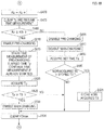
- the inrush current suppression processing of the second embodiment will be described with reference to a flowchart shown in FIG. 7 .
- the control circuit 38 disables the main-charging in S300 similarly to S100 in FIG. 5A .
- the pre-charging is already started at the point of start of the inrush current suppression processing in FIG. 7 .
- Processes of S310 to S330 are the same as the processes of S120 to S140 in FIG. 5A . That is, in S310 to S330, the bus voltage value VD is acquired, and the maximum value VDmax and the minimum value VDmin stored in the memory are updated according to magnitude relationships between the acquired bus voltage value VD and each of the maximum value VDmax and the minimum value VDmin stored in the memory.
- S345 it is determined whether the non-detection time Tz acquired in S340 is longer than or equal to the prescribed time Tth. If the non-detection time Tz is shorter than the prescribed time Tth, the processing returns to S310. If the non-detection time Tz is longer than or equal to the prescribed time Tth, the main-charging is disabled in S350, and the processing returns to S310.
- S365 it is determined whether the difference Vpp calculated in S360 is smaller than or equal to the difference threshold value Vth. If the difference Vpp is larger than the difference threshold value Vth, the main-charging is disabled in S370, and the processing proceeds to S380. If the difference Vpp is smaller than or equal to the difference threshold value Vth, the main-charging is enabled in S375. In this way, the main-charging of the smoothing capacitor 31 using the first switching element 56 is started. In S380, the maximum value VDmax and the minimum value VDmin currently stored in the memory are both cleared similarly to S235 in FIG. 5B , and the processing returns to S310.
- the second embodiment detailed so far provides effects equivalent to those of the above-described first embodiment in terms of the main-charging.
- a third embodiment is basically configured similarly to the first embodiment, and thus, an explanation will be given below of differences therebetween.
- the third embodiment differs from the first embodiment in the details of the inrush current suppression processing performed by the control circuit 38, especially, in the enabling condition for starting the main-charging.
- the enabling condition for the main-charging is that the difference Vpp, which is the difference between the peak voltage value and the capacitor voltage value, is smaller than or equal to the difference threshold value Vth.
- the enabling condition for the main-charging of the third embodiment is that a set time TS elapses after start of the pre-charging.
- the set time TS is determined based on the peak voltage value. Specifically, the larger the peak voltage value is, the longer the set time TS is.
- the inrush current suppression processing of the third embodiment will be described with reference to a flowchart shown in FIGS. 8A and 8B .
- processes of S400 to S425 are the same as the processes of S100 to S130 in the inrush current suppression processing of the first embodiment shown in FIG. 5A . That is, in the third embodiment, the peak voltage value is detected similarly to the first embodiment, although detection of the capacitor voltage value performed in the first embodiment is not performed.
- the control circuit 38 of the third embodiment determines whether the zero-cross has been detected based on the zero-cross detection signal from the zero-cross detection circuit 46. If the zero-cross has not been detected, the processing proceeds to S435. In S435, the current measurement value of the non-detection time Tz is acquired. In S440, it is determined whether the non-detection time Tz acquired in S435 is longer than or equal to the prescribed time Tth.
- S480 it is determined whether the zero-cross detection count Kz stored in the memory is greater than or equal to the prescribed number of times Kth. If the zero-cross detection count Kz is smaller than the prescribed number of times Kth, the pre-charging is disabled in S485, and the main-charging is disabled in S490. Then, the set time TS is acquired in S495.
- the pre-charging is enabled in S510.
- the time measurement of the pre-charging elapsed time Tp is started. In the case where the time measurement of the pre-charging elapsed time Tp has already been started, such time measurement is continued.
- the control circuit 38 starts time measurement of an elapsed time from the start-up. At this point of time, the pre-charging has already been started. Then, the processes of S495 to S505 in FIG. 8B are performed before the zero-cross is detected the prescribed number of times Kth or more, to thereby acquire the set time TS on the basis of the peak voltage value, and the acquired set time TS is stored in the memory as the pre-charging performance time.
Landscapes
- Engineering & Computer Science (AREA)
- Power Engineering (AREA)
- Physics & Mathematics (AREA)
- Nonlinear Science (AREA)
- Mechanical Engineering (AREA)
- Computer Security & Cryptography (AREA)
- Inverter Devices (AREA)
- Portable Power Tools In General (AREA)
- Emergency Protection Circuit Devices (AREA)
- Protection Of Static Devices (AREA)
- Direct Current Feeding And Distribution (AREA)
Abstract
Description
- The present disclosure relates to an electric working machine configured such that AC power is rectified by a rectifier circuit to drive a motor.
- Japanese Unexamined Patent Application Publication No.
2016-086639 - In the above-described electric power tool, it is preferred that fluctuations in voltage inputted to the inverter be small in order to drive the motor efficiently. Fluctuations in voltage inputted to the inverter can be reduced by, for example, increasing capacitance of the smoothing capacitor.
- However, the more the capacitance of the smoothing capacitor is increased, the larger the value of an inrush current flowing through the smoothing capacitor becomes at the start of input of the AC voltage. Further, the period of time in which the inrush current flows becomes longer as well.
- In a known technique that enables suppression of the inrush current at the start of input of the AC current, a switching element is coupled in series with the smoothing capacitor, and a resistive element is coupled in parallel with the switching element.
- With this technique, a charging current flows through the smoothing capacitor and the resistive element to thereby charge the smoothing capacitor by keeping the switching element OFF immediately after the AC current is inputted to activate the electric power tool. This charging current is regulated by the resistive element, and thus, flowing of large inrush current through the smoothing capacitor is inhibited.
- On the other hand, in order for smoothing by the smoothing capacitor to be efficiently performed while reducing loss, the switching element is turned ON so that the charging current may flow through the switching element via the smoothing capacitor.
- However, a large current could possibly flow through the smoothing capacitor when the switching element is turned ON to thereby damage various elements and so on if a timing of turning the switching element ON is improper.
- In one aspect of the present disclosure, it is desirable to be able to inhibit a large current from flowing through a capacitor when an AC power is inputted to an electric working machine.
- An electric working machine according to one aspect of the present disclosure comprises a motor, a rectifier circuit, a capacitor, a series switching element, a resistive element, a drive circuit, a peak voltage value acquirer, and a controller.
- The rectifier circuit is configured to rectify an AC power inputted from an AC power supply and to output a rectified power. The AC power fluctuates periodically. The capacitor is configured to be charged by the rectified power outputted from the rectifier circuit and to smooth the rectified power. The series switching element is a switching element coupled in series with the capacitor. The resistive element is coupled in parallel with the series switching element. The drive circuit is configured to drive the motor based on power smoothed by the capacitor. The peak voltage value acquirer is configured to acquire a peak voltage value, which is a maximum absolute value of a voltage of the AC power.
- The controller is configured to bring the series switching element into conduction in a case where the AC power is inputted to the rectifier circuit and where a specified conducting condition based on the peak voltage value acquired by the peak voltage value acquirer is satisfied.
- According to the thus-configured electric working machine, the conducting condition is set based on the peak voltage value after the AC power is inputted to the rectifier circuit. Then, the series switching element is brought into conduction when the conducting condition is satisfied. Accordingly, it can be inhibited that a large current flows through the capacitor when the series switching element is brought into conduction since the series switching element is brought into conduction at an appropriate timing.
- The electric working machine may further comprise a capacitor voltage value acquirer. The capacitor voltage value acquirer is configured to acquire a capacitor voltage value. The capacitor voltage value is a value of a charging voltage in the capacitor. The conducting condition may comprise a condition that a difference between the peak voltage value acquired by the peak voltage value acquirer and the capacitor voltage value acquired by the capacitor voltage value acquirer is smaller than or equal to a difference threshold value.
- In this case, the series switching element is brought into conduction when charging of the capacitor progresses and the difference between the peak voltage value of the AC power applied to the capacitor and the actual capacitor voltage value of the capacitor has become smaller than or equal to the difference threshold value. Accordingly, the series switching element can be brought into conduction in the state in which the difference between the peak voltage value and the capacitor voltage value has become small, and thus, the series switching element can be brought into conduction at a more appropriate timing. In addition, even in the event of rise and fall of the voltage of the AC power, an inrush current can be suppressed stably.
- In the case where the electric working machine is configured such that the conducting condition is set based on the difference between the peak voltage value and the capacitor voltage value as described above, the electric working machine may further comprise a current path and a voltage detector. The current path is configured to input the rectified power outputted from the rectifier circuit to the capacitor. The voltage detector is configured to output a signal indicating a voltage value in the current path. The peak voltage value acquirer may be configured to acquire the peak voltage value based on the signal outputted from the voltage detector. The capacitor voltage value acquirer may be configured to acquire the capacitor voltage value based on the signal outputted from the voltage detector.
- In this case, for example, in a state in which the voltage value in the current path is increased and decreased periodically, when the voltage value has become the maximum value, the peak voltage value acquirer can acquire the maximum value as the peak voltage value. Similarly, for example, in the state in which the voltage value in the current path is increased and decreased periodically, when the voltage value has become the minimum value, the capacitor voltage value acquirer can acquire the minimum value as the capacitor voltage value.
- The electric working machine may further comprise a parallel switching element. The parallel switching element is a switching element coupled in series with the resistive element and coupled in parallel with the series switching element. The controller may be configured to bring the parallel switching element into conduction when the AC power is inputted to the rectifier circuit, and to subsequently bring the series switching element into conduction when the conducting condition is satisfied.
- In this case, in addition to being able to appropriately set the timing of conduction of the series switching element, the controller can also adjust as appropriate the timing of starting flowing of the charging current via the resistive element prior to such conduction of the series switching element.
- In the case where the electric working machine comprises the parallel switching element, the electric working machine may further comprise a zero-cross detector. The zero-cross detector is configured to detect a zero-cross of a detection target. The detection target is a voltage or a current of the AC power. The controller may be configured to bring the parallel switching element into conduction within a specified period of time after the zero-cross is detected by the zero-cross detector. The specified period of time may be a period of time from detection of the zero-cross until a specified timing that is before a value of the detection target first reaches a peak value.
- The controller may be configured to bring the parallel switching element into conduction immediately after the zero-cross is detected by the zero-cross detector. "Immediately after the zero-cross is detected" is "immediately after the value of the detection target has become zero". Accordingly, by bringing the parallel switching element into conduction in such a state, it can be inhibited more effectively that a large current flows through the capacitor when the parallel switching element is brought into conduction.
- "Immediately after" mentioned here need not be strictly "immediately after". For example, a configuration may be adopted in which, in a state where the value of the detection target is still within a low level of a certain degree after detection of the zero-cross, the parallel switching element is brought into conduction after a specified process is performed.
- In the case where the electric working machine comprises the parallel switching element, the electric working machine may comprise the zero-cross detector, and the controller may be configured to bring the parallel switching element into conduction when the zero-cross is detected a prescribed number of times or more by the zero-cross detector after start of input of the AC power to the rectifier circuit.
- In this case, after start of input of the AC power to the electric working machine, the parallel switching element is brought into conduction to thereby allow the charging current to flow through the capacitor upon confirmation that the AC power is being inputted. Accordingly, when the electric working machine is connected to the AC power supply, the occurrence of sparks given off from the connection can be reduced.
- In the case where the electric working machine comprises the parallel switching element, the electric working machine may comprise the zero-cross detector, and the controller may be configured to bring the parallel switching element out of conduction when the zero-cross is not detected by the zero-cross detector continuously for a prescribed time or longer.
- In the case where the parallel switching element is brought out of conduction when the zero-cross is not detected continuously for the prescribed time or longer, the charging path to the capacitor is interrupted. Accordingly, when the electric working machine is again connected to the AC power supply, the occurrence of sparks given off from the connection can be reduced.
- The controller may determine the timing of conduction of the series switching element based on other conditions in addition to the conducting condition. For example, the controller may be configured to bring the series switching element into conduction in a case where the conducting condition is satisfied and where a voltage value of the rectified power outputted from the rectifier circuit is smaller than or equal to the capacitor voltage value.
- In this case, when the series switching element is brought into conduction, the value of the output voltage of the rectifier circuit is smaller than or equal to the value of the charging voltage across the capacitor. Accordingly, it can be effectively inhibited that a large current flows from the rectifier circuit to the capacitor.
- Moreover, for example, the electric working machine may comprise the zero-cross detector configured to detect a zero-cross of a detection target. The detection target is a voltage or a current of the AC power. The controller may be configured to bring the series switching element into conduction when the conducting condition is satisfied and within a specified period of time that is after the zero-cross is detected by the zero-cross detector. The specified period of time may be a period of time from detection of the zero-cross until a specified timing that is before a value of the detection target first reaches a peak value.
- The controller may be configured, when the conducting condition is satisfied, to bring the series switching element into conduction immediately after the zero-cross is detected by the zero-cross detector. By bringing the series switching element into conduction immediately after detection of the zero-cross, that is, immediately after the value of the detection target has become zero, it can be effectively inhibited that a large current flows to the capacitor when the series switching element is brought into conduction. "Immediately after" mentioned here also need not be strictly "immediately after".
- The controller may be configured to bring the series switching element out of conduction when the zero-cross is not detected continuously for a prescribed time or longer. In this case, it can be inhibited that the series switching element is kept in conduction despite the electric working machine not being connected to the AC power supply. Accordingly, it can be effectively inhibited that, when the electric working machine is connected to the AC power supply, sparks are given off from the connection.
- The controller may be configured to determine a set time to be used as the conducting condition, based on the peak voltage value acquired by the peak voltage value acquirer. In this case, the conducting condition may comprise a condition that the set time elapses from a specified time measurement start timing that is after start of input of the AC power to the rectifier circuit.
- In this case, since the set time is determined based on the peak voltage value, the series switching element can be brought into conduction in the state in which the difference between the peak voltage value of the AC power applied to the capacitor and the actual capacitor voltage value of the capacitor has become moderately small. Accordingly, the controller can bring the series switching element into conduction at an appropriate timing.
- Also in the case where the conducting condition is that the set time elapses from the time measurement start timing as described above, the electric working machine may further comprise a parallel switching element. The parallel switching element is coupled in parallel with the series switching element. The controller may be configured to bring the parallel switching element into conduction when input of the AC power to the rectifier circuit is started, and to subsequently bring the series switching element into conduction when the conducting condition is satisfied. The time measurement start timing may be a timing at which the parallel switching element is brought into conduction.
- In this case, the timing of bringing the series switching element into conduction is set based on the timing of starting the charging of the capacitor via the resistive element. Accordingly, the controller can bring the series switching element into conduction at a more appropriate timing.
- The controller may be configured to determine the set time such that the larger the peak voltage value is, the longer the set time is. It can be conceivable that the larger the peak voltage value is, the longer the time required to bring the value of the charging voltage across the capacitor closer to the peak voltage value is. Accordingly, by determining the set time such that the larger the peak voltage value is, the longer the set time is, the series switching element can be brought into conduction in the state in which the difference between the peak voltage value and the value of the charging voltage across the capacitor has become small to a necessary and sufficient extent.
- Another aspect of the present disclosure is a method for smoothing an AC power fluctuating periodically supplied to an electric working machine.
- The electric working machine comprises:
- a motor;
- a rectifier circuit configured to rectify the AC power and to output a rectified power;
- a capacitor configured to be charged by the rectified power outputted from the rectifier circuit and to smooth the rectified power;
- a switching element coupled in series with the capacitor;
- a resistive element coupled in parallel with the switching element; and
- a drive circuit configured to drive the motor based on a power smoothed by the capacitor.
- The method comprises:
- acquiring a peak voltage value, which is a maximum absolute value of a voltage of the AC power; and
- bringing the switching element into conduction when a specified conducting condition based on the peak voltage value is satisfied.
- Such a method can also exert effects similar to those of the above-described electric working machine.
- Example embodiments of the present disclosure will be described below by way of example with reference to the accompanying drawings, in which:
-
FIG. 1 is a perspective view showing an electric working machine of a first embodiment; -
FIG. 2 is an electric circuit diagram of the electric working machine of the first embodiment; -
FIG. 3 is an electric circuit diagram of a part extracted from the electric circuit diagram inFIG. 2 , particularly showing detailed configurations of an inrush current suppression circuit and a power-supply circuit; -
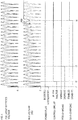
FIG. 4 is an explanatory diagram showing a charging state of a smoothing capacitor in the electric working machine of the first embodiment after insertion of a power plug; -
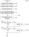
FIG. 5A is a flowchart showing part of an inrush current suppression processing of the first embodiment; -
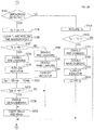
FIG. 5B is a flowchart showing the rest of the inrush current suppression processing of the first embodiment; -
FIG. 6 is an electric circuit diagram of an inrush current suppression circuit of a second embodiment. -
FIG. 7 is a flowchart showing an inrush current suppression processing of the second embodiment; -
FIG. 8A is a flowchart showing part of an inrush current suppression processing of a third embodiment; -
FIG. 8B is a flowchart showing the rest of the inrush current suppression processing of the third embodiment; and -
FIG. 9 is an explanatory diagram showing a set time table of the third embodiment. - As shown in
FIG. 1 , anelectric working machine 1 of the present embodiment, which is configured as a circular saw, comprises abase 2 and amain body 3. Thebase 2 is a substantially rectangular member to be brought into contact with an upper surface of a workpiece when cutting operation is performed on the workpiece by means of the electric workingmachine 1. Themain body 3 is mainly arranged on an upper surface side of thebase 2. - The
main body 3 comprises asaw blade 4 of a circular shape, asaw blade case 5, acover 6, a body casing 7, and ahandle 10. Thesaw blade 4 is arranged on the right side of themain body 3 with respect to a cutting advance direction. Thesaw blade case 5 is provided so as to cover and contain therein substantially an upper half of thesaw blade 4. Thecover 6 is provided so as to cover substantially a lower half of thesaw blade 4. - The
cover 6 is designed to open and close, andFIG. 1 shows a state in which thecover 6 is closed. By moving the electric workingmachine 1 in the cutting advance direction while cutting the workpiece, thecover 6 is rotated in a counterclockwise direction inFIG. 1 about a rotation center of thesaw blade 4, to thereby be gradually opened. As a result, thesaw blade 4 is exposed, and an exposed part of thesaw blade 4 cuts into the workpiece. - The body casing 7 is arranged on the left side of the
main body 3 with respect to the cutting advance direction. The body casing 7 comprises amotor container 8 of a substantially cylindrical shape and acontroller container 9 of a substantially cuboidal shape. - The
motor container 8 contains therein a motor 15 (seeFIG. 2 ). Themotor 15 is a drive source to rotate thesaw blade 4. Thecontroller container 9 contains therein a controller 30 (seeFIG. 2 ). Thecontroller 30 controls driving of themotor 15. - In the
main body 3, provided between themotor container 8 and thesaw blade 4 is a not-shown gear mechanism. The gear mechanism decelerates rotation of themotor 15 and transmits the decelerated rotation to thesaw blade 4. The body casing 7 has afirst air vent 7a arranged in a left lateral face of themotor container 8 with respect to the cutting advance direction, and has asecond air vent 7b arranged in a rear end face of thecontroller container 9 with respect to the cutting advance direction. - The
handle 10 to be grabbed by a user of the electric workingmachine 1 is provided to themain body 3 so as to form an arch-like shape. A first end of thehandle 10 is fixed on a rear end side of themain body 3 with respect to the cutting advance direction, and a second end of thehandle 10 is fixed to themain body 3 at a position forward relative to the first end with respect to the cutting advance direction. In the present embodiment, themain body 3 and thehandle 10 are integrally formed of, for example, a resin material. - The
handle 10 has anoperation switch 11 of a trigger type provided on a side thereof facing the body casing 7. The user of the electric workingmachine 1 can operate theoperation switch 11 while grabbing thehandle 10. Further, when the user presses down a not-shown lock button while performing a pulling operation of theoperation switch 11, theoperation switch 11 can be locked in such a pulled state. - From a rear end of the
main body 3 with respect to the cutting advance direction, apower cord 12 is drawn out. Provided at a leading end of thepower cord 12 is a not-shown power plug. Thepower cord 12 is a cord to take in electric power for driving themotor 15. - An electrical configuration of the electric working
machine 1 will now be described with reference toFIGS. 2 and3 . As shown inFIG. 2 , the electric workingmachine 1 comprises themotor 15, thecontroller 30, a smoothingcapacitor 31, anindicator 32, and aswitch body 40. - When the power plug provided at the leading end of the
power cord 12 is inserted into a socket of an external power supply, that is, anAC power supply 100, AC power is inputted from theAC power supply 100 to thecontroller 30 via thepower cord 12. Thepower cord 12 compriseselectric wires electric wire 12a is provided with afuse 13. When a current flowing through theelectric wire 12a becomes excessively large to fuse thefuse 13, theelectric wire 12a is broken, to thereby block input of AC power to thecontroller 30. - The
motor 15 is a brushless motor in the present embodiment. Themotor 15, which is coupled to aninverter 50 in thecontroller 30, is rotationally driven by being supplied with current from theinverter 50. Coupled to themotor 15 is afan 16 to cool down themotor 15. Rotation of themotor 15 causes rotation of thefan 16. - The
motor 15 comprises a rotation sensor 33 that detects a rotational position of themotor 15. The rotation sensor 33 of the present embodiment comprises three Hall sensors. These Hall sensors are arranged around a rotor of themotor 15 so as to be separated from each other by an electric angle of 120 degrees. Signals from these Hall sensors are inputted to acontrol circuit 38 in thecontroller 30. - More specifically, the smoothing
capacitor 31 of the present embodiment comprisescapacitors capacitor 31 is parallel-combined capacitance of thecapacitors capacitors - Instead of the
capacitors capacitor 31 may comprise a single capacitor, or may comprise a plurality of capacitors coupled to one another in parallel, in series, or in series and parallel. - The
indicator 32 visually indicates various information to the user of the electric workingmachine 1. Theindicator 32 comprises an LED in the present embodiment. Theindicator 32 is controlled by thecontroller 30. - The
switch body 40 is a member to perform electrical output corresponding to an operation state of theoperation switch 11 by the user, and comprises at least aswitch contact 40a. Theswitch contact 40a is provided on abus line 39 leading from arectifier circuit 35 to theinverter 50, and electrically completes or interrupts thebus line 39. In the present embodiment, however, a resistor R1 is coupled in parallel with theswitch contact 40a on thebus line 39, and thus, thebus line 39 is not completely interrupted even when theswitch contact 40a is turned OFF. - In a state in which the pulling operation of the
operation switch 11 is not performed, theswitch contact 40a enters an OFF state to interrupt thebus line 39. On the other hand, in a state in which the pulling operation of theoperation switch 11 is performed, theswitch contact 40a enters an ON state to complete thebus line 39. Further, theswitch body 40 is configured to output to thecontrol circuit 38 in thecontroller 30 an operation signal indicating whether the pulling operation of theoperation switch 11 has been performed. The operation signal in the present embodiment is an electrical signal indicating the ON state or the OFF state of theswitch contact 40a. - The
controller 30 is configured to convert the AC power supplied from theAC power supply 100 into electric power for driving themotor 15 and to supply the converted power to themotor 15. Various circuits in thecontroller 30 of the present embodiment and their components may be mounted on a single circuit board. - The
controller 30 comprises therectifier circuit 35, a smoothingcircuit 36, an intelligent power module (IPM) 37, thecontrol circuit 38, avoltage detection circuit 42, acurrent detection circuit 43, a power-supply circuit 44, adischarge circuit 45, a zero-cross detection circuit 46, and anindicator drive circuit 47. - The
rectifier circuit 35 comprises a diode bridge. The diode bridge comprises four diodes, and full-wave rectifies the AC power inputted to therectifier circuit 35. The electric power rectified by therectifier circuit 35 is outputted to thebus line 39. - The smoothing
circuit 36 smooths the rectified electric power, which has been outputted from therectifier circuit 35. The smoothingcircuit 36 comprises the smoothingcapacitor 31 and an inrushcurrent suppression circuit 48. A first end of the smoothingcapacitor 31 is coupled to thebus line 39, and a second end of the smoothingcapacitor 31 is coupled to the inrushcurrent suppression circuit 48. In the present embodiment, the smoothingcapacitor 31 is not mounted on the circuit board of thecontroller 30, and is arranged separately from the circuit board of thecontroller 30. - More specifically, as shown in
FIG. 3 , the inrushcurrent suppression circuit 48 comprises afirst switching element 56, asecond switching element 57, aresistive element 58, andgate drive circuits first switching element 56 and thesecond switching element 57 are each an N-channel MOSFET in the present embodiment. - The
first switching element 56 is provided in series with the smoothingcapacitor 31 on a current path leading from thebus line 39 through the smoothingcapacitor 31 to a ground line. Specifically, a drain of thefirst switching element 56 is coupled to the second end of the smoothingcapacitor 31, and a source of thefirst switching element 56 is coupled to the ground line. - While the
second switching element 57 and theresistive element 58 are coupled in series with each other, they are coupled in parallel with thefirst switching element 56. More specifically, a first end of theresistive element 58 is coupled to the drain of thefirst switching element 56, and a second end of theresistive element 58 is coupled to a drain of thesecond switching element 57. A source of thesecond switching element 57 is coupled to the ground line. - The
resistive element 58 is a PTC thermistor in the present embodiment. However, the PTC thermistor is one example of theresistive element 58, and theresistive element 58 may be a resistive element other than the PTC thermistor. - The
first switching element 56 is turned ON and OFF via thegate drive circuit 61 in accordance with a drive command from thecontrol circuit 38. Thesecond switching element 57 is turned ON and OFF via thegate drive circuit 62 in accordance with a drive command from thecontrol circuit 38. Thefirst switching element 56 is brought into conduction when turned ON, and is brought out of conduction when turned OFF. - According to such a configuration, when the AC power is being inputted to the
rectifier circuit 35 via thepower cord 12, the charging current flows through the smoothingcapacitor 31, theresistive element 58, and thesecond switching element 57 to thereby charge the smoothingcapacitor 31 upon turning ON of thesecond switching element 57. On the other hand, the charging current flows through the smoothingcapacitor 31 and thefirst switching element 56 to thereby charge the smoothingcapacitor 31 upon turning ON of thefirst switching element 56. - That is, when either one of the
first switching element 56 or thesecond switching element 57 is turned ON, the charging current flows through the smoothingcapacitor 31 to thereby charge the smoothingcapacitor 31. - It is to be noted that, since the
resistive element 58 is coupled in series with thesecond switching element 57, the value of the charging current when thesecond switching element 57 is turned ON in a state in which thefirst switching element 56 is OFF is kept lower than the value of the charging current at the time when thefirst switching element 56 is turned ON. - Returning to
FIG. 2 , theIPM 37 comprises, within a single package thereof, theinverter 50, a drivesignal generation circuit 51, and aprotection circuit 52. - The
inverter 50 switches conduction states of respective phase coils of themotor 15 and controls conduction currents flowing through the respective phase coils, to thereby rotationally drive themotor 15. Theinverter 50 comprises switching elements Q1, Q2, and Q3, which are provided as high-side switches, and switching elements Q4, Q5, and Q6, which are provided as low-side switches. - The switching elements Q1, Q2, and Q3 are each provided between the corresponding phase coil of the
motor 15 and thebus line 39. The switching elements Q4, Q5, and Q6 are each provided between the corresponding phase coil of themotor 15 and the ground line. - The switching elements Q1 to Q6 are insulated gate bipolar transistors (IGBTs) in the present embodiment. However, the IGBTs are just one example of the switching elements Q1 to Q6, and the switching elements Q1 to Q6 may be switching elements of other types.
- The drive
signal generation circuit 51 turns the switching elements Q1 to Q6 in theinverter 50 ON and OFF individually in accordance with the drive commands from thecontrol circuit 38. The switching elements Q1 to Q6 are brought into conduction when turned ON, and are brought out of conduction when turned OFF. When the electric workingmachine 1 has entered a specified state, theprotection circuit 52 causes the drivesignal generation circuit 51 to stop themotor 15 by forcibly turning the switching elements Q1 to Q6 OFF, and outputs an error signal to thecontrol circuit 38. Examples of the specified state may include occurrence of, for example, an overheat abnormality in theIPM 37, detection of an abnormality in the power-supply circuit 44 based on a control voltage Vcc inputted to theIPM 37, and detection of overcurrent based on a current detection signal from thecurrent detection circuit 43, as will be described later. - The
motor 15 of the present embodiment is a high rotation type motor. One reason for adopting the high rotation type motor as themotor 15 is to enable feedback control (i.e., constant rotation control) so that themotor 15 may have a constant rotational speed by pulse-width modulation (PWM) driving, and further to expand, as wide as possible, the load region in which the rotational speed of themotor 15 can be maintained constant. In the present embodiment, degradation in the rotational speed due to load in the practical region is inhibited by using a motor that can be rotated at a high rotational speed relative to another motor with respect to the same current value. - The maximum rotational speed of the
motor 15 of the present embodiment is, for example, 5,000 rpm or more, which is measured as the rotational speed of thesaw blade 4, and is controlled to maintain, for example, 4,000 rpm to 4,500 rpm by the constant rotation control. - Moreover, in the present embodiment, in order to inhibit reduction of torque while maintaining the high rotational speed, the value of the current flowing through the
motor 15 when driving themotor 15 is set at a relatively large value. To flow a current having a large current value through the high rotation type motor makes it possible to maintain necessary and sufficient torque even at high rotational speeds. As a result, a sufficient load region can be secured in which the rotational speed can be maintained constant. - Furthermore, in the present embodiment, a capacitor having a middle capacitance is used as the smoothing
capacitor 31. Such a capacitor has electrostatic capacity of, for example, around 1,000 µF (e.g., a value in the range of 470 µF to 2,000 µF). - The use of the capacitor having the middle capacitance as the smoothing
capacitor 31 makes it possible to suppress peak current in the current flowing through themotor 15, to thereby reduce current ripple, as compared with a case where a capacitor having small capacitance is used. This makes it possible to raise an average value of the current that can flow without causing theprotection circuit 52 within theIPM 37 to perform an overcurrent protection function. As a result, the maximum torque (the maximum output) of themotor 15 can be increased. In addition, effective reduction of current ripple enables inhibition of demagnetization of a permanent magnet used in themotor 15, and themotor 15 can be designed to be smaller. - Still further, in the present embodiment, the
IPM 37 is provided as a drive circuit for themotor 15. TheIPM 37 comprises the above-described switching elements Q1 to Q6. These switching elements Q1 to Q6 are contained in a single package. To use theIPM 37 as the drive circuit is just one example. Each of the switching elements Q1 to Q6 may be, for example, a discrete component, and may be mounted individually on the circuit board. - The
IPM 37 is configured such that heat generated by the switching elements Q1 to Q6 can be radiated efficiently. In addition, since the switching elements Q1 to Q6 can be handled as a single component, arrangement on the circuit board is highly flexible. In sum, in the present embodiment, theIPM 37 is adopted as the drive circuit for themotor 15 with the aim of maintaining necessary heat radiation performance while increasing flexibility in arrangement of the components. - The use of the high rotation type motor as the
motor 15 and the capacitor having a middle capacitance as the smoothingcapacitor 31 is just one example. - The
voltage detection circuit 42, which is coupled to thebus line 39, detects a bus voltage value VD, which is a voltage value of thebus line 39, and outputs to the control circuit 38 a voltage detection signal indicating the detected bus voltage value VD. - The
current detection circuit 43 is provided on a current path leading from theinverter 50 to the ground line. Thecurrent detection circuit 43 detects a load current value, which is the value of load current flowing through this current path. Thecurrent detection circuit 43 outputs a current detection signal indicating the detected load current value to thecontrol circuit 38 and theprotection circuit 52. Theprotection circuit 52 monitors the load current value on the basis of the current detection signal inputted from thecurrent detection circuit 43. When the load current value exceeds a threshold value, theprotection circuit 52 forcibly turns the switching elements Q1 to Q6 OFF regardless of the contents of the drive command from thecontrol circuit 38. - The power-
supply circuit 44 generates electric power for operating the respective elements within thecontroller 30. More specifically, as shown inFIG. 3 , the power-supply circuit 44 comprises a switchingpower supply 66, alinear power supply 67, and a voltagedrop detection circuit 68. - The electric power smoothed by the smoothing
circuit 36 is inputted to the switchingpower supply 66 through thebus line 39 and via a diode D1 and afilter circuit 69. The switchingpower supply 66 generates the control voltage Vcc having a specified DC voltage value on the basis of the inputted electric power, and outputs the generated control voltage Vcc. The control voltage Vcc is supplied to the respective elements within thecontroller 30, including theIPM 37 and the inrushcurrent suppression circuit 48, and is used for operation of the respective elements. - The control voltage Vcc is also inputted to the
linear power supply 67. Thelinear power supply 67 generates a control voltage Vdd having a specified DC voltage value on the basis of the inputted control voltage Vcc, and outputs the generated control voltage Vdd. The control voltage Vdd generated by thelinear power supply 67 is supplied to the respective elements within thecontroller 30, including thecontrol circuit 38, and is used for operation of the respective elements. - When the value of the input voltage inputted to the power-
supply circuit 44 is decreased to a value indicating that the control voltage Vcc and the control voltage Vdd cannot be maintained within normal ranges, the voltagedrop detection circuit 68 causes thelinear power supply 67 to stop output of the control voltage Vdd. - When the power plug is pulled out to thereby stop input of the AC power to the electric working
machine 1, thedischarge circuit 45 promptly discharges the charging power of the smoothingcapacitor 31 to thereby stop themotor 15 promptly. Thedischarge circuit 45 of the present embodiment comprises, for example, a resistor. A first end of this resistor is coupled to thebus line 39, and a second end of this resistor is coupled to the ground line. - The zero-
cross detection circuit 46 detects the voltage value of the AC power inputted from theAC power supply 100 to thereby detect a zero-cross point of the value of the AC voltage. In other words, the zero-cross detection circuit 46 detects a timing at which the value of the AC voltage becomes 0. Alternatively, the zero-cross detection circuit 46 detects the current value of the AC power inputted from theAC power supply 100 to thereby detect a zero-cross point of the value of the AC current. In other words, the zero-cross detection circuit 46 detects a timing at which the value of the AC current becomes 0. Each time the zero-cross detection circuit 46 detects the zero-cross point, the zero-cross detection circuit 46 outputs to the control circuit 38 a zero-cross detection signal indicating that the zero-cross point has been detected. - The
indicator drive circuit 47 drives theindicator 32 in accordance with an indicator control signal from thecontrol circuit 38. Theindicator drive circuit 47 can cause theindicator 32 to, for example, emit a green light, emit a red light, or blink the light. - In the
bus line 39, theswitch contact 40a is coupled downstream of a position where the smoothingcircuit 36 is coupled. When theswitch contact 40a is ON, the electric power smoothed by the smoothingcircuit 36 is inputted to theIPM 37 via theswitch contact 40a. - Coupled between a path in the
bus line 39 between theswitch contact 40a and theIPM 37 and the ground line is a snubber capacitor Cs that removes or reduces high-frequency noise from thebus line 39. The snubber capacitor Cs is a non-polar capacitor and has much smaller capacitance than that of the smoothingcapacitor 31. - If the
switch contact 40a is arranged in the preceding stage of the smoothingcircuit 36, charging of the smoothingcapacitor 31 is started when the pulling operation of theoperation switch 11 is performed to turn theswitch contact 40a ON. Thus, start-up of themotor 15 is delayed. - In contrast, the
switch contact 40a is arranged in the subsequent stage of the smoothingcircuit 36 in the present embodiment. Due to such a configuration, charging of the smoothingcapacitor 31 is performed upon insertion of the power plug, even when the pulling operation of theoperation switch 11 is not performed. Thus, after insertion of the power plug, themotor 15 can be started promptly when the pulling operation of theoperation switch 11 is performed to turn theswitch contact 40a ON. - Further, in the
bus line 39, the resistor R1 is coupled in parallel with theswitch contact 40a. In the present embodiment, the resistor R1 has a relatively large resistance of, for example, several hundred kΩ. Due to existence of the resistor R1, the snubber capacitor Cs is charged in advance upon insertion of the power plug, even when theswitch contact 40a is OFF. - Due to such a configuration, inrush current to the snubber capacitor Cs is suppressed when the pulling operation of the
operation switch 11 is performed to turn theswitch contact 40a ON after insertion of the power plug. Thus, even when chattering of theswitch contact 40a occurs, welding failure of theswitch contact 40a is inhibited. - In the
controller 30, provided between the preceding stage of therectifier circuit 35, that is, thefuse 13, and therectifier circuit 35 is avaristor 41 that protects internal circuits of thecontroller 30 from overvoltage. - In a supply path of the AC power, the
fuse 13 is arranged in the preceding stage of thevaristor 41. Thus, in a case of a short-circuit failure of thevaristor 41, blowout of thefuse 13 occurs to interrupt input of the AC power to the electric workingmachine 1. - The
varistor 41 is arranged at a specified position within thecontroller container 9 shown inFIG. 1 . This specified position may be a position where a body of thevaristor 41 cannot be visually observed from outside of the electric workingmachine 1 through thesecond air vent 7b and where sparks given off from thevaristor 41 in the event of the short-circuit failure of thevaristor 41 also cannot be visually observed from outside of the electric workingmachine 1 through thesecond air vent 7b. - In the present embodiment, the
control circuit 38 comprises a microcomputer comprising a CPU, a memory, and so on. The memory includes at least one of various semiconductor memories, such as a RAM, a ROM, and a flash memory. Various functions of thecontrol circuit 38 are performed by the CPU's execution of programs stored in a non-transitory tangible storage medium. In this example, the memory corresponds to the non-transitory tangible storage medium in which the programs are stored. - The microcomputer provided in the
control circuit 38 may be one in number, or may be two or more in number. Further, the functions of thecontrol circuit 38 are performed not only by software. Some or all of the functions of thecontrol circuit 38 may be performed by hardware configured with a logic circuit, an analog circuit, and so on combined together. More specifically, thecontrol circuit 38 may be a combination of various individual electronic components, or may be an Application Specified Integrated Circuit (ASIC), Application Specific Standard Product (ASSP), or a programmable logic device such as a Field Programmable Gate Array (FPGA), or may be a combination thereof. - When the
control circuit 38 detects the pulling operation of theoperation switch 11 on the basis of the operation signal from theswitch body 40, thecontrol circuit 38 outputs, to the drivesignal generation circuit 51 in theIPM 37, individual drive signals for the respective switching elements Q1 to Q6, to thereby drive themotor 15. - The
control circuit 38 can detect the bus voltage value VD on the basis of the voltage detection signal inputted from thevoltage detection circuit 42. Thecontrol circuit 38 can detect a timing of the zero-cross point on the basis of the zero-cross detection signal inputted from the zero-cross detection circuit 46. - The
control circuit 38 controls operation of theindicator 32 via theindicator drive circuit 47. For example, thecontrol circuit 38 causes theindicator 32 to illuminate green or to extinguish. Further, for example, when thecontrol circuit 38 detects that the load current value indicates an overcurrent state on the basis of the current detection signal inputted from thecurrent detection circuit 43, thecontrol circuit 38 causes theindicator 32 to illuminate red. After theindicator 32 is caused to illuminate red, when the overcurrent state indicated by the load current value has continued for a specified period of time, thecontrol circuit 38 forces the switching elements Q1 to Q6 OFF to stop themotor 15. - The
control circuit 38 controls the inrushcurrent suppression circuit 48 within the smoothingcircuit 36 by executing an inrush current suppression processing, which will be described below. Specifically, thecontrol circuit 38 individually controls the switchingelements current suppression circuit 48 to be ON or OFF, to thereby control charging of the smoothingcapacitor 31. - Here, a supplementary explanation will be given about differences between the overcurrent protection function of the
control circuit 38 and the overcurrent protection function of theprotection circuit 52 within theIPM 37. - The overcurrent protection function of the
protection circuit 52 within theIPM 37 is to forcibly stop themotor 15 by directly causing the drivesignal generation circuit 51 to forcibly turn the switching elements Q1 to Q6 OFF without involving thecontrol circuit 38, when the load current value detected by thecurrent detection circuit 43 exceeds the threshold value. This overcurrent protection function enables, for example, protection against an instantaneous current (for example, inhibition of demagnetization). Thus, the threshold value and responsiveness for this overcurrent protection function are higher than those for the overcurrent protection function of thecontrol circuit 38. - On the other hand, the overcurrent protection function of the
control circuit 38 enables, for example, protection against an average current (for example, protection against burnout of themotor 15, theIPM 37, and so on). In this case, thecontrol circuit 38 may determine the overcurrent state when an average current value acquired from the load current value detected by thecurrent detection circuit 43 is greater than or equal to a given threshold value. In this case, theindicator 32 may be caused to illuminate red as described above. Then, thecontrol circuit 38 may stop driving of themotor 15 when the overcurrent state has continued for the specified period of time. The threshold value used for the overcurrent protection function of thecontrol circuit 38 may be smaller than the threshold value used by theprotection circuit 52 within theIPM 37. - An explanation will be given below, with reference to
FIG. 4 , of an example of operation of the smoothingcircuit 36 after the power plug is inserted into the socket of theAC power supply 100 to start input of AC power to the electric workingmachine 1. - Upon insertion of the power plug into the socket of the
AC power supply 100 at a time t1, AC power is inputted to thecontroller 30. When AC power is inputted to thecontroller 30, the power-supply circuit 44 starts up to generate the control voltage Vcc and the control voltage Vdd, which are supplied to the respective elements within thecontroller 30. This causes thecontrol circuit 38 to start up at a time t2. - After the start-up, the
control circuit 38 detects a zero-cross on the basis of the zero-cross detection signal from the zero-cross detection circuit 46, and enables pre-charging at a time t3, that is, immediately after the Kth zero-cross is detected (Kth is a prescribed number of times the zero-cross is detected).FIG. 4 illustrates a case where the prescribed number of times Kth is, for example, five. In other words,FIG. 4 illustrates an example in which, after thecontrol circuit 38 starts up at the time t2, the pre-charging is enabled after the zero-cross is detected five times. - The pre-charging refers to charging the smoothing
capacitor 31 using theresistive element 58 and thesecond switching element 57 by turning ON thesecond switching element 57 within the inrushcurrent suppression circuit 48. "Enabling" the pre-charging refers to turning thesecond switching element 57 ON. "Disabling" the pre-charging refers to turning thesecond switching element 57 OFF. - Before the pre-charging is started, the bus voltage value VD is equal to the full-wave rectified voltage value, which is the value of a voltage outputted from the
rectifier circuit 35. On the other hand, upon start of the pre-charging at the time t3, the capacitor voltage value, which is the value of charging voltage across the smoothingcapacitor 31, is gradually increased. Thus, the bus voltage value VD is equal to the full-wave rectified voltage value during a period of time in which the full-wave rectified voltage value is greater than or equal to the capacitor voltage value, and the bus voltage value VD is equal to the capacitor voltage value during a period of time in which the full-wave rectified voltage value is smaller than the capacitor voltage value. - Upon start of the pre-charging, the capacitor voltage value becomes closer to a peak voltage value of the AC power. The peak voltage value is the maximum absolute value of the voltage of the periodically fluctuating AC power. After start of the pre-charging, the
control circuit 38 enables main-charging when a specified enabling condition is satisfied. - The main-charging refers to putting the smoothing
capacitor 31 into a state chargeable using thefirst switching element 56 by turning ON thefirst switching element 56 within the inrushcurrent suppression circuit 48. "Enabling" the main-charging refers to turning thefirst switching element 56 ON. "Disabling" the main-charging refers to turning thefirst switching element 56 OFF. - In the present embodiment, the pre-charging is continuously kept enabled even after the main-charging is enabled. However, the pre-charging may be disabled when the main-charging is enabled.
- In the present embodiment, the enabling condition for starting the main-charging is that a difference Vpp, which is a difference between the peak voltage value and the capacitor voltage value, becomes smaller than or equal to a difference threshold value Vth. When the
control circuit 38 detects, at a time t4, that the enabling condition is satisfied, that is, that the difference Vpp has become smaller than or equal to the difference threshold value Vth, thecontrol circuit 38 enables the main-charging. Upon enabling of the main-charging, charging of the smoothingcapacitor 31 progresses rapidly by the main-charging, and the smoothingcapacitor 31 is charged to a level approximately equal to the peak voltage value of the AC power. - Next, an explanation will be given below, with reference to a flowchart shown in
FIGS. 5A and5B , of the inrush current suppression processing performed by thecontrol circuit 38 to achieve the operation of the smoothingcircuit 36 shown inFIG. 4 . Upon start-up, thecontrol circuit 38 reads from the memory a program of the inrush current suppression processing shown inFIGS. 5A and5B , and executes the program. - Upon start of the inrush current suppression processing, the
control circuit 38 disables the pre-charging in S100, and disables the main-charging in S105. That is, the pre-charging and the main-charging are both to be surely disabled in an initial state after the start-up. In S110, theindicator 32 is turned OFF, that is, the LED is extinguished. - In S115, time measurement of a non-detection time Tz is started. The non-detection time Tz indicates duration of a state in which no zero-cross is detected.
- In S120, the bus voltage value VD is acquired based on the voltage detection signal from the
voltage detection circuit 42. In S125, it is determined whether the bus voltage value VD acquired in S120 is greater than the maximum value VDmax, which is temporarily stored in the memory. If the bus voltage value VD is smaller than or equal to the maximum value VDmax, the processing proceeds to S135. If the bus voltage value VD is greater than the maximum value VDmax, the processing proceeds to S130. - In S130, the maximum value VDmax is updated from that currently stored in the memory to the bus voltage value VD acquired this time. Each time the bus voltage value VD greater than the currently stored one is acquired, the maximum value VDmax stored in the memory is updated to the acquired bus voltage value VD by the process of S130.
- In S135, it is determined whether the bus voltage value VD acquired in S120 is smaller than the minimum value VDmin, which is temporarily stored in the memory. If the bus voltage value VD is greater than or equal to the minimum value VDmin, the processing proceeds to S145. If the bus voltage value VD is smaller than the minimum value VDmin, the processing proceeds to S140.
- In S140, the minimum value VDmin is updated from that currently stored in the memory to the bus voltage value VD acquired this time. Each time the bus voltage value VD smaller than the currently stored one is acquired, the minimum value VDmin stored in the memory is updated to the acquired bus voltage value VD by the process of S140.
- In S145, it is determined whether the zero-cross has been detected based on the zero-cross detection signal from the zero-
cross detection circuit 46. If the zero-cross has not been detected, the processing proceeds to S150. In S150, the current measurement value of the non-detection time Tz is acquired. - In S155, it is determined whether the non-detection time Tz acquired in S150 is longer than or equal to a prescribed time Tth. The prescribed time Tth may be any value that is longer than a half cycle of the AC power.
- If the non-detection time Tz is shorter than the prescribed time Tth, the processing returns to S120. If the non-detection time Tz is longer than or equal to the prescribed time Tth, the pre-charging is disabled in S160, the main-charging is disabled in S165, the
indicator 32 is turned OFF in S170, and a later-described zero-cross detection count Kz is cleared to zero in S175. Then, the processing returns to S120. The zero-cross detection count Kz is stored in the memory, and is counted up in the process of S180, which will be described below. - In S145, if the zero-cross is detected, the processing proceeds to S180. In S180, the zero-cross detection count Kz stored in the memory is updated to the value obtained by adding 1 to the currently stored value. In S185, the non-detection time Tz being measured currently is cleared to zero, and the time measurement is resumed.
- In S190, it is determined whether the zero-cross detection count Kz stored in the memory is greater than or equal to the prescribed number of times Kth. The prescribed number of times Kth may be decided as appropriate, and may be decided within the range of, for example, around five times.
- If the zero-cross detection count Kz is smaller than the prescribed number of times Kth, the pre-charging is disabled in S195, the main-charging is disabled in S200, and the
indicator 32 is turned OFF in S205. Then, the processing proceeds to S235. If the zero-cross detection count Kz is greater than or equal to the prescribed number of times Kth, the pre-charging is enabled in S210. In this way, the pre-charging of the smoothingcapacitor 31 using theresistive element 58 and thesecond switching element 57 is started. - In S215, the
indicator 32 is turned ON. ON of theindicator 32 mentioned here refers to causing the LED in theindicator 32 to illuminate green. Such illumination of theindicator 32 in green makes it possible to indicate to the user that the electric workingmachine 1 is active and can be operated. - After the
indicator 32 is turned ON in S215, theindicator 32 is turned OFF in S170 if, for example, the power plug is pulled out from the socket and the zero-cross is not detected for the prescribed time Tth or longer. That is, when the power plug is pulled out, theindicator 32 is turned OFF if the non-detection time Tz is longer than or equal to the prescribed time Tth, even in a case where thecontrol circuit 38 can still be normally operated by the charging power of the smoothingcapacitor 31. - In S220, the difference Vpp, which is a difference between the maximum value VDmax and the minimum value VDmin currently stored in the memory, is calculated. In S225, it is determined whether the difference Vpp calculated in S220 is smaller than or equal to the difference threshold value Vth. The difference threshold value Vth may be decided as appropriate, and is, for example, 20 V in the present embodiment.
- If the difference Vpp is greater than the difference threshold value Vth, the processing proceeds to S235. If the difference Vpp is smaller than or equal to the difference threshold value Vth, the main-charging is enabled in S230. In this way, the main-charging of the smoothing
capacitor 31 using thefirst switching element 56 is started. In S235, the maximum value VDmax and the minimum value VDmin currently stored in the memory are both cleared, and the processing returns to S120. - A specific method for clearing the maximum value VDmax in S235 can be conceived in various forms. In S235, for example, the maximum value VDmax may be set to zero. Alternatively, the maximum value VDmax may be deleted from the memory, resulting in a state in which the maximum value VDmax is not stored. In the case where the maximum value VDmax is to be deleted from the memory, it would be sufficient to make an affirmative determination in the first S125 after such deletion and to perform the process of S130.
- As for clearance of the minimum value VDmin, a specific method therefor can also be conceived in various forms. In S235, for example, the minimum value VDmin may be deleted from the memory, resulting in a state in which the minimum value VDmin is not stored. Alternatively, the minimum value VDmin may be set to a specified initial value that is greater than a rated maximum value of the AC voltage inputted from the
AC power supply 100. - In the inrush current suppression processing shown in
FIGS. 5A and5B , each time the zero-cross is detected, the timing of enabling the main-charging is determined based on the difference between the minimum value and the maximum value of the bus voltage value VD in one zero-cross cycle, that is, from the last detection of the zero-cross until the this-time detection of the zero-cross. - The maximum value VDmax, which is stored in the memory, at the time when the zero-cross is detected indicates the maximum value of the bus voltage value VD in the last zero-cross cycle, that is, the peak voltage value in the last zero-cross cycle. This peak voltage value is the maximum value of the absolute value of the AC voltage. In other words, this peak voltage value is the maximum value of the full-wave rectified voltage outputted from the
rectifier circuit 35. The processes of S125 to S130 are processes for acquiring the peak voltage value. - The minimum value VDmin, which is stored in the memory, at the time when the zero-cross is detected is approximately equal to the minimum value of the bus voltage value VD in the last zero-cross cycle, that is, the capacitor voltage value, which is the value of the current charging voltage across the smoothing
capacitor 31. That is, the processes of S135 to S140 are processes for acquiring the capacitor voltage value. - Thus, each time the zero-cross is detected, the maximum value VDmax stored in the memory can be treated as the peak voltage value, and the minimum value VDmin stored in the memory can be treated as the capacitor voltage value. Accordingly, the difference Vpp calculated in S220 is the value indicating the difference between the peak voltage value and the capacitor voltage value, and the process of S225 is a process for determining whether the difference between the peak voltage value and the capacitor voltage value is smaller than or equal to the difference threshold value Vth.
- The first embodiment described so far provides the following effects (1a) to (1f).
- (1a) The timing of turning ON the
first switching element 56 in the inrushcurrent suppression circuit 48 is determined based on the peak voltage value. Specifically, thefirst switching element 56 is turned ON when the difference between the peak voltage value and the capacitor voltage value becomes smaller than or equal to the difference threshold value.
Accordingly, thefirst switching element 56 can be turned ON at an appropriate timing when the difference between the peak voltage value and the capacitor voltage value has become small. As a result, it can be inhibited that inrush current flows through the smoothingcapacitor 31 when thefirst switching element 56 is turned ON. - (1b) The peak voltage value and the capacitor voltage value are both detected by the
control circuit 38 on the basis of the bus voltage value VD detected by thevoltage detection circuit 42. In other words, thecontrol circuit 38 detects the peak voltage value and the capacitor voltage value on the basis of the single common voltage detection signal from thevoltage detection circuit 42. Accordingly, thecontrol circuit 38 can detect the peak voltage value and the capacitor voltage value with a simple configuration. - (1c) While the
first switching element 56 is coupled in series with the smoothingcapacitor 31, the series connection circuit comprising theresistive element 58 and thesecond switching element 57 is coupled in parallel with thefirst switching element 56. When the AC power is inputted, thesecond switching element 57 is first turned ON to perform the pre-charging, and subsequently, when the enabling condition is satisfied, thefirst switching element 56 is turned ON to perform the main-charging. Accordingly, after input of the AC power, charging of the smoothingcapacitor 31 can be performed properly while suppressing inrush current. - (1d) The pre-charging and the main-charging are both started immediately after detection of the zero-cross. "Immediately after detection of the zero-cross" is "immediately after the full-wave rectified voltage value outputted from the
rectifier circuit 35 has become zero", which means that the full-wave rectified voltage value is very low. Accordingly, by setting the timing of starting the pre-charging to "immediately after detection of the zero-cross", it can be effectively inhibited that inrush current flows through the smoothingcapacitor 31 at start of the pre-charging.
Further, by also setting the timing of starting the main-charging after satisfaction of the enabling condition to "immediately after detection of the zero-cross", it can be effectively inhibited that inrush current flows through the smoothingcapacitor 31 at start of the main-charging.
The timing of starting the pre-charging and the timing of starting the main-charging may be within a specified period of time that is after detection of the zero-cross. The specified period of time may be, for example, a period of time from detection of the zero-cross until a specified timing that is before the value of the zero-cross detection target AC voltage or the value of the zero-cross detection target AC current first reaches the peak value.
Alternatively, the timing of starting the main-charging may be set as appropriate within a period of time in which the full-wave rectified voltage value from therectifier circuit 35 is smaller than or equal to the capacitor voltage value. By turning thefirst switching element 56 ON in the state in which the full-wave rectified voltage value is smaller than or equal to the capacitor voltage value, it can be more effectively inhibited that inrush current flows through the smoothingcapacitor 31 when thefirst switching element 56 is turned ON. - (1e) The pre-charging is performed not immediately after input of the AC power but in the case where the zero-cross is detected the prescribed number of times or more after start of input of the AC power. Accordingly, it can be inhibited that sparks are given off from a connection between the
AC power supply 100 and the power plug when the power plug is inserted. - (1f) In the case where the zero-cross is not detected continuously for the prescribed time or longer after input of the AC power, the
first switching element 56 and thesecond switching element 57 are both turned OFF, to thereby interrupt the charging path to the smoothingcapacitor 31. Thus, in the case where the power plug is pulled out after start of the pre-charging or after start of the main-charging, no zero-cross is detected any longer and therespective switching elements respective switching elements capacitor 31 when the power plug is inserted. - The
inverter 50 corresponds to one example of a drive circuit of the present disclosure. Thevoltage detection circuit 42 and thecontrol circuit 38 correspond to one example of a peak voltage value acquirer and a capacitor voltage value acquirer of the present disclosure. The zero-cross detection circuit 46 corresponds to one example of a zero-cross detector of the present disclosure. Thevoltage detection circuit 42 corresponds to one example of a voltage detector of the present disclosure. Thefirst switching element 56 corresponds to one example of a series switching element of the present disclosure. Thesecond switching element 57 corresponds to one example of a parallel switching element of the present disclosure. The enabling condition corresponds to one example of a conducting condition of the present disclosure. - A second embodiment is basically configured similarly to the first embodiment, and thus, an explanation will be given below of differences therebetween. In the above-described first embodiment, the inrush
current suppression circuit 48 comprises thefirst switching element 56 and thesecond switching element 57. On the other hand, in the second embodiment, the inrush current suppression circuit does not comprise thesecond switching element 57. This is a difference from the first embodiment. - Specifically, as shown in
FIG. 6 , an inrushcurrent suppression circuit 80 of the second embodiment comprises thefirst switching element 56 and theresistive element 58. Theresistive element 58 is coupled in parallel with thefirst switching element 56. - Thus, when the power plug is inserted into the socket of the
AC power supply 100 to start input of the AC power, a charging current flows through the smoothingcapacitor 31 and theresistive element 58 to thereby charge the smoothingcapacitor 31. Such charging of the smoothingcapacitor 31 with the charging current flowing through theresistive element 58 is substantially the same as the pre-charging in the first embodiment, and thus, is referred to as the pre-charging in the second embodiment, too. In other words, in the second embodiment, upon input of the AC power from the power plug, the pre-charging starts promptly. - In the second embodiment, since the inrush
current suppression circuit 80 does not comprise thesecond switching element 57, an inrush current suppression processing performed by thecontrol circuit 38 also differs somewhat from the inrush current suppression processing of the first embodiment shown inFIGS. 5A and5B . - The inrush current suppression processing of the second embodiment will be described with reference to a flowchart shown in
FIG. 7 . Upon start of the inrush current suppression processing inFIG. 7 , thecontrol circuit 38 disables the main-charging in S300 similarly to S100 inFIG. 5A . In the second embodiment, the pre-charging is already started at the point of start of the inrush current suppression processing inFIG. 7 . - In S305, time measurement of the non-detection time Tz is started. Processes of S310 to S330 are the same as the processes of S120 to S140 in
FIG. 5A . That is, in S310 to S330, the bus voltage value VD is acquired, and the maximum value VDmax and the minimum value VDmin stored in the memory are updated according to magnitude relationships between the acquired bus voltage value VD and each of the maximum value VDmax and the minimum value VDmin stored in the memory. - In S335, it is determined whether the zero-cross has been detected based on the zero-cross detection signal from the zero-
cross detection circuit 46. If the zero-cross has not been detected, the processing proceeds to S340. In S340, the current measurement value of the non-detection time Tz is acquired. - In S345, it is determined whether the non-detection time Tz acquired in S340 is longer than or equal to the prescribed time Tth. If the non-detection time Tz is shorter than the prescribed time Tth, the processing returns to S310. If the non-detection time Tz is longer than or equal to the prescribed time Tth, the main-charging is disabled in S350, and the processing returns to S310.
- If the zero-cross has been detected in S335, the processing proceeds to S355. In S355, the non-detection time Tz being measured currently is cleared to zero, and the time measurement is resumed. In S360, the difference Vpp, which is a difference between the maximum value VDmax (i.e., the peak voltage value) and the minimum value VDmin (i.e., the capacitor voltage value) currently stored in the memory, is calculated.
- In S365, it is determined whether the difference Vpp calculated in S360 is smaller than or equal to the difference threshold value Vth. If the difference Vpp is larger than the difference threshold value Vth, the main-charging is disabled in S370, and the processing proceeds to S380. If the difference Vpp is smaller than or equal to the difference threshold value Vth, the main-charging is enabled in S375. In this way, the main-charging of the smoothing
capacitor 31 using thefirst switching element 56 is started. In S380, the maximum value VDmax and the minimum value VDmin currently stored in the memory are both cleared similarly to S235 inFIG. 5B , and the processing returns to S310. - The second embodiment detailed so far provides effects equivalent to those of the above-described first embodiment in terms of the main-charging.
- A third embodiment is basically configured similarly to the first embodiment, and thus, an explanation will be given below of differences therebetween. The third embodiment differs from the first embodiment in the details of the inrush current suppression processing performed by the
control circuit 38, especially, in the enabling condition for starting the main-charging. - Specifically, in the first embodiment, the enabling condition for the main-charging is that the difference Vpp, which is the difference between the peak voltage value and the capacitor voltage value, is smaller than or equal to the difference threshold value Vth. On the other hand, the enabling condition for the main-charging of the third embodiment is that a set time TS elapses after start of the pre-charging. The set time TS is determined based on the peak voltage value. Specifically, the larger the peak voltage value is, the longer the set time TS is.
- The inrush current suppression processing of the third embodiment will be described with reference to a flowchart shown in
FIGS. 8A and8B . In the inrush current suppression processing of the present third embodiment, processes of S400 to S425 are the same as the processes of S100 to S130 in the inrush current suppression processing of the first embodiment shown inFIG. 5A . That is, in the third embodiment, the peak voltage value is detected similarly to the first embodiment, although detection of the capacitor voltage value performed in the first embodiment is not performed. - Upon proceeding to S430, the
control circuit 38 of the third embodiment determines whether the zero-cross has been detected based on the zero-cross detection signal from the zero-cross detection circuit 46. If the zero-cross has not been detected, the processing proceeds to S435. In S435, the current measurement value of the non-detection time Tz is acquired. In S440, it is determined whether the non-detection time Tz acquired in S435 is longer than or equal to the prescribed time Tth. - If the non-detection time Tz is shorter than the prescribed time Tth, the processing returns to S415. If the non-detection time Tz is longer than or equal to the prescribed time Tth, the pre-charging is disabled in S445, the main-charging is disabled in S450, and the zero-cross detection count Kz is cleared to zero in S455. Further, later-described time measurement of a pre-charging elapsed time Tp is stopped and the measurement value is cleared to zero in S460, and the set time TS stored in the memory is cleared in S465. Then, the processing returns to S415. The time measurement of the pre-charging elapsed time Tp is started in S515 upon start of the pre-charging.
- If the zero-cross has been detected in S430, the processing proceeds to S470 in
FIG. 8B . In S470, the zero-cross detection count Kz stored in the memory is updated to a value obtained by adding 1 to the current value. In S475, the non-detection time Tz being measured currently is cleared to zero, and the time measurement is resumed. - In S480, it is determined whether the zero-cross detection count Kz stored in the memory is greater than or equal to the prescribed number of times Kth. If the zero-cross detection count Kz is smaller than the prescribed number of times Kth, the pre-charging is disabled in S485, and the main-charging is disabled in S490. Then, the set time TS is acquired in S495.
- The set time TS is set based on the maximum value VDmax currently stored in the memory, that is, based on the peak voltage value. Specifically, a set time table shown in
FIG. 9 , which is stored in advance in the memory, is referred to, and the set time TS corresponding to the currently stored maximum value VDmax is acquired. For example, if the currently stored maximum value VDmax is 115 V, 260 [ms] is acquired as the set time TS. - In the set time table, the set time TS is set in a stepwise manner such that the larger the maximum value VDmax is, the longer the set time TS is. The set time table shown in
FIG. 9 is just one example, and thus, the correspondence relationship between the maximum value VDmax and the set time TS may be decided as appropriate. - After the set time TS is acquired in S495, it is determined in S500 whether the set time TS acquired this time is longer than the set time TS already stored in the memory as a pre-charging performance time. If the acquired set time TS is shorter than or equal to the set time TS stored in the memory as the pre-charging performance time, the processing proceeds to S535. If the acquired set time TS is longer than the set time TS stored in the memory as the pre-charging performance time, the set time TS is updated in S505 from that currently stored in the memory as the pre-charging performance time to the set time TS acquired this time, and the processing proceeds to S535. In S535, the maximum value VDmax currently stored in the memory is cleared, and the processing returns to S415.
- In S480, if the zero-cross detection count Kz is greater than or equal to the prescribed number of times Kth, the pre-charging is enabled in S510. In S515, the time measurement of the pre-charging elapsed time Tp is started. In the case where the time measurement of the pre-charging elapsed time Tp has already been started, such time measurement is continued.
- In S520, the measurement value of the pre-charging elapsed time Tp being measured currently is acquired. In S525, it is determined whether the pre-charging elapsed time Tp acquired in S520 is longer than or equal to the set time TS stored in the memory as the pre-charging performance time. If the pre-charging elapsed time Tp has not reached the set time TS yet, the processing proceeds to S535. If the pre-charging elapsed time Tp is longer than or equal to the set time TS, the main-charging is enabled in S530, and the processing proceeds to S535.
- The third embodiment detailed so far provides effects equivalent to those of the above-described first embodiment in terms of the pre-charging.
- In the third embodiment, the enabling condition for the main-charging is that the elapsed time from start of the pre-charging is longer than or equal to the set time TS. The set time TS is determined based on the peak voltage value, with reference to the set time table.
- Accordingly, by properly setting in advance the set time TS corresponding to the peak voltage value, the main-charging can be started in the state in which the difference between the peak voltage value and the capacitor voltage value has become moderately small after start of the pre-charging.
- In the set time table, the larger the peak voltage value is, the longer the set time TS is. This is because it is conceivable that the larger the peak voltage value is, the longer the time required to bring the capacitor voltage value of the smoothing
capacitor 31 closer to the peak voltage value is. Accordingly, by setting the set time TS to be longer as the peak voltage value is larger, the main-charging can be enabled in the state in which the difference between the peak voltage value and the capacitor voltage value has become small. - The enabling condition for the main-charging in the third embodiment is also applicable to the configuration of the inrush current suppression circuit described in the second embodiment, that is, to the configuration not comprising the
second switching element 57. - For example, upon start-up, the
control circuit 38 starts time measurement of an elapsed time from the start-up. At this point of time, the pre-charging has already been started. Then, the processes of S495 to S505 inFIG. 8B are performed before the zero-cross is detected the prescribed number of times Kth or more, to thereby acquire the set time TS on the basis of the peak voltage value, and the acquired set time TS is stored in the memory as the pre-charging performance time. - Then, after the elapsed time from the start-up has become longer than or equal to the prescribed time Tth, each time the zero-cross is detected, it is determined whether the elapsed time from the start-up at the time has become longer than or equal to the set time TS stored in the memory as the pre-charging performance time. Then, when the elapsed time from the start-up has become longer than or equal to the set time TS, the main-charging is enabled.
- Although the embodiments of the present disclosure have been described so far, the present disclosure is not limited to the above-described embodiments, and can be implemented with various modifications.
- (4-1) In the first embodiment and the third embodiment, the pre-charging is enabled after the zero-cross is detected the prescribed number of times Kth or more after start-up of the
control circuit 38 by way of example. However, the pre-charging may be started by turning thesecond switching element 57 ON regardless of whether the zero-cross is detected after the start-up. - (4-2) The method for acquiring the peak voltage value is not limited to that based on the voltage detection signal from the
voltage detection circuit 42. For example, a method may be adopted in which the value of the AC voltage before rectification by therectifier circuit 35 is acquired and the maximum value of the acquired value of the AC voltage in one zero-cross cycle is acquired as the peak voltage value. The method for acquiring the capacitor voltage value is also not limited to that based on the voltage detection signal from thevoltage detection circuit 42, but other methods may be adopted. - (4-3) In the third embodiment, adopted as the pre-charging performance time is the set time TS corresponding to the maximum peak voltage value among the peak voltage values each generated in the corresponding zero-cross cycle before the zero-cross detection count Kz reaches the prescribed number of times Kth. Instead, for example, when the zero-cross detection count Kz has reached the prescribed number of times Kth, the set time TS corresponding to the peak voltage value stored in the memory at the time may be acquired from the set time table, and the acquired set time TS may be adopted as the pre-charging performance time.
- (4-4) The zero-cross may be detected by a detection method other than the above-described detection method based on the AC power inputted to the
rectifier circuit 35. For example, the zero-cross may be detected based on the voltage value or the current value of the rectified power outputted from therectifier circuit 35. - (4-5) The
rectifier circuit 35 comprising the diode bridge shown inFIG. 2 is just one example of the rectifier circuit. The rectifier circuit may comprise a circuit other than the diode bridge.
To use the IPM as the drive circuit is just one example. For example, each of the switching elements Q1 to Q6 in theinverter 50 may be a separate discrete component, and may be mounted individually on the circuit board.
The switchingelements current suppression circuit 48 may be switching elements other than the FET. When using a switching element allowing the current to flow only in one direction, such as a bipolar transistor or an IGBT, a diode may be coupled in parallel with the switching element in order to enable discharge from the smoothingcapacitor 31. - (4-6) The
motor 15 may be a motor other than the brushless motor. Themotor 15 may be, for example, a brushed DC motor. When adopting the motor other than the brushless motor, a drive circuit that can drive the motor properly may be used. - (4-7) In the above-described embodiments, illustrated as the overcurrent protection function of the
IPM 37 is a configuration in which theprotection circuit 52 detects overcurrent on the basis of the current detection signal inputted from thecurrent detection circuit 43. However, in place of or in addition to this configuration, theIPM 37 may comprise a function of detecting the load current value not on the basis of the current detection signal from thecurrent detection circuit 43, and may comprise a configuration to detect overcurrent on the basis of the load current value detected by the function. - (4-8) In the above-described embodiments, the circular saw is illustrated as one example of the electric working machine. However, the present disclosure is applicable to various electric working machines configured such that the AC power supplied from the AC power supply is rectified and smoothed, and the rectified and smoothed AC power is supplied to the drive circuit for driving the motor. More specifically, the present disclosure is applicable to electric working machines such as an electric hammer, an electric hammer drill, an electric drill, an electric driver, an electric wrench, an electric grinder, an electric reciprocating saw, an electric jigsaw, an electric cutter, an electric chainsaw, an electric plane, an electric nailer (including an electric tacker), an electric hedge trimmer, an electric lawn mower, an electric lawn trimmer, an electric grass cutter, an electric cleaner, and an electric blower.
- (4-9) The functions of one element in the above-described embodiments may be performed by two or more elements. One function of one element may be performed by two or more elements. The functions performed by two or more elements may be performed by one element. One function performed by two or more elements may be performed by one element. Part of the configuration of the above-described embodiments may be omitted. At least part of the configuration of one of the above-described embodiments may be added to or replaced with other configuration of another one of the above-described embodiments.
- It is explicitly stated that all features disclosed in the description and/or the claims are intended to be disclosed separately and independently from each other for the purpose of original disclosure as well as for the purpose of restricting the claimed invention independent of the composition of the features in the embodiments and/or the claims. It is explicitly stated that all value ranges or indications of groups of entities disclose every possible intermediate value or intermediate entity for the purpose of original disclosure as well as for the purpose of restricting the claimed invention, in particular as limits of value ranges.
Claims (15)
- An electric working machine (1) comprising:a motor (15);a rectifier circuit (35) configured to rectify an AC power inputted from an AC power supply and to output a rectified power, the AC power fluctuating periodically;a capacitor (31) configured to be charged by the rectified power outputted from the rectifier circuit and to smooth the rectified power;a series switching element (56), which is a switching element coupled in series with the capacitor;a resistive element (58) coupled in parallel with the series switching element;a drive circuit (50) configured to drive the motor based on a power smoothed by the capacitor;a peak voltage value acquirer (42, 38) configured to acquire a peak voltage value, which is a maximum absolute value of a voltage of the AC power; anda controller (38) configured to bring the series switching element into conduction in a case where the AC power is inputted to the rectifier circuit and where a specified conducting condition based on the peak voltage value acquired by the peak voltage value acquirer is satisfied.
- The electric working machine according to claim 1, further comprising a capacitor voltage value acquirer (42, 38) configured to acquire a capacitor voltage value, which is a value of a charging voltage across the capacitor,
wherein the conducting condition comprises a condition that a difference between the peak voltage value acquired by the peak voltage value acquirer and the capacitor voltage value acquired by the capacitor voltage value acquirer is smaller than or equal to a difference threshold value. - The electric working machine according to claim 2, further comprising:a current path (39) configured to input the rectified power outputted from the rectifier circuit to the capacitor; anda voltage detector (42) configured to output a signal indicating a voltage value in the current path,wherein the peak voltage value acquirer is configured to acquire the peak voltage value based on the signal outputted from the voltage detector, andwherein the capacitor voltage value acquirer is configured to acquire the capacitor voltage value based on the signal outputted from the voltage detector.
- The electric working machine according to any one of claims 1 to 3, further comprising a parallel switching element (57), which is a switching element coupled in series with the resistive element and coupled in parallel with the series switching element,
wherein the controller is configured to bring the parallel switching element into conduction when the AC power is inputted to the rectifier circuit, and to subsequently bring the series switching element into conduction when the conducting condition is satisfied. - The electric working machine according to claim 4, further comprising a zero-cross detector (46) configured to detect a zero-cross of a detection target, the detection target being a voltage or a current of the AC power,
wherein the controller is configured to bring the parallel switching element into conduction within a specified period of time that is after the zero-cross is detected by the zero-cross detector, and
wherein the specified period of time is a period of time from detection of the zero-cross until a specified timing that is before a value of the detection target first reaches a peak value. - The electric working machine according to claim 4 or 5, further comprising a zero-cross detector (46) configured to detect a zero-cross of a voltage or a current of the AC power,
wherein the controller is configured to bring the parallel switching element into conduction when the zero-cross is detected a prescribed number of times or more by the zero-cross detector after start of input of the AC power to the rectifier circuit. - The electric working machine according to any one of claims 4 to 6, further comprising a zero-cross detector (46) configured to detect a zero-cross of a voltage or a current of the AC power,
wherein the controller is configured to bring the parallel switching element out of conduction when the zero-cross is not detected by the zero-cross detector continuously for a prescribed time or longer. - The electric working machine according to any one of claims 1 to 7, wherein the controller is configured to bring the series switching element into conduction in a case where the conducting condition is satisfied and where a voltage value of the rectified power outputted from the rectifier circuit is smaller than or equal to the capacitor voltage value.
- The electric working machine according to any one of claims 1 to 7, further comprising a zero-cross detector (46) configured to detect a zero-cross of a detection target, the detection target being a voltage or a current of the AC power,
wherein the controller is configured to bring the series switching element into conduction when the conducting condition is satisfied and within a specified period of time that is after the zero-cross is detected by the zero-cross detector, and
wherein the specified period of time is a period of time from detection of the zero-cross until a specified timing that is before a value of the detection target first reaches a peak value. - The electric working machine according to claim 8 or 9, further comprising a zero-cross detector (46) configured to detect a zero-cross of a voltage or a current of the AC power,
wherein the controller is configured to bring the series switching element out of conduction when the zero-cross is not detected by the zero-cross detector continuously for a prescribed time or longer. - The electric working machine according to claim 1,
wherein the controller is configured to determine a set time to be used as the conducting condition, based on the peak voltage value acquired by the peak voltage value acquirer, and
wherein the conducting condition comprises a condition that the set time elapses from a specified time measurement start timing that is after start of input of the AC power to the rectifier circuit. - The electric working machine according to claim 11, further comprising a parallel switching element (57) coupled in parallel with the series switching element,
wherein the controller is configured to bring the parallel switching element into conduction when input of the AC power to the rectifier circuit is started, and to subsequently bring the series switching element into conduction when the conducting condition is satisfied. - The electric working machine according to claim 12,
wherein the time measurement start timing is a timing at which the parallel switching element is brought into conduction. - The electric working machine according to any one of claims 11 to 13,
wherein the controller is configured to determine the set time such that the larger the peak voltage value is, the longer the set time is. - A method for smoothing an AC power fluctuating periodically that is supplied to an electric working machine (1),
the electric working machine comprising:a motor (15);a rectifier circuit (35) configured to rectify the AC power and to output a rectified power;a capacitor (31) configured to be charged by the rectified power outputted from the rectifier circuit and to smooth the rectified power;a switching element (56) coupled in series with the capacitor;a resistive element (58) coupled in parallel with the switching element; anda drive circuit (50) configured to drive the motor based on a power smoothed by the capacitor, andthe method comprising:acquiring a peak voltage value, which is a maximum absolute value of a voltage of the AC power; andbringing the switching element into conduction when a specified conducting condition based on the peak voltage value is satisfied.
Applications Claiming Priority (1)
| Application Number | Priority Date | Filing Date | Title |
|---|---|---|---|
| JP2016149991A JP6776046B2 (en) | 2016-07-29 | 2016-07-29 | Electric work machine |
Publications (2)
| Publication Number | Publication Date |
|---|---|
| EP3276821A1 true EP3276821A1 (en) | 2018-01-31 |
| EP3276821B1 EP3276821B1 (en) | 2021-03-03 |
Family
ID=59506074
Family Applications (1)
| Application Number | Title | Priority Date | Filing Date |
|---|---|---|---|
| EP17183563.0A Active EP3276821B1 (en) | 2016-07-29 | 2017-07-27 | Electric working machine and method for smoothing ac power supplied thereto |
Country Status (4)
| Country | Link |
|---|---|
| US (2) | US10658951B2 (en) |
| EP (1) | EP3276821B1 (en) |
| JP (1) | JP6776046B2 (en) |
| CN (1) | CN107666238B (en) |
Cited By (2)
| Publication number | Priority date | Publication date | Assignee | Title |
|---|---|---|---|---|
| WO2021217569A1 (en) | 2020-04-30 | 2021-11-04 | Telefonaktiebolaget Lm Ericsson (Publ) | Power supply system and method of operating the same |
| EP4005738A1 (en) * | 2020-11-27 | 2022-06-01 | Hilti Aktiengesellschaft | Manual machine tool |
Families Citing this family (18)
| Publication number | Priority date | Publication date | Assignee | Title |
|---|---|---|---|---|
| JP6867780B2 (en) * | 2016-10-28 | 2021-05-12 | 矢崎総業株式会社 | Semiconductor switch controller |
| JP6769350B2 (en) * | 2017-03-08 | 2020-10-14 | 株式会社デンソー | Semiconductor switch drive |
| JP6992517B2 (en) * | 2018-01-09 | 2022-01-13 | トヨタ自動車株式会社 | automobile |
| US11040626B2 (en) | 2018-02-08 | 2021-06-22 | Mitsubishi Electric Corporation | AC electric rolling stock controller |
| JP7043903B2 (en) * | 2018-03-13 | 2022-03-30 | 株式会社デンソー | Switch drive circuit |
| CN211388639U (en) * | 2018-09-18 | 2020-09-01 | 南京德朔实业有限公司 | electrical tools |
| DE102018127502B4 (en) * | 2018-11-05 | 2022-04-07 | Metabowerke Gmbh | restart protection device |
| CN111384771B (en) * | 2018-12-26 | 2024-05-28 | 株式会社牧田 | Electric working machine |
| JP7406927B2 (en) * | 2018-12-26 | 2023-12-28 | 株式会社マキタ | electric work equipment |
| JP7159113B2 (en) | 2019-05-31 | 2022-10-24 | 株式会社マキタ | electric work machine |
| CN114336560A (en) * | 2020-09-30 | 2022-04-12 | 南京泉峰科技有限公司 | Electric tool |
| US11929698B2 (en) * | 2021-03-23 | 2024-03-12 | Snap-On Incorporated | Short circuit protection for a BLDC motor |
| GB2606230B (en) * | 2021-04-30 | 2023-12-27 | Dyson Technology Ltd | Haircare appliance |
| TWI775468B (en) * | 2021-06-03 | 2022-08-21 | 茂達電子股份有限公司 | Motor protecting circuit having a mechanism of synchronously turning on high-side transistor and low-side transistor |
| JP7645378B2 (en) * | 2021-06-29 | 2025-03-13 | 株式会社Fuji | Power Supply |
| WO2023084726A1 (en) * | 2021-11-12 | 2023-05-19 | 三菱電機株式会社 | Power conversion device and apparatus applicable to refrigeration cycle |
| JPWO2023100321A1 (en) * | 2021-12-02 | 2023-06-08 | ||
| CN114498907B (en) * | 2022-04-08 | 2022-07-15 | 中山大洋电机股份有限公司 | Direct-current brushless motor used for dual-power-supply electrical equipment and control method |
Citations (6)
| Publication number | Priority date | Publication date | Assignee | Title |
|---|---|---|---|---|
| US4573113A (en) * | 1984-01-26 | 1986-02-25 | Borg-Warner Corporation | Surge protection system for a d-c power supply during power-up |
| US6222749B1 (en) * | 1995-11-30 | 2001-04-24 | Sgs-Thomas Microelectronics S.A. | Method and device for limiting the current surge in a capacitor associated with a rectifier |
| EP1808953A1 (en) * | 2004-09-08 | 2007-07-18 | Daikin Industries, Ltd. | Polyphase current supplying circuit and driver apparatus |
| CN105515412A (en) * | 2015-12-22 | 2016-04-20 | 上海交通大学 | Automatic soft power-on rectifying circuit |
| JP2016086639A (en) | 2016-02-02 | 2016-05-19 | 日立工機株式会社 | Electric tool |
| WO2016100891A1 (en) * | 2014-12-19 | 2016-06-23 | Black & Decker Inc. | Power tool with electric motor and auxiliary switch path |
Family Cites Families (10)
| Publication number | Priority date | Publication date | Assignee | Title |
|---|---|---|---|---|
| JP3416219B2 (en) * | 1993-09-27 | 2003-06-16 | キヤノン株式会社 | Power supply |
| JPH10136674A (en) * | 1996-10-29 | 1998-05-22 | Matsushita Electric Ind Co Ltd | Power circuit of motor control equipment |
| JPH11285252A (en) * | 1998-03-30 | 1999-10-15 | Toyo Electric Mfg Co Ltd | Charger |
| JP5724451B2 (en) * | 2011-02-24 | 2015-05-27 | 三菱電機株式会社 | Power supply device and air conditioner |
| JP2013162719A (en) * | 2012-02-08 | 2013-08-19 | Daikin Ind Ltd | Rush-current prevention device |
| JP5928153B2 (en) * | 2012-05-21 | 2016-06-01 | 株式会社富士通ゼネラル | Air conditioner |
| CN203675031U (en) * | 2014-01-22 | 2014-06-25 | 浙江禾川科技股份有限公司 | Frequency converter motor drive circuit and frequency converter |
| JP5931148B2 (en) | 2014-09-10 | 2016-06-08 | ファナック株式会社 | PWM rectifier with capacitance calculator |
| JP6329066B2 (en) * | 2014-12-26 | 2018-05-23 | 株式会社マキタ | Electric machinery / equipment |
| US9337744B1 (en) * | 2015-04-30 | 2016-05-10 | Ixys Corporation | Efficient inrush current control in power factor corrected AC-to-DC converter |
-
2016
- 2016-07-29 JP JP2016149991A patent/JP6776046B2/en active Active
-
2017
- 2017-05-26 CN CN201710384070.5A patent/CN107666238B/en active Active
- 2017-07-24 US US15/657,484 patent/US10658951B2/en active Active
- 2017-07-27 EP EP17183563.0A patent/EP3276821B1/en active Active
-
2020
- 2020-04-15 US US16/849,417 patent/US11509129B2/en active Active
Patent Citations (6)
| Publication number | Priority date | Publication date | Assignee | Title |
|---|---|---|---|---|
| US4573113A (en) * | 1984-01-26 | 1986-02-25 | Borg-Warner Corporation | Surge protection system for a d-c power supply during power-up |
| US6222749B1 (en) * | 1995-11-30 | 2001-04-24 | Sgs-Thomas Microelectronics S.A. | Method and device for limiting the current surge in a capacitor associated with a rectifier |
| EP1808953A1 (en) * | 2004-09-08 | 2007-07-18 | Daikin Industries, Ltd. | Polyphase current supplying circuit and driver apparatus |
| WO2016100891A1 (en) * | 2014-12-19 | 2016-06-23 | Black & Decker Inc. | Power tool with electric motor and auxiliary switch path |
| CN105515412A (en) * | 2015-12-22 | 2016-04-20 | 上海交通大学 | Automatic soft power-on rectifying circuit |
| JP2016086639A (en) | 2016-02-02 | 2016-05-19 | 日立工機株式会社 | Electric tool |
Cited By (6)
| Publication number | Priority date | Publication date | Assignee | Title |
|---|---|---|---|---|
| WO2021217569A1 (en) | 2020-04-30 | 2021-11-04 | Telefonaktiebolaget Lm Ericsson (Publ) | Power supply system and method of operating the same |
| EP4143958A4 (en) * | 2020-04-30 | 2024-03-06 | Telefonaktiebolaget LM Ericsson (publ.) | POWER SYSTEM AND METHOD OF OPERATION THEREFOR |
| US12341414B2 (en) | 2020-04-30 | 2025-06-24 | Telefonaktiebolaget Lm Ericsson (Publ) | Power supply system and method of operating the same |
| EP4005738A1 (en) * | 2020-11-27 | 2022-06-01 | Hilti Aktiengesellschaft | Manual machine tool |
| WO2022111988A1 (en) * | 2020-11-27 | 2022-06-02 | Hilti Aktiengesellschaft | Hand-held power tool |
| US12220800B2 (en) | 2020-11-27 | 2025-02-11 | Hilti Aktiengesellschaft | Hand-held power tool |
Also Published As
| Publication number | Publication date |
|---|---|
| JP6776046B2 (en) | 2020-10-28 |
| CN107666238B (en) | 2021-06-25 |
| JP2018015865A (en) | 2018-02-01 |
| EP3276821B1 (en) | 2021-03-03 |
| US10658951B2 (en) | 2020-05-19 |
| US20200244193A1 (en) | 2020-07-30 |
| US11509129B2 (en) | 2022-11-22 |
| CN107666238A (en) | 2018-02-06 |
| US20180034388A1 (en) | 2018-02-01 |
Similar Documents
| Publication | Publication Date | Title |
|---|---|---|
| EP3276821B1 (en) | Electric working machine and method for smoothing ac power supplied thereto | |
| US11418088B2 (en) | Control scheme for power tool having a brushless motor | |
| US10541636B2 (en) | Electric working machine | |
| US10749356B2 (en) | Electric work machine | |
| TWI489763B (en) | Power tool system and power supply device | |
| CN108809201B (en) | Power Regulation Motor Control Method | |
| US20160111984A1 (en) | Power tool | |
| EP3041129B1 (en) | Motor-driven apparatus and method for driving the same | |
| US20150340974A1 (en) | Electronic Braking for a Universal Motor in a Power Tool | |
| US11211894B2 (en) | Electric tool | |
| EP3146627B1 (en) | Cycle-by-cycle current limit for power tools having a brushless motor | |
| JP6443655B2 (en) | Motor drive device and electric tool | |
| JP4563427B2 (en) | Vacuum cleaner | |
| US11031770B2 (en) | Electric working machine and voltage suppressor circuit for electric working machine | |
| JP7500388B2 (en) | Electric work machine | |
| US11955874B2 (en) | Electric powered work machine | |
| JP2011169520A (en) | Air conditioner | |
| JP2018015866A (en) | Electric work machine |
Legal Events
| Date | Code | Title | Description |
|---|---|---|---|
| PUAI | Public reference made under article 153(3) epc to a published international application that has entered the european phase |
Free format text: ORIGINAL CODE: 0009012 |
|
| STAA | Information on the status of an ep patent application or granted ep patent |
Free format text: STATUS: THE APPLICATION HAS BEEN PUBLISHED |
|
| AK | Designated contracting states |
Kind code of ref document: A1 Designated state(s): AL AT BE BG CH CY CZ DE DK EE ES FI FR GB GR HR HU IE IS IT LI LT LU LV MC MK MT NL NO PL PT RO RS SE SI SK SM TR |
|
| AX | Request for extension of the european patent |
Extension state: BA ME |
|
| STAA | Information on the status of an ep patent application or granted ep patent |
Free format text: STATUS: REQUEST FOR EXAMINATION WAS MADE |
|
| 17P | Request for examination filed |
Effective date: 20180727 |
|
| RBV | Designated contracting states (corrected) |
Designated state(s): AL AT BE BG CH CY CZ DE DK EE ES FI FR GB GR HR HU IE IS IT LI LT LU LV MC MK MT NL NO PL PT RO RS SE SI SK SM TR |
|
| GRAP | Despatch of communication of intention to grant a patent |
Free format text: ORIGINAL CODE: EPIDOSNIGR1 |
|
| STAA | Information on the status of an ep patent application or granted ep patent |
Free format text: STATUS: GRANT OF PATENT IS INTENDED |
|
| INTG | Intention to grant announced |
Effective date: 20200506 |
|
| GRAJ | Information related to disapproval of communication of intention to grant by the applicant or resumption of examination proceedings by the epo deleted |
Free format text: ORIGINAL CODE: EPIDOSDIGR1 |
|
| STAA | Information on the status of an ep patent application or granted ep patent |
Free format text: STATUS: REQUEST FOR EXAMINATION WAS MADE |
|
| INTC | Intention to grant announced (deleted) | ||
| GRAP | Despatch of communication of intention to grant a patent |
Free format text: ORIGINAL CODE: EPIDOSNIGR1 |
|
| STAA | Information on the status of an ep patent application or granted ep patent |
Free format text: STATUS: GRANT OF PATENT IS INTENDED |
|
| INTG | Intention to grant announced |
Effective date: 20200928 |
|
| GRAS | Grant fee paid |
Free format text: ORIGINAL CODE: EPIDOSNIGR3 |
|
| GRAA | (expected) grant |
Free format text: ORIGINAL CODE: 0009210 |
|
| STAA | Information on the status of an ep patent application or granted ep patent |
Free format text: STATUS: THE PATENT HAS BEEN GRANTED |
|
| AK | Designated contracting states |
Kind code of ref document: B1 Designated state(s): AL AT BE BG CH CY CZ DE DK EE ES FI FR GB GR HR HU IE IS IT LI LT LU LV MC MK MT NL NO PL PT RO RS SE SI SK SM TR |
|
| REG | Reference to a national code |
Ref country code: GB Ref legal event code: FG4D |
|
| REG | Reference to a national code |
Ref country code: AT Ref legal event code: REF Ref document number: 1368328 Country of ref document: AT Kind code of ref document: T Effective date: 20210315 Ref country code: CH Ref legal event code: EP |
|
| REG | Reference to a national code |
Ref country code: DE Ref legal event code: R096 Ref document number: 602017033677 Country of ref document: DE |
|
| REG | Reference to a national code |
Ref country code: IE Ref legal event code: FG4D |
|
| REG | Reference to a national code |
Ref country code: LT Ref legal event code: MG9D |
|
| PG25 | Lapsed in a contracting state [announced via postgrant information from national office to epo] |
Ref country code: BG Free format text: LAPSE BECAUSE OF FAILURE TO SUBMIT A TRANSLATION OF THE DESCRIPTION OR TO PAY THE FEE WITHIN THE PRESCRIBED TIME-LIMIT Effective date: 20210603 Ref country code: LT Free format text: LAPSE BECAUSE OF FAILURE TO SUBMIT A TRANSLATION OF THE DESCRIPTION OR TO PAY THE FEE WITHIN THE PRESCRIBED TIME-LIMIT Effective date: 20210303 Ref country code: NO Free format text: LAPSE BECAUSE OF FAILURE TO SUBMIT A TRANSLATION OF THE DESCRIPTION OR TO PAY THE FEE WITHIN THE PRESCRIBED TIME-LIMIT Effective date: 20210603 Ref country code: HR Free format text: LAPSE BECAUSE OF FAILURE TO SUBMIT A TRANSLATION OF THE DESCRIPTION OR TO PAY THE FEE WITHIN THE PRESCRIBED TIME-LIMIT Effective date: 20210303 Ref country code: FI Free format text: LAPSE BECAUSE OF FAILURE TO SUBMIT A TRANSLATION OF THE DESCRIPTION OR TO PAY THE FEE WITHIN THE PRESCRIBED TIME-LIMIT Effective date: 20210303 Ref country code: GR Free format text: LAPSE BECAUSE OF FAILURE TO SUBMIT A TRANSLATION OF THE DESCRIPTION OR TO PAY THE FEE WITHIN THE PRESCRIBED TIME-LIMIT Effective date: 20210604 |
|
| REG | Reference to a national code |
Ref country code: NL Ref legal event code: MP Effective date: 20210303 |
|
| REG | Reference to a national code |
Ref country code: AT Ref legal event code: MK05 Ref document number: 1368328 Country of ref document: AT Kind code of ref document: T Effective date: 20210303 |
|
| PG25 | Lapsed in a contracting state [announced via postgrant information from national office to epo] |
Ref country code: SE Free format text: LAPSE BECAUSE OF FAILURE TO SUBMIT A TRANSLATION OF THE DESCRIPTION OR TO PAY THE FEE WITHIN THE PRESCRIBED TIME-LIMIT Effective date: 20210303 Ref country code: RS Free format text: LAPSE BECAUSE OF FAILURE TO SUBMIT A TRANSLATION OF THE DESCRIPTION OR TO PAY THE FEE WITHIN THE PRESCRIBED TIME-LIMIT Effective date: 20210303 Ref country code: LV Free format text: LAPSE BECAUSE OF FAILURE TO SUBMIT A TRANSLATION OF THE DESCRIPTION OR TO PAY THE FEE WITHIN THE PRESCRIBED TIME-LIMIT Effective date: 20210303 Ref country code: PL Free format text: LAPSE BECAUSE OF FAILURE TO SUBMIT A TRANSLATION OF THE DESCRIPTION OR TO PAY THE FEE WITHIN THE PRESCRIBED TIME-LIMIT Effective date: 20210303 |
|
| PG25 | Lapsed in a contracting state [announced via postgrant information from national office to epo] |
Ref country code: NL Free format text: LAPSE BECAUSE OF FAILURE TO SUBMIT A TRANSLATION OF THE DESCRIPTION OR TO PAY THE FEE WITHIN THE PRESCRIBED TIME-LIMIT Effective date: 20210303 |
|
| PG25 | Lapsed in a contracting state [announced via postgrant information from national office to epo] |
Ref country code: EE Free format text: LAPSE BECAUSE OF FAILURE TO SUBMIT A TRANSLATION OF THE DESCRIPTION OR TO PAY THE FEE WITHIN THE PRESCRIBED TIME-LIMIT Effective date: 20210303 Ref country code: CZ Free format text: LAPSE BECAUSE OF FAILURE TO SUBMIT A TRANSLATION OF THE DESCRIPTION OR TO PAY THE FEE WITHIN THE PRESCRIBED TIME-LIMIT Effective date: 20210303 Ref country code: AT Free format text: LAPSE BECAUSE OF FAILURE TO SUBMIT A TRANSLATION OF THE DESCRIPTION OR TO PAY THE FEE WITHIN THE PRESCRIBED TIME-LIMIT Effective date: 20210303 Ref country code: SM Free format text: LAPSE BECAUSE OF FAILURE TO SUBMIT A TRANSLATION OF THE DESCRIPTION OR TO PAY THE FEE WITHIN THE PRESCRIBED TIME-LIMIT Effective date: 20210303 |
|
| PG25 | Lapsed in a contracting state [announced via postgrant information from national office to epo] |
Ref country code: PT Free format text: LAPSE BECAUSE OF FAILURE TO SUBMIT A TRANSLATION OF THE DESCRIPTION OR TO PAY THE FEE WITHIN THE PRESCRIBED TIME-LIMIT Effective date: 20210705 Ref country code: SK Free format text: LAPSE BECAUSE OF FAILURE TO SUBMIT A TRANSLATION OF THE DESCRIPTION OR TO PAY THE FEE WITHIN THE PRESCRIBED TIME-LIMIT Effective date: 20210303 Ref country code: RO Free format text: LAPSE BECAUSE OF FAILURE TO SUBMIT A TRANSLATION OF THE DESCRIPTION OR TO PAY THE FEE WITHIN THE PRESCRIBED TIME-LIMIT Effective date: 20210303 Ref country code: IS Free format text: LAPSE BECAUSE OF FAILURE TO SUBMIT A TRANSLATION OF THE DESCRIPTION OR TO PAY THE FEE WITHIN THE PRESCRIBED TIME-LIMIT Effective date: 20210703 |
|
| REG | Reference to a national code |
Ref country code: DE Ref legal event code: R097 Ref document number: 602017033677 Country of ref document: DE |
|
| PLBE | No opposition filed within time limit |
Free format text: ORIGINAL CODE: 0009261 |
|
| STAA | Information on the status of an ep patent application or granted ep patent |
Free format text: STATUS: NO OPPOSITION FILED WITHIN TIME LIMIT |
|
| PG25 | Lapsed in a contracting state [announced via postgrant information from national office to epo] |
Ref country code: ES Free format text: LAPSE BECAUSE OF FAILURE TO SUBMIT A TRANSLATION OF THE DESCRIPTION OR TO PAY THE FEE WITHIN THE PRESCRIBED TIME-LIMIT Effective date: 20210303 Ref country code: DK Free format text: LAPSE BECAUSE OF FAILURE TO SUBMIT A TRANSLATION OF THE DESCRIPTION OR TO PAY THE FEE WITHIN THE PRESCRIBED TIME-LIMIT Effective date: 20210303 Ref country code: AL Free format text: LAPSE BECAUSE OF FAILURE TO SUBMIT A TRANSLATION OF THE DESCRIPTION OR TO PAY THE FEE WITHIN THE PRESCRIBED TIME-LIMIT Effective date: 20210303 |
|
| 26N | No opposition filed |
Effective date: 20211206 |
|
| PG25 | Lapsed in a contracting state [announced via postgrant information from national office to epo] |
Ref country code: SI Free format text: LAPSE BECAUSE OF FAILURE TO SUBMIT A TRANSLATION OF THE DESCRIPTION OR TO PAY THE FEE WITHIN THE PRESCRIBED TIME-LIMIT Effective date: 20210303 |
|
| REG | Reference to a national code |
Ref country code: CH Ref legal event code: PL |
|
| PG25 | Lapsed in a contracting state [announced via postgrant information from national office to epo] |
Ref country code: MC Free format text: LAPSE BECAUSE OF FAILURE TO SUBMIT A TRANSLATION OF THE DESCRIPTION OR TO PAY THE FEE WITHIN THE PRESCRIBED TIME-LIMIT Effective date: 20210303 |
|
| REG | Reference to a national code |
Ref country code: BE Ref legal event code: MM Effective date: 20210731 |
|
| PG25 | Lapsed in a contracting state [announced via postgrant information from national office to epo] |
Ref country code: LI Free format text: LAPSE BECAUSE OF NON-PAYMENT OF DUE FEES Effective date: 20210731 Ref country code: IT Free format text: LAPSE BECAUSE OF FAILURE TO SUBMIT A TRANSLATION OF THE DESCRIPTION OR TO PAY THE FEE WITHIN THE PRESCRIBED TIME-LIMIT Effective date: 20210303 Ref country code: CH Free format text: LAPSE BECAUSE OF NON-PAYMENT OF DUE FEES Effective date: 20210731 |
|
| PG25 | Lapsed in a contracting state [announced via postgrant information from national office to epo] |
Ref country code: IS Free format text: LAPSE BECAUSE OF FAILURE TO SUBMIT A TRANSLATION OF THE DESCRIPTION OR TO PAY THE FEE WITHIN THE PRESCRIBED TIME-LIMIT Effective date: 20210703 Ref country code: LU Free format text: LAPSE BECAUSE OF NON-PAYMENT OF DUE FEES Effective date: 20210727 |
|
| PG25 | Lapsed in a contracting state [announced via postgrant information from national office to epo] |
Ref country code: IE Free format text: LAPSE BECAUSE OF NON-PAYMENT OF DUE FEES Effective date: 20210727 Ref country code: BE Free format text: LAPSE BECAUSE OF NON-PAYMENT OF DUE FEES Effective date: 20210731 |
|
| PG25 | Lapsed in a contracting state [announced via postgrant information from national office to epo] |
Ref country code: HU Free format text: LAPSE BECAUSE OF FAILURE TO SUBMIT A TRANSLATION OF THE DESCRIPTION OR TO PAY THE FEE WITHIN THE PRESCRIBED TIME-LIMIT; INVALID AB INITIO Effective date: 20170727 |
|
| PG25 | Lapsed in a contracting state [announced via postgrant information from national office to epo] |
Ref country code: CY Free format text: LAPSE BECAUSE OF FAILURE TO SUBMIT A TRANSLATION OF THE DESCRIPTION OR TO PAY THE FEE WITHIN THE PRESCRIBED TIME-LIMIT Effective date: 20210303 |
|
| PG25 | Lapsed in a contracting state [announced via postgrant information from national office to epo] |
Ref country code: MK Free format text: LAPSE BECAUSE OF FAILURE TO SUBMIT A TRANSLATION OF THE DESCRIPTION OR TO PAY THE FEE WITHIN THE PRESCRIBED TIME-LIMIT Effective date: 20210303 |
|
| PG25 | Lapsed in a contracting state [announced via postgrant information from national office to epo] |
Ref country code: MT Free format text: LAPSE BECAUSE OF FAILURE TO SUBMIT A TRANSLATION OF THE DESCRIPTION OR TO PAY THE FEE WITHIN THE PRESCRIBED TIME-LIMIT Effective date: 20210303 |
|
| PGFP | Annual fee paid to national office [announced via postgrant information from national office to epo] |
Ref country code: GB Payment date: 20250605 Year of fee payment: 9 |
|
| PGFP | Annual fee paid to national office [announced via postgrant information from national office to epo] |
Ref country code: FR Payment date: 20250610 Year of fee payment: 9 |
|
| PGFP | Annual fee paid to national office [announced via postgrant information from national office to epo] |
Ref country code: DE Payment date: 20250604 Year of fee payment: 9 |
|
| PG25 | Lapsed in a contracting state [announced via postgrant information from national office to epo] |
Ref country code: TR Free format text: LAPSE BECAUSE OF FAILURE TO SUBMIT A TRANSLATION OF THE DESCRIPTION OR TO PAY THE FEE WITHIN THE PRESCRIBED TIME-LIMIT Effective date: 20210303 |