EP3276243A1 - Kraftfahrzeug-fluidleitung - Google Patents
Kraftfahrzeug-fluidleitung Download PDFInfo
- Publication number
- EP3276243A1 EP3276243A1 EP16181684.8A EP16181684A EP3276243A1 EP 3276243 A1 EP3276243 A1 EP 3276243A1 EP 16181684 A EP16181684 A EP 16181684A EP 3276243 A1 EP3276243 A1 EP 3276243A1
- Authority
- EP
- European Patent Office
- Prior art keywords
- line
- fluid
- connector
- motor vehicle
- pipe
- Prior art date
- Legal status (The legal status is an assumption and is not a legal conclusion. Google has not performed a legal analysis and makes no representation as to the accuracy of the status listed.)
- Granted
Links
Images

Classifications
-
- F—MECHANICAL ENGINEERING; LIGHTING; HEATING; WEAPONS; BLASTING
- F16—ENGINEERING ELEMENTS AND UNITS; GENERAL MEASURES FOR PRODUCING AND MAINTAINING EFFECTIVE FUNCTIONING OF MACHINES OR INSTALLATIONS; THERMAL INSULATION IN GENERAL
- F16L—PIPES; JOINTS OR FITTINGS FOR PIPES; SUPPORTS FOR PIPES, CABLES OR PROTECTIVE TUBING; MEANS FOR THERMAL INSULATION IN GENERAL
- F16L41/00—Branching pipes; Joining pipes to walls
- F16L41/02—Branch units, e.g. made in one piece, welded, riveted
- F16L41/021—T- or cross-pieces
-
- F—MECHANICAL ENGINEERING; LIGHTING; HEATING; WEAPONS; BLASTING
- F01—MACHINES OR ENGINES IN GENERAL; ENGINE PLANTS IN GENERAL; STEAM ENGINES
- F01N—GAS-FLOW SILENCERS OR EXHAUST APPARATUS FOR MACHINES OR ENGINES IN GENERAL; GAS-FLOW SILENCERS OR EXHAUST APPARATUS FOR INTERNAL-COMBUSTION ENGINES
- F01N3/00—Exhaust or silencing apparatus having means for purifying, rendering innocuous, or otherwise treating exhaust
- F01N3/08—Exhaust or silencing apparatus having means for purifying, rendering innocuous, or otherwise treating exhaust for rendering innocuous
- F01N3/10—Exhaust or silencing apparatus having means for purifying, rendering innocuous, or otherwise treating exhaust for rendering innocuous by thermal or catalytic conversion of noxious components of exhaust
- F01N3/18—Exhaust or silencing apparatus having means for purifying, rendering innocuous, or otherwise treating exhaust for rendering innocuous by thermal or catalytic conversion of noxious components of exhaust characterised by methods of operation; Control
- F01N3/20—Exhaust or silencing apparatus having means for purifying, rendering innocuous, or otherwise treating exhaust for rendering innocuous by thermal or catalytic conversion of noxious components of exhaust characterised by methods of operation; Control specially adapted for catalytic conversion
- F01N3/206—Adding periodically or continuously substances to exhaust gases for promoting purification, e.g. catalytic material in liquid form, NOx reducing agents
- F01N3/2066—Selective catalytic reduction [SCR]
-
- F—MECHANICAL ENGINEERING; LIGHTING; HEATING; WEAPONS; BLASTING
- F16—ENGINEERING ELEMENTS AND UNITS; GENERAL MEASURES FOR PRODUCING AND MAINTAINING EFFECTIVE FUNCTIONING OF MACHINES OR INSTALLATIONS; THERMAL INSULATION IN GENERAL
- F16L—PIPES; JOINTS OR FITTINGS FOR PIPES; SUPPORTS FOR PIPES, CABLES OR PROTECTIVE TUBING; MEANS FOR THERMAL INSULATION IN GENERAL
- F16L53/00—Heating of pipes or pipe systems; Cooling of pipes or pipe systems
- F16L53/30—Heating of pipes or pipe systems
- F16L53/35—Ohmic-resistance heating
- F16L53/38—Ohmic-resistance heating using elongate electric heating elements, e.g. wires or ribbons
-
- F—MECHANICAL ENGINEERING; LIGHTING; HEATING; WEAPONS; BLASTING
- F01—MACHINES OR ENGINES IN GENERAL; ENGINE PLANTS IN GENERAL; STEAM ENGINES
- F01N—GAS-FLOW SILENCERS OR EXHAUST APPARATUS FOR MACHINES OR ENGINES IN GENERAL; GAS-FLOW SILENCERS OR EXHAUST APPARATUS FOR INTERNAL-COMBUSTION ENGINES
- F01N2240/00—Combination or association of two or more different exhaust treating devices, or of at least one such device with an auxiliary device, not covered by indexing codes F01N2230/00 or F01N2250/00, one of the devices being
- F01N2240/16—Combination or association of two or more different exhaust treating devices, or of at least one such device with an auxiliary device, not covered by indexing codes F01N2230/00 or F01N2250/00, one of the devices being an electric heater, i.e. a resistance heater
-
- F—MECHANICAL ENGINEERING; LIGHTING; HEATING; WEAPONS; BLASTING
- F01—MACHINES OR ENGINES IN GENERAL; ENGINE PLANTS IN GENERAL; STEAM ENGINES
- F01N—GAS-FLOW SILENCERS OR EXHAUST APPARATUS FOR MACHINES OR ENGINES IN GENERAL; GAS-FLOW SILENCERS OR EXHAUST APPARATUS FOR INTERNAL-COMBUSTION ENGINES
- F01N2470/00—Structure or shape of exhaust gas passages, pipes or tubes
- F01N2470/24—Concentric tubes or tubes being concentric to housing, e.g. telescopically assembled
-
- F—MECHANICAL ENGINEERING; LIGHTING; HEATING; WEAPONS; BLASTING
- F01—MACHINES OR ENGINES IN GENERAL; ENGINE PLANTS IN GENERAL; STEAM ENGINES
- F01N—GAS-FLOW SILENCERS OR EXHAUST APPARATUS FOR MACHINES OR ENGINES IN GENERAL; GAS-FLOW SILENCERS OR EXHAUST APPARATUS FOR INTERNAL-COMBUSTION ENGINES
- F01N2610/00—Adding substances to exhaust gases
- F01N2610/10—Adding substances to exhaust gases the substance being heated, e.g. by heating tank or supply line of the added substance
-
- F—MECHANICAL ENGINEERING; LIGHTING; HEATING; WEAPONS; BLASTING
- F01—MACHINES OR ENGINES IN GENERAL; ENGINE PLANTS IN GENERAL; STEAM ENGINES
- F01N—GAS-FLOW SILENCERS OR EXHAUST APPARATUS FOR MACHINES OR ENGINES IN GENERAL; GAS-FLOW SILENCERS OR EXHAUST APPARATUS FOR INTERNAL-COMBUSTION ENGINES
- F01N2610/00—Adding substances to exhaust gases
- F01N2610/14—Arrangements for the supply of substances, e.g. conduits
Definitions
- the invention relates to a motor vehicle fluid line for the passage of at least one fluid medium, in particular for the passage of urea solutions for SCR catalyst systems, wherein at least one fluid-carrying pipe and at least one fluid-conducting connector connected to the pipeline is provided.
- the connector has at least two connection branches, through which the fluid medium-in particular the urea solution-is removed or continued.
- the fluid medium is passed through at least one connection branch to an aggregate, wherein the aggregate is preferably a metering device. With the metering device, a metered feeding of the fluid medium is possible, and indeed, according to the recommended embodiment, a metered supply of the fluid medium or the urea line to an SCR catalyst system.
- SCR Selective Catalytic Reduction
- the connector connected to the pipeline may comprise two connection branches for the urea solution, wherein the urea solution is fed via these connection branches in each case to a metering device for metered feeding of the urea solution to an SCR catalyst system.
- the pipeline has a single inner channel, which is surrounded by the pipe wall. From the inner channel of the pipeline enters the fluid medium or enters the urea solution in the two horrsarangeige of the connector.
- the SCR system - When switching off the engine of a motor vehicle with such an SCR catalyst system, the SCR system - in particular the pipe and the connector - emptied or freed from the urea solution.
- the system is later filled again with urea solution, in particular in the region of the connector and in the region of the connection branches in the liquid flow, vortices and / or bubbles disturb the uniform flow of the urea solution and thus can impair the entire SCR system.
- the invention is based on the technical problem of specifying a motor vehicle fluid line of the type described above, in which these disadvantages can be avoided.
- the invention teaches a motor vehicle fluid line for the passage of at least one fluid medium, in particular for the passage of urea solutions for SCR catalyst systems, wherein at least one fluid-carrying pipe and at least one connected to the pipeline fluid-carrying connector is provided, wherein the pipeline via at least part of its length L has a fluid-conducting outer line and a fluid-carrying inner line accommodated in the outer line and running along the outer line; and wherein the connector has at least one or a first connection branch which is in fluid communication with the outer line and at least one or a second one Connecting branch has, which is in fluid communication with the inner pipe.
- the pipe or the outer pipe and / or the inner pipe made of plastic or substantially of plastic.
- the connected to the pipeline connector made of plastic or substantially of plastic.
- the pipeline is connected directly to the fluid-carrying connector.
- a preferred embodiment of the invention is characterized in that the outer line and / or the inner line is materially connected to the connector / are.
- a very preferred embodiment of the invention is characterized in this context by the fact that the outer line and / or the inner line is / are connected to the connector via a spin-welded connection and / or via a laser welding connection.
- the invention is based on the finding that uneven flow conditions in the connector and in particular in the region of the two connection branches can be reduced to a minimum or virtually avoided by the inventive division of the pipeline into a fluid-carrying outer line and a fluid-carrying inner line. This is especially true for a filling process of the motor vehicle fluid line according to the invention with a fluid medium or with a urea solution. In contrast to the fluid lines known from practice, a very uniform flow of the fluid medium, in particular in the transition region between the pipeline and the connection branches, can be observed, especially in the region of the connector.
- both the outer line and the inner line and the connector made of plastic or substantially made of plastic and wherein the Outer line and the inner line are cohesively connected to the connector or are preferably connected via a rotary welding connection or a laser welding connection with the connector.
- This type of connection surprisingly contributes to a homogenization of the flow in the region of the connector or in the region of the connection branches.
- the outer line of the pipeline is arranged parallel or substantially parallel to the inner line of the pipeline.
- the outer line and the inner line are arranged coaxially or substantially coaxially to each other.
- the cross sections of outer line and inner line are arranged concentrically or are arranged concentrically to each other.
- This coaxial or concentric arrangement of the outer line and the inner line has the advantage that the fluid medium or the urea solution can be heated very uniformly both in the outer line and in the inner line-with a preferred heating of the pipeline.
- this embodiment contributes to uniform flow conditions at the two dacasapeteigen.
- the pipeline has at least part of its length L the fluid-carrying outer line and the fluid-carrying inner line accommodated in the outer line. It is within the scope of the invention that the pipe is formed in its connected to the connector with the two dacasaucheigen area in the form of the outer line and the inner line. According to one embodiment of the invention, the pipeline is formed over at least 50% of its length L, preferably over at least 60% of its length L and preferably over at least 70% of its length L in the form of the outer conduit and the inner conduit. It lies within the framework of Invention, that the pipe is formed over part of its length L only in the form of a single fluid channel.
- the pipeline has only one inner channel or fluid channel, which is surrounded by the pipeline wall. It is also within the scope of the invention that this part of the pipeline with the single fluid channel merges directly into the section of the pipeline with the outer line and the inner line. In this case, the inner pipe protrudes, as it were, into the fluid channel or inner channel of the pipe. It has already been pointed out above that according to a preferred embodiment in the pipe section with outer line and inner line, the two lines or outer line and inner line are arranged coaxially or substantially coaxially to each other.
- the outer line and the inner line are flowed through by the fluid medium-in particular by the urea solution-in the same direction, specifically expediently in the direction of the connector with the at least two connecting branches.
- the fluid line according to the invention differs from fluid lines known per se in practice in which two mutually parallel pipelines or mutually coaxial pipelines are flowed through in countercurrent by a fluid medium.
- a fluid medium conducted through an external conduit serves to control the temperature of the fluid medium conducted through an internal conduit, or vice versa.
- targeted temperature control is preferably not provided merely by a fluid medium flowing in the outer line and / or in the inner line. It is therefore within the scope of the invention that both the outer line and the inner line tempering medium free flows through a fluid medium.
- a preferred embodiment of a temperature control or heating the fluid line according to the invention or of its pipeline will be described below.
- the pipeline is heated over at least part of its length L, preferably over its entire length L or substantially over its entire length L.
- the preferred heating of the fluid line according to the invention or the heating of the pipeline is carried out in particular if the flowing fluid medium is a urea solution or an aqueous urea solution for an SCR catalyst system.
- a urea solution or aqueous urea solution has the disadvantage that urea freezes at temperatures below -11 ° C and partially crystallized. As a result, a further functionally reliable supply of urea solution is hindered or completely blocked. Consequently, an effective reduction of the nitrogen oxides in the exhaust gas of the relevant motor vehicle is impaired or prevented.
- a heating of the urea solution leading pipeline is appropriate.
- the outer line has at least one heating means, preferably at least one heating wire.
- the outer line is surrounded by this heating means or by the at least one heating wire. It is recommended that at least one heating wire is wound helically or spirally around the outer line. About this at least one heating wire is advantageously carried out an electrical heating and to the heating wire is connected to a power source.
- the heating of the pipeline via at least one electrically heated planar heating means, in particular by an electrically heated heating foil, by an electrically heated flat Heating tape or printed heating structures. The planar heating means is then suitably wound around the outer pipe of the pipeline.
- the invention is based on the recognition that in an inventive division of the pipeline in the outer line and inner line heating of the outer line by means of at least one heating means or by means of at least one electric heating wire or planar heating medium is sufficient.
- the urea solution guided through the inner pipe can also be heated sufficiently to avoid freezing.
- the connected to the outer line and the inner line connector is heated, preferably electrically heated.
- at least one heating means or electrically heated heating means is also wound around the connector here. But it is also possible that the connector does not have its own heating means.
- a preferred embodiment of the motor vehicle fluid line according to the invention is characterized in that the pipeline is surrounded by a protective tube.
- pipe and protective tube are expediently arranged coaxially or substantially coaxially with one another.
- An exemplary embodiment of the invention is characterized in that the protective tube surrounding the pipe is formed as a corrugated pipe.
- the protective tube surrounds the outer line and the outer line in turn surrounds the inner line.
- Protective tube, outer line and inner line are then preferably arranged coaxially or substantially coaxially to each other. It is within the scope of the invention that the protective tube, outer line and inner line are oriented concentrically in section on each other.
- a particularly recommended embodiment of the invention is characterized in that the connector has at least two fluid channels and preferably at least two parallel or substantially parallel fluid channels, which fluid channels are each connected to a connection branch of the connector. It is within the scope of the invention that the two fluid channels form, as it were, the extension of the outer line and the inner line of the pipeline and are expediently designed as a linear extension of outer line and inner line.
- the fluid channels of the connector are formed as an outer fluid channel and inner fluid channel, wherein the outer fluid channel surrounds the inner fluid channel. Empfohlenedeem the two fluid channels (outer fluid channel and inner fluid channel) are arranged coaxially to each other.
- connection branch of the connector is oriented transversely and preferably perpendicular to the longitudinal axis of the pipeline and to the longitudinal axis of the connector.
- Empfohlenetine at least one or a connection branch of the connector is formed as a linear extension of the pipe or a fluid channel of the connector. Conveniently, this is the connection branch connected to the inner fluid channel of the connector.
- a connection branch which is arranged transversely or perpendicular to the longitudinal axis of the pipeline and to the longitudinal axis of the connector, is connected to the outer fluid channel of the connector.
- a metering device for a metered supply of the fluid medium is connected at each connection branch of the connector or at both horrinigen the connector.
- a metering device of an SCR catalyst system for a metered supply of urea solution is provided to each connection branch of the connector. It is expediently arranged at least one metering device in the engine compartment of the associated motor vehicle.
- the invention also provides a method for producing a motor vehicle fluid line, wherein a connector is integrally connected to an inner line, wherein the aggregate of connector and inner line is then connected to the outer line by the inner line is inserted or inserted into the outer line and the outer line is then materially connected to the connector.
- the inner line and / or the outer line consist of plastic or consist essentially of plastic.
- the inner pipe and / or the outer pipe is produced by extrusion.
- a second connector is connected to the outer line prior to their connection to the aggregate of connector and inner line, said second connector is preferably also integrally connected to the outer line.
- the first connector and / or the second connector are designed according to the recommended embodiment of the invention as a quick connector (so-called quick connectors).
- the first connector and / or the second connector are preferably produced by means of an injection molding process.
- a particularly preferred embodiment is characterized of the method according to the invention, in that the inner line is connected to the connector or to the first connector by a spin welding method or a laser welding method and / or that the outer line is connected to the connector or to the first connector by a spin welding method or by a laser welding method.
- the connector particularly preferably comprises a laser-transparent material.
- the connection between the outer line and the second connector also takes place by means of a spin welding process or a laser welding process.
- the invention is based on the finding that in a motor vehicle fluid line according to the invention a uniform flow of the fluid medium flowing through or the urea solution flowing through can always be maintained without disturbing vortices or bubbles in the fluid medium.
- This also applies in particular to the filling of the motor vehicle fluid line according to the invention in the context of an SCR catalyst system.
- irregularities in the flow can be reduced to a minimum or virtually avoided in the fluid lines according to the invention.
- impairments of the SCR catalyst system due to flow irregularities can be largely excluded. Nonetheless, a simple and trouble-free heating or electrical heating of the fluid line according to the invention and also the connector connected to the outer line and the inner line is possible.
- Both the outer line and the inner line flowing through the fluid medium can be effectively heated or tempered. It should also be emphasized that the fluid line according to the invention can be manufactured with relatively little effort and relatively low cost. It should be emphasized that to the above-described advantages of the fluid line according to the invention also the preferred cohesive connection of the components, in particular favoring by spin welding or laser welding contributes.
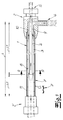
- the figures show a motor vehicle fluid line according to the invention for the passage of at least one fluid medium and preferably for the passage of a urea solution for an SCR catalyst system.
- the fluid line according to the invention has a fluid-carrying pipeline 1 and a fluid-conducting connector 2 connected to this pipeline 1.
- a connector 2 'or a second connector 2' is also connected to the other end of the pipeline 1.
- the pipeline 1 Via a part L1 of its length L, the pipeline 1 has a fluid-carrying outer conduit 3 and a fluid-carrying inner conduit 4, which is accommodated in the outer conduit 3 and runs along the outer conduit 3.
- the outer line 3 is arranged parallel to the inner line 4 and outer line 3 and inner line 4 are preferably arranged coaxially to one another.
- the pipe 1 is according to a preferred embodiment and in the embodiment of a second part of their L2 Length L is formed only in the form of a single fluid channel 11. Here, therefore, surrounds the pipe wall of the pipe 1 only a non-subdivided fluid channel eleventh
- the outer pipe 3 and the inner pipe 4 by a fluid medium - preferably flows through in the same direction - preferably urea solution.
- This flow direction is in both the outer conduit 3 and in the inner conduit 4 in the Fig. 1 indicated by arrows.
- the fluid medium or the urea solution thus flows toward the connector 2.
- the pipe 1 is connected directly to the fluid-carrying connector 2 and that preferably and in the embodiment, a material fit connected to the connector 2. It is recommended, and in the embodiment, both the outer line 3 and the inner line cohesively connected to the connector 2.
- the outer pipe 3 and the inner pipe 4 are preferably connected to the connector 2 via a spin welding connection or a laser welding joint.
- the pipe 1 is formed heated. It is recommended, and in the exemplary embodiment, the outer line 3 surrounded by an electrically heatable heating wire 8. Thus, only the outer line 3 is provided with a heating means or with a heating wire 8 and it is within the scope of the invention that by this heating and the fluid medium in the inner pipe 4 can be sufficiently tempered.
- the pipeline 1 is surrounded by a protective tube 7, wherein this protective tube 7 and in the embodiment is designed as a corrugated tube.
- the connector 2 has two parallel fluid channels 9, 10, which preferably and in the exemplary embodiment form a linear extension of the outer line 3 and the inner line 4.
- the inner fluid passage 9 corresponds to a linear extension of the inner conduit 4 and the outer fluid passage 10 of a linear extension of the outer conduit 3, wherein the outer fluid passage 10 surrounds the inner fluid passage 9 of the connector 2.
- the two fluid channels 9, 10 of the connector 2 are arranged coaxially with each other.
- Each of the two fluid channels 9, 10 is preferred and in the exemplary embodiment connected to a connection branch 5, 6 of the connector 2.
- connection branch 6 is arranged transversely or perpendicular to the longitudinal axis of the pipeline 1 or to the longitudinal axis of the connector 2.
- This connection branch 6 is expediently and in the exemplary embodiment connected to the outer fluid channel 10.
- Another connection branch 5 forms a linear extension of the inner line 4 and the inner fluid channel 9.
- the two horridsaliteige 5, 6 of the connector 2 are each connected to a metering device, not shown in the figures for a metered feeding of the fluid medium.
- a metering device for an SCR catalyst system.
- the metering devices are preferably arranged at different locations of the SCR catalyst system or the associated motor vehicle.
Landscapes
- Engineering & Computer Science (AREA)
- General Engineering & Computer Science (AREA)
- Mechanical Engineering (AREA)
- Chemical & Material Sciences (AREA)
- Chemical Kinetics & Catalysis (AREA)
- Health & Medical Sciences (AREA)
- Toxicology (AREA)
- Combustion & Propulsion (AREA)
- Exhaust Gas After Treatment (AREA)
- Resistance Heating (AREA)
- Pipe Accessories (AREA)
- Exhaust Gas Treatment By Means Of Catalyst (AREA)
Abstract
Description
- Die Erfindung betrifft eine Kraftfahrzeug-Fluidleitung zur Durchleitung zumindest eines fluiden Mediums, insbesondere zur Durchleitung von Harnstofflösungen für SCR-Katalysatorsysteme, wobei zumindest eine fluidführende Rohrleitung sowie zumindest ein an die Rohrleitung angeschlossener fluidführender Verbinder vorgesehen ist. - Es liegt im Rahmen der Erfindung, dass der Verbinder zumindest zwei Verbindungsabzweige aufweist, durch die das fluide Medium - insbesondere die Harnstofflösung - abgeführt bzw. weitergeführt wird. Zweckmäßigerweise wird das fluide Medium über zumindest einen Verbindungsabzweig zu einem Aggregat geleitet, wobei es sich bei dem Aggregat bevorzugt um eine Dosiereinrichtung handelt. Mit der Dosiereinrichtung ist ein dosiertes Zuführen des fluiden Mediums möglich und zwar nach empfohlener Ausführungsform eine dosierte Zuführung des fluiden Mediums bzw. der Harnstoffleitung zu einem SCR-Katalysatorsytem. In Kraftfahrzeugen - insbesondere in Fahrzeugen mit Dieselmotor - ist in der Regel ein SCR-Katalysatorsystem mit einem SCR-Katalysator für die Abgasbehandlung vorhanden (SCR: Selective Catalytic Reduction). Für eine effektive Reduzierung der im Abgas eines Kraftfahrzeuges enthaltenen Stickoxide wird dem Abgas vor einem SCR-Katalysator eine Harnstofflösung zudosiert.
- Kraftfahrzeug-Fluidleitungen der eingangs genannten Art sind aus der Praxis in unterschiedlichen Ausführungsformen bekannt und zwar insbesondere auch bekannt im Zusammenhang mit der Durchleitung von Harnstofflösungen für SCR-Katalysatorsysteme. Dabei kann der an die Rohrleitung angeschlossene Verbinder zwei Verbindungsabzweige für die Harnstofflösung aufweisen, wobei die Harnstofflösung über diese Verbindungsabzweige jeweils einer Dosiereinrichtung für ein dosiertes Zuführen der Harnstofflösung zu einem SCR-Katalysatorsystem zugeleitet wird. Die Rohrleitung weist dabei einen einzigen Innenkanal auf, der von der Rohrleitungswandung umgeben ist. Aus dem Innenkanal der Rohrleitung tritt das fluide Medium bzw. tritt die Harnstofflösung in die beiden Verbindungsabzweige des Verbinders ein. - Beim Abschalten des Motors eines Kraftfahrzeuges mit einem solchen SCR-Katalysatorsystem wird das SCR-System - insbesondere die Rohrleitung und der Verbinder - entleert bzw. von der Harnstofflösung befreit. Wenn dann später das System wieder mit Harnstofflösung gefüllt wird treten insbesondere im Bereich des Verbinders und im Bereich der Verbindungsabzweige in der Flüssigkeitsströmung Wirbel und/oder Blasen auf, die eine gleichmäßige Strömung der Harnstofflösung stören und somit zur Beeinträchtigung des gesamten SCR-Systems führen können.
- Der Erfindung liegt das technische Problem zugrunde, eine Kraftfahrzeug-Fluidleitung der eingangs beschriebenen Art anzugeben, bei der diese Nachteile vermieden werden können.
- Zur Lösung dieses technischen Problems lehrt die Erfindung eine Kraftfahrzeug-Fluidleitung zur Durchleitung zumindest eines fluiden Mediums, insbesondere zur Durchleitung von Harnstofflösungen für SCR-Katalysatorsysteme, wobei zumindest eine fluidführende Rohrleitung sowie zumindest ein an die Rohrleitung angeschlossener fluidführender Verbinder vorgesehen ist, wobei die Rohrleitung über zumindest einen Teil ihrer Länge L eine fluidführende Außenleitung sowie eine in der Außenleitung aufgenommene, längs der Außenleitung verlaufende fluidführende Innenleitung aufweist und wobei der Verbinder zumindest einen bzw. einen ersten Verbindungsabzweig aufweist, der in Fluidverbindung mit der Außenleitung steht sowie zumindest einen bzw. einen zweiten Verbindungsabzweig aufweist, der in Fluidverbindung mit der Innenleitung steht.
- Gemäß besonders empfohlener Ausführungsform der Erfindung besteht die Rohrleitung bzw. die Außenleitung und/oder die Innenleitung aus Kunststoff bzw. im Wesentlichen aus Kunststoff. Zweckmäßigerweise besteht der an die Rohrleitung angeschlossene Verbinder aus Kunststoff bzw. im Wesentlichen aus Kunststoff.
- Es liegt im Rahmen der Erfindung, dass die Rohrleitung unmittelbar an dem fluidführenden Verbinder angeschlossen ist. Eine bevorzugte Ausführungsform der Erfindung ist dadurch gekennzeichnet, dass die Außenleitung und/oder die Innenleitung stoffschlüssig mit dem Verbinder verbunden ist/sind. Eine sehr bevorzugte Ausführungsform der Erfindung zeichnet sich in diesem Zusammenhang dadurch aus, dass die Außenleitung und/oder die Innenleitung über eine Rotationsschweißverbindung und/oder über eine Laserschweißverbindung mit dem Verbinder verbunden ist/sind.
- Der Erfindung liegt die Erkenntnis zugrunde, dass durch die erfindungsgemäße Aufteilung der Rohrleitung in eine fluidführende Außenleitung und eine fluidführende Innenleitung ungleichmäßige Strömungsverhältnisse im Verbinder und insbesondere im Bereich der beiden Verbindungsabzweige auf ein Minimum reduziert werden können bzw. quasi vermieden werden können. Das gilt vor allem auch für einen Befüllvorgang der erfindungsgemäßen Kraftfahrzeug-Fluidleitung mit einem fluiden Medium bzw. mit einer Harnstofflösung. Im Gegensatz zu den aus der Praxis bekannten Fluidleitungen kann dabei vor allem im Bereich des Verbinders eine sehr gleichmäßige Strömung des fluiden Mediums insbesondere im Übergangsbereich zwischen der Rohrleitung und den Verbindungsabzweigen beobachtet werden. Besondere Bedeutung kommt in diesem Zusammenhang auch der Ausführungsform zu, wonach sowohl die Außenleitung als auch die Innenleitung und der Verbinder aus Kunststoff bzw. im Wesentlichen aus Kunststoff bestehen und wobei die Außenleitung und die Innenleitung stoffschlüssig mit dem Verbinder verbunden sind bzw. bevorzugt über eine Rotationsschweißverbindung oder eine Laserschweißverbindung mit dem Verbinder verbunden sind. Diese Verbindungsart trägt überraschenderweise zu einer Vergleichmäßigung der Strömung im Bereich des Verbinders bzw. im Bereich der Verbindungsabzweige bei.
- Es liegt im Rahmen der Erfindung, dass die Außenleitung der Rohrleitung parallel bzw. im Wesentlichen parallel zur Innenleitung der Rohrleitung angeordnet ist. Gemäß besonders bevorzugter Ausführungsform der erfindungsgemäßen Fluidleitung sind die Außenleitung und die Innenleitung koaxial bzw. im Wesentlichen koaxial zueinander angeordnet. Es liegt im Rahmen der Erfindung, dass die Querschnitte von Außenleitung und Innenleitung konzentrisch angeordnet sind bzw. konzentrisch zueinander angeordnet sind. Diese koaxiale bzw. konzentrische Anordnung von Außenleitung und Innenleitung bringt den Vorteil mit sich, dass das fluide Medium bzw. die Harnstofflösung sowohl in der Außenleitung als auch in der Innenleitung - bei einer bevorzugten Beheizung der Rohrleitung --sehr gleichmäßig beheizt werden kann. Zusätzlich trägt diese Ausgestaltung zu gleichmäßigen Strömungsverhältnissen an den beiden Verbindungsabzweigen bei.
- Erfindungsgemäß weist die Rohrleitung über zumindest einen Teil ihrer Länge L die fluidführende Außenleitung und die in der Außenleitung aufgenommene fluidführende Innenleitung auf. Dabei liegt es im Rahmen der Erfindung, dass die Rohrleitung in ihrem an den Verbinder mit den beiden Verbindungsabzweigen angeschlossenen Bereich in Form der Außenleitung und der Innenleitung ausgebildet ist. Nach einer Ausführungsform der Erfindung ist die Rohrleitung über zumindest 50 % ihrer Länge L, vorzugsweise über zumindest 60 % ihrer Länge L und bevorzugt über zumindest 70 % ihrer Länge L in Form der Außenleitung und der Innenleitung ausgebildet. Es liegt im Rahmen der Erfindung, dass die Rohrleitung über einen Teil ihrer Länge L lediglich in Form eines einzigen Fluidkanals ausgebildet ist. In diesem Teil ihrer Länge L weist die Rohrleitung also nur einen Innenkanal bzw. Fluidkanal auf, der von der Rohrleitungswandung umgeben wird. Es liegt weiterhin im Rahmen der Erfindung, dass dieser Teil der Rohrleitung mit dem einzigen Fluidkanal unmittelbar in den Abschnitt der Rohrleitung mit der Außenleitung und der Innenleitung übergeht. Dabei ragt die Innenleitung also gleichsam in den Fluidkanal bzw. Innenkanal der Rohrleitung hinein. Es wurde bereits oben darauf hingewiesen, dass nach bevorzugter Ausführungsform in dem Rohrleitungsabschnitt mit Außenleitung und Innenleitung die beiden Leitungen bzw. Außenleitung und Innenleitung koaxial bzw. im Wesentlichen koaxial zueinander angeordnet sind.
- Es liegt im Rahmen der Erfindung, dass die Außenleitung und die Innenleitung von dem fluiden Medium - insbesondere von der Harnstofflösung - in der gleichen Richtung durchströmt werden und zwar zweckmäßigerweise in Richtung des Verbinders mit den zumindest zwei Verbindungsabzweigen. Insofern unterscheidet sich die erfindungsgemäße Fluidleitung von an sich aus der Praxis bekannten Fluidleitungen, bei denen zwei zueinander parallele Rohrleitungen bzw. zueinander koaxiale Rohrleitungen im Gegenstrom von einem fluiden Medium durchströmt werden. Bei diesen aus der Praxis bekannten Rohrleitungen dient ein durch eine Außenleitung geleitetes fluides Medium der Temperierung des durch eine Innenleitung geleiteten fluiden Mediums oder umgekehrt. Im Rahmen der Erfindung ist eine gezielte Temperierung lediglich durch ein in der Außenleitung und/oder in der Innenleitung strömendes fluides Medium vorzugsweise nicht vorgesehen. Es liegt somit im Rahmen der Erfindung, dass sowohl die Außenleitung als auch die Innenleitung temperiermediumfrei von einem fluiden Medium durchströmt werden. Eine bevorzugte Ausführungsform einer Temperierung bzw. Beheizung der erfindungsgemäßen Fluidleitung bzw. von deren Rohrleitung wird nachfolgend beschrieben.
- Nach einer empfohlenen Ausführungsform der Erfindung wird die Rohrleitung über zumindest einen Teil ihrer Länge L, vorzugsweise über ihre gesamte Länge L bzw. im Wesentlichen über ihre gesamte Länge L beheizt. Die bevorzugte Beheizung der erfindungsgemäßen Fluidleitung bzw. die Beheizung der Rohrleitung wird insbesondere dann vorgenommen, wenn es sich bei dem durchströmenden fluiden Medium um eine Harnstofflösung bzw. eine wässrige Harnstofflösung für ein SCR-Katalysatorsystem handelt. Eine solche Harnstofflösung bzw. wässrige Harnstofflösung hat den Nachteil, dass Harnstoff bei Temperaturen unter -11°C gefriert und teilweise auskristallisiert. Dadurch wird eine weitere funktionssichere Zufuhr der Harnstofflösung behindert oder vollständig blockiert. Folglich wird eine effektive Reduzierung der Stickoxide im Abgas des betreffenden Kraftfahrzeuges beeinträchtigt bzw. verhindert. Um diesen Nachteil zu vermeiden ist eine Beheizung der die Harnstofflösung führenden Rohrleitung zweckmäßig.
- Gemäß besonders empfohlener Ausführungsform der erfindungsgemäßen Fluidleitung weist die Außenleitung zumindest ein Heizmittel, vorzugsweise zumindest einen Heizdraht auf. Zweckmäßigerweise ist die Außenleitung von diesem Heizmittel bzw. von dem zumindest einen Heizdraht umgeben. Es empfiehlt sich, dass zumindest ein Heizdraht wendeiförmig bzw. spiralförmig um die Außenleitung gewickelt ist. Über diesen zumindest einen Heizdraht erfolgt zweckmäßigerweise eine elektrische Beheizung und dazu ist der Heizdraht an eine Stromquelle angeschlossen. Gemäß einer weiteren Ausführungsvariante der Erfindung kann die Beheizung der Rohrleitung über zumindest ein elektrisch beheiztes flächiges Heizmittel erfolgen, insbesondere durch eine elektrisch beheizte Heizfolie, durch ein elektrisch beheiztes flächiges Heizband oder durch aufgedruckte Heizstrukturen. Das flächige Heizmittel ist dann zweckmäßigerweise um die Außenleitung der Rohrleitung gewickelt. Der Erfindung liegt insoweit die Erkenntnis zugrunde, dass bei einer erfindungsgemäßen Aufteilung der Rohrleitung in Außenleitung und Innenleitung eine Beheizung der Außenleitung mittels zumindest eines Heizmittels bzw. mittels zumindest eines elektrischen Heizdrahtes oder flächigen Heizmittels ausreichend ist. Dadurch kann auch die durch die Innenleitung geführte Harnstofflösung hinreichend temperiert werden um ein Einfrieren zu vermeiden.
- Gemäß einer bewährten Ausführungsform der Erfindung wird auch der an die Außenleitung und die Innenleitung angeschlossene Verbinder beheizt, bevorzugt elektrisch beheizt. Zweckmäßigerweise ist auch hier zumindest ein Heizmittel bzw. elektrisch beheizbares Heizmittel um den Verbinder gewickelt. Es ist aber auch möglich, dass der Verbinder kein eigenes Heizmittel aufweist.
- Eine bevorzugte Ausführungsform der erfindungsgemäßen Kraftfahrzeug-Fluidleitung ist dadurch gekennzeichnet, dass die Rohrleitung von einem Schutzrohr umgeben ist. Dabei sind Rohrleitung und Schutzrohr zweckmäßigerweise koaxial bzw. im Wesentlichen koaxial zueinander angeordnet. Eine beispielhafte Ausführungsform der Erfindung zeichnet sich dadurch aus, dass das die Rohrleitung umgebende Schutzrohr als Wellrohr ausgebildet ist. Nach bewährter Ausführungsform der Erfindung umgibt das Schutzrohr die Außenleitung und die Außenleitung umgibt wiederum die Innenleitung. Schutzrohr, Außenleitung und Innenleitung sind dann bevorzugt koaxial bzw. im Wesentlichen koaxial zueinander angeordnet. Es liegt im Rahmen der Erfindung, dass Schutzrohr, Außenleitung und Innenleitung im Schnitt konzentrisch zueinander orientiert sind.
- Eine besonders empfohlene Ausführungsform der Erfindung ist dadurch gekennzeichnet, dass der Verbinder zumindest zwei Fluidkanäle und bevorzugt zumindest zwei zueinander parallele bzw. im Wesentlichen parallele Fluidkanäle aufweist, welche Fluidkanäle jeweils an einen Verbindungsabzweig des Verbinders angeschlossen sind. Es liegt im Rahmen der Erfindung, dass die beiden Fluidkanäle gleichsam die Verlängerung der Außenleitung und der Innenleitung der Rohrleitung bilden und zweckmäßigerweise als lineare Verlängerung von Außenleitung und Innenleitung ausgestaltet sind. Vorzugsweise sind auch die Fluidkanäle des Verbinders als Außen-Fluidkanal und Innen-Fluidkanal ausgebildet, wobei der Außen-Fluidkanal den Innen-Fluidkanal umgibt. Empfohlenermaßen sind die beiden Fluidkanäle (Außen-Fluidkanal und Innen-Fluidkanal) koaxial zueinander angeordnet. Die Fluidkanäle (Innen-Fluidkanal und Außen-Fluidkanal) sind gemäß empfohlener Ausführungsform der Erfindung unmittelbar an die Verbindungsabzweige des Verbinders angeschlossen. Nach einer Ausführungsvariante ist zumindest ein bzw. ein Verbindungsabzweig des Verbinders quer und vorzugsweise senkrecht zur Längsachse der Rohrleitung und zur Längsachse des Verbinders orientiert. Empfohlenermaßen ist zumindest ein bzw. ein Verbindungsabzweig des Verbinders als lineare Verlängerung der Rohrleitung bzw. eines Fluidkanals des Verbinders ausgebildet. Zweckmäßigerweise handelt es sich dabei um den an den Innen-Fluidkanal des Verbinders angeschlossenen Verbindungsabzweig. Vorzugsweise ist an den Außen-Fluidkanal des Verbinders ein Verbindungsabzweig angeschlossen, der quer bzw. senkrecht zur Längsachse der Rohrleitung und zur Längsachse des Verbinders angeordnet ist.
- Es liegt im Rahmen der Erfindung, dass an jedem Verbindungsabzweig des Verbinders bzw. an beiden Verbindungsabzweigen des Verbinders eine Dosiereinrichtung für eine dosierte Zuführung des fluiden Mediums angeschlossen ist. Gemäß besonders bevorzugter Ausführungsformen der Erfindung ist an jeden Verbindungsabzweig des Verbinders eine Dosiereinrichtung eines SCR-Katalysatorsystems für ein dosiertes Zuführen von Harnstofflösung vorgesehen. Dabei ist zweckmäßigerweise zumindest eine Dosiereinrichtung im Motorraum des zugeordneten Kraftfahrzeuges angeordnet.
- Gegenstand der Erfindung ist auch ein Verfahren zur Herstellung einer Kraftfahrzeug-Fluidleitung, wobei ein Verbinder mit einer Innenleitung stoffschlüssig verbunden wird, wobei das Aggregat aus Verbinder und Innenleitung anschließend an die Außenleitung angeschlossen wird, indem die Innenleitung in die Außenleitung eingeführt bzw. eingeschoben wird und die Außenleitung danach stoffschlüssig mit dem Verbinder verbunden wird. Es liegt im Rahmen der Erfindung, dass die Innenleitung und/oder die Außenleitung aus Kunststoff bestehen bzw. im Wesentlichen aus Kunststoff bestehen. Weiterhin liegt es im Rahmen der Erfindung, dass die Innenleitung und/oder die Außenleitung durch Extrusion hergestellt wird/werden. Nach bevorzugter Ausführungsform der Erfindung wird an die Außenleitung vor ihrer Verbindung mit dem Aggregat aus Verbinder und Innenleitung ein zweiter Verbinder angeschlossen, wobei dieser zweite Verbinder bevorzugt ebenfalls stoffschlüssig mit der Außenleitung verbunden wird. Anschließend werden dann die beiden Aggregate aus dem ersten Verbinder und der Innenleitung und aus dem zweiten Verbinder und der Außenleitung so miteinander verbunden, dass die Innenleitung in die Außenleitung eingeführt bzw. eingeschoben wird und daraufhin die Außenleitung mit dem ersten Verbinder stoffschlüssig verbunden wird. Der erste Verbinder und/oder der zweite Verbinder sind nach empfohlener Ausführungsform der Erfindung als Schnellverbinder (sogenannte Quick-Connectoren) ausgebildet. Der erste Verbinder und/oder der zweite Verbinder werden vorzugsweise mittels eines Spritzgießverfahrens erzeugt. Wie oben bereits dargelegt zeichnet sich eine besonders bevorzugte Ausführungsform des erfindungsgemäßen Verfahrens dadurch aus, dass die Innenleitung mit dem Verbinder bzw. mit dem ersten Verbinder durch ein Rotationsschweißverfahren oder ein Laserschweißverfahren verbunden wird und/oder dass die Außenleitung mit dem Verbinder bzw. mit dem ersten Verbinder durch ein Rotationsschweißverfahren oder durch Laserschweißverfahren verbunden wird. Der Verbinder umfasst besonders bevorzugt ein lasertransparentes Material. Vorzugsweise findet auch die Verbindung zwischen der Außenleitung und dem zweiten Verbinder mittels eines Rotationsschweißverfahrens oder eines Laserschweißverfahrens statt.
- Der Erfindung liegt die Erkenntnis zugrunde, dass bei einer erfindungsgemäßen Kraftfahrzeug-Fluidleitung stets eine gleichmäßige Strömung des durchströmenden fluiden Mediums bzw. der durchströmenden Harnstofflösung aufrechterhalten werden kann und zwar ohne störende Wirbel oder Blasen in dem fluiden Medium. Das gilt insbesondere auch für die Befüllung der erfindungsgemäßen Kraftfahrzeug-Fluidleitung im Rahmen eines SCR-Katalysatorsystems. Vor allem im Anschlussbereich zwischen Rohrleitung und Verbinder können bei den erfindungsgemäßen Fluidleitungen Ungleichmäßigkeiten in der Strömung auf ein Minimum reduziert werden bzw. quasi vermieden werden. Somit können bei der erfindungsgemäßen Lösung Beeinträchtigungen des SCR-Katalysatorsystems aufgrund von Strömungsungleichmäßigkeiten weitgehend ausgeschlossen werden. Nichtsdestoweniger ist eine einfache und problemlose Beheizung bzw. elektrische Beheizung der erfindungsgemäßen Fluidleitung und auch das an Außenleitung und Innenleitung angeschlossenen Verbinders möglich. Sowohl das die Außenleitung als auch das die Innenleitung durchströmende fluide Medium kann effektiv beheizt bzw. temperiert werden. Hervorzuheben ist weiterhin, dass die erfindungsgemäße Fluidleitung mit verhältnismäßig geringem Aufwand und relativ geringen Kosten gefertigt werden kann. Zu betonen ist weiterhin, dass zu den vorstehend beschriebenen Vorteilen der erfindungsgemäßen Fluidleitung auch die bevorzugte stoffschlüssige Verbindung der Komponenten, insbesondere durch Rotationsschweißen oder Laserschweißen begünstigend beiträgt.
- Nachfolgend wird die Erfindung anhand einer lediglich ein Ausführungsbeispiel darstellenden Zeichnung näher erläutert. Es zeigen in schematischer Darstellung:
- Fig. 1
- Eine Seitenansicht der erfindungsgemäßen Kraftfahrzeug-Fluidleitung im Schnitt und
- Fig. 2
- einen Schnitt A-A durch den Gegenstand der
Fig. 1 . - Die Figuren zeigen eine erfindungsgemäße Kraftfahrzeug-Fluidleitung zur Durchleitung zumindest eines fluiden Mediums und vorzugsweise zur Durchleitung einer Harnstofflösung für ein SCR-Katalysatorsystem. Die erfindungsgemäße Fluidleitung weist im Ausführungsbeispiel eine fluidführende Rohrleitung 1 auf sowie einen an diese Rohrleitung 1 angeschlossenen fluidführenden Verbinder 2. Vorzugsweise und im Ausführungsbeispiel ist an dem anderen Ende der Rohrleitung 1 ebenfalls ein Verbinder 2' bzw. ein zweiter Verbinder 2' angeschlossen.
- Die Rohrleitung 1 weist über einen Teil L1 ihrer Länge L eine fluidführende Außenleitung 3 sowie eine in der Außenleitung 3 aufgenommene längs der Außenleitung 3 verlaufende fluidführende Innenleitung 4 auf. Zweckmäßigerweise und im Ausführungsbeispiel ist die Außenleitung 3 parallel zur Innenleitung 4 angeordnet und Außenleitung 3 und Innenleitung 4 sind bevorzugt koaxial zueinander angeordnet. Die Rohrleitung 1 ist nach bevorzugter Ausführungsform und im Ausführungsbeispiel über einen zweiten Teil L2 ihrer Länge L lediglich in Form eines einzigen Fluidkanals 11 ausgebildet. Hier umgibt also die Rohrleitungswandung der Rohrleitung 1 lediglich einen nicht unterteilten Fluidkanal 11.
- Im Ausführungsbeispiel wird die Außenleitung 3 und die Innenleitung 4 von einem fluiden Medium - vorzugsweise von Harnstofflösung - in der gleichen Richtung durchströmt. Diese Strömungsrichtung ist sowohl in der Außenleitung 3 als auch in der Innenleitung 4 in der
Fig. 1 durch Pfeile angedeutet worden. Das fluide Medium bzw. die Harnstofflösung strömt somit zu dem Verbinder 2 hin. - Nach bevorzugter Ausführungsform und im Ausführungsbeispiel ist die Rohrleitung 1 unmittelbar an den fluidführenden Verbinder 2 angeschlossen und zwar bevorzugt und im Ausführungsbeispiel stoffschlüssig an den Verbinder 2 angeschlossen. Dabei ist empfohlenermaßen und im Ausführungsbeispiel sowohl die Außenleitung 3 als auch die Innenleitung stoffschlüssig mit dem Verbinder 2 verbunden. Die Außenleitung 3 und die Innenleitung 4 sind bevorzugt über eine Rotationsschweißverbindung oder eine Laserschweißverbindung mit dem Verbinder 2 verbunden.
- Nach sehr bevorzugter Ausführungsform und im Ausführungsbeispiel ist die Rohrleitung 1 beheizt ausgebildet. Dabei ist empfohlenermaßen und im Ausführungsbeispiel die Außenleitung 3 von einem elektrisch beheizbaren Heizdraht 8 umgeben. Somit ist lediglich die Außenleitung 3 mit einem Heizmittel bzw. mit einem Heizdraht 8 versehen und es liegt im Rahmen der Erfindung, dass durch diese Beheizung auch das fluide Medium in der Innenleitung 4 ausreichend temperiert werden kann. - Zweckmäßigerweise und im Ausführungsbeispiel ist die Rohrleitung 1 von einem Schutzrohr 7 umgeben, wobei dieses Schutzrohr 7 und im Ausführungsbeispiel als Wellrohr ausgebildet ist.
- Insbesondere in der
Fig. 1 ist erkennbar, dass der Verbinder 2 zwei parallele Fluidkanäle 9, 10 aufweist, die bevorzugt und im Ausführungsbeispiel eine lineare Verlängerung der Außenleitung 3 und der Innenleitung 4 bilden. Dabei entspricht der Innen-Fluidkanal 9 einer linearen Verlängerung der Innenleitung 4 und der Außen-Fluidkanal 10 einer linearen Verlängerung der Außenleitung 3, wobei der Außen-Fluidkanal 10 den Innen-Fluidkanal 9 des Verbinders 2 umgibt. Vorzugsweise und im Ausführungsbeispiel sind die beiden Fluidkanäle 9, 10 des Verbinders 2 koaxial zueinander angeordnet. Jeder der beiden Fluidkanäle 9, 10 ist bevorzugt und im Ausführungsbeispiel an einen Verbindungsabzweig 5, 6 des Verbinders 2 angeschlossen. Ein Verbindungsabzweig 6 ist dabei im Ausführungsbeispiel quer bzw. senkrecht zur Längsachse der Rohrleitung 1 bzw. zur Längsachse des Verbinders 2 angeordnet. Dieser Verbindungsabzweig 6 ist zweckmäßigerweise und im Ausführungsbeispiel an den Außen-Fluidkanal 10 angeschlossen. Ein weiterer Verbindungsabzweig 5 bildet eine lineare Verlängerung der Innenleitung 4 und des Innen-Fluidkanals 9. - Nach bevorzugter Ausführungsform sind die beiden Verbindungsabzweige 5, 6 des Verbinders 2 jeweils an eine in den Figuren nicht dargestellte Dosiereinrichtung für ein dosiertes Zuführen des fluiden Mediums angeschlossen. Dabei handelt es sich zweckmäßigerweise jeweils um eine Dosiereinrichtung für ein SCR-Katalysatorsystem. Die Dosiereinrichtungen sind bevorzugt an verschiedenen Stellen des SCR-Katalysatorsystems bzw. des zugeordneten Kraftfahrzeuges angeordnet.
Claims (15)
- Kraftfahrzeug-Fluidleitung zur Durchleitung zumindest eines fluiden Mediums, insbesondere zur Durchleitung von Harnstofflösungen für SCR-Katalysatorsysteme, wobei zumindest eine fluidführende Rohrleitung (1) sowie zumindest ein an die Rohrleitung (1) angeschlossener fluidführender Verbinder (2) vorgesehen ist, wobei die Rohrleitung (1) über zumindest einen Teil ihrer Länge L eine fluidführende Außenleitung (3) sowie eine in der Außenleitung (3) aufgenommene, längs der Außenleitung (3) verlaufende fluidführende Innenleitung (4) aufweist und wobei der Verbinder (2) zumindest einen bzw. einen ersten Verbindungsabzweig (5) aufweist, der in Fluidverbindung mit der Außenleitung (3) steht sowie zumindest einen bzw. einen zweiten Verbindungsabzweig (6) aufweist, der in Fluidverbindung mit der Innenleitung (4) steht.
- Kraftfahrzeug-Fluidleitung nach Anspruch 1, wobei die Rohrleitung (1) unmittelbar an den fluidführenden Verbinder (2) angeschlossen ist.
- Kraftfahrzeug-Fluidleitung nach einem der Ansprüche 1 oder 2, wobei die Außenleitung (3) und/oder die Innenleitung (4) stoffschlüssig mit dem Verbinder (2) verbunden ist/sind.
- Kraftfahrzeug-Fluidleitung nach Anspruch 3, wobei die Außenleitung (3) und/oder die Innenleitung (4) über eine Rotationsschweißverbindung und/oder eine Laserschweißverbindung mit dem Verbinder (2) verbunden ist/sind.
- Kraftfahrzeug-Fluidleitung nach einem der Ansprüche 1 bis 4, wobei die Außenleitung (3) parallel bzw. im Wesentlichen parallel zur Innenleitung (4) angeordnet ist.
- Kraftfahrzeug-Fluidleitung nach einem der Ansprüche 1 bis 5, wobei die Außenleitung (3) und die Innenleitung (4) koaxial bzw. im Wesentlichen koaxial zueinander angeordnet sind.
- Kraftfahrzeug-Fluidleitung nach einem der Ansprüche 1 bis 6, wobei die Rohrleitung (1) über einen Teil ihrer Länge L lediglich in Form eines einzigen Fluidkanals (11) ausgebildet ist und wobei die Rohrleitung (1) über einen weiteren Teil ihrer Länge L in Form der Außenleitung (3) und der Innenleitung (4) ausgebildet ist.
- Kraftfahrzeug-Fluidleitung nach einem der Ansprüche 1 bis 7, wobei die Außenleitung (3) und die Innenleitung (4) von einem fluiden Medium - insbesondere von der Harnstofflösung - in der gleichen Richtung durchströmbar sind bzw. durchströmt werden.
- Kraftfahrzeug-Fluidleitung nach einem der Ansprüche 1 bis 8, wobei die Rohrleitung (1) über zumindest einen Teil ihrer Länge L, vorzugsweise über ihre gesamte Länge L beheizt ausgebildet ist.
- Kraftfahrzeug-Fluidleitung nach einem der Ansprüche 1 bis 9, wobei die Außenleitung (3) zumindest ein Heizmittel aufweist und vorzugsweise von zumindest einem Heizmittel umgeben ist.
- Kraftfahrzeug-Fluidleitung nach Anspruch 10, wobei das zumindest eine Heizmittel in Form eines Heizdrahtes (8) und/oder in Form eines flächigen Heizmittels ausgebildet ist.
- Kraftfahrzeug-Fluidleitung nach einem der Ansprüche 1 bis 11, wobei die Rohrleitung (1) von einem Schutzrohr (7) umgeben ist.
- Kraftfahrzeug-Fluidleitung nach einem der Ansprüche 1 bis 9, wobei der Verbinder (2) zumindest zwei parallele bzw. im Wesentlichen parallele Fluidkanäle (9,10) aufweist, welche Fluidkanäle (9,10) jeweils an einen Verbindungsabzweig (5, 6) des Verbinders (2) angeschlossen sind.
- Kraftfahrzeug-Fluidleitung nach einem der Ansprüche 1 bis 10, wobei an jedem Verbindungsabzweig (5,6) des Verbinders (2) eine Dosiereinrichtung für ein dosiertes Zuführen des fluiden Mediums vorgesehen ist.
- Verfahren zur Herstellung einer Kraftfahrzeug-Fluidleitung - insbesondere nach einem der Ansprüche 1 bis 14 -, wobei ein Verbinder (2) mit einer Innenleitung (4) stoffschlüssig verbunden wird, wobei das Aggregat aus Verbinder (2) und Innenleitung (4) anschließend an eine Außenleitung (3) angeschlossen wird, indem die Innenleitung (4) in die Außenleitung (3) eingeführt bzw. eingeschoben wird und die Außenleitung (3) danach stoffschlüssig mit dem Verbinder (2) verbunden wird.
Priority Applications (8)
| Application Number | Priority Date | Filing Date | Title |
|---|---|---|---|
| EP16181684.8A EP3276243B2 (de) | 2016-07-28 | 2016-07-28 | Kraftfahrzeug-fluidleitung |
| PCT/EP2017/064557 WO2018019469A1 (de) | 2016-07-28 | 2017-06-14 | Kraftfahrzeug-fluidleitung |
| US16/318,302 US11365841B2 (en) | 2016-07-28 | 2017-06-14 | Motor vehicle fluid line |
| JP2019504122A JP7069112B2 (ja) | 2016-07-28 | 2017-06-14 | 自動車用流体路 |
| CN201780046150.8A CN109863342B (zh) | 2016-07-28 | 2017-06-14 | 机动车辆流体管线 |
| KR1020197003551A KR102146789B1 (ko) | 2016-07-28 | 2017-06-14 | 자동차의 유체 배관 |
| MX2019001113A MX2019001113A (es) | 2016-07-28 | 2017-06-14 | Linea de fluidos para vehiculos motorizados. |
| JP2021120792A JP2021181784A (ja) | 2016-07-28 | 2021-07-21 | 自動車用流体路 |
Applications Claiming Priority (1)
| Application Number | Priority Date | Filing Date | Title |
|---|---|---|---|
| EP16181684.8A EP3276243B2 (de) | 2016-07-28 | 2016-07-28 | Kraftfahrzeug-fluidleitung |
Publications (3)
| Publication Number | Publication Date |
|---|---|
| EP3276243A1 true EP3276243A1 (de) | 2018-01-31 |
| EP3276243B1 EP3276243B1 (de) | 2018-11-28 |
| EP3276243B2 EP3276243B2 (de) | 2021-11-10 |
Family
ID=56551329
Family Applications (1)
| Application Number | Title | Priority Date | Filing Date |
|---|---|---|---|
| EP16181684.8A Active EP3276243B2 (de) | 2016-07-28 | 2016-07-28 | Kraftfahrzeug-fluidleitung |
Country Status (7)
| Country | Link |
|---|---|
| US (1) | US11365841B2 (de) |
| EP (1) | EP3276243B2 (de) |
| JP (2) | JP7069112B2 (de) |
| KR (1) | KR102146789B1 (de) |
| CN (1) | CN109863342B (de) |
| MX (1) | MX2019001113A (de) |
| WO (1) | WO2018019469A1 (de) |
Cited By (4)
| Publication number | Priority date | Publication date | Assignee | Title |
|---|---|---|---|---|
| CN108516222A (zh) * | 2018-02-28 | 2018-09-11 | 重庆荣爵摩托车有限公司 | 摩托车车架放置架 |
| CN108516223A (zh) * | 2018-02-28 | 2018-09-11 | 重庆荣爵摩托车有限公司 | 摩托车包装系统 |
| WO2019158713A1 (de) * | 2018-02-16 | 2019-08-22 | Voss Automotive Gmbh | Verbindungsanordnung zum verbinden von beheizbaren fluidleitungen |
| DE102021107069A1 (de) | 2021-03-22 | 2022-09-22 | Eugen Forschner Gmbh | Verbindungselement und verfahren zum herstellen eines verbindungselements |
Families Citing this family (3)
| Publication number | Priority date | Publication date | Assignee | Title |
|---|---|---|---|---|
| CN112259822A (zh) * | 2019-09-29 | 2021-01-22 | 蜂巢能源科技有限公司 | 冷却板套、电池模组和电池包 |
| GB201918607D0 (en) * | 2019-12-17 | 2020-01-29 | Rolls Royce Plc | Gimbals and their manufacture |
| US11603788B2 (en) | 2020-06-16 | 2023-03-14 | Cnh Industrial America Llc | Mixing conduits including swirler vanes for use within an exhaust treatment system |
Citations (3)
| Publication number | Priority date | Publication date | Assignee | Title |
|---|---|---|---|---|
| DE102006006211B3 (de) * | 2006-02-09 | 2007-09-20 | Rehau Ag + Co | Baugruppe zum Leiten und Temperieren einer Harnstoff-Wasser-Lösung und Verfahren zu deren Herstellung |
| DE202007015036U1 (de) * | 2007-10-26 | 2009-03-12 | Voss Automotive Gmbh | Leitungsverbinder sowie Leitungssatz für fluidische Medien |
| DE202011100991U1 (de) * | 2011-04-21 | 2012-08-22 | Rehau Ag + Co | Medienleitung |
Family Cites Families (33)
| Publication number | Priority date | Publication date | Assignee | Title |
|---|---|---|---|---|
| US1809714A (en) * | 1929-04-01 | 1931-06-09 | Mathews Carl Raymond | Heated water hose for filling stations |
| US2723108A (en) * | 1951-02-24 | 1955-11-08 | Diamond Alkali Co | Valve |
| US2793280A (en) * | 1954-10-06 | 1957-05-21 | Waterbury Pressed Metal Co | Electrically heated liquid connection unit |
| US3986732A (en) * | 1975-03-24 | 1976-10-19 | The Goodyear Tire & Rubber Company | Dual concentric vapor recovery fuel hose and end fitting therefor |
| JPS51133011U (de) * | 1975-04-18 | 1976-10-26 | ||
| JPS5336714U (de) | 1976-09-06 | 1978-03-31 | ||
| US4553023A (en) * | 1981-11-27 | 1985-11-12 | Nordson Corporation | Thermally insulated electrically heated hose for transmitting hot liquids |
| JP2520119B2 (ja) * | 1986-03-18 | 1996-07-31 | 名古屋アイ・イ−・シ−株式会社 | 流体の集中配送装置 |
| US5017760A (en) * | 1989-07-31 | 1991-05-21 | Gb Electrical, Inc. | Plastic pipe heater |
| US5931184A (en) * | 1997-06-10 | 1999-08-03 | Armenia; John G. | Safety hose for delivering water to an appliance |
| US5859953A (en) * | 1997-06-30 | 1999-01-12 | Nickless; Eugene R. | Electric heating apparatus for deicing pipes utilizing flexible heated hose inserted into pipe |
| JP2000027627A (ja) * | 1998-07-13 | 2000-01-25 | Hino Motors Ltd | 排気ガス浄化触媒用還元剤保温装置及びそれを組込んだ排気ガス浄化装置 |
| US6112545A (en) * | 1999-04-30 | 2000-09-05 | Taco, Inc. | Single pipe closed loop reverse flow cooling and dehumidification system |
| SE528060C2 (sv) * | 2004-02-25 | 2006-08-22 | Volvo Lastvagnar Ab | Elektriskt uppvärmningsbart kablage |
| JP2005325691A (ja) * | 2004-05-12 | 2005-11-24 | Hino Motors Ltd | 尿素水供給管 |
| FR2900217A1 (fr) | 2006-04-25 | 2007-10-26 | Nobel Plastiques Soc Par Actio | Tuyau de transport de fluide a organe compressible de compensation et troncon de circuit de transport de fluide. |
| DE202007018089U1 (de) * | 2007-12-21 | 2009-05-07 | Voss Automotive Gmbh | Beheizbare Medienleitung |
| WO2009080501A1 (de) * | 2007-12-21 | 2009-07-02 | Voss Automotive Gmbh | Leitungsverbinder für medienleitungen sowie konfektionierte medienleitung mit mindestens einem solchen leitungsverbinder |
| JP5185679B2 (ja) * | 2008-04-01 | 2013-04-17 | ニッタ株式会社 | 液体移送用チューブ |
| DE102008055060A1 (de) * | 2008-12-22 | 2010-06-24 | Robert Bosch Gmbh | Dosiermodul für ein flüssiges Reduktionsmittel |
| DE102010053737A1 (de) * | 2010-12-08 | 2012-06-14 | Voss Automotive Gmbh | Beheizbare Fluidleitung, deren Verwendung sowie Verfahren zu ihrer Herstellung |
| DE102010055520B4 (de) * | 2010-12-22 | 2023-10-05 | Voss Automotive Gmbh | Konfektionierte Medienleitung sowie Verwendung in einem SCR-Katalysator-System |
| DE202011106751U1 (de) * | 2011-10-14 | 2013-01-18 | Voss Automotive Gmbh | Zumindest teilweise beheizbarer Leitungsverbinder für eine beheizbare Medienleitung sowie konfektionierte Medienleitung mit einem solchen Leitungsverbinder |
| EP2653770B1 (de) * | 2012-04-20 | 2018-07-25 | TI Automotive (Heidelberg) GmbH | Verbinder, insbesondere Schnellverbinder |
| DE102013106217A1 (de) | 2013-06-14 | 2014-12-18 | Voss Automotive Gmbh | Leitungsverbinder sowie Leitungssatz für fluidische Medien |
| DE102014005817A1 (de) * | 2014-04-24 | 2015-10-29 | Voss Automotive Gmbh | Mehrteilige beheizbare Medienleitung, Leitungsverbindungseinrichtung für eine solche sowie Verfahren zum Herstellen einer solchen |
| JP6477250B2 (ja) * | 2014-06-12 | 2019-03-06 | トヨタ自動車株式会社 | 尿素水供給システム |
| DE102014111458A1 (de) * | 2014-08-12 | 2016-02-18 | Norma Germany Gmbh | Fluidleitung |
| DE102017123606A1 (de) * | 2017-10-11 | 2019-04-11 | Norma Germany Gmbh | Verbinder |
| DE102018103571A1 (de) | 2018-02-16 | 2019-08-22 | Voss Automotive Gmbh | Verbindungsanordnung zum Verbinden von beheizbaren Fluidleitungen |
| CN108516222B (zh) | 2018-02-28 | 2019-08-06 | 重庆荣爵摩托车有限公司 | 摩托车车架放置架 |
| CN108516223B (zh) | 2018-02-28 | 2019-07-30 | 重庆荣爵摩托车有限公司 | 摩托车包装系统 |
| CN112259822A (zh) | 2019-09-29 | 2021-01-22 | 蜂巢能源科技有限公司 | 冷却板套、电池模组和电池包 |
-
2016
- 2016-07-28 EP EP16181684.8A patent/EP3276243B2/de active Active
-
2017
- 2017-06-14 WO PCT/EP2017/064557 patent/WO2018019469A1/de not_active Ceased
- 2017-06-14 CN CN201780046150.8A patent/CN109863342B/zh active Active
- 2017-06-14 JP JP2019504122A patent/JP7069112B2/ja active Active
- 2017-06-14 US US16/318,302 patent/US11365841B2/en active Active
- 2017-06-14 KR KR1020197003551A patent/KR102146789B1/ko active Active
- 2017-06-14 MX MX2019001113A patent/MX2019001113A/es unknown
-
2021
- 2021-07-21 JP JP2021120792A patent/JP2021181784A/ja active Pending
Patent Citations (3)
| Publication number | Priority date | Publication date | Assignee | Title |
|---|---|---|---|---|
| DE102006006211B3 (de) * | 2006-02-09 | 2007-09-20 | Rehau Ag + Co | Baugruppe zum Leiten und Temperieren einer Harnstoff-Wasser-Lösung und Verfahren zu deren Herstellung |
| DE202007015036U1 (de) * | 2007-10-26 | 2009-03-12 | Voss Automotive Gmbh | Leitungsverbinder sowie Leitungssatz für fluidische Medien |
| DE202011100991U1 (de) * | 2011-04-21 | 2012-08-22 | Rehau Ag + Co | Medienleitung |
Cited By (9)
| Publication number | Priority date | Publication date | Assignee | Title |
|---|---|---|---|---|
| WO2019158713A1 (de) * | 2018-02-16 | 2019-08-22 | Voss Automotive Gmbh | Verbindungsanordnung zum verbinden von beheizbaren fluidleitungen |
| KR20200121804A (ko) * | 2018-02-16 | 2020-10-26 | 보스 오토모티브 게임베하 | 가열 가능한 유체 라인을 연결하기 위한 연결 조립체 |
| KR102467977B1 (ko) | 2018-02-16 | 2022-11-16 | 보스 오토모티브 게임베하 | 가열 가능한 유체 라인을 연결하기 위한 연결 조립체 |
| US12241579B2 (en) | 2018-02-16 | 2025-03-04 | Voss Automotive Gmbh | Connector arrangement for connecting heatable fluid lines |
| CN108516222A (zh) * | 2018-02-28 | 2018-09-11 | 重庆荣爵摩托车有限公司 | 摩托车车架放置架 |
| CN108516223A (zh) * | 2018-02-28 | 2018-09-11 | 重庆荣爵摩托车有限公司 | 摩托车包装系统 |
| CN108516223B (zh) * | 2018-02-28 | 2019-07-30 | 重庆荣爵摩托车有限公司 | 摩托车包装系统 |
| DE102021107069A1 (de) | 2021-03-22 | 2022-09-22 | Eugen Forschner Gmbh | Verbindungselement und verfahren zum herstellen eines verbindungselements |
| DE102021107069B4 (de) | 2021-03-22 | 2023-08-31 | Eugen Forschner Gmbh | Verbindungselement und Verfahren zum Herstellen eines Verbindungselements |
Also Published As
| Publication number | Publication date |
|---|---|
| JP2019529764A (ja) | 2019-10-17 |
| US11365841B2 (en) | 2022-06-21 |
| KR20190022878A (ko) | 2019-03-06 |
| US20190242512A1 (en) | 2019-08-08 |
| JP2021181784A (ja) | 2021-11-25 |
| WO2018019469A1 (de) | 2018-02-01 |
| MX2019001113A (es) | 2019-06-10 |
| EP3276243B1 (de) | 2018-11-28 |
| CN109863342A (zh) | 2019-06-07 |
| KR102146789B1 (ko) | 2020-08-24 |
| CN109863342B (zh) | 2021-07-20 |
| JP7069112B2 (ja) | 2022-05-17 |
| EP3276243B2 (de) | 2021-11-10 |
Similar Documents
| Publication | Publication Date | Title |
|---|---|---|
| EP3276243B1 (de) | Kraftfahrzeug-fluidleitung | |
| EP2653770B1 (de) | Verbinder, insbesondere Schnellverbinder | |
| EP3008371B1 (de) | Leitungsverbinder sowie leitungssatz für fluidische medien | |
| EP2655950B1 (de) | Konfektionierte medienleitung sowie verwendung in einem scr-katalysator-system | |
| EP2653765B1 (de) | Rohrleitung für ein zu temperierendes fluides Medium | |
| EP1519098A1 (de) | Elektrisch beheizbare Flüssigkeitsleitung | |
| EP3495707B1 (de) | Fluidleitung, verwendung einer solchen zum transport einer harnstofflösung und verfahren zur vermeidung des risikos einer beschädigung einer einspritzanordnung eines dieselmotors durch einfrierende harnstofflösung | |
| DE102012108273A1 (de) | Kunststofftank für eine Betriebsflüssigkeit | |
| WO2012143135A2 (de) | Medienleitung | |
| EP2414646B1 (de) | Einspritzeinrichtung für harnstoffwasserlösung | |
| EP2801743B1 (de) | Verfahren zur Verbindung eines Leitungsverbinders mit einer fluidführenden Kraftfahrzeugleitung | |
| DE102009040930B4 (de) | Heizbarer Flüssigkeitsbehälter aus Kunststoffmaterial und Verfahren zu seiner Herstellung | |
| EP1770251B1 (de) | Beheizbarer Schlauchleitungsmodul für Abgasnachbehandlungsanlagen von Brennkraftmaschinen | |
| EP3467279B1 (de) | Abgasnachbehandlungssystem für verbrennungsmotoren | |
| EP2666985A1 (de) | Beheizbare Medienleitung | |
| EP2662606B1 (de) | Schutzrohr für eine zu temperierende Medienleitung und Leitungsaggregat | |
| DE20320585U1 (de) | Elektrisch beheizbare Flüssigkeitsleitung | |
| DE102017128658B4 (de) | Leitungssystem für ein Fluid führende Leitungen | |
| EP2667075B1 (de) | Aggregat aus einem Verbinder und einer Medienleitung | |
| EP3133329B1 (de) | Beheizbare kraftfahrzeugrohrleitung und verfahren zur herstellung einer beheizbaren kraftfahrzeugrohrleitung | |
| EP2876273B1 (de) | Verbindungsaggregat aus einer beheizbaren Kraftfahrzeugleitung und einem beheizbaren Verbinder | |
| DE102014210003A1 (de) | Heizvorrichtung mit Filtrationsfunktion | |
| DE102016206244A1 (de) | System zum Fördern und Dosieren eines Reduktionsmittels zum Einbringen des Reduktionsmittels in einen Abgasstrang eines Kraftfahrzeugs |
Legal Events
| Date | Code | Title | Description |
|---|---|---|---|
| PUAI | Public reference made under article 153(3) epc to a published international application that has entered the european phase |
Free format text: ORIGINAL CODE: 0009012 |
|
| STAA | Information on the status of an ep patent application or granted ep patent |
Free format text: STATUS: REQUEST FOR EXAMINATION WAS MADE |
|
| 17P | Request for examination filed |
Effective date: 20170420 |
|
| AK | Designated contracting states |
Kind code of ref document: A1 Designated state(s): AL AT BE BG CH CY CZ DE DK EE ES FI FR GB GR HR HU IE IS IT LI LT LU LV MC MK MT NL NO PL PT RO RS SE SI SK SM TR |
|
| AX | Request for extension of the european patent |
Extension state: BA ME |
|
| GRAP | Despatch of communication of intention to grant a patent |
Free format text: ORIGINAL CODE: EPIDOSNIGR1 |
|
| STAA | Information on the status of an ep patent application or granted ep patent |
Free format text: STATUS: GRANT OF PATENT IS INTENDED |
|
| RIC1 | Information provided on ipc code assigned before grant |
Ipc: F16L 53/38 20180101ALI20180423BHEP Ipc: F16L 53/00 20180101ALI20180423BHEP Ipc: F16L 41/02 20060101AFI20180423BHEP |
|
| INTG | Intention to grant announced |
Effective date: 20180517 |
|
| GRAS | Grant fee paid |
Free format text: ORIGINAL CODE: EPIDOSNIGR3 |
|
| GRAA | (expected) grant |
Free format text: ORIGINAL CODE: 0009210 |
|
| STAA | Information on the status of an ep patent application or granted ep patent |
Free format text: STATUS: THE PATENT HAS BEEN GRANTED |
|
| AK | Designated contracting states |
Kind code of ref document: B1 Designated state(s): AL AT BE BG CH CY CZ DE DK EE ES FI FR GB GR HR HU IE IS IT LI LT LU LV MC MK MT NL NO PL PT RO RS SE SI SK SM TR |
|
| REG | Reference to a national code |
Ref country code: CH Ref legal event code: EP |
|
| REG | Reference to a national code |
Ref country code: AT Ref legal event code: REF Ref document number: 1070635 Country of ref document: AT Kind code of ref document: T Effective date: 20181215 |
|
| REG | Reference to a national code |
Ref country code: DE Ref legal event code: R096 Ref document number: 502016002615 Country of ref document: DE |
|
| REG | Reference to a national code |
Ref country code: IE Ref legal event code: FG4D Free format text: LANGUAGE OF EP DOCUMENT: GERMAN |
|
| REG | Reference to a national code |
Ref country code: NL Ref legal event code: MP Effective date: 20181128 |
|
| REG | Reference to a national code |
Ref country code: LT Ref legal event code: MG4D |
|
| PG25 | Lapsed in a contracting state [announced via postgrant information from national office to epo] |
Ref country code: FI Free format text: LAPSE BECAUSE OF FAILURE TO SUBMIT A TRANSLATION OF THE DESCRIPTION OR TO PAY THE FEE WITHIN THE PRESCRIBED TIME-LIMIT Effective date: 20181128 Ref country code: IS Free format text: LAPSE BECAUSE OF FAILURE TO SUBMIT A TRANSLATION OF THE DESCRIPTION OR TO PAY THE FEE WITHIN THE PRESCRIBED TIME-LIMIT Effective date: 20190328 Ref country code: NO Free format text: LAPSE BECAUSE OF FAILURE TO SUBMIT A TRANSLATION OF THE DESCRIPTION OR TO PAY THE FEE WITHIN THE PRESCRIBED TIME-LIMIT Effective date: 20190228 Ref country code: LV Free format text: LAPSE BECAUSE OF FAILURE TO SUBMIT A TRANSLATION OF THE DESCRIPTION OR TO PAY THE FEE WITHIN THE PRESCRIBED TIME-LIMIT Effective date: 20181128 Ref country code: HR Free format text: LAPSE BECAUSE OF FAILURE TO SUBMIT A TRANSLATION OF THE DESCRIPTION OR TO PAY THE FEE WITHIN THE PRESCRIBED TIME-LIMIT Effective date: 20181128 Ref country code: BG Free format text: LAPSE BECAUSE OF FAILURE TO SUBMIT A TRANSLATION OF THE DESCRIPTION OR TO PAY THE FEE WITHIN THE PRESCRIBED TIME-LIMIT Effective date: 20190228 Ref country code: LT Free format text: LAPSE BECAUSE OF FAILURE TO SUBMIT A TRANSLATION OF THE DESCRIPTION OR TO PAY THE FEE WITHIN THE PRESCRIBED TIME-LIMIT Effective date: 20181128 Ref country code: ES Free format text: LAPSE BECAUSE OF FAILURE TO SUBMIT A TRANSLATION OF THE DESCRIPTION OR TO PAY THE FEE WITHIN THE PRESCRIBED TIME-LIMIT Effective date: 20181128 |
|
| PG25 | Lapsed in a contracting state [announced via postgrant information from national office to epo] |
Ref country code: GR Free format text: LAPSE BECAUSE OF FAILURE TO SUBMIT A TRANSLATION OF THE DESCRIPTION OR TO PAY THE FEE WITHIN THE PRESCRIBED TIME-LIMIT Effective date: 20190301 Ref country code: PT Free format text: LAPSE BECAUSE OF FAILURE TO SUBMIT A TRANSLATION OF THE DESCRIPTION OR TO PAY THE FEE WITHIN THE PRESCRIBED TIME-LIMIT Effective date: 20190328 Ref country code: RS Free format text: LAPSE BECAUSE OF FAILURE TO SUBMIT A TRANSLATION OF THE DESCRIPTION OR TO PAY THE FEE WITHIN THE PRESCRIBED TIME-LIMIT Effective date: 20181128 Ref country code: SE Free format text: LAPSE BECAUSE OF FAILURE TO SUBMIT A TRANSLATION OF THE DESCRIPTION OR TO PAY THE FEE WITHIN THE PRESCRIBED TIME-LIMIT Effective date: 20181128 Ref country code: AL Free format text: LAPSE BECAUSE OF FAILURE TO SUBMIT A TRANSLATION OF THE DESCRIPTION OR TO PAY THE FEE WITHIN THE PRESCRIBED TIME-LIMIT Effective date: 20181128 |
|
| PG25 | Lapsed in a contracting state [announced via postgrant information from national office to epo] |
Ref country code: NL Free format text: LAPSE BECAUSE OF FAILURE TO SUBMIT A TRANSLATION OF THE DESCRIPTION OR TO PAY THE FEE WITHIN THE PRESCRIBED TIME-LIMIT Effective date: 20181128 |
|
| PG25 | Lapsed in a contracting state [announced via postgrant information from national office to epo] |
Ref country code: IT Free format text: LAPSE BECAUSE OF FAILURE TO SUBMIT A TRANSLATION OF THE DESCRIPTION OR TO PAY THE FEE WITHIN THE PRESCRIBED TIME-LIMIT Effective date: 20181128 Ref country code: PL Free format text: LAPSE BECAUSE OF FAILURE TO SUBMIT A TRANSLATION OF THE DESCRIPTION OR TO PAY THE FEE WITHIN THE PRESCRIBED TIME-LIMIT Effective date: 20181128 Ref country code: CZ Free format text: LAPSE BECAUSE OF FAILURE TO SUBMIT A TRANSLATION OF THE DESCRIPTION OR TO PAY THE FEE WITHIN THE PRESCRIBED TIME-LIMIT Effective date: 20181128 Ref country code: DK Free format text: LAPSE BECAUSE OF FAILURE TO SUBMIT A TRANSLATION OF THE DESCRIPTION OR TO PAY THE FEE WITHIN THE PRESCRIBED TIME-LIMIT Effective date: 20181128 |
|
| REG | Reference to a national code |
Ref country code: DE Ref legal event code: R026 Ref document number: 502016002615 Country of ref document: DE |
|
| PG25 | Lapsed in a contracting state [announced via postgrant information from national office to epo] |
Ref country code: SM Free format text: LAPSE BECAUSE OF FAILURE TO SUBMIT A TRANSLATION OF THE DESCRIPTION OR TO PAY THE FEE WITHIN THE PRESCRIBED TIME-LIMIT Effective date: 20181128 Ref country code: EE Free format text: LAPSE BECAUSE OF FAILURE TO SUBMIT A TRANSLATION OF THE DESCRIPTION OR TO PAY THE FEE WITHIN THE PRESCRIBED TIME-LIMIT Effective date: 20181128 Ref country code: RO Free format text: LAPSE BECAUSE OF FAILURE TO SUBMIT A TRANSLATION OF THE DESCRIPTION OR TO PAY THE FEE WITHIN THE PRESCRIBED TIME-LIMIT Effective date: 20181128 Ref country code: SK Free format text: LAPSE BECAUSE OF FAILURE TO SUBMIT A TRANSLATION OF THE DESCRIPTION OR TO PAY THE FEE WITHIN THE PRESCRIBED TIME-LIMIT Effective date: 20181128 |
|
| PLBI | Opposition filed |
Free format text: ORIGINAL CODE: 0009260 |
|
| PLAX | Notice of opposition and request to file observation + time limit sent |
Free format text: ORIGINAL CODE: EPIDOSNOBS2 |
|
| 26 | Opposition filed |
Opponent name: VOSS AUTOMOTIVE GMBH Effective date: 20190826 |
|
| PLBB | Reply of patent proprietor to notice(s) of opposition received |
Free format text: ORIGINAL CODE: EPIDOSNOBS3 |
|
| PG25 | Lapsed in a contracting state [announced via postgrant information from national office to epo] |
Ref country code: MC Free format text: LAPSE BECAUSE OF FAILURE TO SUBMIT A TRANSLATION OF THE DESCRIPTION OR TO PAY THE FEE WITHIN THE PRESCRIBED TIME-LIMIT Effective date: 20181128 |
|
| REG | Reference to a national code |
Ref country code: CH Ref legal event code: PL |
|
| PG25 | Lapsed in a contracting state [announced via postgrant information from national office to epo] |
Ref country code: TR Free format text: LAPSE BECAUSE OF FAILURE TO SUBMIT A TRANSLATION OF THE DESCRIPTION OR TO PAY THE FEE WITHIN THE PRESCRIBED TIME-LIMIT Effective date: 20181128 |
|
| REG | Reference to a national code |
Ref country code: BE Ref legal event code: MM Effective date: 20190731 |
|
| PG25 | Lapsed in a contracting state [announced via postgrant information from national office to epo] |
Ref country code: LU Free format text: LAPSE BECAUSE OF NON-PAYMENT OF DUE FEES Effective date: 20190728 Ref country code: CH Free format text: LAPSE BECAUSE OF NON-PAYMENT OF DUE FEES Effective date: 20190731 Ref country code: LI Free format text: LAPSE BECAUSE OF NON-PAYMENT OF DUE FEES Effective date: 20190731 Ref country code: BE Free format text: LAPSE BECAUSE OF NON-PAYMENT OF DUE FEES Effective date: 20190731 |
|
| PG25 | Lapsed in a contracting state [announced via postgrant information from national office to epo] |
Ref country code: IE Free format text: LAPSE BECAUSE OF NON-PAYMENT OF DUE FEES Effective date: 20190728 |
|
| GBPC | Gb: european patent ceased through non-payment of renewal fee |
Effective date: 20200728 |
|
| APBM | Appeal reference recorded |
Free format text: ORIGINAL CODE: EPIDOSNREFNO |
|
| APBP | Date of receipt of notice of appeal recorded |
Free format text: ORIGINAL CODE: EPIDOSNNOA2O |
|
| PG25 | Lapsed in a contracting state [announced via postgrant information from national office to epo] |
Ref country code: GB Free format text: LAPSE BECAUSE OF NON-PAYMENT OF DUE FEES Effective date: 20200728 |
|
| APAH | Appeal reference modified |
Free format text: ORIGINAL CODE: EPIDOSCREFNO |
|
| PG25 | Lapsed in a contracting state [announced via postgrant information from national office to epo] |
Ref country code: CY Free format text: LAPSE BECAUSE OF FAILURE TO SUBMIT A TRANSLATION OF THE DESCRIPTION OR TO PAY THE FEE WITHIN THE PRESCRIBED TIME-LIMIT Effective date: 20181128 |
|
| APBU | Appeal procedure closed |
Free format text: ORIGINAL CODE: EPIDOSNNOA9O |
|
| PG25 | Lapsed in a contracting state [announced via postgrant information from national office to epo] |
Ref country code: MT Free format text: LAPSE BECAUSE OF FAILURE TO SUBMIT A TRANSLATION OF THE DESCRIPTION OR TO PAY THE FEE WITHIN THE PRESCRIBED TIME-LIMIT Effective date: 20181128 Ref country code: HU Free format text: LAPSE BECAUSE OF FAILURE TO SUBMIT A TRANSLATION OF THE DESCRIPTION OR TO PAY THE FEE WITHIN THE PRESCRIBED TIME-LIMIT; INVALID AB INITIO Effective date: 20160728 |
|
| PUAH | Patent maintained in amended form |
Free format text: ORIGINAL CODE: 0009272 |
|
| STAA | Information on the status of an ep patent application or granted ep patent |
Free format text: STATUS: PATENT MAINTAINED AS AMENDED |
|
| PG25 | Lapsed in a contracting state [announced via postgrant information from national office to epo] |
Ref country code: SI Free format text: LAPSE BECAUSE OF FAILURE TO SUBMIT A TRANSLATION OF THE DESCRIPTION OR TO PAY THE FEE WITHIN THE PRESCRIBED TIME-LIMIT Effective date: 20181128 |
|
| 27A | Patent maintained in amended form |
Effective date: 20211110 |
|
| AK | Designated contracting states |
Kind code of ref document: B2 Designated state(s): AL AT BE BG CH CY CZ DE DK EE ES FI FR GB GR HR HU IE IS IT LI LT LU LV MC MK MT NL NO PL PT RO RS SE SI SK SM TR |
|
| REG | Reference to a national code |
Ref country code: DE Ref legal event code: R102 Ref document number: 502016002615 Country of ref document: DE |
|
| PG25 | Lapsed in a contracting state [announced via postgrant information from national office to epo] |
Ref country code: MK Free format text: LAPSE BECAUSE OF FAILURE TO SUBMIT A TRANSLATION OF THE DESCRIPTION OR TO PAY THE FEE WITHIN THE PRESCRIBED TIME-LIMIT Effective date: 20181128 |
|
| REG | Reference to a national code |
Ref country code: AT Ref legal event code: MM01 Ref document number: 1070635 Country of ref document: AT Kind code of ref document: T Effective date: 20210728 |
|
| PG25 | Lapsed in a contracting state [announced via postgrant information from national office to epo] |
Ref country code: AT Free format text: LAPSE BECAUSE OF NON-PAYMENT OF DUE FEES Effective date: 20210728 |
|
| P01 | Opt-out of the competence of the unified patent court (upc) registered |
Effective date: 20230524 |
|
| PGFP | Annual fee paid to national office [announced via postgrant information from national office to epo] |
Ref country code: DE Payment date: 20250722 Year of fee payment: 10 |
|
| PGFP | Annual fee paid to national office [announced via postgrant information from national office to epo] |
Ref country code: FR Payment date: 20250722 Year of fee payment: 10 |