EP3276128A1 - Kühlbares wandelement - Google Patents
Kühlbares wandelement Download PDFInfo
- Publication number
- EP3276128A1 EP3276128A1 EP16180939.7A EP16180939A EP3276128A1 EP 3276128 A1 EP3276128 A1 EP 3276128A1 EP 16180939 A EP16180939 A EP 16180939A EP 3276128 A1 EP3276128 A1 EP 3276128A1
- Authority
- EP
- European Patent Office
- Prior art keywords
- wall element
- turbulence enhancing
- depression
- cooling
- enhancing element
- Prior art date
- Legal status (The legal status is an assumption and is not a legal conclusion. Google has not performed a legal analysis and makes no representation as to the accuracy of the status listed.)
- Withdrawn
Links
Images
Classifications
-
- F—MECHANICAL ENGINEERING; LIGHTING; HEATING; WEAPONS; BLASTING
- F01—MACHINES OR ENGINES IN GENERAL; ENGINE PLANTS IN GENERAL; STEAM ENGINES
- F01D—NON-POSITIVE DISPLACEMENT MACHINES OR ENGINES, e.g. STEAM TURBINES
- F01D5/00—Blades; Blade-carrying members; Heating, heat-insulating, cooling or antivibration means on the blades or the members
- F01D5/12—Blades
- F01D5/14—Form or construction
- F01D5/18—Hollow blades, i.e. blades with cooling or heating channels or cavities; Heating, heat-insulating or cooling means on blades
- F01D5/187—Convection cooling
-
- F—MECHANICAL ENGINEERING; LIGHTING; HEATING; WEAPONS; BLASTING
- F01—MACHINES OR ENGINES IN GENERAL; ENGINE PLANTS IN GENERAL; STEAM ENGINES
- F01D—NON-POSITIVE DISPLACEMENT MACHINES OR ENGINES, e.g. STEAM TURBINES
- F01D25/00—Component parts, details, or accessories, not provided for in, or of interest apart from, other groups
- F01D25/08—Cooling; Heating; Heat-insulation
- F01D25/12—Cooling
-
- F—MECHANICAL ENGINEERING; LIGHTING; HEATING; WEAPONS; BLASTING
- F23—COMBUSTION APPARATUS; COMBUSTION PROCESSES
- F23R—GENERATING COMBUSTION PRODUCTS OF HIGH PRESSURE OR HIGH VELOCITY, e.g. GAS-TURBINE COMBUSTION CHAMBERS
- F23R3/00—Continuous combustion chambers using liquid or gaseous fuel
- F23R3/002—Wall structures
-
- F—MECHANICAL ENGINEERING; LIGHTING; HEATING; WEAPONS; BLASTING
- F23—COMBUSTION APPARATUS; COMBUSTION PROCESSES
- F23R—GENERATING COMBUSTION PRODUCTS OF HIGH PRESSURE OR HIGH VELOCITY, e.g. GAS-TURBINE COMBUSTION CHAMBERS
- F23R3/00—Continuous combustion chambers using liquid or gaseous fuel
- F23R3/005—Combined with pressure or heat exchangers
-
- F—MECHANICAL ENGINEERING; LIGHTING; HEATING; WEAPONS; BLASTING
- F05—INDEXING SCHEMES RELATING TO ENGINES OR PUMPS IN VARIOUS SUBCLASSES OF CLASSES F01-F04
- F05D—INDEXING SCHEME FOR ASPECTS RELATING TO NON-POSITIVE-DISPLACEMENT MACHINES OR ENGINES, GAS-TURBINES OR JET-PROPULSION PLANTS
- F05D2250/00—Geometry
- F05D2250/10—Two-dimensional
- F05D2250/11—Two-dimensional triangular
-
- F—MECHANICAL ENGINEERING; LIGHTING; HEATING; WEAPONS; BLASTING
- F05—INDEXING SCHEMES RELATING TO ENGINES OR PUMPS IN VARIOUS SUBCLASSES OF CLASSES F01-F04
- F05D—INDEXING SCHEME FOR ASPECTS RELATING TO NON-POSITIVE-DISPLACEMENT MACHINES OR ENGINES, GAS-TURBINES OR JET-PROPULSION PLANTS
- F05D2250/00—Geometry
- F05D2250/10—Two-dimensional
- F05D2250/16—Two-dimensional parabolic
-
- F—MECHANICAL ENGINEERING; LIGHTING; HEATING; WEAPONS; BLASTING
- F05—INDEXING SCHEMES RELATING TO ENGINES OR PUMPS IN VARIOUS SUBCLASSES OF CLASSES F01-F04
- F05D—INDEXING SCHEME FOR ASPECTS RELATING TO NON-POSITIVE-DISPLACEMENT MACHINES OR ENGINES, GAS-TURBINES OR JET-PROPULSION PLANTS
- F05D2250/00—Geometry
- F05D2250/20—Three-dimensional
- F05D2250/29—Three-dimensional machined; miscellaneous
- F05D2250/294—Three-dimensional machined; miscellaneous grooved
-
- F—MECHANICAL ENGINEERING; LIGHTING; HEATING; WEAPONS; BLASTING
- F05—INDEXING SCHEMES RELATING TO ENGINES OR PUMPS IN VARIOUS SUBCLASSES OF CLASSES F01-F04
- F05D—INDEXING SCHEME FOR ASPECTS RELATING TO NON-POSITIVE-DISPLACEMENT MACHINES OR ENGINES, GAS-TURBINES OR JET-PROPULSION PLANTS
- F05D2260/00—Function
- F05D2260/20—Heat transfer, e.g. cooling
- F05D2260/221—Improvement of heat transfer
- F05D2260/2214—Improvement of heat transfer by increasing the heat transfer surface
- F05D2260/22141—Improvement of heat transfer by increasing the heat transfer surface using fins or ribs
-
- F—MECHANICAL ENGINEERING; LIGHTING; HEATING; WEAPONS; BLASTING
- F23—COMBUSTION APPARATUS; COMBUSTION PROCESSES
- F23R—GENERATING COMBUSTION PRODUCTS OF HIGH PRESSURE OR HIGH VELOCITY, e.g. GAS-TURBINE COMBUSTION CHAMBERS
- F23R2900/00—Special features of, or arrangements for continuous combustion chambers; Combustion processes therefor
- F23R2900/03043—Convection cooled combustion chamber walls with means for guiding the cooling air flow
Definitions
- the invention relates to a coolable wall element for gas turbines, i.e. embodied as turbine blade or turbine vane, etc.
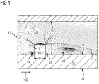
- Figure 1 shows a cooling channel 21 bordered by two opposing surfaces 13, 14, wherein from one of these surfaces 13 a rib 15 extends.
- the mean flow of said cooling fluid 17 around such a rib 15 is also shown.
- Characteristic for the flow field are the presence of four main vortical structures. On large vortical structure V1 is a large recirculation zone behind the rib 15, a smaller vortical structure V2 is between the rib downstream bottom corner and the large recirculation zone, one recirculation zone V4 in front of the rib 15 and one recirculation zone V3 on top 18 of the rib 15.
- Such a rib 15 is used as "turbulator" to enhance the turbulent intensity of the flow that promotes the heat transfer inside the cooling channel 21.
- the largest turbulence production occurs along a shear layer S1 where the shear stresses are very high.
- the functioning of the shear layer S1 depends on the rib height H as it impacts the size of the recirculation zone V1, where the flow has a low velocity, which increases the shear stress in contact with the high velocity of the mean flow.
- the vortical structure V3 on the rib top 18 increases the blockage of the rib, however, does not increase the turbulence production as the flow on the rib top 18 reattaches right before 25 the top downward corner 26 of the rib 15.
- the object of the present invention is to provide a coolable wall element with improved cooling properties, especially with fewer blockages inside of the cooling channel.
- the invention is based on the knowledge that on the top of the turbulence enhancing element as swirl appears that further blocks the remaining cross section in which the cooling fluid flows.
- the turbulence enhancing element comprises at its top surface a depression, preferably in the size, which is appropriate to house the top swirl between the remaining corners (upward and downward) of the turbulence enhancing element while increasing the not disturbed cross section of the cooling air flow.
- a coolable wall element for a hot gas environment comprising a first surface subjectable to hot gas and a second surface subjectable to a cooling fluid, the first and second surfaces are arranged opposite to each other, wherein the second surface comprises at least one turbulence enhancing element, but preferred multiple turbulence enhancing elements, each of which projects steplike from the second surface to a free ending top of the turbulence enhancing element, the respective tops each comprises a top surface having a depression.
- the depression has in cross section a triangular shape or a concave shape.
- a triangular shape is ease to manufacture while a concave shape of the depression is better equipped to house the top swirl.
- the top surface is free of a flat section being parallel to a second surface. This give the opportunity to house the swirl at least significantly between the first and second corners of the turbulence enhancing element.
- the triangular shape is symmetrical.
- wall element could be part of a turbine blade, a turbine vane, a ring segment, a combustor wall element or the like.
- the invention relates to a coolable wall element for gas turbines for a hot gas environment, comprising a first surface subjectable to hot gas and a second surface subjectable to a cooling fluid, the first and second surface are arranged opposite to each other, where in the second surface comprises at least one turbulence enhancing element which projects steplike from the second surface to a free ending top of the turbulence enhancing element, the top comprises a surface.
- the top surface comprises a depression.
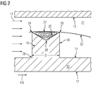
- Fig. 2 shows a not limiting first example of a coolable wall element 10.
- the wall element 10 could be part of a turbine vane, a turbine blade, a ring segment of the gas turbine or of a combustor wall, etc.
- the coolable wall element comprises a first surface 12 which is subjectable directly or, when covered by a single or multiple layer coating, indirectly to a hot environment.
- a hot gas HG streams parallel to first surface 12.
- the second surface 14 which is arranged opposite of the first surface 12 of the wall, at least one, preferred multiple turbulence enhancing elements 16 are distributed in a regular or irregular pattern.
- a cooling fluid 17, usually cooling air flows along the second surface 14, tripping at the location of the turbulence enhancing element 16.
- the displayed turbulence enhancing element 16 could be designed in rib form as trip strip having a longitudinal extension larger than 5 times of the distance D between the front surface 28 and the back surface 30. Usually the height H of the ribs 16 is similar to said distance D. Also, the turbulence enhancing element could have a pin shape (not shown). Then they are known as pedestals.
- the turbulence enhancing element 16 projects out of the plane of the surface 14 in a stepwise manner, i.e. with an angle of 90°. Other angle values are possible, as long as the turbulence enhancing element urges the cooling fluid 17 to trip over them.
- the turbulence enhancing element 16 ends at their free ending top 18. In other words, the turbulence enhancing elements do not merge into a third surface 13, which third surface 13 is arranged opposite of the second surface 14 for establishing there between a cooling channel 21 which cross section is locally restricted at the position of the turbulence enhancing element 16.
- the top 18 comprises a top surface 20. Contrary to the prior art, the top surface 20 is not flat, but comprises a depression 22. The depression 22 is located between an upward located corner 24 of the top 18 and a downward located corner 26 of the top 18
- the depression 22 has a corner 29, which in combination with the first and second corners 24, 26 define a virtual triangle shape.
- the depression 22 is as long as the turbulence enhancing element 16 as seen in a direction traverse to the global cooling fluid direction. In other words: the depression 22 extends along the complete longitudinal extension (not shown) of the turbulence enhancing element 16.
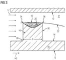
- the top surface 20 is concavely shaped between the upward and downward corners 24, 26 for creating said depression 22.
- the shape is of parabolic form, preferred broader than deep.
- the blockage ratio of the turbulence enhancing element 16 remains the same as the rib described in the prior art, thus creating the same magnitude of shear stresses.
- a front surface 28 and back surface 30 of the turbulence enhancing element remains straight to keep a larger wetted surface area and as the downstream recirculation zone is needed to create a large magnitude of shear flow.
- the inventive step lies in the shape of the top surface of the turbulence enhancing element, which is shaped as a groove either with corners or with a parabolic profile.
- the advantages of the proposed configuration are a reduction of the top recirculation zone and thus a reduction of the pressure drop by decreasing the blocked cooling fluid flow and an increase of the wetted surface area in comparison with a straight top surface.
Landscapes
- Engineering & Computer Science (AREA)
- Mechanical Engineering (AREA)
- General Engineering & Computer Science (AREA)
- Chemical & Material Sciences (AREA)
- Combustion & Propulsion (AREA)
- Turbine Rotor Nozzle Sealing (AREA)
Priority Applications (1)
| Application Number | Priority Date | Filing Date | Title |
|---|---|---|---|
| EP16180939.7A EP3276128A1 (de) | 2016-07-25 | 2016-07-25 | Kühlbares wandelement |
Applications Claiming Priority (1)
| Application Number | Priority Date | Filing Date | Title |
|---|---|---|---|
| EP16180939.7A EP3276128A1 (de) | 2016-07-25 | 2016-07-25 | Kühlbares wandelement |
Publications (1)
| Publication Number | Publication Date |
|---|---|
| EP3276128A1 true EP3276128A1 (de) | 2018-01-31 |
Family
ID=56567408
Family Applications (1)
| Application Number | Title | Priority Date | Filing Date |
|---|---|---|---|
| EP16180939.7A Withdrawn EP3276128A1 (de) | 2016-07-25 | 2016-07-25 | Kühlbares wandelement |
Country Status (1)
| Country | Link |
|---|---|
| EP (1) | EP3276128A1 (de) |
Cited By (2)
| Publication number | Priority date | Publication date | Assignee | Title |
|---|---|---|---|---|
| CN112282861A (zh) * | 2020-11-20 | 2021-01-29 | 西安热工研究院有限公司 | 一种透平叶片内部扰流装置 |
| CN112282862A (zh) * | 2020-11-20 | 2021-01-29 | 西安热工研究院有限公司 | 一种透平叶片锯齿状扰流装置 |
Citations (6)
| Publication number | Priority date | Publication date | Assignee | Title |
|---|---|---|---|---|
| US5538394A (en) * | 1993-12-28 | 1996-07-23 | Kabushiki Kaisha Toshiba | Cooled turbine blade for a gas turbine |
| US5695321A (en) * | 1991-12-17 | 1997-12-09 | General Electric Company | Turbine blade having variable configuration turbulators |
| EP1114976A2 (de) * | 1999-12-28 | 2001-07-11 | ALSTOM POWER (Schweiz) AG | Vorrichtung zur Kühlung einer, einen Strömungskanal umgebenden Strömungskanalwand mit wenigstens einem Rippenelement |
| US20110033312A1 (en) * | 2009-08-06 | 2011-02-10 | Ching-Pang Lee | Compound cooling flow turbulator for turbine component |
| EP2518429A1 (de) * | 2011-04-28 | 2012-10-31 | Siemens Aktiengesellschaft | Verbesserte Kühlfläche |
| WO2015050592A2 (en) * | 2013-06-14 | 2015-04-09 | United Technologies Corporation | Gas turbine engine combustor liner panel |
-
2016
- 2016-07-25 EP EP16180939.7A patent/EP3276128A1/de not_active Withdrawn
Patent Citations (6)
| Publication number | Priority date | Publication date | Assignee | Title |
|---|---|---|---|---|
| US5695321A (en) * | 1991-12-17 | 1997-12-09 | General Electric Company | Turbine blade having variable configuration turbulators |
| US5538394A (en) * | 1993-12-28 | 1996-07-23 | Kabushiki Kaisha Toshiba | Cooled turbine blade for a gas turbine |
| EP1114976A2 (de) * | 1999-12-28 | 2001-07-11 | ALSTOM POWER (Schweiz) AG | Vorrichtung zur Kühlung einer, einen Strömungskanal umgebenden Strömungskanalwand mit wenigstens einem Rippenelement |
| US20110033312A1 (en) * | 2009-08-06 | 2011-02-10 | Ching-Pang Lee | Compound cooling flow turbulator for turbine component |
| EP2518429A1 (de) * | 2011-04-28 | 2012-10-31 | Siemens Aktiengesellschaft | Verbesserte Kühlfläche |
| WO2015050592A2 (en) * | 2013-06-14 | 2015-04-09 | United Technologies Corporation | Gas turbine engine combustor liner panel |
Cited By (2)
| Publication number | Priority date | Publication date | Assignee | Title |
|---|---|---|---|---|
| CN112282861A (zh) * | 2020-11-20 | 2021-01-29 | 西安热工研究院有限公司 | 一种透平叶片内部扰流装置 |
| CN112282862A (zh) * | 2020-11-20 | 2021-01-29 | 西安热工研究院有限公司 | 一种透平叶片锯齿状扰流装置 |
Similar Documents
| Publication | Publication Date | Title |
|---|---|---|
| EP1873354B1 (de) | Vorderkantenkühlung über Chevron-Streifen | |
| US10196901B2 (en) | Cooling of engine components | |
| US8137056B2 (en) | Impingement cooled structure | |
| US8876475B1 (en) | Turbine blade with radial cooling passage having continuous discrete turbulence air mixers | |
| US20210041188A1 (en) | Turning vanes and heat exchangers and methods of making the same | |
| US7637720B1 (en) | Turbulator for a turbine airfoil cooling passage | |
| US6997675B2 (en) | Turbulated hole configurations for turbine blades | |
| EP2785979B1 (de) | Gekühlte turbinenleitschaufel oder gekühltes turbinenleitblatt für eine turbomaschine | |
| JP5189406B2 (ja) | ガスタービン翼およびこれを備えたガスタービン | |
| Sun et al. | Effect of bleed hole on internal flow and heat transfer in matrix cooling channel | |
| EP3276128A1 (de) | Kühlbares wandelement | |
| US7114916B2 (en) | Tailored turbulation for turbine blades | |
| KR101422187B1 (ko) | 냉각장치 내부냉각유로의 내면에 부착되는 핀-휜의 새로운 형상 구조 | |
| CN107191230B (zh) | 一种叶片冷却微通道结构 | |
| KR20170052768A (ko) | 핀-휜 및 이를 포함하는 냉각장치 | |
| KR101368331B1 (ko) | 일부 측면이 비대칭인 냉각유로용 리브, 이를 구비한 냉각장치 및 가스터빈 블레이드 | |
| US9551229B2 (en) | Turbine airfoil with an internal cooling system having trip strips with reduced pressure drop | |
| JP6108982B2 (ja) | タービン翼及びこれを備える回転機械 | |
| US8506241B1 (en) | Turbine blade with cooling and tip sealing | |
| US8602735B1 (en) | Turbine blade with diffuser cooling channel | |
| JP5496263B2 (ja) | ガスタービン翼およびこれを備えたガスタービン | |
| WO2015156816A1 (en) | Turbine airfoil with an internal cooling system having turbulators with anti-vortex ribs | |
| RU2626285C1 (ru) | Лопаточная решетка турбомашины | |
| Ekkad | Internal Cooling | |
| KR101919328B1 (ko) | 가스터빈 블레이드 내부 격자 냉각 방식의 냉각 성능 향상을 위한 c-가이드 구조 |
Legal Events
| Date | Code | Title | Description |
|---|---|---|---|
| PUAI | Public reference made under article 153(3) epc to a published international application that has entered the european phase |
Free format text: ORIGINAL CODE: 0009012 |
|
| AK | Designated contracting states |
Kind code of ref document: A1 Designated state(s): AL AT BE BG CH CY CZ DE DK EE ES FI FR GB GR HR HU IE IS IT LI LT LU LV MC MK MT NL NO PL PT RO RS SE SI SK SM TR |
|
| AX | Request for extension of the european patent |
Extension state: BA ME |
|
| STAA | Information on the status of an ep patent application or granted ep patent |
Free format text: STATUS: THE APPLICATION IS DEEMED TO BE WITHDRAWN |
|
| 18D | Application deemed to be withdrawn |
Effective date: 20180801 |