EP3276128A1 - Coolable wall element - Google Patents
Coolable wall element Download PDFInfo
- Publication number
- EP3276128A1 EP3276128A1 EP16180939.7A EP16180939A EP3276128A1 EP 3276128 A1 EP3276128 A1 EP 3276128A1 EP 16180939 A EP16180939 A EP 16180939A EP 3276128 A1 EP3276128 A1 EP 3276128A1
- Authority
- EP
- European Patent Office
- Prior art keywords
- wall element
- turbulence enhancing
- depression
- cooling
- enhancing element
- Prior art date
- Legal status (The legal status is an assumption and is not a legal conclusion. Google has not performed a legal analysis and makes no representation as to the accuracy of the status listed.)
- Withdrawn
Links
Images
Classifications
-
- F—MECHANICAL ENGINEERING; LIGHTING; HEATING; WEAPONS; BLASTING
- F01—MACHINES OR ENGINES IN GENERAL; ENGINE PLANTS IN GENERAL; STEAM ENGINES
- F01D—NON-POSITIVE DISPLACEMENT MACHINES OR ENGINES, e.g. STEAM TURBINES
- F01D5/00—Blades; Blade-carrying members; Heating, heat-insulating, cooling or antivibration means on the blades or the members
- F01D5/12—Blades
- F01D5/14—Form or construction
- F01D5/18—Hollow blades, i.e. blades with cooling or heating channels or cavities; Heating, heat-insulating or cooling means on blades
- F01D5/187—Convection cooling
-
- F—MECHANICAL ENGINEERING; LIGHTING; HEATING; WEAPONS; BLASTING
- F01—MACHINES OR ENGINES IN GENERAL; ENGINE PLANTS IN GENERAL; STEAM ENGINES
- F01D—NON-POSITIVE DISPLACEMENT MACHINES OR ENGINES, e.g. STEAM TURBINES
- F01D25/00—Component parts, details, or accessories, not provided for in, or of interest apart from, other groups
- F01D25/08—Cooling; Heating; Heat-insulation
- F01D25/12—Cooling
-
- F—MECHANICAL ENGINEERING; LIGHTING; HEATING; WEAPONS; BLASTING
- F23—COMBUSTION APPARATUS; COMBUSTION PROCESSES
- F23R—GENERATING COMBUSTION PRODUCTS OF HIGH PRESSURE OR HIGH VELOCITY, e.g. GAS-TURBINE COMBUSTION CHAMBERS
- F23R3/00—Continuous combustion chambers using liquid or gaseous fuel
- F23R3/002—Wall structures
-
- F—MECHANICAL ENGINEERING; LIGHTING; HEATING; WEAPONS; BLASTING
- F23—COMBUSTION APPARATUS; COMBUSTION PROCESSES
- F23R—GENERATING COMBUSTION PRODUCTS OF HIGH PRESSURE OR HIGH VELOCITY, e.g. GAS-TURBINE COMBUSTION CHAMBERS
- F23R3/00—Continuous combustion chambers using liquid or gaseous fuel
- F23R3/005—Combined with pressure or heat exchangers
-
- F—MECHANICAL ENGINEERING; LIGHTING; HEATING; WEAPONS; BLASTING
- F05—INDEXING SCHEMES RELATING TO ENGINES OR PUMPS IN VARIOUS SUBCLASSES OF CLASSES F01-F04
- F05D—INDEXING SCHEME FOR ASPECTS RELATING TO NON-POSITIVE-DISPLACEMENT MACHINES OR ENGINES, GAS-TURBINES OR JET-PROPULSION PLANTS
- F05D2250/00—Geometry
- F05D2250/10—Two-dimensional
- F05D2250/11—Two-dimensional triangular
-
- F—MECHANICAL ENGINEERING; LIGHTING; HEATING; WEAPONS; BLASTING
- F05—INDEXING SCHEMES RELATING TO ENGINES OR PUMPS IN VARIOUS SUBCLASSES OF CLASSES F01-F04
- F05D—INDEXING SCHEME FOR ASPECTS RELATING TO NON-POSITIVE-DISPLACEMENT MACHINES OR ENGINES, GAS-TURBINES OR JET-PROPULSION PLANTS
- F05D2250/00—Geometry
- F05D2250/10—Two-dimensional
- F05D2250/16—Two-dimensional parabolic
-
- F—MECHANICAL ENGINEERING; LIGHTING; HEATING; WEAPONS; BLASTING
- F05—INDEXING SCHEMES RELATING TO ENGINES OR PUMPS IN VARIOUS SUBCLASSES OF CLASSES F01-F04
- F05D—INDEXING SCHEME FOR ASPECTS RELATING TO NON-POSITIVE-DISPLACEMENT MACHINES OR ENGINES, GAS-TURBINES OR JET-PROPULSION PLANTS
- F05D2250/00—Geometry
- F05D2250/20—Three-dimensional
- F05D2250/29—Three-dimensional machined; miscellaneous
- F05D2250/294—Three-dimensional machined; miscellaneous grooved
-
- F—MECHANICAL ENGINEERING; LIGHTING; HEATING; WEAPONS; BLASTING
- F05—INDEXING SCHEMES RELATING TO ENGINES OR PUMPS IN VARIOUS SUBCLASSES OF CLASSES F01-F04
- F05D—INDEXING SCHEME FOR ASPECTS RELATING TO NON-POSITIVE-DISPLACEMENT MACHINES OR ENGINES, GAS-TURBINES OR JET-PROPULSION PLANTS
- F05D2260/00—Function
- F05D2260/20—Heat transfer, e.g. cooling
- F05D2260/221—Improvement of heat transfer
- F05D2260/2214—Improvement of heat transfer by increasing the heat transfer surface
- F05D2260/22141—Improvement of heat transfer by increasing the heat transfer surface using fins or ribs
-
- F—MECHANICAL ENGINEERING; LIGHTING; HEATING; WEAPONS; BLASTING
- F23—COMBUSTION APPARATUS; COMBUSTION PROCESSES
- F23R—GENERATING COMBUSTION PRODUCTS OF HIGH PRESSURE OR HIGH VELOCITY, e.g. GAS-TURBINE COMBUSTION CHAMBERS
- F23R2900/00—Special features of, or arrangements for continuous combustion chambers; Combustion processes therefor
- F23R2900/03043—Convection cooled combustion chamber walls with means for guiding the cooling air flow
Definitions
- the invention relates to a coolable wall element for gas turbines, i.e. embodied as turbine blade or turbine vane, etc.
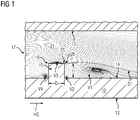
- Figure 1 shows a cooling channel 21 bordered by two opposing surfaces 13, 14, wherein from one of these surfaces 13 a rib 15 extends.
- the mean flow of said cooling fluid 17 around such a rib 15 is also shown.
- Characteristic for the flow field are the presence of four main vortical structures. On large vortical structure V1 is a large recirculation zone behind the rib 15, a smaller vortical structure V2 is between the rib downstream bottom corner and the large recirculation zone, one recirculation zone V4 in front of the rib 15 and one recirculation zone V3 on top 18 of the rib 15.
- Such a rib 15 is used as "turbulator" to enhance the turbulent intensity of the flow that promotes the heat transfer inside the cooling channel 21.
- the largest turbulence production occurs along a shear layer S1 where the shear stresses are very high.
- the functioning of the shear layer S1 depends on the rib height H as it impacts the size of the recirculation zone V1, where the flow has a low velocity, which increases the shear stress in contact with the high velocity of the mean flow.
- the vortical structure V3 on the rib top 18 increases the blockage of the rib, however, does not increase the turbulence production as the flow on the rib top 18 reattaches right before 25 the top downward corner 26 of the rib 15.
- the object of the present invention is to provide a coolable wall element with improved cooling properties, especially with fewer blockages inside of the cooling channel.
- the invention is based on the knowledge that on the top of the turbulence enhancing element as swirl appears that further blocks the remaining cross section in which the cooling fluid flows.
- the turbulence enhancing element comprises at its top surface a depression, preferably in the size, which is appropriate to house the top swirl between the remaining corners (upward and downward) of the turbulence enhancing element while increasing the not disturbed cross section of the cooling air flow.
- a coolable wall element for a hot gas environment comprising a first surface subjectable to hot gas and a second surface subjectable to a cooling fluid, the first and second surfaces are arranged opposite to each other, wherein the second surface comprises at least one turbulence enhancing element, but preferred multiple turbulence enhancing elements, each of which projects steplike from the second surface to a free ending top of the turbulence enhancing element, the respective tops each comprises a top surface having a depression.
- the depression has in cross section a triangular shape or a concave shape.
- a triangular shape is ease to manufacture while a concave shape of the depression is better equipped to house the top swirl.
- the top surface is free of a flat section being parallel to a second surface. This give the opportunity to house the swirl at least significantly between the first and second corners of the turbulence enhancing element.
- the triangular shape is symmetrical.
- wall element could be part of a turbine blade, a turbine vane, a ring segment, a combustor wall element or the like.
- the invention relates to a coolable wall element for gas turbines for a hot gas environment, comprising a first surface subjectable to hot gas and a second surface subjectable to a cooling fluid, the first and second surface are arranged opposite to each other, where in the second surface comprises at least one turbulence enhancing element which projects steplike from the second surface to a free ending top of the turbulence enhancing element, the top comprises a surface.
- the top surface comprises a depression.
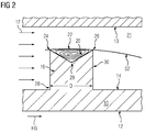
- Fig. 2 shows a not limiting first example of a coolable wall element 10.
- the wall element 10 could be part of a turbine vane, a turbine blade, a ring segment of the gas turbine or of a combustor wall, etc.
- the coolable wall element comprises a first surface 12 which is subjectable directly or, when covered by a single or multiple layer coating, indirectly to a hot environment.
- a hot gas HG streams parallel to first surface 12.
- the second surface 14 which is arranged opposite of the first surface 12 of the wall, at least one, preferred multiple turbulence enhancing elements 16 are distributed in a regular or irregular pattern.
- a cooling fluid 17, usually cooling air flows along the second surface 14, tripping at the location of the turbulence enhancing element 16.
- the displayed turbulence enhancing element 16 could be designed in rib form as trip strip having a longitudinal extension larger than 5 times of the distance D between the front surface 28 and the back surface 30. Usually the height H of the ribs 16 is similar to said distance D. Also, the turbulence enhancing element could have a pin shape (not shown). Then they are known as pedestals.
- the turbulence enhancing element 16 projects out of the plane of the surface 14 in a stepwise manner, i.e. with an angle of 90°. Other angle values are possible, as long as the turbulence enhancing element urges the cooling fluid 17 to trip over them.
- the turbulence enhancing element 16 ends at their free ending top 18. In other words, the turbulence enhancing elements do not merge into a third surface 13, which third surface 13 is arranged opposite of the second surface 14 for establishing there between a cooling channel 21 which cross section is locally restricted at the position of the turbulence enhancing element 16.
- the top 18 comprises a top surface 20. Contrary to the prior art, the top surface 20 is not flat, but comprises a depression 22. The depression 22 is located between an upward located corner 24 of the top 18 and a downward located corner 26 of the top 18
- the depression 22 has a corner 29, which in combination with the first and second corners 24, 26 define a virtual triangle shape.
- the depression 22 is as long as the turbulence enhancing element 16 as seen in a direction traverse to the global cooling fluid direction. In other words: the depression 22 extends along the complete longitudinal extension (not shown) of the turbulence enhancing element 16.
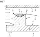
- the top surface 20 is concavely shaped between the upward and downward corners 24, 26 for creating said depression 22.
- the shape is of parabolic form, preferred broader than deep.
- the blockage ratio of the turbulence enhancing element 16 remains the same as the rib described in the prior art, thus creating the same magnitude of shear stresses.
- a front surface 28 and back surface 30 of the turbulence enhancing element remains straight to keep a larger wetted surface area and as the downstream recirculation zone is needed to create a large magnitude of shear flow.
- the inventive step lies in the shape of the top surface of the turbulence enhancing element, which is shaped as a groove either with corners or with a parabolic profile.
- the advantages of the proposed configuration are a reduction of the top recirculation zone and thus a reduction of the pressure drop by decreasing the blocked cooling fluid flow and an increase of the wetted surface area in comparison with a straight top surface.
Landscapes
- Engineering & Computer Science (AREA)
- Mechanical Engineering (AREA)
- General Engineering & Computer Science (AREA)
- Chemical & Material Sciences (AREA)
- Combustion & Propulsion (AREA)
- Turbine Rotor Nozzle Sealing (AREA)
Abstract
The invention relates to a coolable wall element (10) for gas turbines for a hot gas environment, comprising a first surface (12) subjectable to a hot gas and a second surface (14) subjectable to a cooling fluid (17), the first and second surface (12, 14) are arranged opposite to each other, where in the second surface (14) comprises at least one turbulence enhancing element (16) which projects steplike from the second surface (14) to a free ending top (18) of the turbulence enhancing element (16), the top (18) comprises a top surface (20). To provide a coolable wall element (10) with enhanced cooling properties and fewer blockages inside of a cooling cannel, it is proposed that the top surface (20) comprises a depression (22).
Description
- The invention relates to a coolable wall element for gas turbines, i.e. embodied as turbine blade or turbine vane, etc.
- State-of-the-art internal cooling techniques for temperature loaded blades and vanes use roughened serpentine passages, in which the coolant passes through. Roughness elements, such as pin fins, dimples and most often ribs are usually used to meet the cooling requirements. However, one major problem of the required cooling is the needed coolant flow and the associated pressure drop of the coolant inside the cooling passages, which penalizes the overall efficiency of the gas turbine cycle. Major losses are created by the friction of the used cooling fluid and the blockage of the used turbulators. To date rib-roughened elements have the largest potential among the roughness elements.
-
Figure 1 shows acooling channel 21 bordered by twoopposing surfaces rib 15 extends. The mean flow of saidcooling fluid 17 around such arib 15 is also shown. Characteristic for the flow field are the presence of four main vortical structures. On large vortical structure V1 is a large recirculation zone behind therib 15, a smaller vortical structure V2 is between the rib downstream bottom corner and the large recirculation zone, one recirculation zone V4 in front of therib 15 and one recirculation zone V3 ontop 18 of therib 15. Such arib 15 is used as "turbulator" to enhance the turbulent intensity of the flow that promotes the heat transfer inside thecooling channel 21. The largest turbulence production occurs along a shear layer S1 where the shear stresses are very high. The functioning of the shear layer S1 depends on the rib height H as it impacts the size of the recirculation zone V1, where the flow has a low velocity, which increases the shear stress in contact with the high velocity of the mean flow. The vortical structure V3 on therib top 18 increases the blockage of the rib, however, does not increase the turbulence production as the flow on therib top 18 reattaches right before 25 the topdownward corner 26 of therib 15. - Hence, the object of the present invention is to provide a coolable wall element with improved cooling properties, especially with fewer blockages inside of the cooling channel.
- The problem of the invention is solved with a coolable wall element according to the features mentioned in claim 1. Further preferred embodiments are described in the depending claims.
- The invention is based on the knowledge that on the top of the turbulence enhancing element as swirl appears that further blocks the remaining cross section in which the cooling fluid flows. To eliminate this effect of further reduced cross section the turbulence enhancing element comprises at its top surface a depression, preferably in the size, which is appropriate to house the top swirl between the remaining corners (upward and downward) of the turbulence enhancing element while increasing the not disturbed cross section of the cooling air flow.
- For this reason, a coolable wall element for a hot gas environment comprising a first surface subjectable to hot gas and a second surface subjectable to a cooling fluid, the first and second surfaces are arranged opposite to each other, wherein the second surface comprises at least one turbulence enhancing element, but preferred multiple turbulence enhancing elements, each of which projects steplike from the second surface to a free ending top of the turbulence enhancing element, the respective tops each comprises a top surface having a depression.
- Besides the allocation of a space for housing the top swirl the overall area of the surface of the turbulence enhancing element is increased leading to an enhanced heat transfer.
- Preferable the depression has in cross section a triangular shape or a concave shape. A triangular shape is ease to manufacture while a concave shape of the depression is better equipped to house the top swirl.
- In a further preferred embodiment the top surface is free of a flat section being parallel to a second surface. This give the opportunity to house the swirl at least significantly between the first and second corners of the turbulence enhancing element.
- In a further preferred embodiment the triangular shape is symmetrical. Of course the before mention wall element could be part of a turbine blade, a turbine vane, a ring segment, a combustor wall element or the like.
- In summary the invention relates to a coolable wall element for gas turbines for a hot gas environment, comprising a first surface subjectable to hot gas and a second surface subjectable to a cooling fluid, the first and second surface are arranged opposite to each other, where in the second surface comprises at least one turbulence enhancing element which projects steplike from the second surface to a free ending top of the turbulence enhancing element, the top comprises a surface. To provide a coolable wall element with enhanced cooling properties and fewer blockages inside of a cooling cannel, it is proposed that the top surface comprises a depression.
- The invention displayed in the accompanied drawing will be explained in the following description without limiting the scope of the invention. In the drawing and detailed description identical features are numbered with the same identifiers.
- It shows:
- Fig. 1
- a cross section through a coolable wall element according to the prior art,
- Fig. 2
- a cross section through a coolable wall element according to a first preferred embodiment and
- Fig. 3
- a cross section through a coolable wall element according to a second preferred embodiment.
-
Fig. 2 shows a not limiting first example of acoolable wall element 10. Thewall element 10 could be part of a turbine vane, a turbine blade, a ring segment of the gas turbine or of a combustor wall, etc. - The coolable wall element comprises a
first surface 12 which is subjectable directly or, when covered by a single or multiple layer coating, indirectly to a hot environment. Usually a hot gas HG streams parallel tofirst surface 12. To achieve a required lifetime of thewall element 10 it has to be cooled down to appropriate wall temperatures. Therefore on thesecond surface 14, which is arranged opposite of thefirst surface 12 of the wall, at least one, preferred multipleturbulence enhancing elements 16 are distributed in a regular or irregular pattern. During operation acooling fluid 17, usually cooling air, flows along thesecond surface 14, tripping at the location of theturbulence enhancing element 16. - The displayed
turbulence enhancing element 16 could be designed in rib form as trip strip having a longitudinal extension larger than 5 times of the distance D between thefront surface 28 and theback surface 30. Usually the height H of theribs 16 is similar to said distance D. Also, the turbulence enhancing element could have a pin shape (not shown). Then they are known as pedestals. - The
turbulence enhancing element 16 projects out of the plane of thesurface 14 in a stepwise manner, i.e. with an angle of 90°. Other angle values are possible, as long as the turbulence enhancing element urges thecooling fluid 17 to trip over them. - The
turbulence enhancing element 16 ends at their free endingtop 18. In other words, the turbulence enhancing elements do not merge into athird surface 13, whichthird surface 13 is arranged opposite of thesecond surface 14 for establishing there between acooling channel 21 which cross section is locally restricted at the position of theturbulence enhancing element 16. - The
top 18 comprises atop surface 20. Contrary to the prior art, thetop surface 20 is not flat, but comprises adepression 22. Thedepression 22 is located between an upward locatedcorner 24 of thetop 18 and a downward locatedcorner 26 of the top 18 - According to a first example of the invention, displayed in
Fig. 2 , thedepression 22 has acorner 29, which in combination with the first andsecond corners depression 22 is as long as theturbulence enhancing element 16 as seen in a direction traverse to the global cooling fluid direction. In other words: thedepression 22 extends along the complete longitudinal extension (not shown) of theturbulence enhancing element 16. - According to a second example of the invention, displayed in
Fig. 3 , thetop surface 20 is concavely shaped between the upward anddownward corners depression 22. Preferred, the shape is of parabolic form, preferred broader than deep. - The blockage ratio of the
turbulence enhancing element 16 remains the same as the rib described in the prior art, thus creating the same magnitude of shear stresses. Afront surface 28 andback surface 30 of the turbulence enhancing element remains straight to keep a larger wetted surface area and as the downstream recirculation zone is needed to create a large magnitude of shear flow. - The inventive step lies in the shape of the top surface of the turbulence enhancing element, which is shaped as a groove either with corners or with a parabolic profile.
The advantages of the proposed configuration are a reduction of the top recirculation zone and thus a reduction of the pressure drop by decreasing the blocked cooling fluid flow and an increase of the wetted surface area in comparison with a straight top surface.
Claims (5)
- A coolable wall element (10) for a hot environment comprising a first surface subjectable (12) to a hot gas and an second surface (14) subjectable to a cooling fluid (17), the first and second surfaces (12, 14) are arranged opposite to each other,
wherein the second surface (14) comprises at least one turbulence enhancing element (16), which projects steplike from the second surface (14) to a free ending top (18) of the turbulence enhancing element (16), the top (18) comprises a top surface (20),
characterized in that the top surface (20) comprises a depression. - Wall element (10) according to claim 1,
wherein the depression (22) has in cross section a triangular or a concave shape. - Wall element (10) according to claim 1 or 2,
wherein the top surface (20) is free of a flat section being parallel to the second surface (14). - Wall element (10) according to claim 2 or 3,
wherein the triangular shape is symmetrical. - Wall element (10) according to one of the claims 1 to 4, embodied as a turbine blade, turbine vane, a ring segment or combustor wall element.
Priority Applications (1)
| Application Number | Priority Date | Filing Date | Title |
|---|---|---|---|
| EP16180939.7A EP3276128A1 (en) | 2016-07-25 | 2016-07-25 | Coolable wall element |
Applications Claiming Priority (1)
| Application Number | Priority Date | Filing Date | Title |
|---|---|---|---|
| EP16180939.7A EP3276128A1 (en) | 2016-07-25 | 2016-07-25 | Coolable wall element |
Publications (1)
| Publication Number | Publication Date |
|---|---|
| EP3276128A1 true EP3276128A1 (en) | 2018-01-31 |
Family
ID=56567408
Family Applications (1)
| Application Number | Title | Priority Date | Filing Date |
|---|---|---|---|
| EP16180939.7A Withdrawn EP3276128A1 (en) | 2016-07-25 | 2016-07-25 | Coolable wall element |
Country Status (1)
| Country | Link |
|---|---|
| EP (1) | EP3276128A1 (en) |
Cited By (2)
| Publication number | Priority date | Publication date | Assignee | Title |
|---|---|---|---|---|
| CN112282861A (en) * | 2020-11-20 | 2021-01-29 | 西安热工研究院有限公司 | An internal turbulence device for a turbine blade |
| CN112282862A (en) * | 2020-11-20 | 2021-01-29 | 西安热工研究院有限公司 | Turbine blade sawtooth turbulence device |
Citations (6)
| Publication number | Priority date | Publication date | Assignee | Title |
|---|---|---|---|---|
| US5538394A (en) * | 1993-12-28 | 1996-07-23 | Kabushiki Kaisha Toshiba | Cooled turbine blade for a gas turbine |
| US5695321A (en) * | 1991-12-17 | 1997-12-09 | General Electric Company | Turbine blade having variable configuration turbulators |
| EP1114976A2 (en) * | 1999-12-28 | 2001-07-11 | ALSTOM POWER (Schweiz) AG | Device for cooling a conduit wall provided with at least one fin element |
| US20110033312A1 (en) * | 2009-08-06 | 2011-02-10 | Ching-Pang Lee | Compound cooling flow turbulator for turbine component |
| EP2518429A1 (en) * | 2011-04-28 | 2012-10-31 | Siemens Aktiengesellschaft | An enhanced cooling surface |
| WO2015050592A2 (en) * | 2013-06-14 | 2015-04-09 | United Technologies Corporation | Gas turbine engine combustor liner panel |
-
2016
- 2016-07-25 EP EP16180939.7A patent/EP3276128A1/en not_active Withdrawn
Patent Citations (6)
| Publication number | Priority date | Publication date | Assignee | Title |
|---|---|---|---|---|
| US5695321A (en) * | 1991-12-17 | 1997-12-09 | General Electric Company | Turbine blade having variable configuration turbulators |
| US5538394A (en) * | 1993-12-28 | 1996-07-23 | Kabushiki Kaisha Toshiba | Cooled turbine blade for a gas turbine |
| EP1114976A2 (en) * | 1999-12-28 | 2001-07-11 | ALSTOM POWER (Schweiz) AG | Device for cooling a conduit wall provided with at least one fin element |
| US20110033312A1 (en) * | 2009-08-06 | 2011-02-10 | Ching-Pang Lee | Compound cooling flow turbulator for turbine component |
| EP2518429A1 (en) * | 2011-04-28 | 2012-10-31 | Siemens Aktiengesellschaft | An enhanced cooling surface |
| WO2015050592A2 (en) * | 2013-06-14 | 2015-04-09 | United Technologies Corporation | Gas turbine engine combustor liner panel |
Cited By (2)
| Publication number | Priority date | Publication date | Assignee | Title |
|---|---|---|---|---|
| CN112282861A (en) * | 2020-11-20 | 2021-01-29 | 西安热工研究院有限公司 | An internal turbulence device for a turbine blade |
| CN112282862A (en) * | 2020-11-20 | 2021-01-29 | 西安热工研究院有限公司 | Turbine blade sawtooth turbulence device |
Similar Documents
| Publication | Publication Date | Title |
|---|---|---|
| EP1873354B1 (en) | Leading edge cooling using chevron trip strips | |
| US10196901B2 (en) | Cooling of engine components | |
| US8137056B2 (en) | Impingement cooled structure | |
| US8876475B1 (en) | Turbine blade with radial cooling passage having continuous discrete turbulence air mixers | |
| US7637720B1 (en) | Turbulator for a turbine airfoil cooling passage | |
| US20210041188A1 (en) | Turning vanes and heat exchangers and methods of making the same | |
| US6997675B2 (en) | Turbulated hole configurations for turbine blades | |
| US9896942B2 (en) | Cooled turbine guide vane or blade for a turbomachine | |
| JP2009275605A (en) | Gas turbine blade and gas turbine equipped with the same | |
| Sun et al. | Effect of bleed hole on internal flow and heat transfer in matrix cooling channel | |
| US8016563B1 (en) | Turbine blade with tip turn cooling | |
| EP3276128A1 (en) | Coolable wall element | |
| US7114916B2 (en) | Tailored turbulation for turbine blades | |
| KR101422187B1 (en) | The novel shape of pin-fin attached to inner surface of colling passage on the inside cooling apparatus | |
| CN107191230B (en) | A kind of blade cooling microchannel structure | |
| KR20170052768A (en) | Pin-fin and cooling apparatus having the same | |
| KR101368331B1 (en) | Asymmetric rib for cooling passage, gas turbine blade and cooling apparatus having the same | |
| US9551229B2 (en) | Turbine airfoil with an internal cooling system having trip strips with reduced pressure drop | |
| JP6108982B2 (en) | Turbine blade and rotating machine equipped with the same | |
| US8602735B1 (en) | Turbine blade with diffuser cooling channel | |
| JP5496263B2 (en) | Gas turbine blade and gas turbine provided with the same | |
| WO2015156816A1 (en) | Turbine airfoil with an internal cooling system having turbulators with anti-vortex ribs | |
| US20190078443A1 (en) | Film cooling hole in gas turbine components | |
| RU2626285C1 (en) | Turbomachine blade system | |
| Ekkad | Internal Cooling |
Legal Events
| Date | Code | Title | Description |
|---|---|---|---|
| PUAI | Public reference made under article 153(3) epc to a published international application that has entered the european phase |
Free format text: ORIGINAL CODE: 0009012 |
|
| AK | Designated contracting states |
Kind code of ref document: A1 Designated state(s): AL AT BE BG CH CY CZ DE DK EE ES FI FR GB GR HR HU IE IS IT LI LT LU LV MC MK MT NL NO PL PT RO RS SE SI SK SM TR |
|
| AX | Request for extension of the european patent |
Extension state: BA ME |
|
| STAA | Information on the status of an ep patent application or granted ep patent |
Free format text: STATUS: THE APPLICATION IS DEEMED TO BE WITHDRAWN |
|
| 18D | Application deemed to be withdrawn |
Effective date: 20180801 |