EP3276111A1 - Lock with a slide for covering lock core - Google Patents
Lock with a slide for covering lock core Download PDFInfo
- Publication number
- EP3276111A1 EP3276111A1 EP17159518.4A EP17159518A EP3276111A1 EP 3276111 A1 EP3276111 A1 EP 3276111A1 EP 17159518 A EP17159518 A EP 17159518A EP 3276111 A1 EP3276111 A1 EP 3276111A1
- Authority
- EP
- European Patent Office
- Prior art keywords
- slide
- spring
- lock
- insertion hole
- pivot
- Prior art date
- Legal status (The legal status is an assumption and is not a legal conclusion. Google has not performed a legal analysis and makes no representation as to the accuracy of the status listed.)
- Granted
Links
- 230000037431 insertion Effects 0.000 claims abstract description 37
- 238000003780 insertion Methods 0.000 claims abstract description 37
- 238000009434 installation Methods 0.000 claims abstract description 28
- 239000000428 dust Substances 0.000 abstract description 6
- XLYOFNOQVPJJNP-UHFFFAOYSA-N water Substances O XLYOFNOQVPJJNP-UHFFFAOYSA-N 0.000 abstract 1
- 239000011324 bead Substances 0.000 description 6
- 239000000314 lubricant Substances 0.000 description 2
- 230000002035 prolonged effect Effects 0.000 description 2
- 239000002184 metal Substances 0.000 description 1
Images


Classifications
-
- E—FIXED CONSTRUCTIONS
- E05—LOCKS; KEYS; WINDOW OR DOOR FITTINGS; SAFES
- E05B—LOCKS; ACCESSORIES THEREFOR; HANDCUFFS
- E05B67/00—Padlocks; Details thereof
- E05B67/02—Cases
-
- E—FIXED CONSTRUCTIONS
- E05—LOCKS; KEYS; WINDOW OR DOOR FITTINGS; SAFES
- E05B—LOCKS; ACCESSORIES THEREFOR; HANDCUFFS
- E05B17/00—Accessories in connection with locks
- E05B17/14—Closures or guards for keyholes
- E05B17/18—Closures or guards for keyholes shaped as lids or slides
- E05B17/185—Closures or guards for keyholes shaped as lids or slides pivoting about an axis perpendicular to the lock face
-
- E—FIXED CONSTRUCTIONS
- E05—LOCKS; KEYS; WINDOW OR DOOR FITTINGS; SAFES
- E05B—LOCKS; ACCESSORIES THEREFOR; HANDCUFFS
- E05B67/00—Padlocks; Details thereof
- E05B67/06—Shackles; Arrangement of the shackle
- E05B67/22—Padlocks with sliding shackles, with or without rotary or pivotal movement
- E05B67/24—Padlocks with sliding shackles, with or without rotary or pivotal movement with built- in cylinder locks
-
- E—FIXED CONSTRUCTIONS
- E05—LOCKS; KEYS; WINDOW OR DOOR FITTINGS; SAFES
- E05B—LOCKS; ACCESSORIES THEREFOR; HANDCUFFS
- E05B17/00—Accessories in connection with locks
- E05B17/14—Closures or guards for keyholes
- E05B17/18—Closures or guards for keyholes shaped as lids or slides
-
- Y—GENERAL TAGGING OF NEW TECHNOLOGICAL DEVELOPMENTS; GENERAL TAGGING OF CROSS-SECTIONAL TECHNOLOGIES SPANNING OVER SEVERAL SECTIONS OF THE IPC; TECHNICAL SUBJECTS COVERED BY FORMER USPC CROSS-REFERENCE ART COLLECTIONS [XRACs] AND DIGESTS
- Y10—TECHNICAL SUBJECTS COVERED BY FORMER USPC
- Y10T—TECHNICAL SUBJECTS COVERED BY FORMER US CLASSIFICATION
- Y10T70/00—Locks
- Y10T70/70—Operating mechanism
- Y10T70/7441—Key
- Y10T70/7915—Tampering prevention or attack defeating
- Y10T70/7955—Keyhole guards
-
- Y—GENERAL TAGGING OF NEW TECHNOLOGICAL DEVELOPMENTS; GENERAL TAGGING OF CROSS-SECTIONAL TECHNOLOGIES SPANNING OVER SEVERAL SECTIONS OF THE IPC; TECHNICAL SUBJECTS COVERED BY FORMER USPC CROSS-REFERENCE ART COLLECTIONS [XRACs] AND DIGESTS
- Y10—TECHNICAL SUBJECTS COVERED BY FORMER USPC
- Y10T—TECHNICAL SUBJECTS COVERED BY FORMER US CLASSIFICATION
- Y10T70/00—Locks
- Y10T70/80—Parts, attachments, accessories and adjuncts
- Y10T70/8432—For key-operated mechanism
- Y10T70/8649—Keyhole covers
Definitions
- the present invention relates to a lock, and more particularly, to a lock with a slide which is moved to a position to cover the lock core when the lock is not in use.
- the conventional locks generally comprise a housing with a core located therein.
- a bead system is received in the core and includes multiple recesses and each recess receives multiple beads therein.
- resilient members and duplicate bead units are added in the bead system.
- the core has a keyhole in which a key can be inserted to arrange the beads to a unlock position so that the core can be rotated.
- the key hole is exposed and dust, moisture can easily enter the core to cause rusting to the parts in the core because most of the parts are made by metal.
- the rusted parts may affect rotation of the core.
- pebbles and sands may also enter into the core, and some parts in the core has lubricant attached thereto and the pebbles, sands and dust are easily attached to the lubricant to block the movement of the beads such that the lock is difficult to be locked or unlocked.
- the present invention intends to provide a lock with a slide which covers the core when the lock is not in use so as to eliminate the shortcomings mentioned above.
- the present invention relates to a lock and comprises a housing having an installation recess and an insertion hole defined in the underside thereof.
- a flat face and a protrusion are formed on the underside of the housing, wherein the protrusion is higher than the flat face and has a first end face.
- a pivot is located in the insertion hole and has a first end and a second end, and a slide is connected to the second end of the pivot.
- a spring is located in the insertion hole and applies a first resilient force toward the insertion hole and a second resilient force toward a direction that the slide pivots. The first end of the spring is fixed in the insertion hole and the second end of the spring is connected to the pivot.
- the slide When the slide is located at a first position, the slide is applied by the first resilient force of the spring and located at the flat face so that the slide is applied by the second resilient force of the spring to cover the installation recess.
- the slide When the slide is located at a second position, the slide is pivoted to overcome the second resilient force of the spring and has at least one portion thereof not covering the installation recess.
- the slide When the slide is located at a third position, the slide is pivoted and the pivot moves axially to compress and spring and to overcome the first resilient force of the spring, such that the slide is located above the first end face of the protrusion and continuously pivoted, and at least one portion of the slide does not cover the installation recess.
- the slide contacts the first end face when the slide is positioned at the second position.
- the spring has a first leg on the first end thereof, and the insertion hole has a side hole defined in the inside thereof.
- the first leg is fixed in the side hole to fix the spring to the insertion hole.
- the spring has a second leg on the second end thereof, and the pivot has a slot defined in the first end thereof. The second leg is engaged with the slot to fix the spring to the pivot.
- the slot includes a radial hole defined radially in the first end thereof.
- a pin extends through the radial hole.
- the second leg is restricted between the inner end of the slot and the pin.
- the pivot has a stop ring securely mounted to the first end thereof.
- the stop ring is located between the inner end of the slot and the pin.
- a sleeve is located in the insertion hole and receives the spring therein to restrict the pin.
- the sleeve has a top portion formed on the first end thereof which is located opposite to the slide.
- the second end of the sleeve includes two notches defined in the wall thereof. The notches are located corresponding to the first leg and the side hole.
- the insertion hole is used to receive one end of a shackle.
- the insertion hole has an annular flange extending from the inside thereof so as to define a through hole at the center of the annular flange.
- the through hole communicates with the insertion hole.
- the pivot has a contact portion extending radially from the second end thereof. The pivot extends through the through hole, and the contact portion contacts the underside of the annular flange. The first end of the spring contacts the top of the annular flange.
- the protrusion has a second end face.
- the slide is applied by the second resilient face of the spring to contact the second end face of the protrusion when the slide is located at the first position.
- the slide includes a wall extending from one side thereof.
- the wall contacts the outside of the housing when the slide is located at the first position.
- the spring is a compressible torsion spring.
- the flat face of the housing has a concavity, and a resilient member, a positioning member and a restriction member are received in the concavity.
- the restriction member has an opening
- the positioning member has a narrowed engaging portion which extends through the opening.
- the installation recess has a core received therein, and the core has a keyhole which faces the slide.
- the slide When the slide is located at the second position, the slide does not cover the keyhole.
- the slide When the slide is located at the third position, the slide does not cover the core.
- the core is a fixed core or a replaceable core.
- the advantages of the present invention include that the spring applies a first resilient force toward the insertion hole and a second resilient force toward a direction that the slide pivots, so that when the slide is not applied by any foreign force, the first resilient force applies to the slide and positions the slide on the flat face.
- the slide is applied by the second resilient force as well to cover the installation recess to prevent rain, dust and other object from entering the installation recess such that the core is not rusted and the life of use of the lock is prolonged.
- unlocking the lock the user pivots the slide to not allow at least one portion of the slide to cover the keyhole so that the user can use a key to unlock the lock.
- the slide When the slide is located at the third position, the slide does not cover the core, so that the core is conveniently picked out from the installation recess and replaced.
- the lock of the present invention comprises a housing 1 having an installation recess 11 and an insertion hole 12 defined in the underside thereof.
- a flat face 13 and a protrusion 14 are formed on the underside of the housing 1, wherein the protrusion 14 is higher than the flat face 13 and has a first end face 141.
- a pivot 2 is located in the insertion hole 12 and has a first end and a second end.
- a slide 3 is connected to the second end of the pivot 2.
- the installation recess 11 has a core 4 received therein, and the core 4 has a keyhole 41 which faces the slide 3.
- the core 4 is a fixed core or a replaceable core.
- a spring 5 is located in the insertion hole 12 and applies a first resilient force toward the insertion hole 12 and a second resilient force toward the direction that the slide 3 pivots.
- the spring 5 is normally extended to form the first resilient force which tends to retract the spring 5.
- the spring 5 is normally twisted to form the second resilient force which tends to rewind the spring 5 to its initial status.
- the spring 5 is a compressible torsion spring to provide the first and second resilient forces.
- the first end of the spring 5 is fixed in the insertion hole 12 and the second end of the spring 5 is connected to the pivot 2.
- the spring 5 has a first leg 51 on the first end thereof.
- the insertion hole 12 has a side hole 121 defined in the inside thereof.
- the first leg 51 is fixed in the side hole 121 to fix the spring 5 to the insertion hole 12.
- the spring 5 has a second leg 52 on the second end thereof.
- the pivot 2 has a slot 21 defined in the first end thereof.
- the second leg 52 is engaged with the slot 21 to fix the spring 5 to the pivot 2.
- the slot 21 in order to secure the second leg 52 in the slot 21, includes a radial hole 22 defined radially in the first end thereof.
- a pin 23 extends through the radial hole 22.
- the second leg 52 is restricted between the inner end of the slot 21 and the pin 23.
- the insertion hole 12 has an annular flange 122 extending from the inside thereof so as to define a through hole 123 at the center of the annular flange 122.
- the through hole 123 communicates with the insertion hole 12.
- the pivot 2 has a contact portion 24 extending radially from the second end thereof. The pivot 2 extends through the through hole 123.
- the contact portion 24 contacts the underside of the annular flange 122, and the first end of the spring 5 contacts the top of the annular flange 122.
- the pivot 2 has a stop ring 25 securely mounted to the first end thereof.
- the stop ring 25 is a thin ring which contacts the spring 5 by its face instead of a point.
- the stop ring 25 is located between the inner end of the slot 21 and the pin 23, so that the stop ring 25 is prevented from being disengaged from the pivot 2.
- a sleeve 6 is located in the insertion hole 12 and receives the spring 5 therein to restrict the pin 23.
- the sleeve 6 has a top portion 61 formed on the first end thereof which is located opposite to the slide 3. As shown in Fig. 6 , the sleeve 6 restricts the pin 23 in the radial hole 22, and securely accommodates the pivot 2 and the spring 5 in the sleeve 6. The use of the sleeve 6 also makes the room in the housing 1 be more efficiently used.
- the insertion hole 12 is adapted to receive one end of a shackle.
- the second end of the sleeve 6 includes two notches 62 defined in the wall thereof.
- the notches 62 are located corresponding to the first leg 51 and the side hole 121 so that the first leg 51 extends through one of the notches 62 and inserted into the side hole 121.
- the slide 3 when the lock is not in use or under locked status, the slide 3 is positioned at the first position.
- the slide 3 is not applied by any foreign force, the first resilient force applies to the slide 3 and positions the slide 3 on the flat face 13.
- the slide 3 is applied by the second resilient force as well to cover the installation recess 11 to prevent rain, dust and other object from entering the installation recess 11 such that the core 4 is not rusted and the life of use of the lock is prolonged.
- the protrusion 14 has a second end face 142.
- the slide 3 When the slide is positioned at the first position, one side of the slide 3 is applied by the second resilient face of the spring 5 and contacts the second end face 142 of the protrusion 14 to ensure that the slide 3 covers the installation recess 11.
- the slide 3 includes a wall 31 extending from one side thereof. The wall 31 contacts the outside of the housing 1 when the slide 3 is located at the first position. The slide 3 is restricted as well.
- the protrusion 14 has the second end face 142 and the slide 3 has the wall 31.
- the slide 3 overcomes the second resilient force and moves to the second position to make the slide 3 no cover the keyhole 41.
- the user uses a key to insert into the keyhole 41 to unlock the lock.
- at least one portion of the slide 3 does not cover the installation recess 11.
- the slide 3 is not necessarily to move completely from the installation recess 11 of the core 4, only the keyhole 41 is exposed is sufficient for the user to unlock the lock.
- the slide 3 is moved completely away from the installation recess 11 of the core 4 for convenience of pick-up or replacement of the core 4.
- the first end face 141 is located such that when the slide 3 is positioned at the second position, the slide 3 contacts the first end face 141, so that the user can easily pivot the slide 3 to the second position.
- the user may apply a force to the slide 3, and the pivot 2 moves axially to compress and spring 5 and to overcome the first resilient force of the spring 5.
- the slide 3 is located above the first end face 141 of the protrusion 14 and can be continuously pivoted. At least one portion of the slide 3 does not cover the installation recess 11.
- the keyhole 41 is not covered so that the user can unlock the lock by using the key.
- a preferable embodiment of the present invention is equipped with a replaceable core.
- the slide 3 When the slide 3 is positioned at the second position, the slide 3 is only required not to cover the keyhole 41, and the slide 3 can partially cover the core 4 to prevent the core 4 from unintentionally picking out the core 4 from the housing 1.
- the slide 3 When the slide 3 is positioned at the third position, the slide 3 is completely away from the core 4 so that the user can easily replace the core 4.
- the second embodiment of the present invention is disclosed and the differences from the first embodiment are that the flat face 13 of the housing 1 has a concavity 15.
- a resilient member 151, a positioning member 152 and a restriction member 153 are received in the concavity 15.
- the restriction member 153 has an opening 154.
- the positioning member 152 has a narrowed engaging portion 155 which extends through the opening 154.
- the engaging portion 155 is biased by the resilient member 151 and contacts the slide 3.
- Figs. 9 when the slide 3 is located at the first position, the engaging portion 155 is biased by the resilient member 151 and contacts the slide 3.
Abstract
Description
- The present invention relates to a lock, and more particularly, to a lock with a slide which is moved to a position to cover the lock core when the lock is not in use.
- The conventional locks generally comprise a housing with a core located therein. A bead system is received in the core and includes multiple recesses and each recess receives multiple beads therein. In order to increase safety, resilient members and duplicate bead units are added in the bead system. The core has a keyhole in which a key can be inserted to arrange the beads to a unlock position so that the core can be rotated.
- It is noted that the key hole is exposed and dust, moisture can easily enter the core to cause rusting to the parts in the core because most of the parts are made by metal. The rusted parts may affect rotation of the core. Besides, pebbles and sands may also enter into the core, and some parts in the core has lubricant attached thereto and the pebbles, sands and dust are easily attached to the lubricant to block the movement of the beads such that the lock is difficult to be locked or unlocked.
- Furthermore, most of the locks are located outside of houses, such as paddle locks, door locks or vehicle locks, these locks can easily be affected by rain, dust, pebbles and sands and have to be replaced with a lot of money spent.
- The present invention intends to provide a lock with a slide which covers the core when the lock is not in use so as to eliminate the shortcomings mentioned above.
- The present invention relates to a lock and comprises a housing having an installation recess and an insertion hole defined in the underside thereof. A flat face and a protrusion are formed on the underside of the housing, wherein the protrusion is higher than the flat face and has a first end face. A pivot is located in the insertion hole and has a first end and a second end, and a slide is connected to the second end of the pivot. A spring is located in the insertion hole and applies a first resilient force toward the insertion hole and a second resilient force toward a direction that the slide pivots. The first end of the spring is fixed in the insertion hole and the second end of the spring is connected to the pivot. When the slide is located at a first position, the slide is applied by the first resilient force of the spring and located at the flat face so that the slide is applied by the second resilient force of the spring to cover the installation recess. When the slide is located at a second position, the slide is pivoted to overcome the second resilient force of the spring and has at least one portion thereof not covering the installation recess. When the slide is located at a third position, the slide is pivoted and the pivot moves axially to compress and spring and to overcome the first resilient force of the spring, such that the slide is located above the first end face of the protrusion and continuously pivoted, and at least one portion of the slide does not cover the installation recess.
- Preferably, the slide contacts the first end face when the slide is positioned at the second position.
- Preferably, the spring has a first leg on the first end thereof, and the insertion hole has a side hole defined in the inside thereof. The first leg is fixed in the side hole to fix the spring to the insertion hole.
- Preferably, the spring has a second leg on the second end thereof, and the pivot has a slot defined in the first end thereof. The second leg is engaged with the slot to fix the spring to the pivot.
- Preferably, the slot includes a radial hole defined radially in the first end thereof. A pin extends through the radial hole. The second leg is restricted between the inner end of the slot and the pin.
- Preferably, the pivot has a stop ring securely mounted to the first end thereof. The stop ring is located between the inner end of the slot and the pin.
- Preferably, a sleeve is located in the insertion hole and receives the spring therein to restrict the pin. The sleeve has a top portion formed on the first end thereof which is located opposite to the slide. The second end of the sleeve includes two notches defined in the wall thereof. The notches are located corresponding to the first leg and the side hole.
- Preferably, the insertion hole is used to receive one end of a shackle.
- Preferably, the insertion hole has an annular flange extending from the inside thereof so as to define a through hole at the center of the annular flange. The through hole communicates with the insertion hole. The pivot has a contact portion extending radially from the second end thereof. The pivot extends through the through hole, and the contact portion contacts the underside of the annular flange. The first end of the spring contacts the top of the annular flange.
- Preferably, the protrusion has a second end face. The slide is applied by the second resilient face of the spring to contact the second end face of the protrusion when the slide is located at the first position.
- Preferably, the slide includes a wall extending from one side thereof. The wall contacts the outside of the housing when the slide is located at the first position.
- Preferably, the spring is a compressible torsion spring.
- Preferably, the flat face of the housing has a concavity, and a resilient member, a positioning member and a restriction member are received in the concavity. The restriction member has an opening, and the positioning member has a narrowed engaging portion which extends through the opening. When the slide is located at the first position, the engaging portion is biased by the resilient member and contacts the slide. When the slide is located at the second position, the slide is located away from the engaging portion which protrudes beyond the flat face.
- Preferably, the installation recess has a core received therein, and the core has a keyhole which faces the slide. When the slide is located at the second position, the slide does not cover the keyhole. When the slide is located at the third position, the slide does not cover the core.
- Preferably, the core is a fixed core or a replaceable core.
- The advantages of the present invention include that the spring applies a first resilient force toward the insertion hole and a second resilient force toward a direction that the slide pivots, so that when the slide is not applied by any foreign force, the first resilient force applies to the slide and positions the slide on the flat face. The slide is applied by the second resilient force as well to cover the installation recess to prevent rain, dust and other object from entering the installation recess such that the core is not rusted and the life of use of the lock is prolonged. When unlocking the lock, the user pivots the slide to not allow at least one portion of the slide to cover the keyhole so that the user can use a key to unlock the lock. When the slide is located at the third position, the slide does not cover the core, so that the core is conveniently picked out from the installation recess and replaced.
- By the resilient member, the positioning member and the restriction member, when the slide is located at the second position, the slide is removed from the engaging portion, and the engaging portion protrudes beyond the flat face. When the slide is applied by the second resilient force, one side of the slide is restricted by the engaging portion so that the cover cannot be pivoted. This helps the user to conveniently unlock the lock.
- The present invention will become more obvious from the following description when taken in connection with the accompanying drawings which show, for purposes of illustration only, a preferred embodiment in accordance with the present invention.
-
-
Fig. 1 is a perspective view to show the lock of the present invention; -
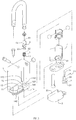
Fig. 2 is an exploded view of the lock of the present invention; -
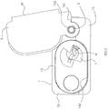
Fig. 3 is a bottom view when the slide is located at the first position; -
Fig. 4 is a cross sectional view, taken along line A-A inFig. 1 , while the slide is located at the first position; -
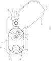
Fig. 5 is a bottom view when the slide is located at the second position; -
Fig. 6 is a cross sectional view of the lock when the slide is located at the second position; -
Fig. 7 is a bottom view when the slide is located at the third position; -
Fig. 8 is a cross sectional view of the lock when the slide is located at the third position; -
Fig. 9 is a bottom view of the second embodiment of the lock when the slide is located at the first position; -
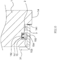
Fig. 10 is a cross sectional view at the concavity of the lock of the second embodiment of the lock when the slide is located at the first position; -
Fig. 11 is a bottom view of the second embodiment of the lock when the slide is located at the second position, and -
Fig. 12 is a cross sectional view at the concavity of the lock of the second embodiment of the lock when the slide is located at the second position. - Referring to
Figs. 1 to 6 , the lock of the present invention comprises ahousing 1 having aninstallation recess 11 and aninsertion hole 12 defined in the underside thereof. Aflat face 13 and aprotrusion 14 are formed on the underside of thehousing 1, wherein theprotrusion 14 is higher than theflat face 13 and has afirst end face 141. - A
pivot 2 is located in theinsertion hole 12 and has a first end and a second end. Aslide 3 is connected to the second end of thepivot 2. Theinstallation recess 11 has acore 4 received therein, and thecore 4 has akeyhole 41 which faces theslide 3. Thecore 4 is a fixed core or a replaceable core. - A
spring 5 is located in theinsertion hole 12 and applies a first resilient force toward theinsertion hole 12 and a second resilient force toward the direction that theslide 3 pivots. Thespring 5 is normally extended to form the first resilient force which tends to retract thespring 5. Thespring 5 is normally twisted to form the second resilient force which tends to rewind thespring 5 to its initial status. Thespring 5 is a compressible torsion spring to provide the first and second resilient forces. - The first end of the
spring 5 is fixed in theinsertion hole 12 and the second end of thespring 5 is connected to thepivot 2. In one embodiment, thespring 5 has afirst leg 51 on the first end thereof. Theinsertion hole 12 has aside hole 121 defined in the inside thereof. Thefirst leg 51 is fixed in theside hole 121 to fix thespring 5 to theinsertion hole 12. Thespring 5 has asecond leg 52 on the second end thereof. Thepivot 2 has aslot 21 defined in the first end thereof. Thesecond leg 52 is engaged with theslot 21 to fix thespring 5 to thepivot 2. - In one embodiment, in order to secure the
second leg 52 in theslot 21, theslot 21 includes aradial hole 22 defined radially in the first end thereof. Apin 23 extends through theradial hole 22. Thesecond leg 52 is restricted between the inner end of theslot 21 and thepin 23. - The
insertion hole 12 has anannular flange 122 extending from the inside thereof so as to define a throughhole 123 at the center of theannular flange 122. The throughhole 123 communicates with theinsertion hole 12. Thepivot 2 has acontact portion 24 extending radially from the second end thereof. Thepivot 2 extends through the throughhole 123. Thecontact portion 24 contacts the underside of theannular flange 122, and the first end of thespring 5 contacts the top of theannular flange 122. By the contact between thespring 5 and theannular flange 122, the first resilient force is maintained linearly. Thepivot 2 has astop ring 25 securely mounted to the first end thereof. Thestop ring 25 is a thin ring which contacts thespring 5 by its face instead of a point. Thestop ring 25 is located between the inner end of theslot 21 and thepin 23, so that thestop ring 25 is prevented from being disengaged from thepivot 2. - A
sleeve 6 is located in theinsertion hole 12 and receives thespring 5 therein to restrict thepin 23. Thesleeve 6 has atop portion 61 formed on the first end thereof which is located opposite to theslide 3. As shown inFig. 6 , thesleeve 6 restricts thepin 23 in theradial hole 22, and securely accommodates thepivot 2 and thespring 5 in thesleeve 6. The use of thesleeve 6 also makes the room in thehousing 1 be more efficiently used. As shown inFig. 4 , theinsertion hole 12 is adapted to receive one end of a shackle. By thetop portion 61 of thesleeve 6, the shackle and the spring of the shackle are separated from thepivot 2 and thespring 5, such that when locking or unlocking the lock, the shackle and the spring of the shackle do not interfere operation of thepivot 2 and thespring 5. The second end of thesleeve 6 includes twonotches 62 defined in the wall thereof. Thenotches 62 are located corresponding to thefirst leg 51 and theside hole 121 so that thefirst leg 51 extends through one of thenotches 62 and inserted into theside hole 121. - As shown in
Figs. 3 and4 , when the lock is not in use or under locked status, theslide 3 is positioned at the first position. Theslide 3 is not applied by any foreign force, the first resilient force applies to theslide 3 and positions theslide 3 on theflat face 13. Theslide 3 is applied by the second resilient force as well to cover theinstallation recess 11 to prevent rain, dust and other object from entering theinstallation recess 11 such that thecore 4 is not rusted and the life of use of the lock is prolonged. In order to ensure that theslide 3 covers theinstallation recess 11, in one embodiment, theprotrusion 14 has asecond end face 142. When the slide is positioned at the first position, one side of theslide 3 is applied by the second resilient face of thespring 5 and contacts thesecond end face 142 of theprotrusion 14 to ensure that theslide 3 covers theinstallation recess 11. In another embodiment, there is nosecond end face 142, theslide 3 includes awall 31 extending from one side thereof. Thewall 31 contacts the outside of thehousing 1 when theslide 3 is located at the first position. Theslide 3 is restricted as well. As shown in the present embodiment, theprotrusion 14 has thesecond end face 142 and theslide 3 has thewall 31. - When the user wants to unlock the lock, the user pivots the
slide 3 as shown inFigs. 5 and6 , theslide 3 overcomes the second resilient force and moves to the second position to make theslide 3 no cover thekeyhole 41. The user uses a key to insert into thekeyhole 41 to unlock the lock. It is noted that at least one portion of theslide 3 does not cover theinstallation recess 11. In other words, theslide 3 is not necessarily to move completely from theinstallation recess 11 of thecore 4, only thekeyhole 41 is exposed is sufficient for the user to unlock the lock. In one embodiment, theslide 3 is moved completely away from theinstallation recess 11 of thecore 4 for convenience of pick-up or replacement of thecore 4. In another embodiment, thefirst end face 141 is located such that when theslide 3 is positioned at the second position, theslide 3 contacts thefirst end face 141, so that the user can easily pivot theslide 3 to the second position. - In order to allow users to pivot the
slide 3 to the third position so s to replace thecore 4 or unlock the lock, as shown inFigs. 7 and8 , the user may apply a force to theslide 3, and thepivot 2 moves axially to compress andspring 5 and to overcome the first resilient force of thespring 5. Theslide 3 is located above thefirst end face 141 of theprotrusion 14 and can be continuously pivoted. At least one portion of theslide 3 does not cover theinstallation recess 11. Thekeyhole 41 is not covered so that the user can unlock the lock by using the key. When theslide 3 is located at the third position, at least one portion of theslide 3 does not cover theinstallation recess 11, and thecore 4 is completely not covered. - It is noted that a preferable embodiment of the present invention is equipped with a replaceable core. When the
slide 3 is positioned at the second position, theslide 3 is only required not to cover thekeyhole 41, and theslide 3 can partially cover thecore 4 to prevent thecore 4 from unintentionally picking out thecore 4 from thehousing 1. When theslide 3 is positioned at the third position, theslide 3 is completely away from thecore 4 so that the user can easily replace thecore 4. - As shown in
Figs. 9 to 12 , the second embodiment of the present invention is disclosed and the differences from the first embodiment are that theflat face 13 of thehousing 1 has aconcavity 15. Aresilient member 151, apositioning member 152 and arestriction member 153 are received in theconcavity 15. Therestriction member 153 has anopening 154. The positioningmember 152 has a narrowed engagingportion 155 which extends through theopening 154. As shown inFigs. 9 and10 , when theslide 3 is located at the first position, the engagingportion 155 is biased by theresilient member 151 and contacts theslide 3. As shown inFigs. 11 and12 , when theslide 3 is located at the second position, theslide 3 is located away from the engagingportion 155 which protrudes beyond theflat face 13. When the user stops to apply a force to theslide 3, and theslide 3 tends to move back to the first position, one side of theslide 3 is stopped by the engagingportion 155, so that the user does not need to continuously apply a force to theslide 3 and can unlock the lock easily and conveniently. - While we have shown and described the embodiment in accordance with the present invention, it should be clear to those skilled in the art that further embodiments may be made without departing from the scope of the present invention.
Claims (15)
- A lock comprising:a housing having an installation recess and an insertion hole defined in an underside thereof, a flat face and a protrusion formed on the underside of the housing, the protrusion being higher than the flat face and having a first end face;a pivot located in the insertion hole and having a first end and a second end, a slide connected to the second end of the pivot;a spring located in the insertion hole and applying a first resilient force toward the insertion hole and a second resilient force toward a direction that the slide pivots, a first end of the spring being fixed in the insertion hole and a second end of the spring connected to the pivot, andwhen the slide is located at a first position, the slide is applied by the first resilient force of the spring and located on the flat face, the slide is applied by the second resilient force of the spring to cover the installation recess, when the slide is located at a second position, the slide is pivoted to overcome the second resilient force of the spring and has at least one portion thereof not covering the installation recess, when the slide is located at a third position, the slide is pivoted and the pivot moves axially to compress and spring and to overcome the first resilient force of the spring, the slide is located above the first end face of the protrusion and continuously pivoted, and at least one portion of the slide does not cover the installation recess.
- The lock as claimed in claim 1, wherein the slide contacts the first end face when the slide is positioned at the second position.
- The lock as claimed in claim 1, wherein the spring has a first leg on the first end thereof, the insertion hole has a side hole defined in an inside thereof, the first leg is fixed in the side hole to fix the spring to the insertion hole.
- The lock as claimed in claim 3, wherein the spring has a second leg on the second end thereof, the pivot has a slot defined in the first end thereof, the second leg is engaged with the slot to fix the spring to the pivot.
- The lock as claimed in claim 4, wherein the slot includes a radial hole defined radially in the first end thereof, a pin extends through the radial hole, the second leg is restricted between an inner end of the slot and the pin.
- The lock as claimed in claim 5, wherein the pivot has a stop ring securely mounted to the first end thereof, the stop ring is located between the inner end of the slot and the pin.
- The lock as claimed in claim 5, wherein a sleeve is located in the insertion hole and receives the spring therein to restrict the pin, the sleeve has a top portion formed on a first end thereof which is located opposite to the slide, a second end of the sleeve includes two notches defined in a wall thereof, the notches are located corresponding to the first leg and the side hole.
- The lock as claimed in claim 7, wherein the insertion hole is adapted to receive one end of a shackle.
- The lock as claimed in claim 1-8, wherein the insertion hole has an annular flange extending from an inside thereof so as to define a through hole at a center of the annular flange, the through hole communicates with the insertion hole, the pivot has a contact portion extending radially from the second end thereof, the pivot extends through the through hole, the contact portion contacts an underside of the annular flange, the first end of the spring contacts a top of the annular flange.
- The lock as claimed in claim 1-8, wherein the protrusion has a second end face, the slide is applied by the second resilient face of the spring to contact the second end face of the protrusion when the slide is located at the first position.
- The lock as claimed in claim 1-8, wherein the slide includes a wall extending from one side thereof, the wall contacts an outside of the housing when the slide is located at the first position.
- The lock as claimed in claim 1-8, wherein the spring is a compressible torsion spring.
- The lock as claimed in claim 1-8, wherein the flat face of the housing has a concavity, a resilient member, a positioning member and a restriction member are received in the concavity, the restriction member has an opening, the positioning member has a narrowed engaging portion which extends through the opening, when the slide is located at the first position, the engaging portion is biased by the resilient member and contacts the slide, when the slide is located at the second position, the slide is located away from the engaging portion which protrudes beyond the flat face.
- The lock as claimed in claim 1-8, wherein the installation recess has a core received therein, the core has a keyhole which faces the slide, when the slide is located at the second position, the slide does not cover the keyhole, when the slide is located at the third position, the slide does not cover the core.
- The lock as claimed in claim 14, wherein the core is a fixed core or a replaceable core.
Applications Claiming Priority (1)
| Application Number | Priority Date | Filing Date | Title |
|---|---|---|---|
| US15/220,800 US9587416B1 (en) | 2016-07-27 | 2016-07-27 | Lock with a slide for covering lock core |
Publications (2)
| Publication Number | Publication Date |
|---|---|
| EP3276111A1 true EP3276111A1 (en) | 2018-01-31 |
| EP3276111B1 EP3276111B1 (en) | 2019-01-02 |
Family
ID=58162342
Family Applications (1)
| Application Number | Title | Priority Date | Filing Date |
|---|---|---|---|
| EP17159518.4A Active EP3276111B1 (en) | 2016-07-27 | 2017-03-07 | Lock with a slide for covering lock core |
Country Status (2)
| Country | Link |
|---|---|
| US (1) | US9587416B1 (en) |
| EP (1) | EP3276111B1 (en) |
Cited By (1)
| Publication number | Priority date | Publication date | Assignee | Title |
|---|---|---|---|---|
| SE545231C2 (en) * | 2021-12-21 | 2023-05-30 | Anchor Laas Ab | Method for protecting a padlock, and a padlock covering device |
Families Citing this family (2)
| Publication number | Priority date | Publication date | Assignee | Title |
|---|---|---|---|---|
| TWI563161B (en) * | 2015-10-08 | 2016-12-21 | Delta Electronics Inc | A door with hiding locks and a container having the door |
| US10934745B2 (en) * | 2019-01-16 | 2021-03-02 | Federal Lock Co., Ltd. | Core replaceable hockey lock |
Citations (6)
| Publication number | Priority date | Publication date | Assignee | Title |
|---|---|---|---|---|
| US2213814A (en) * | 1939-12-11 | 1940-09-03 | Briggs & Stratton Corp | Lock |
| US3422643A (en) * | 1967-10-19 | 1969-01-21 | Master Lock Co | Laminated padlocks with removable cylinder mechanisms |
| US3930391A (en) * | 1975-03-17 | 1976-01-06 | General Motors Corporation | Lock cylinder cover with key engagement release |
| US4192161A (en) * | 1978-09-18 | 1980-03-11 | General Motors Corporation | Escutcheon and cover assembly for a lock cylinder |
| US5718137A (en) * | 1996-08-30 | 1998-02-17 | Huston; Fred Michael | Fork lock cover |
| US7401484B1 (en) * | 2005-11-22 | 2008-07-22 | The Eastern Company | Low profile, lockable handle, housing and cover assembly |
Family Cites Families (35)
| Publication number | Priority date | Publication date | Assignee | Title |
|---|---|---|---|---|
| US1314306A (en) * | 1919-08-26 | Filler-cover | ||
| US2733831A (en) * | 1956-02-07 | Closure construction | ||
| US1369506A (en) * | 1918-04-29 | 1921-02-22 | Sargent & Co | Lock |
| US1517924A (en) * | 1923-08-03 | 1924-12-02 | American Hardware Corp | Lock |
| US1741093A (en) * | 1925-12-23 | 1929-12-24 | Briggs & Stratton Corp | Tumbler lock |
| US1904882A (en) * | 1929-04-20 | 1933-04-18 | August F W Viehweger | Burglarproof lock |
| US2343605A (en) * | 1940-03-11 | 1944-03-07 | Wise Solomon | Lock type fuel tank filling cap |
| US2355300A (en) * | 1942-01-22 | 1944-08-08 | Yale & Towne Mfg Co | Keyhole cover and assembly |
| US2388228A (en) * | 1944-05-25 | 1945-10-30 | Yale & Towne Mfg Co | Keyhole cover |
| US2400229A (en) * | 1945-05-12 | 1946-05-14 | Henry D Freeman | Lock |
| US2439978A (en) * | 1945-11-21 | 1948-04-20 | Anton W Konchan | Keyhole cover |
| US2562038A (en) * | 1950-01-30 | 1951-07-24 | Briggs & Stratton Corp | Cover for door locks |
| US2602319A (en) * | 1950-07-31 | 1952-07-08 | Briggs & Stratton Corp | Dust cover mounting for cylinder locks |
| US2702468A (en) * | 1951-05-05 | 1955-02-22 | Yale & Towne Mfg Co | Dust cover for locks |
| US2660877A (en) * | 1951-07-30 | 1953-12-01 | Abraham M Malouf | Keyhole cover for lock caps |
| US2931209A (en) * | 1958-07-23 | 1960-04-05 | Hurd Lock & Mfg Co | Keyhole cover for lock |
| US3898824A (en) * | 1974-08-21 | 1975-08-12 | Gen Motors Corp | Detented cover assembly for vehicle deck lid lock |
| US4290278A (en) * | 1979-09-25 | 1981-09-22 | Imperial Chemical Industries Limited | Machine for producing stitch bonded fabric |
| US4545223A (en) * | 1983-02-07 | 1985-10-08 | Oy Wartsila Ab | Padlock |
| US4587817A (en) * | 1984-05-29 | 1986-05-13 | The United States Of America As Represented By The Secretary Of The Navy | High security internal locking system |
| US4597274A (en) * | 1985-03-14 | 1986-07-01 | The D. L. Auld Company | Lock cover mechanism |
| US4586355A (en) * | 1985-03-28 | 1986-05-06 | General Motors Corporation | Lock cylinder cover with key engagement release of hold-open detent |
| JPH0330532Y2 (en) * | 1985-06-24 | 1991-06-27 | ||
| US4674308A (en) * | 1986-05-02 | 1987-06-23 | The D. L. Auld Company | Lock cover mechanism |
| IT211959Z2 (en) * | 1987-07-16 | 1989-05-25 | Alfa Lancia Ind | MOBILE COVERING DEVICE FOR THE LOCKING OF A CAR. |
| US5572890A (en) * | 1994-10-14 | 1996-11-12 | American Lock Company | High security lock system including cover plate |
| US6092404A (en) * | 1998-06-01 | 2000-07-25 | Intellikey Corporation | Electronically actuated cargo door lock assembly |
| US6272890B1 (en) * | 1999-08-27 | 2001-08-14 | Fred Michael Huston | Fork lock cover for motorcycle mounted with tape and method |
| US6408661B1 (en) * | 1999-09-14 | 2002-06-25 | Waterson Chen | Padlock assembly with a two-part U-shaped lock casing |
| US7225651B2 (en) * | 2001-07-02 | 2007-06-05 | Master Lock Company Llc | Pick-resistant wafer tumbler lock with sidebars |
| JP2008196224A (en) * | 2007-02-14 | 2008-08-28 | Tokai Rika Co Ltd | Key cylinder cover structure |
| JP4994953B2 (en) * | 2007-05-28 | 2012-08-08 | 朝日電装株式会社 | Ignition switch device |
| KR101078904B1 (en) * | 2007-05-28 | 2011-11-01 | 가부시끼 가이샤 구보다 | Ignition switch device |
| JP4994954B2 (en) * | 2007-05-28 | 2012-08-08 | 朝日電装株式会社 | Ignition switch device |
| US8474290B2 (en) * | 2009-12-03 | 2013-07-02 | Pioptima, Inc. | Locking handle and power module assembly |
-
2016
- 2016-07-27 US US15/220,800 patent/US9587416B1/en active Active
-
2017
- 2017-03-07 EP EP17159518.4A patent/EP3276111B1/en active Active
Patent Citations (6)
| Publication number | Priority date | Publication date | Assignee | Title |
|---|---|---|---|---|
| US2213814A (en) * | 1939-12-11 | 1940-09-03 | Briggs & Stratton Corp | Lock |
| US3422643A (en) * | 1967-10-19 | 1969-01-21 | Master Lock Co | Laminated padlocks with removable cylinder mechanisms |
| US3930391A (en) * | 1975-03-17 | 1976-01-06 | General Motors Corporation | Lock cylinder cover with key engagement release |
| US4192161A (en) * | 1978-09-18 | 1980-03-11 | General Motors Corporation | Escutcheon and cover assembly for a lock cylinder |
| US5718137A (en) * | 1996-08-30 | 1998-02-17 | Huston; Fred Michael | Fork lock cover |
| US7401484B1 (en) * | 2005-11-22 | 2008-07-22 | The Eastern Company | Low profile, lockable handle, housing and cover assembly |
Cited By (3)
| Publication number | Priority date | Publication date | Assignee | Title |
|---|---|---|---|---|
| SE545231C2 (en) * | 2021-12-21 | 2023-05-30 | Anchor Laas Ab | Method for protecting a padlock, and a padlock covering device |
| SE2151581A1 (en) * | 2021-12-21 | 2023-05-30 | Anchor Laas Ab | Method for protecting a padlock, and a padlock covering device |
| WO2023121536A1 (en) * | 2021-12-21 | 2023-06-29 | Anchor Lås AB | Method for protecting a padlock, and a padlock cover device |
Also Published As
| Publication number | Publication date |
|---|---|
| EP3276111B1 (en) | 2019-01-02 |
| US9587416B1 (en) | 2017-03-07 |
Similar Documents
| Publication | Publication Date | Title |
|---|---|---|
| JP4542129B2 (en) | Lock device for tent | |
| US9631398B1 (en) | Lock with a slide for covering lock core and positioning device for the slide | |
| US6997023B1 (en) | Combined combination lock and padlock | |
| US7131299B1 (en) | Combination lock and padlock combination with opening warning device | |
| US6792778B1 (en) | Combination lock | |
| US6578396B2 (en) | Removable cylindrical lock core | |
| US9228373B2 (en) | Combination-identifiable padlock | |
| EP3276111B1 (en) | Lock with a slide for covering lock core | |
| US7958757B1 (en) | Cam lock for a cabinet | |
| US20090301147A1 (en) | Compound lock | |
| US8584495B2 (en) | Exchangeable cylinder lock assembly | |
| US8707746B1 (en) | Lock with replaceable bottom pins | |
| US8393189B1 (en) | Tubular lock and a key for the same | |
| US20080072634A1 (en) | Door lock assembly having a support structure to support a tailpiece and a retaining plate | |
| US6698264B1 (en) | Core assembly for a lock | |
| US7434429B1 (en) | Automobile steering wheel lock | |
| CN111441673B (en) | Hidden latch hook padlock based on lock core is changed | |
| US4545225A (en) | Latch and lock assembly | |
| US1888828A (en) | Latch | |
| JPH0252752B2 (en) | ||
| CN219931870U (en) | Lock protector | |
| JP2542160B2 (en) | Locking device | |
| US20060021401A1 (en) | Tubular lock having two-stage operable latch bolt mechanism | |
| EP3048226A1 (en) | Lock cylinder replaceable padlock | |
| JP4495489B2 (en) | Thumb turn and lock |
Legal Events
| Date | Code | Title | Description |
|---|---|---|---|
| PUAI | Public reference made under article 153(3) epc to a published international application that has entered the european phase |
Free format text: ORIGINAL CODE: 0009012 |
|
| STAA | Information on the status of an ep patent application or granted ep patent |
Free format text: STATUS: REQUEST FOR EXAMINATION WAS MADE |
|
| 17P | Request for examination filed |
Effective date: 20170307 |
|
| AK | Designated contracting states |
Kind code of ref document: A1 Designated state(s): AL AT BE BG CH CY CZ DE DK EE ES FI FR GB GR HR HU IE IS IT LI LT LU LV MC MK MT NL NO PL PT RO RS SE SI SK SM TR |
|
| AX | Request for extension of the european patent |
Extension state: BA ME |
|
| GRAP | Despatch of communication of intention to grant a patent |
Free format text: ORIGINAL CODE: EPIDOSNIGR1 |
|
| STAA | Information on the status of an ep patent application or granted ep patent |
Free format text: STATUS: GRANT OF PATENT IS INTENDED |
|
| RIC1 | Information provided on ipc code assigned before grant |
Ipc: E05B 67/02 20060101AFI20180626BHEP Ipc: E05B 17/18 20060101ALN20180626BHEP Ipc: E05B 67/24 20060101ALI20180626BHEP Ipc: E05B 17/14 20060101ALI20180626BHEP |
|
| RIC1 | Information provided on ipc code assigned before grant |
Ipc: E05B 17/14 20060101ALI20180702BHEP Ipc: E05B 67/24 20060101ALI20180702BHEP Ipc: E05B 17/18 20060101ALN20180702BHEP Ipc: E05B 67/02 20060101AFI20180702BHEP |
|
| INTG | Intention to grant announced |
Effective date: 20180717 |
|
| GRAS | Grant fee paid |
Free format text: ORIGINAL CODE: EPIDOSNIGR3 |
|
| GRAA | (expected) grant |
Free format text: ORIGINAL CODE: 0009210 |
|
| STAA | Information on the status of an ep patent application or granted ep patent |
Free format text: STATUS: THE PATENT HAS BEEN GRANTED |
|
| AK | Designated contracting states |
Kind code of ref document: B1 Designated state(s): AL AT BE BG CH CY CZ DE DK EE ES FI FR GB GR HR HU IE IS IT LI LT LU LV MC MK MT NL NO PL PT RO RS SE SI SK SM TR |
|
| REG | Reference to a national code |
Ref country code: GB Ref legal event code: FG4D |
|
| REG | Reference to a national code |
Ref country code: CH Ref legal event code: EP Ref country code: AT Ref legal event code: REF Ref document number: 1084578 Country of ref document: AT Kind code of ref document: T Effective date: 20190115 |
|
| REG | Reference to a national code |
Ref country code: IE Ref legal event code: FG4D |
|
| REG | Reference to a national code |
Ref country code: DE Ref legal event code: R096 Ref document number: 602017001607 Country of ref document: DE |
|
| REG | Reference to a national code |
Ref country code: NL Ref legal event code: MP Effective date: 20190102 |
|
| REG | Reference to a national code |
Ref country code: LT Ref legal event code: MG4D |
|
| REG | Reference to a national code |
Ref country code: AT Ref legal event code: MK05 Ref document number: 1084578 Country of ref document: AT Kind code of ref document: T Effective date: 20190102 |
|
| PG25 | Lapsed in a contracting state [announced via postgrant information from national office to epo] |
Ref country code: NL Free format text: LAPSE BECAUSE OF FAILURE TO SUBMIT A TRANSLATION OF THE DESCRIPTION OR TO PAY THE FEE WITHIN THE PRESCRIBED TIME-LIMIT Effective date: 20190102 |
|
| PG25 | Lapsed in a contracting state [announced via postgrant information from national office to epo] |
Ref country code: NO Free format text: LAPSE BECAUSE OF FAILURE TO SUBMIT A TRANSLATION OF THE DESCRIPTION OR TO PAY THE FEE WITHIN THE PRESCRIBED TIME-LIMIT Effective date: 20190402 Ref country code: FI Free format text: LAPSE BECAUSE OF FAILURE TO SUBMIT A TRANSLATION OF THE DESCRIPTION OR TO PAY THE FEE WITHIN THE PRESCRIBED TIME-LIMIT Effective date: 20190102 Ref country code: PL Free format text: LAPSE BECAUSE OF FAILURE TO SUBMIT A TRANSLATION OF THE DESCRIPTION OR TO PAY THE FEE WITHIN THE PRESCRIBED TIME-LIMIT Effective date: 20190102 Ref country code: LT Free format text: LAPSE BECAUSE OF FAILURE TO SUBMIT A TRANSLATION OF THE DESCRIPTION OR TO PAY THE FEE WITHIN THE PRESCRIBED TIME-LIMIT Effective date: 20190102 Ref country code: ES Free format text: LAPSE BECAUSE OF FAILURE TO SUBMIT A TRANSLATION OF THE DESCRIPTION OR TO PAY THE FEE WITHIN THE PRESCRIBED TIME-LIMIT Effective date: 20190102 Ref country code: PT Free format text: LAPSE BECAUSE OF FAILURE TO SUBMIT A TRANSLATION OF THE DESCRIPTION OR TO PAY THE FEE WITHIN THE PRESCRIBED TIME-LIMIT Effective date: 20190502 Ref country code: SE Free format text: LAPSE BECAUSE OF FAILURE TO SUBMIT A TRANSLATION OF THE DESCRIPTION OR TO PAY THE FEE WITHIN THE PRESCRIBED TIME-LIMIT Effective date: 20190102 |
|
| PG25 | Lapsed in a contracting state [announced via postgrant information from national office to epo] |
Ref country code: LV Free format text: LAPSE BECAUSE OF FAILURE TO SUBMIT A TRANSLATION OF THE DESCRIPTION OR TO PAY THE FEE WITHIN THE PRESCRIBED TIME-LIMIT Effective date: 20190102 Ref country code: HR Free format text: LAPSE BECAUSE OF FAILURE TO SUBMIT A TRANSLATION OF THE DESCRIPTION OR TO PAY THE FEE WITHIN THE PRESCRIBED TIME-LIMIT Effective date: 20190102 Ref country code: RS Free format text: LAPSE BECAUSE OF FAILURE TO SUBMIT A TRANSLATION OF THE DESCRIPTION OR TO PAY THE FEE WITHIN THE PRESCRIBED TIME-LIMIT Effective date: 20190102 Ref country code: IS Free format text: LAPSE BECAUSE OF FAILURE TO SUBMIT A TRANSLATION OF THE DESCRIPTION OR TO PAY THE FEE WITHIN THE PRESCRIBED TIME-LIMIT Effective date: 20190502 Ref country code: BG Free format text: LAPSE BECAUSE OF FAILURE TO SUBMIT A TRANSLATION OF THE DESCRIPTION OR TO PAY THE FEE WITHIN THE PRESCRIBED TIME-LIMIT Effective date: 20190402 Ref country code: GR Free format text: LAPSE BECAUSE OF FAILURE TO SUBMIT A TRANSLATION OF THE DESCRIPTION OR TO PAY THE FEE WITHIN THE PRESCRIBED TIME-LIMIT Effective date: 20190403 |
|
| REG | Reference to a national code |
Ref country code: DE Ref legal event code: R097 Ref document number: 602017001607 Country of ref document: DE |
|
| PG25 | Lapsed in a contracting state [announced via postgrant information from national office to epo] |
Ref country code: AT Free format text: LAPSE BECAUSE OF FAILURE TO SUBMIT A TRANSLATION OF THE DESCRIPTION OR TO PAY THE FEE WITHIN THE PRESCRIBED TIME-LIMIT Effective date: 20190102 Ref country code: DK Free format text: LAPSE BECAUSE OF FAILURE TO SUBMIT A TRANSLATION OF THE DESCRIPTION OR TO PAY THE FEE WITHIN THE PRESCRIBED TIME-LIMIT Effective date: 20190102 Ref country code: AL Free format text: LAPSE BECAUSE OF FAILURE TO SUBMIT A TRANSLATION OF THE DESCRIPTION OR TO PAY THE FEE WITHIN THE PRESCRIBED TIME-LIMIT Effective date: 20190102 Ref country code: MC Free format text: LAPSE BECAUSE OF FAILURE TO SUBMIT A TRANSLATION OF THE DESCRIPTION OR TO PAY THE FEE WITHIN THE PRESCRIBED TIME-LIMIT Effective date: 20190102 Ref country code: RO Free format text: LAPSE BECAUSE OF FAILURE TO SUBMIT A TRANSLATION OF THE DESCRIPTION OR TO PAY THE FEE WITHIN THE PRESCRIBED TIME-LIMIT Effective date: 20190102 Ref country code: SK Free format text: LAPSE BECAUSE OF FAILURE TO SUBMIT A TRANSLATION OF THE DESCRIPTION OR TO PAY THE FEE WITHIN THE PRESCRIBED TIME-LIMIT Effective date: 20190102 Ref country code: CZ Free format text: LAPSE BECAUSE OF FAILURE TO SUBMIT A TRANSLATION OF THE DESCRIPTION OR TO PAY THE FEE WITHIN THE PRESCRIBED TIME-LIMIT Effective date: 20190102 Ref country code: EE Free format text: LAPSE BECAUSE OF FAILURE TO SUBMIT A TRANSLATION OF THE DESCRIPTION OR TO PAY THE FEE WITHIN THE PRESCRIBED TIME-LIMIT Effective date: 20190102 Ref country code: IT Free format text: LAPSE BECAUSE OF FAILURE TO SUBMIT A TRANSLATION OF THE DESCRIPTION OR TO PAY THE FEE WITHIN THE PRESCRIBED TIME-LIMIT Effective date: 20190102 |
|
| PLBE | No opposition filed within time limit |
Free format text: ORIGINAL CODE: 0009261 |
|
| STAA | Information on the status of an ep patent application or granted ep patent |
Free format text: STATUS: NO OPPOSITION FILED WITHIN TIME LIMIT |
|
| PG25 | Lapsed in a contracting state [announced via postgrant information from national office to epo] |
Ref country code: SM Free format text: LAPSE BECAUSE OF FAILURE TO SUBMIT A TRANSLATION OF THE DESCRIPTION OR TO PAY THE FEE WITHIN THE PRESCRIBED TIME-LIMIT Effective date: 20190102 Ref country code: LU Free format text: LAPSE BECAUSE OF NON-PAYMENT OF DUE FEES Effective date: 20190307 |
|
| 26N | No opposition filed |
Effective date: 20191003 |
|
| REG | Reference to a national code |
Ref country code: BE Ref legal event code: MM Effective date: 20190331 |
|
| PG25 | Lapsed in a contracting state [announced via postgrant information from national office to epo] |
Ref country code: SI Free format text: LAPSE BECAUSE OF FAILURE TO SUBMIT A TRANSLATION OF THE DESCRIPTION OR TO PAY THE FEE WITHIN THE PRESCRIBED TIME-LIMIT Effective date: 20190102 Ref country code: BE Free format text: LAPSE BECAUSE OF NON-PAYMENT OF DUE FEES Effective date: 20190331 |
|
| PG25 | Lapsed in a contracting state [announced via postgrant information from national office to epo] |
Ref country code: TR Free format text: LAPSE BECAUSE OF FAILURE TO SUBMIT A TRANSLATION OF THE DESCRIPTION OR TO PAY THE FEE WITHIN THE PRESCRIBED TIME-LIMIT Effective date: 20190102 |
|
| PG25 | Lapsed in a contracting state [announced via postgrant information from national office to epo] |
Ref country code: MT Free format text: LAPSE BECAUSE OF NON-PAYMENT OF DUE FEES Effective date: 20190307 |
|
| REG | Reference to a national code |
Ref country code: CH Ref legal event code: PL |
|
| PG25 | Lapsed in a contracting state [announced via postgrant information from national office to epo] |
Ref country code: LI Free format text: LAPSE BECAUSE OF NON-PAYMENT OF DUE FEES Effective date: 20200331 Ref country code: CH Free format text: LAPSE BECAUSE OF NON-PAYMENT OF DUE FEES Effective date: 20200331 |
|
| PG25 | Lapsed in a contracting state [announced via postgrant information from national office to epo] |
Ref country code: CY Free format text: LAPSE BECAUSE OF FAILURE TO SUBMIT A TRANSLATION OF THE DESCRIPTION OR TO PAY THE FEE WITHIN THE PRESCRIBED TIME-LIMIT Effective date: 20190102 |
|
| PG25 | Lapsed in a contracting state [announced via postgrant information from national office to epo] |
Ref country code: HU Free format text: LAPSE BECAUSE OF FAILURE TO SUBMIT A TRANSLATION OF THE DESCRIPTION OR TO PAY THE FEE WITHIN THE PRESCRIBED TIME-LIMIT; INVALID AB INITIO Effective date: 20170307 |
|
| PG25 | Lapsed in a contracting state [announced via postgrant information from national office to epo] |
Ref country code: MK Free format text: LAPSE BECAUSE OF FAILURE TO SUBMIT A TRANSLATION OF THE DESCRIPTION OR TO PAY THE FEE WITHIN THE PRESCRIBED TIME-LIMIT Effective date: 20190102 |
|
| PGFP | Annual fee paid to national office [announced via postgrant information from national office to epo] |
Ref country code: IE Payment date: 20230321 Year of fee payment: 7 Ref country code: FR Payment date: 20230331 Year of fee payment: 7 |
|
| PGFP | Annual fee paid to national office [announced via postgrant information from national office to epo] |
Ref country code: GB Payment date: 20230324 Year of fee payment: 7 Ref country code: DE Payment date: 20230307 Year of fee payment: 7 |
|
| PGFP | Annual fee paid to national office [announced via postgrant information from national office to epo] |
Ref country code: IE Payment date: 20240221 Year of fee payment: 8 |