JP4495489B2 - Thumb turn and lock - Google Patents

Thumb turn and lock Download PDF

Info

Publication number
JP4495489B2
JP4495489B2 JP2004071360A JP2004071360A JP4495489B2 JP 4495489 B2 JP4495489 B2 JP 4495489B2 JP 2004071360 A JP2004071360 A JP 2004071360A JP 2004071360 A JP2004071360 A JP 2004071360A JP 4495489 B2 JP4495489 B2 JP 4495489B2
Authority
JP
Japan
Prior art keywords
rotation
thumb turn
knob
knob member
lock
Prior art date
Legal status (The legal status is an assumption and is not a legal conclusion. Google has not performed a legal analysis and makes no representation as to the accuracy of the status listed.)
Expired - Fee Related
Application number
JP2004071360A
Other languages
Japanese (ja)
Other versions
JP2005256491A (en
Inventor
康雄 西
Current Assignee (The listed assignees may be inaccurate. Google has not performed a legal analysis and makes no representation or warranty as to the accuracy of the list.)
West Inx Ltd
Original Assignee
West Inx Ltd
Priority date (The priority date is an assumption and is not a legal conclusion. Google has not performed a legal analysis and makes no representation as to the accuracy of the date listed.)
Filing date
Publication date
Application filed by West Inx Ltd filed Critical West Inx Ltd
Priority to JP2004071360A priority Critical patent/JP4495489B2/en
Publication of JP2005256491A publication Critical patent/JP2005256491A/en
Application granted granted Critical
Publication of JP4495489B2 publication Critical patent/JP4495489B2/en
Anticipated expiration legal-status Critical
Expired - Fee Related legal-status Critical Current

Links

Images

Description

本発明は錠前および錠前に採用されるサムターンに関するものであり、特にサムターン回しと称される不正開錠を阻止可能なものに関する。   The present invention relates to a lock and a thumb turn employed for the lock, and more particularly to a device capable of preventing unauthorized unlocking referred to as a thumb turn.

従来より、摘み部材を回動させることによりロックボルトを出入りさせ、これにより施錠あるいは開錠を行う錠前が玄関の扉等に採用されている。錠前は、本体部分が扉内に埋め込まれ、扉の側面からデッドボルトを突出・退入可能なように固定されている。錠前を玄関先の扉の施錠に採用する場合は、扉の屋外側に錠前の施錠・開錠を行うためのシリンダー錠を設けると共に、屋内側に摘み部材が取り付けられている。   2. Description of the Related Art Conventionally, locks for locking and unlocking by using a lock bolt to move in and out by rotating a knob member have been adopted for entrance doors and the like. In the lock, the main body is embedded in the door and fixed so that the dead bolt can protrude and retract from the side of the door. When the lock is used for locking the door of the front door, a cylinder lock for locking and unlocking the lock is provided on the outdoor side of the door, and a knob member is attached on the indoor side.

デッドボルトは、シリンダー錠あるいは摘み部材を回動させることにより扉の側面から出入りするようになっている。扉が固定されている扉枠には、扉の側面から突出したデッドボルトを収納可能な収納部が設けられている。扉は、シリンダー錠や摘み部材を回動させ、デッドボルトを収納部に出入りさせることにより施錠状態あるいは開錠状態になる。   The dead bolt enters and exits from the side surface of the door by rotating a cylinder lock or a knob member. The door frame to which the door is fixed is provided with a storage portion that can store a dead bolt protruding from the side surface of the door. The door is brought into a locked state or an unlocked state by rotating the cylinder lock or the knob member and moving the dead bolt into and out of the storage portion.

一方、近年ドリル等で扉に穴を空けたり、扉と扉の取り付け枠との隙間から工具等を差し込み、摘み部材を回して不正開錠する、いわゆるサムターン回しという手口で家屋に侵入する犯罪が横行しており、社会的問題となっている。かかる問題を解決すべく、例えば下記特許文献1に示すように扉の摘み部材を囲む位置にサムターンカバーを設けることにより、いわゆるサムターン回しによる不正開錠を防止する方策が提案されている。   On the other hand, in recent years, there has been a crime to pierce a house with a technique called so-called thumb turn, in which a hole is drilled in the door with a drill, etc. It is rampant and has become a social problem. In order to solve this problem, for example, as shown in Patent Document 1 below, there has been proposed a measure for preventing unauthorized unlocking by so-called thumb turn by providing a thumb turn cover at a position surrounding a knob member of a door.

また、上記したサムターン回しによる不正開錠を防止すべく、下記特許文献2に示すような摘み部材を具備した錠前がある。特許文献2に開示されている摘み部材は、摘み部分が着脱可能であり、摘み部分を抜いておくことで不正開錠を防止するものである。
特開2003−056218号公報 特開平11−200678号公報
In addition, there is a lock provided with a knob member as shown in Patent Document 2 below in order to prevent unauthorized unlocking due to the thumb turn described above. The knob member disclosed in Patent Document 2 has a knob part that is detachable and prevents unauthorized unlocking by removing the knob part.
JP 2003-056218 A Japanese Patent Laid-Open No. 11-200678

上記特許文献1に開示されているように、摘み部材の周囲にサムターンカバーを設ければ、扉に穴を空けたりして工具等を差し込んでも、その工具が摘み部材に到達し難い。そのため、摘み部材を特許文献1に開示されているようなサムターンカバーで保護すれば、扉の不正開錠を防止することができる。   As disclosed in Patent Document 1, if a thumb turn cover is provided around the knob member, even if a tool or the like is inserted by opening a hole in the door, the tool hardly reaches the knob member. Therefore, if the knob member is protected by a thumb turn cover as disclosed in Patent Document 1, unauthorized opening of the door can be prevented.

しかし、上記したようにサムターンカバーを設ける場合、摘み部材の回動操作を行う度にサムターンカバーの蓋体を開ける必要がある。また、サムターンカバーで摘み部材を囲む場合、サムターンカバーで囲まれた領域内に指を入れて摘み部材の操作を行わねばならず、サムターンの操作が少なからず不自由になってしまう。さらに、サムターンカバーを設ける場合は、蓋体を閉じ忘れてしまうとサムターン回しに対する防犯効果が半減してしまうという問題点を有する。また、上記特許文献2のように摘み部材の摘み部分が着脱可能な構成とした場合も、摘み部分を抜き忘れてしまうとサムターン回しによる不正開錠に対する効果が全く発揮できないという問題がある。   However, when the thumb turn cover is provided as described above, it is necessary to open the thumb turn cover lid each time the knob member is rotated. In addition, when the knob member is surrounded by the thumb turn cover, the finger must be put in the area surrounded by the thumb turn cover to operate the knob member, which makes the thumb turn operation a little inconvenient. Furthermore, when providing the thumb turn cover, there is a problem that the crime prevention effect against the thumb turn is reduced by half if the lid is forgotten to close. In addition, even when the knob portion of the knob member is configured to be detachable as in Patent Document 2, there is a problem that if the knob portion is forgotten to be pulled out, the effect of illegal unlocking by turning the thumb turn cannot be exhibited at all.

かかる問題に鑑み、本発明は、通常時の施錠、開錠操作の操作性を維持しつつ、いわゆるサムターン回しに対処可能な防犯特性の高いサムターンおよび錠前の提供を目的とする。   In view of such a problem, an object of the present invention is to provide a thumb turn and a lock with high crime prevention characteristics that can cope with so-called thumb turn rotation while maintaining operability of normal locking and unlocking operations.

一般的にサムターン回しと称されるような不正開錠は、扉のサムターンが装着されている近傍の隙間や扉に開けた孔から工具等を差し込み、摘みに工具を引っ掛ける等して外力を作用させてサムターンの操作を行う手法で行われる。そのため、上記したような不正開錠が行われると、摘みを指で摘んでサムターンを通常に操作する場合とは異なり、摘み部材が移動する方向に大きな外力が作用する。 Unauthorized unlocking, commonly referred to as thumb-turn turning, applies external force by inserting a tool, etc., through a gap in the vicinity of the door where the thumb-turn is installed or a hole opened in the door, and hooking the tool to the knob. It is done by the technique of letting you operate the thumb turn. Therefore, when the above-described unauthorized unlocking is performed, a large external force acts in the direction in which the knob member moves , unlike the case where the thumb turn is normally operated by picking the knob with a finger.

そこで、かかる知見に基づいて提供される請求項1に記載の発明は、摘みと回転軸とを有し、所定方向に移動可能に支持された摘み部材と、当該摘み部材と一体的に回転する回転阻止手段と、当該回転阻止手段に対して近接離反可能な制動手段とを有し、回転阻止手段は、周壁部を有し、当該周壁部に係合部が設けられたものであり、制動手段は、回転阻止手段の係合部と係合可能な被係合部を有し、所定の制動回転軸を中心として回動するものであり、常時は、回転阻止手段の係合部と制動手段の被係合部とが係合不可能な位置にあり、回転軸の移動に伴って回転阻止手段の係合部が前記被係合部の回動領域に移動すると共に制動手段の被係合部が回転阻止手段に近接し、係合部と制動手段の被係合部とが係合して回転軸が回転不能に支持されることを特徴とするサムターンである。 Therefore, the invention according to claim 1 provided on the basis of such knowledge has a knob and a rotary shaft, and is supported integrally with the knob member movably supported in a predetermined direction, and rotates integrally with the knob member. A rotation preventing means and a braking means capable of approaching and moving away from the rotation preventing means. The rotation preventing means has a peripheral wall portion, and an engaging portion is provided on the peripheral wall portion. The means has an engaged part that can be engaged with the engaging part of the rotation preventing means, and rotates around a predetermined braking rotation axis. The engaging portion of the means is in a position where the engaging portion cannot be engaged, and the engaging portion of the rotation preventing means moves to the rotation region of the engaged portion along with the movement of the rotating shaft and the engaging portion of the braking means. The joint portion is close to the rotation prevention means, and the engaging portion and the engaged portion of the braking means are engaged to support the rotation shaft so that it cannot rotate. A thumb turn, characterized in that it is.

本発明のサムターンは、常時は回転阻止手段の係合部が制動手段の被係合部が移動する軌跡から外れた位置にある。そのため、本発明のサムターンは、通常に操作する限りは回転阻止手段が自由に回動可能な状態にあり、摘み部材を自由に操作できる。   In the thumb turn according to the present invention, the engagement portion of the rotation preventing means is always at a position deviated from the locus of movement of the engaged portion of the braking means. Therefore, in the thumb turn of the present invention, as long as it is normally operated, the rotation preventing means is in a freely rotatable state, and the knob member can be freely operated.

一方、本発明のサムターンは、サムターン回しのような不正開錠を試みようとして摘み部材に作用する外力により回転軸が移動すると、回転阻止手段が移動し、回転阻止手段の係合部が制動手段の被係合部と係合し、回転軸が回転不能となる。そのため、本発明によれば、摘み部材を不正操作するサムターン回しのような不正開錠に対する防犯特性に優れたサムターンを提供できる。 On the other hand, in the thumb turn of the present invention, when the rotation shaft is moved by an external force acting on the knob member in an attempt to perform unauthorized unlocking such as turning the thumb turn, the rotation prevention means moves, and the engagement portion of the rotation prevention means is the braking means. The rotating shaft becomes non-rotatable. Therefore, according to the present invention, it is possible to provide a thumb turn excellent in crime prevention characteristics against unauthorized unlocking such as a thumb turn turning operation of the knob member.

請求項2に記載の発明は、摘みと回転軸とを有し、所定方向に移動可能に支持された摘み部材と、当該摘み部材と一体的に回転する回転阻止手段と、当該回転阻止手段に対して近接離反可能な制動手段と、当該制動手段を回転阻止手段から離反させて離反構造を形成する離反手段とを有し、回転軸の移動に伴って前記離反構造が解除され、制動手段が、回転阻止手段に近接して回転阻止手段と係合し、回転軸が回転不能に支持されることを特徴とするサムターンである。 The invention according to claim 2 includes a knob member that has a knob and a rotation shaft and is supported so as to be movable in a predetermined direction, a rotation prevention means that rotates integrally with the knob member, and a rotation prevention means. In contrast, it has a braking means capable of approaching and separating, and a separating means for separating the braking means from the rotation preventing means to form a separating structure, and the separating structure is released as the rotating shaft moves , and the braking means is The thumb turn is characterized in that it is engaged with the rotation prevention means in the vicinity of the rotation prevention means and the rotation shaft is supported so as not to rotate.

本発明のサムターンは、回転軸が通常位置にある場合は、制動手段が回転阻止手段から離れた位置にあり、回転阻止手段が自由に回動可能な状態にある。そのため、本発明のサムターンは、摘みを摘んで通常の操作を行う限りは自由に操作することができる。   In the thumb turn of the present invention, when the rotation shaft is in the normal position, the braking means is located away from the rotation prevention means, and the rotation prevention means is in a freely rotatable state. Therefore, the thumb turn of the present invention can be freely operated as long as the knob is picked and a normal operation is performed.

一方、本発明のサムターンは、回転軸が移動すると開錠防止手段と制動手段の離反構造が解除されて制動手段が回転阻止手段に近接し、制動手段と回転阻止手段とが係合した状態となり、回転軸が回転不能となる。そのため、本発明のサムターンは、サムターン回しのような不正開錠を試みようとしても、摘み部材の回転軸が移動して回転不能となる。 On the other hand, in the thumb turn of the present invention, when the rotation shaft moves , the separation structure between the unlocking prevention means and the braking means is released, the braking means comes close to the rotation prevention means, and the braking means and the rotation prevention means are engaged. The rotation shaft becomes non-rotatable. Therefore, even if the thumb turn of the present invention tries to perform an unauthorized unlocking like a thumb turn, the rotation shaft of the knob member moves and becomes unable to rotate.

請求項3に記載の発明は、摘みと回転軸とを有し、所定方向に移動可能に支持された摘み部材と、当該摘み部材と一体的に回転する回転阻止手段と、当該回転阻止手段に対して近接離反可能な制動手段と、当該制動手段を回転阻止手段から離反した状態に支持して支持構造を形成する離反手段とを有し、回転阻止手段は、摘み部材の移動に伴って所定の軌跡に沿って移動するものであり、離反手段は、所定の位置にある回阻止手段の外周部に当接し前記軌跡を横切ることにより前記支持構造を形成し、当該支持構造は、回阻止手段の移動に伴って解除され、制動手段は、前記支持構造が解除されることを条件として回阻止手段に近接して係合し、摘み部材の回動を阻止することを特徴とするサムターンである。 According to a third aspect of the present invention, there is provided a knob member that has a knob and a rotation shaft and is supported so as to be movable in a predetermined direction, a rotation prevention means that rotates integrally with the knob member, and a rotation prevention means. The brake means capable of approaching and separating, and the separation means for supporting the brake means in a state separated from the rotation prevention means to form a support structure. The rotation prevention means is predetermined according to the movement of the knob member. is intended to move along a trajectory, away means forms the supporting structure by crossing the contact the track on the outer peripheral portion of the rotating blocking means is in place, the support structure, rotating is released with the movement of the blocking means, braking means engage close to the rotation prevention means on the condition that the support structure is released, characterized by blocking the rotation of the knob member It is a thumb turn.

一般的に、摘みを摘んで回転操作を行う限り、摘み部材の回転軸やこれと一体的に回転する回転阻止手段は移動せず、所定の位置で回転するものと想定される。本発明のサムターンは、摘み部材の回転軸が所定の位置にある場合、本発明のサムターンは、離反手段によって制動手段を回阻止手段から離された状態にあり、摘み部材を自由に回動させることが可能である。そのため、本発明のサムターンは、通常の行う限りは特別な操作を行わなくてもよく、操作性にすぐれている。 In general, as long as the knob is picked and rotated, the rotation shaft of the knob member and the rotation preventing means that rotates integrally with the knob do not move , but are assumed to rotate at a predetermined position. Thumb turn of the present invention, when the rotation shaft of the gripping member is in place, the thumb-turn of the present invention, in a state that release the braking means from rotation blocking means by separating means, freely rotating the knob member It is possible to make it. Therefore, the thumb turn according to the present invention does not require any special operation as long as it is normally performed, and is excellent in operability.

一方、不正開錠を試みようとして摘みを突き動かそうとすると、摘みには突き動かそうとする方向への外力が作用する。上記したように、本発明のサムターンは、摘み部材が所定方向に移動可能に支持されているため、この方向に外力が作用すると摘み部材やこれと一体的に回転する回転阻止手段が移動する。本発明のサムターンは回転阻止手段が移動すると支持構造が解除され、制動手段と回阻止手段とが係合状態になり、摘み部材が回転不可能となる。従って、本発明によればサムターン回しのような摘み部材に外力を作用させる手口の不正開錠を未然に防止できる。 On the other hand, when trying to push the knob in an attempt to illegally unlock, an external force in the direction in which the knob is pushed acts on the knob. As described above, in the thumb turn of the present invention, the knob member is supported so as to be movable in a predetermined direction. Therefore, when an external force is applied in this direction, the knob member and the rotation preventing means that rotates integrally with the knob member move . Thumb turn of the present invention is the rotation preventing means is canceled if you move the support structure, the braking means and the rotation prevention means is in the engaged state, the knob member becomes non-rotatable. Therefore, according to the present invention, it is possible to prevent unauthorized unlocking of the mouth and mouth that applies an external force to the knob member such as a thumb turn.

請求項4に記載の発明は、離反手段は、先端が制動手段に当接し、所定の回転中心を中心として回動自在な支持部を有し、当該支持部の中間部位において摘み部材の移動に伴って回転阻止手段が移動して形成される軌跡が交差することを特徴とする請求項3に記載のサムターンである。 According to a fourth aspect of the present invention, the separating means has a support portion whose tip is in contact with the braking means and is rotatable about a predetermined center of rotation, and is capable of moving the knob member at an intermediate portion of the support portion. 4. The thumb turn according to claim 3, wherein the trajectory formed by the movement of the rotation preventing means intersects.

本発明のサムターンにおいて、離反手段は、支持部が回動可能な状態で片持ち状に支持されており、その中間部分と回転阻止手段が移動して形成される軌跡とが交差するように配されている。そのため、本発明のサムターンでは、回阻止手段が僅かに移動するだけで制動手段に当接している先端が大きく移動する。従って、本発明のサムターンは、摘み部材を無理に押し回そうとして摘み部材が移動すると、離反手段が鋭敏に反応して支持構造が解除され、摘み部材が回動不可能となる。従って、本発明によれば、防犯特性が極めて優れたサムターンを提供できる。
請求項5に記載の発明は、制動手段および離反手段は、それぞれ回転阻止手段に近接する方向に所定の付勢力で付勢されており、制動手段に作用する付勢力は、離反手段に作用する付勢力よりも小さいことを特徴とする請求項2乃至4のいずれかに記載のサムターンである。
本発明のサムターンは、制動手段と離反手段の双方が付勢されており、回転阻止手段が所定の位置にある場合に制動手段を離反させるための離反手段を付勢する付勢力が、制動手段に対して作用する付勢力よりも大きい。そのため、本発明のサムターンは、回転阻止手段が所定の位置にある限りは制動手段と回転阻止手段が離反した状態を維持する。従って、本発明のサムターンは、不正開錠等により摘み部材が移動しない限り制動手段と回転阻止手段とが係合し、摘み部材が操作不能となるといったような誤作動が起こらない。
In the thumb turn according to the present invention, the separation means is supported in a cantilevered state with the support portion being rotatable, and is arranged so that the intermediate portion thereof intersects the locus formed by the movement of the rotation prevention means. Has been. Therefore, in thumb turn of the present invention, the tip rotating blocking means is in contact only with braking means slightly moves greatly moved. Accordingly, in the thumb turn of the present invention, when the picking member moves to forcefully push the picking member, the separating means reacts sensitively, the support structure is released, and the picking member cannot be rotated. Therefore, according to the present invention, it is possible to provide a thumb turn having extremely excellent crime prevention characteristics.
According to the fifth aspect of the present invention, the braking means and the separating means are each urged with a predetermined urging force in a direction close to the rotation preventing means, and the urging force acting on the braking means acts on the separating means. 5. The thumb turn according to claim 2, wherein the thumb turn is smaller than an urging force.
In the thumb turn of the present invention, both the braking means and the separating means are energized, and the energizing force for energizing the separating means for separating the braking means when the rotation preventing means is in a predetermined position is the braking means. It is larger than the urging force acting on. Therefore, the thumb turn of the present invention maintains the state where the braking means and the rotation prevention means are separated as long as the rotation prevention means is in a predetermined position. Therefore, the thumb turn of the present invention does not cause a malfunction such that the brake member and the rotation preventing unit are engaged with each other unless the knob member is moved by unauthorized unlocking or the like, and the knob member becomes inoperable.

請求項に記載の発明は、回転阻止手段は、所定の回転中心を中心として回転可能であり、回転阻止手段の移動に伴って突出部が侵入し、突出部の周方向への移動を阻止されることを特徴とする請求項1乃至のいずれかに記載のサムターンである。 Invention according to claim 6, rotation preventing means, Ri rotatable der around a rotation center of Jo Tokoro, the projecting portion can penetrate with the movement of rotation prevention means, in the circumferential direction of the protruding portion a thumb turn according to any one of claims 1 to 5, characterized in that it is prevented from moving.

本発明のサムターンは、不正開錠等に伴い摘み部材に対して外力が作用し、回転阻止手段が移動すると、突出部が侵入し、回転阻止手段の回動が不可能になる。そのため、本発明によれば、サムターン回しのような不正開錠に対する防犯特性に優れたサムターンを提供できる。 Thumb turn of the present invention act external force against the knob member due to unauthorized unlocking like, moving the rotation preventing means Then, protrusions enter City invasion, it becomes impossible rotation of the rotation preventing means. Therefore, according to the present invention, it is possible to provide a thumb turn excellent in crime prevention characteristics against unauthorized unlocking such as thumb turn.

ここで、上記請求項1乃至に記載のサムターンは、いずれもデッドボルト等の施錠片を動かす動作機構に接続されて使用されるものであり、錠前が施錠状態にある時に摘み部材に外力が作用して回転軸が移動することを利用して制動手段と回転阻止手段とを係合させ、摘み部材の回動を阻止するものである。そのため、上記請求項1乃至に記載のサムターンは、施工時に錠前が施錠状態にある時に回転阻止手段が所定の姿勢となり、摘み部が移動可能な方向に対して逆方向に外力を作用させても回転軸が回転しないように施工されないと防犯特性を十分に発揮できないおそれがある。 Here, the thumbturns according to claims 1 to 6 are all connected to an operating mechanism for moving a locking piece such as a dead bolt, and when the lock is in the locked state, an external force is applied to the knob member. The brake means and the rotation prevention means are engaged by utilizing the movement of the rotating shaft by acting to prevent the knob member from rotating. Therefore, in the thumb turn according to the first to sixth aspects, when the lock is in the locked state at the time of construction, the rotation preventing means is in a predetermined posture, and an external force is applied in a direction opposite to the direction in which the knob can move. However, there is a possibility that the crime prevention characteristic cannot be fully exhibited unless the rotation shaft is constructed so as not to rotate.

そこで、かかる知見に基づいて提供される1つの発明では、回転阻止手段が、外周部と、当該外周部から径方向外側に突出した突出部とを有し、所定の回転領域内の回転中心を中心として回転可能なように配置されており、前記回転領域内に、前記突出部の周方向への移動を阻止する移動阻止部が設けられている Accordingly, in one aspect of the invention that will be provided on the basis of this finding, the rotation preventing means, and the outer peripheral portion, and a protrusion protruding from the outer peripheral portion radially outward, the rotational center of the predetermined rotation region It is arranged so as to be rotatable as a center, and a movement blocking part for blocking the movement of the protruding part in the circumferential direction is provided in the rotation region .

このサムターンは、回転領域内に移動阻止部が突出しており、回転阻止手段の回転が規制される。そのため、このサムターンは、摘み部材を所定の姿勢で取り付けない限り摘み部材の操作ができない構成とし、施工者に対して摘み部材の取り付け姿勢が間違っていることを認識させることができる。従って、このサムターンによれば、摘み部材の取り付け間違いを防止し、防犯特性を確実に発揮可能なサムターンを提供できる。 In this thumb turn, the movement blocking portion protrudes in the rotation region, and the rotation of the rotation blocking means is restricted. Therefore, this thumb turn has a configuration in which the knob member cannot be operated unless the knob member is attached in a predetermined posture, and allows the installer to recognize that the attachment posture of the knob member is incorrect. Therefore, according to this thumb turn , it is possible to provide a thumb turn that can prevent a mistake in attaching the knob member and reliably exhibit the crime prevention characteristics.

また、同様の知見に基づいて提供される請求項7に記載の発明は、回転阻止手段は、外周部と、当該外周部から径方向外側に突出した突出部とを有し、所定の回転領域内の回転中心を中心として回転可能に配置されており、前記回転領域内には、摘み部材が移動可能な方向とは逆方向の成分を有する外力が摘み部材に作用した場合に突出部に当接し、回転阻止部材の回を阻止する移動阻止部が設けられていることを特徴とする請求項1乃至6のいずれかに記載のサムターンである。 In the invention according to claim 7, provided based on the same knowledge, the rotation preventing means includes an outer peripheral portion and a protruding portion protruding radially outward from the outer peripheral portion, and a predetermined rotation region. It is arranged so as to be rotatable around the center of rotation, and in the rotation region, when an external force having a component opposite to the direction in which the knob member can move acts on the knob member, contact a thumb turn according to any one of claims 1 to 6, characterized in that movement preventing portion for preventing the rotation of the rotation preventing member is provided.

本発明のサムターンは、摘み部材に対して所定の方向に外力が作用した場合に摘み部材と回転阻止手段とが所定方向に移動するが、これとは逆方向に外力が作用した場合は回転阻止手段の突出部が回転領域内に設けられた移動阻止部に当接し、摘み部材を回転させることができない。即ち、本発明のサムターンは、摘み部材を所定姿勢から一定方向(正方向)に回すことができるが、逆方向に回すことができない。そのため、本発明のサムターンは、万一取り付け施工時に摘み部材の取り付け姿勢を誤っても、施工後の動作確認時に摘み部材の取り付け姿勢の間違いに気が付く。従って、本発明によれば、摘み部材の取り付け姿勢を誤ることによる防犯特性の低下を未然に防止できる。 In the thumb turn of the present invention, when an external force is applied to the knob member in a predetermined direction, the knob member and the rotation prevention means move in a predetermined direction, but when an external force is applied in the opposite direction, the rotation prevention is performed. The protruding portion of the means abuts against the movement preventing portion provided in the rotation region, and the knob member cannot be rotated. That is, the thumb turn of the present invention can turn the knob from a predetermined posture in a certain direction (forward direction), but cannot turn it in the opposite direction. Therefore, the thumb turn of this invention notices the mistake of the attachment attitude | position of a knob member at the time of the operation confirmation after construction, even if the attachment attitude | position of a knob member is mistaken at the time of installation construction. Therefore, according to the present invention, it is possible to prevent the crime prevention characteristic from being deteriorated due to a wrong mounting posture of the knob member.

上記請求項1乃至7に記載のサムターンは、摘み部材が、回転軸と摘みとが偏心した位置関係にあるものであってもよい。(請求項8) In the thumb turn according to any one of claims 1 to 7, the knob member may be in a positional relationship in which the rotary shaft and the knob are eccentric. (Claim 8)

請求項9に記載の発明は、制動手段は、回阻止手段に近接する方向に付勢されていることを特徴とする請求項1乃至8のいずれかに記載のサムターンである。 The invention according to claim 9, the brake means is a thumb turn according to any one of claims 1 to 8, characterized in that it is biased in a direction toward the rotation preventing means.

かかる構成によれば、不正開錠により摘み部材が外力を受け、回転阻止手段が移動した際に直ちに回転阻止手段と付勢手段とを係合させ、摘み部材の回動を阻止することができる。 According to this configuration, when the knob member receives an external force due to unauthorized unlocking and the rotation prevention unit moves , the rotation prevention unit and the biasing unit are immediately engaged to prevent the knob member from rotating. .

請求項10に記載の発明は、施錠片を錠箱から出入りさせるための動作機構を有し、当該動作機構に請求項1乃至のいずれかに記載のサムターンが接続されていることを特徴とする錠前である。 The invention according to claim 10 has an operation mechanism for allowing the locking piece to enter and exit from the lock box, and the thumb turn according to any one of claims 1 to 9 is connected to the operation mechanism. Is a lock.

上記請求項1乃至に記載のサムターンは、いずれもサムターン回しのような手口で摘み部材を不正に操作しようとしても摘み部材がロック状態になり、回動操作が不能となる。そのため、本発明の錠前は、サムターン回しのような不正開錠に対する防犯性能が高い。 In any of the thumbturns according to the first to ninth aspects, even if an attempt is made to operate the knob member illegally by means of a thumb turn, the knob member is locked and cannot be rotated. Therefore, the lock of the present invention has a high crime prevention performance against unauthorized unlocking such as thumb turn.

本発明によれば、常時は通常の操作で施錠および開錠を行えると共に、サムターン回しと称されるような不正開錠を試みても開錠できない防犯特性に優れたサムターンおよび錠前を提供できる。   ADVANTAGE OF THE INVENTION According to this invention, while being able to lock and unlock normally by normal operation, the thumb turn and lock which were excellent in the crime prevention property which cannot be unlocked even if an illegal unlocking called a thumb turn is tried can be provided.

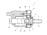
続いて、本発明の一実施形態であるサムターンについて図面を参照しながら詳細に説明する。図1は、本実施形態のサムターンを示す斜視図である。また、図2は、図1に示すサムターンの分解斜視図である。図3は、図1に示すサムターンの断面図である。図4〜図10は、それぞれ図1に示すサムターンの構成部品を示す図である。また、図11は、図1に示すサムターンの内部構造および動作を示す概念図である。図12は、図1に示すサムターンを備えた錠前の設置状態を示す斜視図である。図13は、図12に示す錠前において採用されている錠本体を示す斜視図である。図14は、図1に示すサムターンの変形例を示す概念図である。なお、以下の説明において上下の位置関係は、特に断りのない限りサムターンを図1等に示す姿勢で配置した状態を基準とする。   Next, a thumb turn which is an embodiment of the present invention will be described in detail with reference to the drawings. FIG. 1 is a perspective view showing a thumb turn according to the present embodiment. FIG. 2 is an exploded perspective view of the thumb turn shown in FIG. FIG. 3 is a sectional view of the thumb turn shown in FIG. 4 to 10 are diagrams showing components of the thumb turn shown in FIG. FIG. 11 is a conceptual diagram showing the internal structure and operation of the thumb turn shown in FIG. FIG. 12 is a perspective view showing an installed state of the lock provided with the thumb turn shown in FIG. FIG. 13 is a perspective view showing a lock body employed in the lock shown in FIG. FIG. 14 is a conceptual diagram showing a modification of the thumb turn shown in FIG. In the following description, the vertical positional relationship is based on the state in which the thumb turn is arranged in the posture shown in FIG. 1 and the like unless otherwise specified.

図1〜3において、1は本実施形態のサムターンである。サムターン1は、キャップ部材2の貫通孔3に挿通された摘み部材5を有する。貫通孔3は、図2や図4等に示すように略中央部から径方向外側(図2の状態において下方)に向けて僅かに偏心した位置まで延伸した形状を有する。そのため、摘み部材5は、貫通孔3の延伸方向、即ち図2に示す状態において上下方向に僅かに傾くことができる。また、貫通孔3の上方には、サムターン1のネジ止め用のネジ挿通孔4が設けられている。   1-3, 1 is the thumb turn of this embodiment. The thumb turn 1 has a knob member 5 inserted through the through hole 3 of the cap member 2. As shown in FIGS. 2 and 4, the through-hole 3 has a shape extending from a substantially central portion to a slightly eccentric position toward the radially outer side (downward in the state of FIG. 2). Therefore, the knob member 5 can be slightly tilted in the up-down direction in the extending direction of the through hole 3, that is, in the state shown in FIG. Further, a screw insertion hole 4 for screwing the thumb turn 1 is provided above the through hole 3.

摘み部材5は、金属製であり、摘み6と、回転軸8とが一体化された構成を有する。摘み6は、図2や図5のように扁平形状での摘み部7と接続軸10とを有する。摘み部7は、サムターン1の操作を行うために操作者が指で摘むための部分である。接続軸10は、図2のように摘み部7の中心位置から一端側に偏心した位置から突出しており、回転軸8が接続される部分である。接続軸10は、付け根部分にストッパー係合部11を有し、先端部分にピン孔12を有する。ストッパー係合部11は、円筒形の軸体の3面を面取りしたものであり、断面視が略「U」字形とされている。   The knob member 5 is made of metal and has a configuration in which the knob 6 and the rotary shaft 8 are integrated. The knob 6 has a flat knob 7 and a connecting shaft 10 as shown in FIGS. The knob portion 7 is a portion for an operator to pick with a finger in order to operate the thumb turn 1. As shown in FIG. 2, the connecting shaft 10 protrudes from a position eccentric to the one end side from the center position of the knob 7 and is a portion to which the rotating shaft 8 is connected. The connecting shaft 10 has a stopper engaging portion 11 at the base portion and a pin hole 12 at the tip portion. The stopper engaging portion 11 is formed by chamfering three surfaces of a cylindrical shaft body, and has a substantially “U” shape in cross-sectional view.

回転軸8は、図6に示すように一端側に摘み部材5の接続軸10の先端部分を挿通するための凹部13が形成されている。回転軸8には、凹部13を横断するように貫通したピン孔15が設けられている。回転軸8は、凹部13内に摘み部材5の接続軸10を挿通し、ピンをピン孔12,15に渡って挿通することによって摘み6と一体化される。回転軸8の先端部分には、周方向に等間隔に4つの溝16が形成され、正面視が略十文字となるように成形されている。   As shown in FIG. 6, the rotary shaft 8 has a recess 13 formed on one end side for inserting the tip of the connecting shaft 10 of the knob member 5. The rotation shaft 8 is provided with a pin hole 15 penetrating through the recess 13. The rotating shaft 8 is integrated with the knob 6 by inserting the connecting shaft 10 of the knob member 5 into the recess 13 and inserting the pin over the pin holes 12 and 15. Four grooves 16 are formed at equal intervals in the circumferential direction at the distal end portion of the rotating shaft 8 and are formed so that the front view is substantially cross-shaped.

キャップ部材2の内部には、ベース部材20が収納されている。また、ベース部材20には、それぞれベース部材20に対して独立的に回動可能にロックピース30、解除ピース40およびストッパー部材50が内蔵されている。   A base member 20 is housed inside the cap member 2. The base member 20 includes a lock piece 30, a release piece 40, and a stopper member 50 that can be independently rotated with respect to the base member 20.

ベース部材20は、図2に示すように外径がキャップ部材2の内径と略同一であり、円盤型の形状を有する。ベース部材20は、図7のように裏面側が平坦であるが、表面側はロックピース30や解除ピース40、ストッパー部材50が回動可能な空間を確保するために複雑な形状とされている。   As shown in FIG. 2, the base member 20 has an outer diameter substantially the same as the inner diameter of the cap member 2 and has a disk shape. The base member 20 has a flat back surface as shown in FIG. 7, but the front surface has a complicated shape to ensure a space in which the lock piece 30, the release piece 40, and the stopper member 50 can rotate.

ベース部材20の中心位置から僅かに径方向外側(図2に示す状態では下方)に偏心した位置には、略円形で回転軸8を挿通可能な軸挿通孔21と、二つの係止部22,22とが設けられている。軸挿通孔21は、キャップ部材2にベース部材20を納めた際に貫通孔3の下端側に相当する位置に形成されている。係止部22は、軸挿通孔21に連続した切り欠きであり、軸挿通孔21の上方に二つ並んでいる。係止部22は、軸挿通孔21の周部の上方から略垂直上方に切り込まれて形成されている。   A shaft insertion hole 21 through which the rotation shaft 8 can be inserted and two locking portions 22 are formed at a position slightly deviated radially outward (downward in the state shown in FIG. 2) from the center position of the base member 20. , 22 are provided. The shaft insertion hole 21 is formed at a position corresponding to the lower end side of the through hole 3 when the base member 20 is placed in the cap member 2. The locking portions 22 are notches that are continuous with the shaft insertion hole 21, and two locking portions 22 are arranged above the shaft insertion hole 21. The locking portion 22 is formed by cutting substantially vertically upward from above the peripheral portion of the shaft insertion hole 21.

軸挿通孔21の上方であって二つの係止部22,22の間には、膨出部25が設けられている。膨出部25は、ベース部材20の表面側に突出している。膨出部25には、キャップ部材2に収納した状態でキャップ部材2のネジ挿通孔4に連通するネジ挿通孔26aと、キャップ部材2に装着される裏板29をネジ止めするためのネジ孔26bとが設けられている。また、ベース部材20の下方、即ち係止部22,22や膨出部25とは反対側の位置には、ベース部材20の外周および軸挿通孔21の外周に沿う形状の周壁27が形成されている。また、周壁27の略中央部であって、膨出部25に対向する位置には、回転阻止片23が形成されている。回転阻止片23は、膨出部25と同様にベース部材20の表面側に突出すると共に、周壁27の内周面からベース部材20の径方向中央側(軸挿通孔21の内側)に突出している。   A bulging portion 25 is provided above the shaft insertion hole 21 and between the two locking portions 22 and 22. The bulging portion 25 protrudes to the surface side of the base member 20. In the bulging portion 25, a screw insertion hole 26 a communicating with the screw insertion hole 4 of the cap member 2 in a state of being accommodated in the cap member 2, and a screw hole for screwing the back plate 29 attached to the cap member 2 26b. Further, a peripheral wall 27 having a shape along the outer periphery of the base member 20 and the outer periphery of the shaft insertion hole 21 is formed below the base member 20, that is, at a position opposite to the locking portions 22 and 22 and the bulging portion 25. ing. Further, a rotation prevention piece 23 is formed at a position substantially in the center of the peripheral wall 27 and facing the bulging portion 25. The rotation prevention piece 23 protrudes to the surface side of the base member 20 similarly to the bulging portion 25, and protrudes from the inner peripheral surface of the peripheral wall 27 toward the radial center of the base member 20 (inside the shaft insertion hole 21). Yes.

周壁27の上方であって、軸挿通孔21の径方向外側の部位は、図7のように周壁27や膨出部25に相当する部位よりも肉薄に製作されており、ベース部材20をキャップ部材2に収納した際に、ロックピース30や解除ピース40を収容するためのピース収容空間Vとして機能する部分である。ピース収容空間Vのうち、回転阻止片23とベース部材20の中心とを結ぶ仮想線Lを境界として区画される一方側(図2では左側)の領域V1にはロックピース30を装着するための突起28aが設けられており、他方側(図2では右側)の領域V2には解除ピース40を装着するための突起28bが設けられている。突起28aは、ベース部材20の上方側であって、膨出部25に隣接する位置にある。また、突起28bは、軸挿通孔21の右方に隣接する位置に設けられている。   The part on the radial outside of the shaft insertion hole 21 above the peripheral wall 27 is made thinner than the part corresponding to the peripheral wall 27 and the bulging portion 25 as shown in FIG. This is a part that functions as a piece accommodating space V for accommodating the lock piece 30 and the release piece 40 when accommodated in the member 2. In the piece accommodating space V, a region V1 on one side (left side in FIG. 2) partitioned with a virtual line L connecting the rotation prevention piece 23 and the center of the base member 20 as a boundary is for mounting the lock piece 30 A projection 28a is provided, and a projection 28b for mounting the release piece 40 is provided in the region V2 on the other side (right side in FIG. 2). The protrusion 28 a is located on the upper side of the base member 20 and adjacent to the bulging portion 25. Further, the protrusion 28 b is provided at a position adjacent to the right side of the shaft insertion hole 21.

ロックピース30は、図2や図8のようにキャップ部材2の内周やベース部材20の外周に沿う形状に湾曲した外湾曲面31と、内湾曲面32とを有する部材である。ロックピース30の一端側には、突起28aを挿通するための軸孔33が形成されており、その先端側には先細り形状に突出した突出片35が形成されている。ロックピース30は、軸孔33に挿通された突起28aを中心としてベース部材20に対して回動自在に支持されている。   The lock piece 30 is a member having an outer curved surface 31 and an inner curved surface 32 which are curved in a shape along the inner circumference of the cap member 2 and the outer circumference of the base member 20 as shown in FIGS. A shaft hole 33 for inserting the protrusion 28a is formed on one end side of the lock piece 30, and a protruding piece 35 protruding in a tapered shape is formed on the tip end side thereof. The lock piece 30 is supported so as to be rotatable with respect to the base member 20 around a protrusion 28 a inserted through the shaft hole 33.

一方、ロックピース30の他端側には、内湾曲面32に対して交差する方向に突出したロック片36が形成されている。また、ロックピース30には、外湾曲面31に開口し、バネ37を装着するためのバネ装着穴38が形成されている。ロックピース30は、バネ装着穴38に装着されたバネ37によって外湾曲面31がキャップ部材2の内周面から離反する方向に付勢されている。   On the other hand, on the other end side of the lock piece 30, a lock piece 36 protruding in a direction intersecting the inner curved surface 32 is formed. In addition, the lock piece 30 is formed with a spring mounting hole 38 that opens to the outer curved surface 31 and for mounting the spring 37. The lock piece 30 is urged in a direction in which the outer curved surface 31 is separated from the inner peripheral surface of the cap member 2 by a spring 37 mounted in the spring mounting hole 38.

解除ピース40は、ロックピース30の動作のトリガーとして機能するものであり、図2や図9のように本体部41と、本体部41の中腹部分から本体部41に対して交差する方向に延伸した解除片43(支持部)とを有する。本体部41は、キャップ部材2の内周やベース部材20の外周に沿うように湾曲した外湾曲面45を有する。本体部41の一端側には、軸孔46が形成されている。解除ピース40は、軸孔46に突起28bを挿通することにより、突起28bを中心として回動自在に支持されている。   The release piece 40 functions as a trigger for the operation of the lock piece 30 and extends in a direction intersecting the main body 41 from the middle part of the main body 41 and the main body 41 as shown in FIGS. And the release piece 43 (support part). The main body 41 has an outer curved surface 45 that is curved along the inner circumference of the cap member 2 and the outer circumference of the base member 20. A shaft hole 46 is formed on one end side of the main body 41. The release piece 40 is rotatably supported around the protrusion 28b by inserting the protrusion 28b through the shaft hole 46.

本体部41の他端側には、外湾曲面45に開口し、バネ47を装着するためのバネ装着穴48が形成されている。解除ピース40は、バネ装着穴48に装着されたバネ47によって本体部41の他端側がキャップ部材2の内周面から離反する方向に付勢されている。   On the other end side of the main body 41, a spring mounting hole 48 that opens to the outer curved surface 45 and for mounting the spring 47 is formed. The release piece 40 is biased in a direction in which the other end side of the main body 41 is separated from the inner peripheral surface of the cap member 2 by a spring 47 mounted in the spring mounting hole 48.

ベース部材20の突起28bに解除ピース40を装着した状態において、解除片43は、ピース収容空間V内の領域V1,V2を横断し、先端が突起28aに装着されたロックピース30の内湾曲面32に届く長さとされている。上記したように、本体部41の下端側が突起28bを中心として回動可能なように支持されていると共に、上端側がバネ47によって付勢されているため、解除片43は、下方に付勢されている。そのため、解除片43は、軸挿通孔21に挿通された回転軸8に装着されているストッパー部材50の外周面に面接触している。   In a state where the release piece 40 is mounted on the protrusion 28b of the base member 20, the release piece 43 crosses the regions V1 and V2 in the piece accommodating space V, and the inner curved surface 32 of the lock piece 30 whose tip is mounted on the protrusion 28a. It is said that it reaches the length. As described above, the lower end side of the main body 41 is supported so as to be rotatable about the projection 28b, and the upper end side is biased by the spring 47, so that the release piece 43 is biased downward. ing. Therefore, the release piece 43 is in surface contact with the outer peripheral surface of the stopper member 50 attached to the rotary shaft 8 inserted through the shaft insertion hole 21.

ここで、解除ピース40を付勢しているバネ47は、ロックピース30を付勢しているバネ37よりも弾性力が強い。そのため、解除ピース40は、常時はロックピース30の内湾曲面32に当接してロックピース30をキャップ部材2の内壁面側に押しのけている。   Here, the spring 47 that biases the release piece 40 has a stronger elastic force than the spring 37 that biases the lock piece 30. Therefore, the release piece 40 is normally in contact with the inner curved surface 32 of the lock piece 30 to push the lock piece 30 toward the inner wall surface side of the cap member 2.

ストッパー部材50は、金属製で、略小判型の形状を有する部材であり、摘み6のストッパー係合部11に装着される部材である。ストッパー部材50は、ストッパー本体51と、このストッパー本体51の外周部分から上下方向に突出した突片部52,52とを有する。   The stopper member 50 is a member made of metal and having a substantially oval shape, and is a member attached to the stopper engaging portion 11 of the knob 6. The stopper member 50 includes a stopper main body 51 and projecting pieces 52 and 52 protruding in the vertical direction from the outer peripheral portion of the stopper main body 51.

ストッパー本体51は、図2のように厚み方向に2段形状の形状を有し、外接円の径の大きな大径部51aと、外接円の径が小さな小径部51bとを有する。ストッパー本体51の略中央部には、大径部51aおよび小径部51bを貫通する軸係合孔54が形成されている。軸係合孔54は、平面視が略「U」字形の貫通孔であり、摘み6のストッパー係合部11の外径に沿う形状とされている。   The stopper main body 51 has a two-stage shape in the thickness direction as shown in FIG. 2, and includes a large diameter portion 51a having a large circumscribed circle diameter and a small diameter portion 51b having a small circumscribed circle diameter. A shaft engaging hole 54 that penetrates the large-diameter portion 51a and the small-diameter portion 51b is formed in a substantially central portion of the stopper main body 51. The shaft engagement hole 54 is a through-hole having a substantially “U” shape in plan view, and has a shape along the outer diameter of the stopper engagement portion 11 of the knob 6.

大径部51aは、円弧状の周壁部53,53が対向すると共に、周壁部53,53の中間部分に周壁部53の外接円の中心方向に向けて窪んだ凹部55,55が設けられている。突片部52,52は、周壁部53,53の一端側(図10(a)において右側)、即ち凹部55,55の一方側から周壁部53の外接円の径方向に対して平行に突出している。大径部51aは、突片部52,52の外接円の半径rcが軸挿通孔21の内径riと略同一とされている。 The large-diameter portion 51a has arc-shaped peripheral wall portions 53 and 53 facing each other, and concave portions 55 and 55 that are recessed toward the center of the circumscribed circle of the peripheral wall portion 53 are provided in the middle portion of the peripheral wall portions 53 and 53. Yes. The projecting piece portions 52 and 52 protrude in parallel to the radial direction of the circumscribed circle of the peripheral wall portion 53 from one end side (right side in FIG. 10A) of the peripheral wall portions 53 and 53, that is, from one side of the concave portions 55 and 55. ing. In the large diameter portion 51 a, the radius rc 2 of the circumscribed circle of the projecting piece portions 52, 52 is substantially the same as the inner diameter ri of the shaft insertion hole 21.

小径部51bは、円弧状の周壁部56,56と、この周壁部56の外接円の径方向に対して水平な平坦部57,57とによって外形が形成された略小判状の部位である。周壁部56の外接円の半径rcは、軸挿通孔21の中心と回転阻止片23の内周面との距離rdと略同一である。 The small-diameter portion 51 b is a substantially oval portion having an outer shape formed by arc-shaped peripheral wall portions 56, 56 and flat portions 57, 57 that are horizontal with respect to the radial direction of the circumscribed circle of the peripheral wall portion 56. The radius rc 1 of the circumscribed circle of the peripheral wall portion 56 is substantially the same as the distance rd between the center of the shaft insertion hole 21 and the inner peripheral surface of the rotation prevention piece 23.

サムターン1は、キャップ部材2内に上記したベース部材20、ロックピース30、解除ピース40およびストッパー部材50を備えた不正開錠防止機構が納められており、この動作機構に摘み部材5が接続された構成を有する。即ち、サムターン1は、摘み部材5の動作に連動して不正開錠防止機構が動作する。   The thumb turn 1 includes an unauthorized unlocking prevention mechanism including the base member 20, the lock piece 30, the release piece 40, and the stopper member 50 in the cap member 2, and the knob member 5 is connected to the operation mechanism. Have a configuration. That is, in the thumb turn 1, the unauthorized unlocking prevention mechanism operates in conjunction with the operation of the knob member 5.

さらに具体的に説明すると、ベース部材20は、表面がキャップ部材2の開放端側に向き、軸挿通孔21の位置がキャップ部材2の貫通孔3に合致する姿勢として収納されている。キャップ部材2内に収納されたベース部材20の突起28aには、外湾曲面31がキャップ部材2の内周面側を向く姿勢でロックピース30が装着されている。ロックピース30のバネ装着穴38には、バネ37が装着されている。ロックピース30は、バネ37によりロック片36がキャップ部材2の中央側(軸挿通孔21側)に近接する方向に付勢されている。   More specifically, the base member 20 is housed in a posture in which the surface faces the open end side of the cap member 2 and the position of the shaft insertion hole 21 matches the through hole 3 of the cap member 2. A lock piece 30 is mounted on the protrusion 28 a of the base member 20 accommodated in the cap member 2 such that the outer curved surface 31 faces the inner peripheral surface of the cap member 2. A spring 37 is mounted in the spring mounting hole 38 of the lock piece 30. The lock piece 30 is urged by a spring 37 in a direction in which the lock piece 36 is close to the center side (the shaft insertion hole 21 side) of the cap member 2.

解除ピース40は、本体部41の外湾曲面45がキャップ部材2の内周面側を向き、解除片43がロックピース30側を向く姿勢としてベース部材20に装着されている。外湾曲面45に開口したバネ装着穴48には、バネ47が装着されている。解除ピース40は、バネ47の作用により本体部41の上端側がキャップ部材2の中心側に付勢され、解除片43が下方に付勢される。この状態において、解除片43は、先端部分43aがロックピース30の内湾曲面32に当接し、中間部分43bがストッパー部材50の周壁部56に外接した状態となっている。即ち、解除片43は、中間部分43bにおいて摘み部材5の偏心(移動)に伴って移動するストッパー部材50の軌跡と交差している。 The release piece 40 is attached to the base member 20 so that the outer curved surface 45 of the main body 41 faces the inner peripheral surface of the cap member 2 and the release piece 43 faces the lock piece 30 side. A spring 47 is mounted in the spring mounting hole 48 opened in the outer curved surface 45. In the release piece 40, the upper end side of the main body 41 is biased toward the center side of the cap member 2 by the action of the spring 47, and the release piece 43 is biased downward. In this state, the release piece 43 is in a state in which the distal end portion 43 a abuts on the inner curved surface 32 of the lock piece 30 and the intermediate portion 43 b circumscribes the peripheral wall portion 56 of the stopper member 50. That is, the release piece 43 intersects the locus of the stopper member 50 that moves with the eccentricity (movement) of the knob member 5 at the intermediate portion 43b.

上記したようにしてベース部材20に対してロックピース30と解除ピース40を装着した状態において、キャップ部材2の外側から摘み6が貫通孔3および軸挿通孔21に挿通され、装着されている。この状態において、摘み6の接続軸10およびストッパー係合部11は、ピース収容空間V内に露出する。摘み6のストッパー係合部11には、キャップ部材2の開放端側からストッパー部材50が大径部51aを内側(ベース部材20側)に向けた姿勢で装着されている。摘み6に対してストッパー部材50が装着された状態において、大径部51aは軸挿通孔21内に納まっており、小径部51bの周壁部56が回転阻止片23の内周面に面接触した状態となっている。この状態において、摘み6は、ベース部材20に対して回動自在に支持された状態となっている。   In the state where the lock piece 30 and the release piece 40 are attached to the base member 20 as described above, the knob 6 is inserted through the through hole 3 and the shaft insertion hole 21 from the outside of the cap member 2 and attached. In this state, the connection shaft 10 and the stopper engaging portion 11 of the knob 6 are exposed in the piece accommodating space V. A stopper member 50 is mounted on the stopper engaging portion 11 of the knob 6 from the open end side of the cap member 2 in such a posture that the large diameter portion 51a faces inward (base member 20 side). In a state where the stopper member 50 is attached to the knob 6, the large diameter portion 51 a is accommodated in the shaft insertion hole 21, and the peripheral wall portion 56 of the small diameter portion 51 b is in surface contact with the inner peripheral surface of the rotation prevention piece 23. It is in a state. In this state, the knob 6 is in a state of being rotatably supported with respect to the base member 20.

摘み6は、キャップ部材2の内部空間に突出した接続軸10が回転軸8の凹部13に差し込まれ、回転軸8に接続されている。摘み6は、ピン孔12,15にわたって打ち込まれたピンによって一体化されている。   The knob 6 is connected to the rotary shaft 8 by inserting the connecting shaft 10 protruding into the internal space of the cap member 2 into the recess 13 of the rotary shaft 8. The knob 6 is integrated by a pin driven over the pin holes 12 and 15.

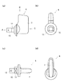
サムターン1は、図12のように扉62内に取り付けられた錠本体61内の動作機構に回転軸8を介して接続され、錠前60を形成している。錠前60は、従来公知の錠前と同様に、錠本体61内にデッドボルト63(施錠片)およびラッチ65を出入りさせるための動作機構(図示せず)を内蔵している。錠前60は、扉62に取り付けられたサムターン1あるいはシリンダー錠66に接続されている。シリンダー錠66は、従来公知のものと同様の構成を有し、鍵穴に鍵を差し込んで回転させると、これに連動して背面側に突出した舌片69が回転するものである。錠前60は、サムターン1を操作して回転軸8を回転させるか、シリンダー錠66に差し込まれた鍵の操作により舌片69を回転させることにより施錠開錠操作することができる。   The thumb turn 1 is connected to an operation mechanism in the lock body 61 attached in the door 62 as shown in FIG. 12 via the rotary shaft 8 to form a lock 60. The lock 60 incorporates an operating mechanism (not shown) for allowing the dead bolt 63 (locking piece) and the latch 65 to enter and exit from the lock body 61 as in the case of a conventionally known lock. The lock 60 is connected to the thumb turn 1 or the cylinder lock 66 attached to the door 62. The cylinder lock 66 has the same structure as a conventionally known one, and when a key is inserted into the keyhole and rotated, a tongue piece 69 protruding to the back side rotates in conjunction with this. The lock 60 can be unlocked by operating the thumb turn 1 to rotate the rotating shaft 8 or rotating the tongue piece 69 by operating a key inserted into the cylinder lock 66.

錠本体61は、図13に示すように、正面67および背面68に2つの開口部70,71を有する。開口部70には、上記した動作機構の一部であり、サムターン1の回転軸8およびシリンダー錠66の舌片69と係合する係合部74が露出している。デッドボルト63は、回転軸8や舌片69の回動に連動して錠本体61の側面72から出入りする。また、開口部71には、上記した動作機構の一部を構成する角穴73が露出している。角穴73は、ドアハンドル75の支軸となる角芯76が挿通されるものである。 As shown in FIG. 13 , the lock body 61 has two openings 70 and 71 on the front surface 67 and the back surface 68. In the opening 70, an engaging portion 74 that is a part of the above-described operation mechanism and engages with the rotating shaft 8 of the thumb turn 1 and the tongue piece 69 of the cylinder lock 66 is exposed. The dead bolt 63 enters and exits from the side surface 72 of the lock body 61 in conjunction with the rotation of the rotary shaft 8 and the tongue piece 69. Further, a square hole 73 that constitutes a part of the above-described operation mechanism is exposed in the opening 71. The square hole 73 is for inserting a square core 76 as a support shaft of the door handle 75.

錠前60は、図12に示すように錠本体61を扉62内に埋設して使用される。錠本体61は、側面72が扉62の側面77側を向き、デッドボルト63およびラッチ65が側面72,77から突出可能なように設置される。また、扉62の正面78および背面80には、それぞれ錠本体61の開口部70,71に相当する位置に取り付け孔81,82が窄孔されている。   The lock 60 is used by embedding a lock body 61 in a door 62 as shown in FIG. The lock body 61 is installed such that the side surface 72 faces the side surface 77 side of the door 62 and the dead bolt 63 and the latch 65 can protrude from the side surfaces 72 and 77. Further, attachment holes 81 and 82 are formed in the front surface 78 and the back surface 80 of the door 62 at positions corresponding to the openings 70 and 71 of the lock body 61, respectively.

扉62には、取り付け孔82および開口部71を貫通するように角芯76が挿通され、この角芯76の両端にドアハンドル75が固定されている。ドアハンドル75を回動させると、これに連動して錠前60のラッチ65が扉62の側面77から出入りする。   A square core 76 is inserted into the door 62 so as to pass through the attachment hole 82 and the opening 71, and door handles 75 are fixed to both ends of the square core 76. When the door handle 75 is rotated, the latch 65 of the lock 60 enters and exits from the side surface 77 of the door 62 in conjunction with this rotation.

扉62の背面80側に設けられた取り付け孔81には、図12のようにシリンダー錠66が装着されている。シリンダー錠66は、鍵穴(図示せず)のある正面側を外側に向け、背面側の舌片69を係合部74に係合させて固定されている。そのため、シリンダー錠66に鍵を挿入して回動させると、これに連動して錠本体61内の動作機構が作動し、扉62の側面77からデッドボルト63が出入りする。   A cylinder lock 66 is mounted in the mounting hole 81 provided on the back surface 80 side of the door 62 as shown in FIG. The cylinder lock 66 is fixed with the front side with a keyhole (not shown) facing outward and the tongue piece 69 on the back side engaged with the engaging portion 74. Therefore, when the key is inserted into the cylinder lock 66 and rotated, the operation mechanism in the lock body 61 is operated in conjunction with this, and the dead bolt 63 enters and exits from the side surface 77 of the door 62.

一方、扉62の正面78側に設けられた取り付け孔81には、図3や図12のように台座85にキャップ部材2をネジ止めすることによりサムターン1が固定されている。サムターン1は、通常の施錠時は図11,12のように、扁平形状の摘み部7が水平に倒れた状態が施錠状態となるように施工されている。即ち、サムターン1は、施錠状態とした時に摘み部7の延伸方向と、摘み部材5およびこれに装着されたストッパー部材50の摺動方向(偏心方向、移動方向)とが交差するように摘み部材5が装着されている。 On the other hand, the thumb turn 1 is fixed to the mounting hole 81 provided on the front surface 78 side of the door 62 by screwing the cap member 2 to the pedestal 85 as shown in FIGS. The thumb turn 1 is constructed so that the state in which the flat knob 7 is tilted horizontally becomes a locked state as shown in FIGS. That is, the thumb turn 1 has a knob member so that the extending direction of the knob portion 7 and the sliding direction (eccentric direction , moving direction ) of the knob member 5 and the stopper member 50 attached thereto cross when the thumb turn 1 is locked. 5 is installed.

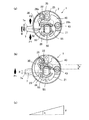
続いて、本実施形態のサムターン1および錠前60の動作について図面を参照しながら詳細に説明する。錠前60が施錠状態にあるとき、サムターン1は、摘み部材5に装着されたストッパー部材50の大径部51aが軸挿通孔21内に収納されると共に、小径部51bが軸挿通孔21側に突出した係止部22の内周面と解除ピース40の解除片43とに面接触し、挟まれた状態となっている。また、この状態では、ストッパー部材50は、凹部55,55のうちのいずれか一方がロックピース30側を向く姿勢とされている。   Next, operations of the thumb turn 1 and the lock 60 according to this embodiment will be described in detail with reference to the drawings. When the lock 60 is in the locked state, the thumb turn 1 is configured such that the large-diameter portion 51a of the stopper member 50 attached to the knob member 5 is accommodated in the shaft insertion hole 21 and the small-diameter portion 51b is on the shaft insertion hole 21 side. The protruding inner surface of the locking portion 22 and the release piece 43 of the release piece 40 are in surface contact and sandwiched. In this state, the stopper member 50 is in a posture in which one of the recesses 55 and 55 faces the lock piece 30 side.

図11(a)のように摘み部7が水平な状態(施錠状態)で摘み部7を摘んで矢印A方向に回動させると、これに連動してストッパー部材50がキャップ部材2内で回動する。この時、解除ピース40の解除片43は、ストッパー部材50の小径部51bの周囲に面接触した状態であり、ロックピース30をキャップ部材2の内周壁側に押しつけたままである。そのため、サムターン1は、摘み部7を摘んで回す限りは特別な操作を行わずに開錠状態にすることができる。   When the knob 7 is picked and rotated in the direction of arrow A with the knob 7 in a horizontal state (locked state) as shown in FIG. 11A, the stopper member 50 rotates in the cap member 2 in conjunction with this. Move. At this time, the release piece 43 of the release piece 40 is in surface contact with the periphery of the small diameter portion 51 b of the stopper member 50, and the lock piece 30 is pressed against the inner peripheral wall side of the cap member 2. Therefore, as long as the thumb turn 1 is picked and turned, the thumb turn 1 can be unlocked without performing any special operation.

一方、サムターン回しと称するような不正開錠を試みるべく摘み部7を突き上げるような外力F1が作用すると、この外力F1によって摘み部材5は摘み部7側が上方に持ち上がって傾き、軸心位置が偏心(移動)する。これにより、摘み部7に近い位置に装着されているストッパー部材50は、図11(b)に示すように上方に持ち上がる。 On the other hand, when an external force F1 that pushes up the knob portion 7 to try to perform unauthorized unlocking, which is called thumb turn, acts, the knob member 5 is tilted upward by the knob portion 7 side by this external force F1, and the axial center position is eccentric. (Move) . Thereby, the stopper member 50 mounted at a position close to the knob 7 is lifted upward as shown in FIG.

ストッパー部材50が上方に移動すると、これに連動して小径部51bの周部に面接触している解除ピース40の解除片43が突起28bを中心として回動し、上方に傾く。解除片43が傾くと、この解除片43が図11(a)に矢印rで示すように上方に持ち上がる。これにより、ロックピース30は、解除片43がロックピース30の内湾曲面32に当接して構成されていた支持構造が解除される。バネ37による付勢力が作用して軸孔33に挿通された突起28aを中心として回動し始め、ロック片36がキャップ部材2の中央側に移動すると共に、図11(a)のように解除片43の先端がロックピース30の突出片35に突き当たり、カム的な作用によりロックピース30のロック片36がさらにストッパー部材50側に近づく。 When the stopper member 50 is moved upward, the release piece 43 of the release piece 40 that is in surface contact with the peripheral portion of the small diameter portion 51b is rotated about the protrusion 28b and tilted upward. When the release piece 43 is inclined, the release piece 43 is lifted upward as indicated by an arrow r in FIG. As a result, the lock piece 30 is released from the support structure in which the release piece 43 is configured to abut against the inner curved surface 32 of the lock piece 30. The urging force of the spring 37 acts to start rotating around the protrusion 28a inserted through the shaft hole 33, and the lock piece 36 moves to the center side of the cap member 2 and is released as shown in FIG. The tip of the piece 43 abuts against the protruding piece 35 of the lock piece 30, and the lock piece 36 of the lock piece 30 further approaches the stopper member 50 side by a cam action.

摘み部材5が外力の影響を受けて移動すると、施錠状態においてストッパー部材50の大径部51aの上方から突出している突片部52がベース部材20の軸挿通孔21に連続する係止部22内に侵入する。この状態になると、ストッパー部材50の凹部55が、ロックピース30のロック片36が侵入可能な位置にある。そのため、ロックピース30のロック片36は、バネ37による付勢力の影響と、上記したカム的な作用によって回動し、凹部55内に侵入する。これにより、ストッパー部材50および摘み部材5が回動不可能な状態となる。 When the knob member 5 is moved under the influence of an external force, the protruding portion 52 protruding from above the large-diameter portion 51a of the stopper member 50 in the locked state is a locking portion 22 that is continuous with the shaft insertion hole 21 of the base member 20. Invade inside. In this state, the recess 55 of the stopper member 50 is in a position where the lock piece 36 of the lock piece 30 can enter. Therefore, the lock piece 36 of the lock piece 30 is rotated by the influence of the urging force of the spring 37 and the above-described cam action and enters the recess 55. Thereby, the stopper member 50 and the knob member 5 are brought into a state in which they cannot rotate.

摘み部7の移動した位置に作用している外力が解除されると、解除ピース40を上方に持ち上げる力がなくなる。また、ロックピース30を付勢しているバネ37の弾性力は、解除ピース40を付勢しているバネ47の弾性力よりも小さい。そのため、外力の作用が無くなると、バネ47の作用によって解除ピース40の解除片43が下方に移動し、ロックピース30の内湾曲面32を突き動かす。これにより、ロックピース30は、突起28aを中心として回動し、ロック片36がストッパー部材50の凹部55から抜ける。その後、ストッパー部材50およびこれに接続されている摘み部材5は、姿勢が水平に戻り、回動自在な状態に戻る。 When the external force acting on the position where the knob 7 is moved is released, the force to lift the release piece 40 upward is lost. Further, the elastic force of the spring 37 urging the lock piece 30 is smaller than the elastic force of the spring 47 urging the release piece 40. Therefore, when the action of the external force disappears, the release piece 43 of the release piece 40 moves downward by the action of the spring 47 and pushes the inner curved surface 32 of the lock piece 30. As a result, the lock piece 30 rotates around the protrusion 28 a and the lock piece 36 comes out of the recess 55 of the stopper member 50. Thereafter, the stopper member 50 and the knob member 5 connected thereto return to a horizontal state and return to a rotatable state.

上記したサムターン1は、摘み部材5を無理に上方に持ち上げようとする力を受けてロックピース30、解除ピース40およびストッパー部材50を有する動作機構が作動し、摘み部材5の回動を阻止するものである。そのため、サムターン1は、万一誤った取り付け姿勢で取り付けられ、摘み部7を下方(図11(a)においてB方向)に回すことにより開錠状態となるように取り付けられてしまうと動作機構が働かず、防犯特性を発揮できない。そこで、かかる施工間違いを防止すべく、本実施形態のサムターン1は、ストッパー部材50の大径部51aの外周部に突片部52,52を設けると共に、大径部51aが軸挿通孔21内に納まった状態で回動させ摘み部7を水平な姿勢とした際に突片部52に突き当たる位置に回転阻止片23を設けた構成としている。そのため、本実施形態のサムターン1は、回転軸8を中心とする水平位置よりも下方に回転させることができない。従って、万一施工間違いにより摘み部7が水平位置にある時に開錠状態となるように取り付けられても、摘み部7が操作不能であり、施工間違いに気が付く。   In the thumb turn 1 described above, the operating mechanism having the lock piece 30, the release piece 40 and the stopper member 50 is actuated by receiving a force forcibly lifting the knob member 5 upward to prevent the knob member 5 from rotating. Is. Therefore, if the thumb turn 1 is attached with an incorrect attachment posture, and if it is attached so as to be unlocked by turning the knob 7 downward (B direction in FIG. 11A), the operating mechanism is It does not work and cannot exhibit crime prevention characteristics. Therefore, in order to prevent such a construction error, the thumb turn 1 of the present embodiment is provided with projecting pieces 52, 52 on the outer peripheral portion of the large diameter portion 51a of the stopper member 50, and the large diameter portion 51a is located in the shaft insertion hole 21. The rotation prevention piece 23 is provided at a position where it comes into contact with the protruding piece portion 52 when the knob 7 is rotated in a state where it is housed in a horizontal posture. For this reason, the thumb turn 1 of the present embodiment cannot be rotated below the horizontal position around the rotation shaft 8. Therefore, even if the knob portion 7 is attached so as to be unlocked when the knob portion 7 is in the horizontal position due to an installation error, the knob portion 7 cannot be operated, and the operator will notice the installation error.

上記したように、サムターン1は、不正開錠を試みようとして摘みに無理な外力F1を作用させると、回転軸8が傾き、これに装着されたストッパー部材50が外力の作用する方向に移動する。これにより、ストッパー部材50が、小径部51bの周壁部56に当接していた解除ピース40の解除片43を押しのけ、解除ピース40がロックピース30の内湾曲面32に当接して構成されていた支持構造が解除されると共に、ロックピース30のロック片36とストッパー部材50の凹部55とが係合して摘み部材5が回転不能となる。 As described above, when the thumb turn 1 applies an unreasonable external force F1 to try to unlock it, the rotation shaft 8 is tilted, and the stopper member 50 attached thereto moves in the direction in which the external force acts. . Thereby, the stopper member 50 pushes away the release piece 43 of the release piece 40 that has been in contact with the peripheral wall portion 56 of the small-diameter portion 51b, and the release piece 40 is configured to be in contact with the inner curved surface 32 of the lock piece 30. While the structure is released, the lock piece 36 of the lock piece 30 and the recess 55 of the stopper member 50 are engaged to make the knob member 5 non-rotatable.

さらに、サムターン1は、外力F1が作用すると、ストッパー部材50の突片部52が軸挿通孔21に連通した係止部22内に侵入して係止構造を形成し、ストッパー部材50がベース部材20に対して回動不能となる。そのため、サムターン1は、サムターン回しのような不正開錠を試みると、ロック片36と凹部55とによって構成される係合構造と、突片部52と係止部22とによって構成される係止構造とが形成され、摘み部材5が完全に回動不能となる。従って、本実施形態のサムターン1は、サムターン回し等の不正開錠に対する防犯特性に優れている。   Furthermore, when the external force F1 is applied to the thumb turn 1, the protruding piece 52 of the stopper member 50 enters the locking portion 22 communicating with the shaft insertion hole 21 to form a locking structure, and the stopper member 50 is the base member. 20 cannot be rotated. Therefore, when the thumb turn 1 tries to perform an unauthorized unlocking like a thumb turn, the engagement structure constituted by the lock piece 36 and the recessed portion 55, and the engagement constituted by the projecting piece portion 52 and the engagement portion 22. A structure is formed, and the knob member 5 becomes completely unrotatable. Therefore, the thumb turn 1 of this embodiment is excellent in crime prevention characteristics against unauthorized unlocking such as thumb turn.

その一方で、サムターン1は、解除ピース40の解除片43によってストッパー部材50が下方に付勢されているため、通常通り摘み部7を摘んで操作する限り、回転軸8やストッパー部材50が移動しない。そのため、サムターン1は、従来より一般的に使用されているサムターンと同様の操作で施錠開錠を行える。 On the other hand, in the thumb turn 1, since the stopper member 50 is urged downward by the release piece 43 of the release piece 40, the rotary shaft 8 and the stopper member 50 move as long as the knob 7 is picked and operated as usual. do not do. Therefore, the thumb turn 1 can be locked and unlocked by the same operation as the thumb turn generally used conventionally.

本実施形態のサムターン1は、ストッパー部材50が納まっている軸挿通孔21に径方向内側に向けて突出し、突片部52の周方向への移動を規制する回転阻止片23が設けられている。そのため、サムターン1は、図11に示す姿勢よりも下方(矢印B方向)に摘み部7を回動させることができない。即ち、サムターン1は、摘み部7の先端部分7aが施錠状態となった場合の水平位置よりも下方に回転できない。そのため、サムターン回しを試みようとして図11の矢印B方向や、下方に向かう外力F2が作用しても、摘み部材5は回動せず、錠前60は開錠されない。   The thumb turn 1 of the present embodiment is provided with a rotation prevention piece 23 that protrudes radially inward in the shaft insertion hole 21 in which the stopper member 50 is accommodated, and that restricts the movement of the protruding piece portion 52 in the circumferential direction. . Therefore, the thumb turn 1 cannot turn the knob 7 downward (in the direction of arrow B) from the posture shown in FIG. That is, the thumb turn 1 cannot rotate below the horizontal position when the tip portion 7a of the knob 7 is locked. Therefore, even if an external force F2 directed in the direction of arrow B in FIG. 11 or downward is applied in an attempt to rotate the thumb, the knob member 5 does not rotate and the lock 60 is not unlocked.

サムターン1は、摘み部材5を水平姿勢から矢印A方向(正方向)に回すことができるが、矢印B方向(逆方向)に回すことができない。そのため、サムターン1は、万一取り付け施工時に摘み部材5の取り付け姿勢を誤っても、施工後の動作確認時に摘み部材5の操作が不可能であり、取り付け姿勢の間違いに気が付く。従って、サムターン1は、摘み部材5の取り付け間違いによる防犯特性の低下が起こらない。   The thumb turn 1 can turn the knob 5 from the horizontal posture in the direction of arrow A (forward direction) but cannot turn in the direction of arrow B (reverse direction). Therefore, even if the thumb turn 1 has a wrong mounting posture of the knob member 5 at the time of mounting construction, the thumb member 5 cannot be operated when checking the operation after the construction, and the thumb turn 1 becomes aware of the wrong mounting posture. Therefore, the thumb turn 1 does not deteriorate in the crime prevention characteristic due to the wrong attachment of the knob member 5.

サムターン1は、摘み部材5の摘み部7が回転軸8に対して偏心した位置にある。そのため、サムターン1は、摘み部7を上方に引き上げる方向に作用する外力F1に対応可能な不正開錠防止機構を備えておればよく、反対側に作用する外力F2に対する不正開錠防止機構を必要としない。そのため、サムターン1は、不正開錠防止機構の構成がシンプルであり、製造に要する部品点数や製造コストが低い。   The thumb turn 1 is at a position where the knob 7 of the knob 5 is eccentric with respect to the rotation shaft 8. Therefore, the thumb turn 1 only needs to be provided with an unauthorized unlocking prevention mechanism capable of dealing with the external force F1 acting in the direction of pulling the knob 7 upward, and an unauthorized unlocking prevention mechanism for the external force F2 acting on the opposite side is necessary. And not. Therefore, the thumb turn 1 has a simple structure of the unauthorized unlocking prevention mechanism, and the number of parts required for manufacturing and the manufacturing cost are low.

上記したサムターン1は、ロックピース30がバネ37によってストッパー部材50側に付勢されているため、不正開錠により外力F1が作用してストッパー部材50が上方に移動すると直ちにロックピース30とストッパー部材50とが係合する。従って、本実施形態のサムターン1によれば、不正開錠に対して即座に反応して摘み部材5の回動を阻止することができる。 In the thumb turn 1 described above, since the lock piece 30 is urged toward the stopper member 50 by the spring 37, the lock piece 30 and the stopper member are immediately moved when the stopper member 50 moves upward due to the external force F1 acting by unauthorized unlocking. 50 engages. Therefore, according to the thumb turn 1 of the present embodiment, the knob member 5 can be prevented from rotating by reacting immediately to unauthorized unlocking.

サムターン1は、ロックピース30を付勢しているバネ37よりも解除ピース40を付勢しているバネ47の方が付勢力が大きい。そのため、サムターン1は、摘み部材5を上方に突き上げようとする外力F1が作用しない限りロックピース30が解除ピース40から離反した状態を維持し、摘み部材5を自由に操作できる。   In the thumb turn 1, the spring 47 biasing the release piece 40 has a larger biasing force than the spring 37 biasing the lock piece 30. Therefore, the thumb turn 1 can maintain the state that the lock piece 30 is separated from the release piece 40 and can freely operate the knob member 5 unless an external force F1 that pushes the knob member 5 upward is applied.

また、サムターン1は、解除ピース40によって摘み部材5と一体化されたストッパー部材50の小径部51bに当接し、摘み部材5を下方に付勢した状態とされている。そのため、サムターン1は、通常の操作を行う限りは摘み部材5が殆ど傾かず、不正開錠防止機構が誤作動しない。   Further, the thumb turn 1 is brought into contact with the small diameter portion 51b of the stopper member 50 integrated with the knob member 5 by the release piece 40, and the knob member 5 is biased downward. Therefore, in the thumb turn 1, as long as the normal operation is performed, the knob member 5 hardly tilts, and the unauthorized unlocking prevention mechanism does not malfunction.

サムターン1は、図11(c)のようにストッパー部材50が解除ピース40の解除片43の中間部分43bに当接しているため、摘み部材5に対して上方に持ち上げる方向の外力F1が作用し、ストッパー部材50が移動すると、その移動量xに対してストッパー部材50が矢印yで示すように大きく移動する。そのため、サムターン1は、外力F1が作用すると解除ピース40およびロックピース30が鋭敏に反応し、摘み部材5の操作が不可能となる。従って、サムターン1は、防犯特性が極めて優れている。 In the thumb turn 1, as shown in FIG. 11C, since the stopper member 50 is in contact with the intermediate portion 43b of the release piece 43 of the release piece 40, an external force F1 in the direction of lifting upward is applied to the knob member 5. When the stopper member 50 moves , the stopper member 50 moves greatly as indicated by the arrow y with respect to the movement amount x. Therefore, in the thumb turn 1, when the external force F1 acts, the release piece 40 and the lock piece 30 react sensitively, and the operation of the knob member 5 becomes impossible. Therefore, the thumb turn 1 has extremely excellent crime prevention characteristics.

サムターン1は、図11に示すようにキャップ部材2の開放端側(摘み部7とは反対側)から観察した際に施錠状態において摘み部7の先端7aが左方を向くように摘み部材5を装着した場合を例示したが、本発明はこれに限定されるものではなく、図14に示すように右方を向くように摘み部材5が装着されても良い。この場合、サムターン1は、ストッパー部材50が図11に示す状態に対して180ー反転した状態となるが、上記したサムターン1と同様に摘み部7を上方に突き上げる方向の外力F1に反応して不正開錠防止機構が作動し、摘み部材5の回動が阻止される。   As shown in FIG. 11, the thumb turn 1 has a knob member 5 such that the tip 7a of the knob portion 7 faces leftward in the locked state when observed from the open end side (the side opposite to the knob portion 7) of the cap member 2. However, the present invention is not limited to this, and the knob member 5 may be mounted so as to face right as shown in FIG. In this case, the thumb turn 1 is in a state in which the stopper member 50 is inverted by 180 ° with respect to the state shown in FIG. 11, but in the same manner as the thumb turn 1 described above, The unauthorized unlocking prevention mechanism is actuated to prevent the knob member 5 from rotating.

サムターン1は、バネ37,47によってロックピース30や解除ピース40が付勢された構成を有するが、本発明はこれに限定されるものではなく、いずれか一方や双方がない構成や、解除ピース40の解除片43を突出片35に突き当ててロックピース30を回動させるカム的な機構だけでロックピース30や解除ピース40を動作させる構成としてもよい。かかる構成によれば、サムターン1の構成をより一層単純化し、部品点数を削減すると共に、製造工程を簡略化することができる。   The thumb turn 1 has a configuration in which the lock piece 30 and the release piece 40 are urged by the springs 37 and 47. However, the present invention is not limited to this. For example, the lock piece 30 and the release piece 40 may be operated only by a cam-like mechanism that rotates the lock piece 30 by abutting the release pieces 43 of the 40 against the protruding pieces 35. According to this configuration, the configuration of the thumb turn 1 can be further simplified, the number of parts can be reduced, and the manufacturing process can be simplified.

本発明の一実施形態のサムターンを示す斜視図である。It is a perspective view which shows the thumb turn of one Embodiment of this invention. 図1に示すサムターンの分解斜視図である。It is a disassembled perspective view of the thumb turn shown in FIG. 図1に示すサムターンの断面図である。It is sectional drawing of the thumb turn shown in FIG. (a)は図1に示すサムターンにおいて採用されているキャップ部材を示す正面図であり、(b)は同(a)のA−A断面図である。(A) is a front view which shows the cap member employ | adopted in the thumb turn shown in FIG. 1, (b) is AA sectional drawing of the same (a). (a)は図1に示すサムターンにおいて採用されている摘み部材を示す正面図であり、(b)は(a)のA方向矢視図、(c)は(a)のB方向矢視図、(d)は(a)のC方向矢視図である。(A) is a front view which shows the knob member employ | adopted in the thumb turn shown in FIG. 1, (b) is an A direction arrow directional view of (a), (c) is a B direction arrow directional view of (a). (D) is a C direction arrow view of (a). (a)は図1に示すサムターンにおいて採用されている回転軸を示す一部破断正面図であり、(b),(c)はそれぞれ(a)のA,B方向矢視図である。(A) is a partially broken front view which shows the rotating shaft employ | adopted in the thumb turn shown in FIG. 1, (b), (c) is an A, B direction arrow directional view of (a), respectively. (a)は図1に示すサムターンに採用されているベース部材を裏面図であり、(b)は(a)のA−A断面図、(c)は(a)に示すベース部材の表面図、(d)は(a)のB方向矢視図、(e)は(a)のC−C断面図である。(A) is a back view of the base member employed in the thumb turn shown in FIG. 1, (b) is a cross-sectional view taken along line AA of (a), and (c) is a front view of the base member shown in (a). (D) is the B direction arrow directional view of (a), (e) is CC sectional drawing of (a). (a)は図1に示すサムターンに採用されているロックピースを示す一部破断正面図であり、(b),(c)はそれぞれ(a)のA,B方向矢視図、(d)は(a)の背面図である。(A) is a partially broken front view showing the lock piece employed in the thumb turn shown in FIG. 1, (b) and (c) are views in the direction of arrows A and B of (a), and (d). FIG. 3 is a rear view of (a). (a)は図1に示すサムターンに採用されている解除ピースを示す一部破断正面図であり、(b),(c)はそれぞれ(a)のA,B方向矢視図、(d)は(a)の背面図である。(A) is the partially broken front view which shows the cancellation | release piece employ | adopted as the thumb turn shown in FIG. 1, (b), (c) is an A, B direction arrow view of (a), respectively (d). FIG. 3 is a rear view of (a). (a)は図1に示すサムターンに採用されているストッパー部材を示す一部破断正面図であり、(b),(c)はそれぞれ(a)のA,B方向矢視図、(d)は(a)の背面図である。(A) is a partially broken front view showing a stopper member employed in the thumb turn shown in FIG. 1, (b) and (c) are views in the direction of arrows A and B of (a), and (d). FIG. 3 is a rear view of (a). 図1に示すサムターンの内部構造および動作を示す概念図である。It is a conceptual diagram which shows the internal structure and operation | movement of a thumb turn shown in FIG. 図1に示すサムターンを備えた錠前の設置状態を示す斜視図である。It is a perspective view which shows the installation state of the lock | rock provided with the thumb turn shown in FIG. 図12に示す錠前において採用されている錠本体を示す斜視図である。It is a perspective view which shows the lock body employ | adopted in the lock shown in FIG. 図1に示すサムターンの変形例を示す概念図である。It is a conceptual diagram which shows the modification of the thumb turn shown in FIG.

1 サムターン
5 摘み部材
6 摘み
7 摘み部
8 回転軸
20 ベース部材
21 軸挿通孔
22 係止部
23 回転阻止片
30 ロックピース
36 ロック片
37,47 バネ
40 解除ピース
43 解除片
50 ストッパー部材
52 突片部
55 凹部
60 錠前
DESCRIPTION OF SYMBOLS 1 Thumb turn 5 Picking member 6 Picking 7 Picking part 8 Rotating shaft 20 Base member 21 Shaft insertion hole 22 Locking part 23 Rotation prevention piece 30 Lock piece 36 Lock piece 37, 47 Spring 40 Release piece 43 Release piece 50 Stopper member 52 Projection piece Part 55 Recess 60 Lock

Claims (10)

摘みと回転軸とを有し、所定方向に移動可能に支持された摘み部材と、当該摘み部材と一体的に回転する回転阻止手段と、当該回転阻止手段に対して近接離反可能な制動手段とを有し、回転阻止手段は、周壁部を有し、当該周壁部に係合部が設けられたものであり、制動手段は、回転阻止手段の係合部と係合可能な被係合部を有し、所定の制動回転軸を中心として回動するものであり、常時は、回転阻止手段の係合部と制動手段の被係合部とが係合不可能な位置にあり、回転軸の移動に伴って回転阻止手段の係合部が前記被係合部の回動領域に移動すると共に制動手段の被係合部が回転阻止手段に近接し、係合部と制動手段の被係合部とが係合して回転軸が回転不能に支持されることを特徴とするサムターン。 A knob member having a knob and a rotation shaft, supported so as to be movable in a predetermined direction, a rotation prevention means that rotates integrally with the knob member, and a braking means that can move closer to and away from the rotation prevention means The rotation prevention means has a peripheral wall portion, and an engagement portion is provided on the peripheral wall portion, and the braking means is an engaged portion that can be engaged with the engagement portion of the rotation prevention means. And is rotated around a predetermined braking rotation axis, and is normally in a position where the engaging portion of the rotation preventing means and the engaged portion of the braking means cannot be engaged, and the rotating shaft With the movement of the engagement portion, the engaging portion of the rotation preventing means moves to the rotation region of the engaged portion, the engaged portion of the braking means approaches the rotation preventing means, and the engaged portion and the braking means are engaged. A thumb turn characterized in that the rotating shaft is supported in a non-rotatable manner by engaging with a joint portion. 摘みと回転軸とを有し、所定方向に移動可能に支持された摘み部材と、当該摘み部材と一体的に回転する回転阻止手段と、当該回転阻止手段に対して近接離反可能な制動手段と、当該制動手段を回転阻止手段から離反させて離反構造を形成する離反手段とを有し、回転軸の移動に伴って前記離反構造が解除され、制動手段が、回転阻止手段に近接して回転阻止手段と係合し、回転軸が回転不能に支持されることを特徴とするサムターン。 A knob member having a knob and a rotation shaft, supported so as to be movable in a predetermined direction, a rotation prevention means that rotates integrally with the knob member, and a braking means that can move closer to and away from the rotation prevention means And a separation means for separating the braking means from the rotation prevention means to form a separation structure, and the separation structure is released with the movement of the rotation shaft, and the braking means is rotated close to the rotation prevention means. A thumb turn which engages with the blocking means and is supported so that the rotating shaft cannot rotate. 摘みと回転軸とを有し、所定方向に移動可能に支持された摘み部材と、当該摘み部材と一体的に回転する回転阻止手段と、当該回転阻止手段に対して近接離反可能な制動手段と、当該制動手段を回転阻止手段から離反した状態に支持して支持構造を形成する離反手段とを有し、回転阻止手段は、摘み部材の移動に伴って所定の軌跡に沿って移動するものであり、離反手段は、所定の位置にある回阻止手段の外周部に当接し前記軌跡を横切ることにより前記支持構造を形成し、当該支持構造は、回阻止手段の移動に伴って解除され、制動手段は、前記支持構造が解除されることを条件として回阻止手段に近接して係合し、摘み部材の回動を阻止することを特徴とするサムターン。 A knob member having a knob and a rotation shaft, supported so as to be movable in a predetermined direction, a rotation prevention means that rotates integrally with the knob member, and a braking means that can move closer to and away from the rotation prevention means A separating means for supporting the braking means in a state separated from the rotation preventing means to form a support structure, and the rotation preventing means moves along a predetermined locus as the knob member moves. There, separating means, the support structure is formed by crossing the contact the track on the outer peripheral portion of the rotating blocking means is in place, the support structure is released with the movement of the rotating blocking means , braking means, thumb turn that the support structure is engaged in close proximity to the rotation prevention means on condition that it is released, characterized by blocking the rotation of the knob member. 離反手段は、先端が制動手段に当接し、所定の回転中心を中心として回動自在な支持部を有し、当該支持部の中間部位において摘み部材の移動に伴って回転阻止手段が移動して形成される軌跡が交差することを特徴とする請求項3に記載のサムターン。 The separating means has a support portion whose tip abuts against the braking means and is rotatable about a predetermined rotation center, and the rotation preventing means moves in accordance with the movement of the knob member at an intermediate portion of the support portion. The thumb turn according to claim 3, wherein the formed trajectories intersect. 制動手段および離反手段は、それぞれ回阻止手段に近接する方向に所定の付勢力で付勢されており、制動手段に作用する付勢力は、離反手段に作用する付勢力よりも小さいことを特徴とする請求項乃至のいずれかに記載のサムターン。 Braking means and separating means is biased in a direction toward the respective Rotation blocking means at a predetermined biasing force, the biasing force acting on the braking means being smaller than the urging force acting on the separating means The thumb turn according to any one of claims 2 to 4 . 回転阻止手段は、所定の回転中心を中心として回転可能であり、回転阻止手段の移動に伴って突出部が侵入し、突出部の周方向への移動を阻止されることを特徴とする請求項1乃至のいずれかに記載のサムターン。 Rotation preventing means, Ri rotatable der around a rotation center of Jo Tokoro, the projecting portion can penetrate with the movement of rotation prevention means, and characterized in that it is prevented from moving in the circumferential direction of the protruding portion The thumb turn according to any one of claims 1 to 5 . 回転阻止手段は、外周部と、当該外周部から径方向外側に突出した突出部とを有し、所定の回転領域内の回転中心を中心として回転可能に配置されており、前記回転領域内には、摘み部材が移動可能な方向とは逆方向の成分を有する外力が摘み部材に作用した場合に突出部に当接し、回転阻止部材の回を阻止する移動阻止部が設けられていることを特徴とする請求項1乃至6のいずれかに記載のサムターン。 The rotation preventing means has an outer peripheral portion and a protruding portion protruding radially outward from the outer peripheral portion, and is disposed so as to be rotatable around a rotation center in a predetermined rotation region. shall be from the direction movable knob member has an external force having a direction opposite the component contacts the protrusion when acting on the knob member, the movement preventing portion is provided to prevent rotation of the rotation preventing member The thumb turn according to any one of claims 1 to 6. 摘み部材は、回転軸と摘みとが偏心した位置関係にあることを特徴とする請求項1乃至7のいずれかに記載のサムターン。 The thumb turn according to any one of claims 1 to 7, wherein the knob member has a positional relationship in which the rotary shaft and the knob are eccentric. 制動手段は、回阻止手段に近接する方向に付勢されていることを特徴とする請求項1乃至8のいずれかに記載のサムターン。 Braking means, thumb turn according to any one of claims 1 to 8, characterized in that it is biased in a direction toward the rotation preventing means. 施錠片を錠箱から出入りさせるための動作機構を有し、当該動作機構に請求項1乃至のいずれかに記載のサムターンが接続されていることを特徴とする錠前。 A lock having an operation mechanism for allowing the locking piece to enter and exit from the lock box, and the thumb turn according to any one of claims 1 to 9 being connected to the operation mechanism.
JP2004071360A 2004-03-12 2004-03-12 Thumb turn and lock Expired - Fee Related JP4495489B2 (en)

Priority Applications (1)

Application Number Priority Date Filing Date Title
JP2004071360A JP4495489B2 (en) 2004-03-12 2004-03-12 Thumb turn and lock

Applications Claiming Priority (1)

Application Number Priority Date Filing Date Title
JP2004071360A JP4495489B2 (en) 2004-03-12 2004-03-12 Thumb turn and lock

Publications (2)

Publication Number Publication Date
JP2005256491A JP2005256491A (en) 2005-09-22
JP4495489B2 true JP4495489B2 (en) 2010-07-07

Family

ID=35082491

Family Applications (1)

Application Number Title Priority Date Filing Date
JP2004071360A Expired - Fee Related JP4495489B2 (en) 2004-03-12 2004-03-12 Thumb turn and lock

Country Status (1)

Country Link
JP (1) JP4495489B2 (en)

Families Citing this family (1)

* Cited by examiner, † Cited by third party
Publication number Priority date Publication date Assignee Title
CN107890185A (en) * 2017-11-20 2018-04-10 东莞市怡丰锁业有限公司 A kind of lock easy to use

Citations (3)

* Cited by examiner, † Cited by third party
Publication number Priority date Publication date Assignee Title
JP2001193326A (en) * 2000-01-06 2001-07-17 Nippon Kaba Kk Thumb turn lock device
JP2004143916A (en) * 2002-08-26 2004-05-20 Goal Co Ltd Door lock and its thumb-turn device
JP2005023555A (en) * 2003-06-30 2005-01-27 Miwa Lock Co Ltd Crime preventive thumb-turn

Patent Citations (3)

* Cited by examiner, † Cited by third party
Publication number Priority date Publication date Assignee Title
JP2001193326A (en) * 2000-01-06 2001-07-17 Nippon Kaba Kk Thumb turn lock device
JP2004143916A (en) * 2002-08-26 2004-05-20 Goal Co Ltd Door lock and its thumb-turn device
JP2005023555A (en) * 2003-06-30 2005-01-27 Miwa Lock Co Ltd Crime preventive thumb-turn

Also Published As

Publication number Publication date
JP2005256491A (en) 2005-09-22

Similar Documents

Publication Publication Date Title
US20040011098A1 (en) Compound locking device
US20100319420A1 (en) Wafer cylinder having blockable wafer tumblers
TWI487828B (en) Disc tumbler cylinder lock and key combination
US6446475B1 (en) Switchlock assembly with snap-in cam
JP4495489B2 (en) Thumb turn and lock
JP2001040918A (en) Cylinder lock
JP4405903B2 (en) Steering lock device
JP4445211B2 (en) Thumb turn
JP5139352B2 (en) Lock device
JP4820203B2 (en) Door lock
JP2542160B2 (en) Locking device
JP4147331B2 (en) Cam feed prevention mechanism
JP4388325B2 (en) Locking device
JP4514204B2 (en) lock
JP3090356B2 (en) Cylinder lock
JP4478619B2 (en) Thumb turn unit
JP3992675B2 (en) Lock and thumb turn
JP3142446B2 (en) Cylinder lock
JPH0454281Y2 (en)
JP4832216B2 (en) Thumb turn
JP4328665B2 (en) Locking device
JP2005232940A (en) Turning key cover
JP2003232145A (en) Composite cylinder lock
JP2002303066A (en) Cylinder lock
JP2002155645A (en) Cylinder lock for building

Legal Events

Date Code Title Description
A621 Written request for application examination

Free format text: JAPANESE INTERMEDIATE CODE: A621

Effective date: 20070306

A977 Report on retrieval

Free format text: JAPANESE INTERMEDIATE CODE: A971007

Effective date: 20090723

A131 Notification of reasons for refusal

Free format text: JAPANESE INTERMEDIATE CODE: A131

Effective date: 20090917

RD13 Notification of appointment of power of sub attorney

Free format text: JAPANESE INTERMEDIATE CODE: A7433

Effective date: 20091013

A521 Written amendment

Free format text: JAPANESE INTERMEDIATE CODE: A523

Effective date: 20091111

TRDD Decision of grant or rejection written
A01 Written decision to grant a patent or to grant a registration (utility model)

Free format text: JAPANESE INTERMEDIATE CODE: A01

Effective date: 20100330

A01 Written decision to grant a patent or to grant a registration (utility model)

Free format text: JAPANESE INTERMEDIATE CODE: A01

A61 First payment of annual fees (during grant procedure)

Free format text: JAPANESE INTERMEDIATE CODE: A61

Effective date: 20100409

R150 Certificate of patent or registration of utility model

Free format text: JAPANESE INTERMEDIATE CODE: R150

FPAY Renewal fee payment (event date is renewal date of database)

Free format text: PAYMENT UNTIL: 20130416

Year of fee payment: 3

S533 Written request for registration of change of name

Free format text: JAPANESE INTERMEDIATE CODE: R313533

FPAY Renewal fee payment (event date is renewal date of database)

Free format text: PAYMENT UNTIL: 20130416

Year of fee payment: 3

R350 Written notification of registration of transfer

Free format text: JAPANESE INTERMEDIATE CODE: R350

FPAY Renewal fee payment (event date is renewal date of database)

Free format text: PAYMENT UNTIL: 20140416

Year of fee payment: 4

LAPS Cancellation because of no payment of annual fees