EP3275739A1 - Kraftfahrzeug mit einer stütze mit zumindest einer sicherheitsgurt-montagevorrichtung - Google Patents
Kraftfahrzeug mit einer stütze mit zumindest einer sicherheitsgurt-montagevorrichtung Download PDFInfo
- Publication number
- EP3275739A1 EP3275739A1 EP17181629.1A EP17181629A EP3275739A1 EP 3275739 A1 EP3275739 A1 EP 3275739A1 EP 17181629 A EP17181629 A EP 17181629A EP 3275739 A1 EP3275739 A1 EP 3275739A1
- Authority
- EP
- European Patent Office
- Prior art keywords
- motor vehicle
- seat
- support
- vehicle according
- safety belt
- Prior art date
- Legal status (The legal status is an assumption and is not a legal conclusion. Google has not performed a legal analysis and makes no representation as to the accuracy of the status listed.)
- Granted
Links
Images



Classifications
-
- B—PERFORMING OPERATIONS; TRANSPORTING
- B60—VEHICLES IN GENERAL
- B60R—VEHICLES, VEHICLE FITTINGS, OR VEHICLE PARTS, NOT OTHERWISE PROVIDED FOR
- B60R21/00—Arrangements or fittings on vehicles for protecting or preventing injuries to occupants or pedestrians in case of accidents or other traffic risks
- B60R21/02—Occupant safety arrangements or fittings, e.g. crash pads
- B60R21/13—Roll-over protection
-
- B—PERFORMING OPERATIONS; TRANSPORTING
- B60—VEHICLES IN GENERAL
- B60R—VEHICLES, VEHICLE FITTINGS, OR VEHICLE PARTS, NOT OTHERWISE PROVIDED FOR
- B60R22/00—Safety belts or body harnesses in vehicles
- B60R22/18—Anchoring devices
Definitions
- the invention relates to a support with at least one safety belt mounting device for mounting a safety belt for securing a person sitting on a motor vehicle seat, wherein the support is expediently provided for arrangement in an interior of a motor vehicle (eg commercial vehicle or motor home) and preferably designed to secure the survival space in the event of a crash.
- a motor vehicle eg commercial vehicle or motor home
- a known from practice solution for equipping a free-standing seat with a 3-point safety belt is the use of a seat-integrated belt.
- This solution usually requires costly and weight-intensive reinforcements in the seat structure and in the body-side attachment base for the seat. Because such seats - e.g. Middle seat in an extended cabin variant - are usually designed without vibration system, a seat-integrated belt system is not required for ride comfort reasons.
- the in many cases exposed position of such a seat - in the middle of a cab and possibly also raised in relation to the driver and passenger seats - then also requires an additional reinforcement of the roof structure in order to prevent an accident, e.g.
- SUV - concepts from practice are also known in which is positioned for the rear center seat of Gurtre Installor in the roof.
- the seatbelt (webbing) has two tongues in this case, when putting on of the seat belt are locked in two locks left and right of the pool.
- This concept is suitable for freestanding seats in the commercial vehicle sector only to a limited extent, because due to the usually compared to the sitting position higher inner roof contour of the seat belt for the user would be much more difficult to achieve.
- This concept also requires additional reinforcement in the roof in the event of a crash, which increases the product variance for customer-specific applications and makes the base vehicle more expensive.
- An object of the invention is to provide an alternative and / or improved safety concept for a motor vehicle interior.
- the invention relates to a motor vehicle, for.
- a motor vehicle for.
- a commercial vehicle in particular a truck, or a motorhome
- an interior which is expediently limited by a floor structure, a roof structure and two side structures.
- the interior can still z. B. have a front wall and a rear wall.
- a support is arranged in the interior, preferably a freestanding, in particular vertical or substantially vertical support and / or a support positioned at a distance between the two side structures.
- the support is characterized in particular by having at least one safety belt mounting device for mounting a safety belt for securing, in particular retaining, a person sitting on a motor vehicle seat.
- the support is preferably additionally characterized in that it is designed to prevent or at least reduce a roof deformation (eg roof intrusion) in the event of a crash of the motor vehicle in order to ensure a survival space in the interior in the event of a crash.
- a roof deformation eg roof intrusion
- one or more of the following advantages can be achieved: equipping particular freestanding seats in motor vehicles with ergonomically optimally arranged and easily accessible, driver-proof 3-point tether systems; and / or the support is suitable for all conventional belt concepts; and / or extensive and legally compliant protection of the survival space (for the person concerned) in the event of a crash of the motor vehicle; and / or adaptation of the seat belt attachment measures and the corresponding safeguarding of the survival space application-related and without significant cost burden of an entire series in the case of customer-specific applications.
- the support has only an upper seat belt mounting device or the support has an upper seat belt mounting device and a lower seat belt mounting device.
- the seat belt can z. B. be designed as part of a 3-point tether system, so that expediently the support can be equipped with a so-called 3-point tether system. This is z. B. also a so-called two-tongue variant with two separate locks possible.
- the support is provided with at least one device for compensation of deformations occurring in the driving state of the motor vehicle.
- the deformations can z. B. twisting, twisting and / or other deformations, suitably between the soil structure and the roof structure.
- the device may, for. B. at least provide a degree of freedom of movement for the support substantially in the longitudinal direction of the support available.
- the device z. Example comprise a guide bush in which the support can be expediently sections mounted longitudinally displaceable.
- the support can z. B. be mounted on an upper motor vehicle component (eg., The roof structure) via an upper fastening device and / or via a lower fastening device to a lower motor vehicle component (eg., The floor structure or a seat base).
- an upper motor vehicle component eg., The roof structure
- a lower fastening device e.g., The floor structure or a seat base
- the device is part of the upper fastening device and / or part of the lower fastening device. In the context of the invention, even embodiments are possible in which the device is provided between the upper fastening device and the lower fastening device.
- the device comprises a noise-inhibiting element, preferably arranged between the guide bush and the support, designed as a casing for the support and / or made of plastic.
- the guide bush can be conveniently fixed to the roof structure.
- the upper motor vehicle component comprises the roof structure and the upper fastening device is mounted on the roof structure, for. B. substantially rigid.
- the lower motor vehicle component preferably placed on the soil structure and / or z.
- detachably mountable seat base comprises and the lower fastening device is mounted on the seat base.
- the lower motor vehicle component may also comprise the floor structure and the lower fastening device may be mounted on the floor structure (eg a floor elevation), e.g. B. substantially rigid.
- the motor vehicle seat may be a middle and / or freestanding seat, wherein alternatively or additionally, the support may be arranged laterally next to and / or behind the seat back of the motor vehicle seat.
- the motor vehicle seat z. B. is arranged on a convenient platform-like floor increase and / or the seat of the motor vehicle seat extends at a higher level than the seat of at least one laterally adjacent motor vehicle seat, a driver's seat and / or a passenger seat of the motor vehicle.
- the motor vehicle seat may, as already mentioned, be a middle or freestanding seat, in particular comprising a seat in a seat row between two outer seats (eg between an outermost left seat and an outermost right seat of the seat row).
- the motor vehicle seat can z. B. be a rigid or adjustable seat.
- the motor vehicle seat is preferably designed without swinging function.
- the support may be substantially linear over its entire longitudinal extent.
- the longitudinal extension of the support may have one or more changes of direction.
- the support can be designed in different cross sections. Various suitable materials can be used.
- the upper fastening device and / or the lower fastening device may, for. B. be designed as a screw and z tolerance compensation.
- B. include a slot.
- the support is possible to use the support as a carrier for various auxiliary equipment and / or applications.
- the upper vehicle component and / or the roof structure can, for. B. a roof panel or a roof panel (eg., Interior roof panel) include, but also z. B. an element of a frame-shaped support structure.
- the lower motor vehicle component and / or the floor structure may, for. B. a Bodenpaneel or a bottom plate (eg., Bottom inner panel) include, but also z. B. an element of a frame-shaped support structure.
- the safety belt mounting device in particular the upper seat belt mounting device is designed so as to be longitudinally displaceable on the support to be mounted. This may expedient the course of the seat belt to z. B. be adapted to different sizes people.
- the interior may preferably be part of a motor vehicle with a front row of seats with at least three seats, in particular part of a double cabin.
- the motor vehicle seat may preferably be positioned in the foremost row of seats of the motor vehicle, which may comprise at least two or at least three seats.
- the invention is not limited to a motor vehicle, but also includes a support as disclosed herein for placement in an interior of a motor vehicle.
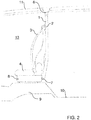
- FIG. 1 shows a front view of a support 1 according to an embodiment of the invention in an interior 13 of a motor vehicle while FIG. 2 an associated side view shows.
- FIGS. 1 and 2 With reference to the FIGS. 1 and 2 the interior 13 is replaced by a floor structure 10, a roof structure 11 and two in FIG. 1 limited only schematically and in principle indicated side structures 12.
- a motor vehicle seat 4 In the interior 13, a motor vehicle seat 4 is arranged.
- the support 1 comprises a suitably upper safety belt mounting device 2 for mounting a safety belt 3 for securing a person sitting on the motor vehicle seat 4 and is additionally expediently designed such that it has a roof deformation, in particular roof intrusion in the event of a crash (eg rollover). of the motor vehicle prevented or at least reduced to ensure a survival space in Immenraum 13.
- the seat belt 3 is part of a 3-point tether system.
- the support 1 extends appropriate sections laterally beside and behind the motor vehicle seat 4, in particular behind the seat back of the motor vehicle seat 4, and z. B. be designed as a round steel support.
- the motor vehicle seat 4 comprises a seat base 8, which is placed on a preferably platform-shaped bottom elevation 9 of the floor structure 10 and attached thereto z. B. is detachably mounted.
- the motor vehicle seat 4 is preferably a central and / or freestanding seat.
- the seat surface of the motor vehicle seat 4 expediently extends at a higher level than the seat surface of a laterally adjacent motor vehicle seat, a driver's seat and / or a passenger seat of the motor vehicle (see eg FIG. 4 ).
- the support 1 is mounted to an upper motor vehicle component, namely the roof structure 11, via an upper attachment means (eg, a substantially rigid threaded connection) 6 and a lower attachment means (eg, a substantially rigid one) Screw) 7 on a lower motor vehicle component, namely the seat base 8, mounted.
- an upper attachment means eg, a substantially rigid threaded connection
- a lower attachment means eg, a substantially rigid one
- Screw e.g, a substantially rigid one
- embodiments are also possible in the context of the invention, in which the lower fastening device 7 to the soil structure 10, z. B. the bottom elevation 9, is mounted. Also montages are at z. B. elements of upper and / or lower frame structures possible.
- FIG. 3 shows a cross-sectional view of a device 5 for compensation of emerging in the driving condition of the motor vehicle deformations, eg. B. torsions between the floor structure 10 and the roof structure 11, by means of which the z.
- FIGS. 1 and 2 shown support 1 can be equipped.
- the device 5 is preferably part of the upper fastening device 6 and provides for the support 1 a degree of freedom of movement in the longitudinal direction of the support 1.
- the device 5 comprises in particular a guide bush in which the support 1 is mounted longitudinally displaceable.
- the device 5 may preferably comprise a noise-inhibiting plastic element, preferably arranged between the guide bush and the support 1 and z. B. executed as a plastic sheath for the support. 1
- FIG. 3 it can also be seen that, for visual reasons, the device 5 can be provided with a cladding.
- FIG. 4 shows a perspective view of an interior 13 of a truck double cabin with a front seat row with three seats and with a support 1 according to an embodiment of the invention.
- FIG. 4 shows, in particular, that the motor vehicle seat 4 positioned in the foremost seat row can be arranged on a floor elevation 9 via a seat base 8, so that the seat surface of the motor vehicle seat 4 extends at a higher level than the seat surface of two laterally adjacent motor vehicle seats, in FIG. 4 of the driver's seat and the passenger's seat.
- FIG. 4 shows the seat belt 3 as two-tongue variant with expediently two locks.
Landscapes
- Engineering & Computer Science (AREA)
- Mechanical Engineering (AREA)
- Body Structure For Vehicles (AREA)
- Automotive Seat Belt Assembly (AREA)
Abstract
Description
- Die Erfindung betrifft eine Stütze mit zumindest einer Sicherheitsgurt-Montagevorrichtung zur Montage eines Sicherheitsgurts zum Sichern einer auf einem Kraftfahrzeug-Sitz sitzenden Person, wobei die Stütze zweckmäßig zur Anordnung in einem Innenraum eines Kraftfahrzeugs (z. B. Nutzfahrzeug oder Wohnmobil) vorgesehen ist und vorzugsweise zur Absicherung des Überlebensraums im Crash-Fall ausgelegt ist.
- Hohe Sicherheitsanforderungen in modernen Kraftfahrzeugen bedingen, fallweise auch durch Gesetzesvorgaben gestützt, eine weitestgehende Ausrüstung aller Sitze mit 3-Punkt-Sicherheitsgurten, sowie eine Verbesserung der Fahrgastzellenstabilität im Crashfall- z.B. ECE-R29/3 für LKW-Fahrerhäuser. Derzeit werden solche freistehenden Sitze sehr oft nur mit Beckengurten ausgerüstet.
- Eine aus der Praxis bekannte Lösung für die Ausrüstung eines freistehenden Sitzes mit einem 3-Punkt-Sicherheitsgurt ist die Verwendung eines sitzintegrierten Gurtes. Diese Lösung erfordert meist aufwändige kosten- und gewichtsintensive Verstärkungen in der Sitzstruktur und in der karosserieseitigen Anbindungsbasis für den Sitz. Da solche Sitze - z.B. Mittelsitz in einer verlängerten Kabinenvariante - meist ohne Schwingsystem ausgeführt sind, ist aus Fahrkomfortgründen ein sitzintegriertes Gurtsystem nicht erforderlich. Die in vielen Fällen exponierte Position eines solchen Sitzes - in der Mitte eines Fahrerhauses und eventuell auch gegenüber Fahrer- und Beifahrersitz erhöht - erfordert dann auch eine zusätzliche Verstärkung der Dachstruktur, um bei einem Unfall, z.B. Überschlag, den Passagier besser gegen die Deformation der Fahrgastzellenstruktur zu schützen, wobei diese Verstärkungsmaßnahmen, aufgrund der durch die räumliche Anordnung bedingten ungünstigen Kraftverläufe, entsprechend massiv ausgeführt werden müssen. In vielen Fällen erfolgt die Ausrüstung des betreffenden Fahrzeuges nicht generell mit Mittelsitzen, sondern nur auf Kundenwunsch, sodass die Verstärkungsmaßnahmen in der Dachstruktur und an der Sitzanbindungsbasis entweder die Herstellkosten der gesamten Baureihe erhöhen oder in der Produktion eine aufwändige Varianz erzeugen.
- Vor allem bei PKW-Anwendungen - vorzugsweise sogenannten SUV - sind auch Konzepte aus der Praxis bekannt, bei denen für den hinteren Mittelsitz der Gurtretraktor im Dach positioniert ist. Der Sicherheitsgurt (Gurtband) hat in diesem Fall zwei Zungen, die beim Anlegen des Sicherheitsgurtes in zwei Schlösser links und rechts vom Becken eingerastet werden. Dieses Konzept ist für freistehende Sitze im Nutzfahrzeugbereich nur bedingt tauglich, da aufgrund der im Vergleich zur Sitzposition meist höheren Dachinnenkontur der Sicherheitsgurt für den Nutzer wesentlich schwerer zu erreichen wäre. Auch bei diesem Konzept ist für den Crashfall eine zusätzliche Verstärkung im Dach erforderlich, was für kundenspezifische Anwendungsfälle die Produktvarianz erhöht bzw. das Grundfahrzeug verteuert.
- Eine Aufgabe der Erfindung ist es, ein alternatives und/oder verbessertes Sicherheitskonzept für einen Kraftfahrzeug-Innenraum zu schaffen.
- Diese Aufgabe kann mit den Merkmalen der unabhängigen Ansprüche gelöst werden. Vorteilhafte Weiterbildungen der Erfindung können den Unteransprüchen und der folgenden Beschreibung bevorzugter Ausführungsformen der Erfindung entnommen werden.
- Die Erfindung betrifft ein Kraftfahrzeug, z. B. ein Nutzfahrzeug, insbesondere einen Lastkraftwagen, oder ein Wohnmobil, mit einem Innenraum, der zweckmäßig durch eine Bodenstruktur, eine Dachstruktur und zwei Seitenstrukturen begrenzt ist. Zusätzlich kann der Innenraum noch z. B. eine Vorderwand und eine Rückwand aufweisen.
- Im Innenraum ist eine Stütze angeordnet, vorzugsweise eine freistehende, insbesondere vertikale oder im Wesentlichen vertikale Stütze und/oder eine beabstandet zwischen den zwei Seitenstrukturen positionierte Stütze.
- Die Stütze zeichnet sich insbesondere dadurch aus, dass sie zumindest eine Sicherheitsgurt-Montagevorrichtung zur Montage eines Sicherheitsgurts zum Sichern, insbesondere Rückhalten, einer auf einem Kraftfahrzeug-Sitz sitzenden Person aufweist.
- Die Stütze zeichnet sich vorzugsweise zusätzlich dadurch aus, dass sie zur Verhinderung oder zumindest Reduzierung einer Dachdeformation (z. B. Dachintrusion) im Crashfall des Kraftfahrzeugs ausgelegt ist, um im Crashfall einen Überlebensraum im Innenraum zu gewährleisten.
- Damit kann einer oder mehrere der folgenden Vorteile erzielt werden: Ausstattung von insbesondere freistehenden Sitzen in Kraftfahrzeugen mit ergonomisch optimal angeordneten und gut erreichbaren, fahrerhausfesten 3-Punkt-Haltegurt-Systemen; und/oder die Stütze eignet sich für alle üblichen Gurtkonzepte; und/oder weitgehende und gesetzeskonforme Absicherung des Überlebensraums (für die betreffende Person) im Crashfall des Kraftfahrzeugs; und/oder Adaption der Sicherheitsgurt-Anbindungsmaßnahmen und der entsprechenden Absicherung des Überlebensraums anwendungsbezogen und ohne wesentliche Kostenbelastung einer gesamte Baureihe im Fall kundenspezifischer Anwendungsfälle.
- Es ist möglich, dass die Stütze nur eine obere Sicherheitsgurt-Montagevorrichtung aufweist oder aber die Stütze eine obere Sicherheitsgurt-Montagevorrichtung und eine untere Sicherheitsgurt-Montagevorrichtung aufweist.
- Der Sicherheitsgurt kann z. B. als Teil eines 3-Punkt-Haltegurt-Systems ausgeführt sein, so dass zweckmäßig die Stütze also mit einem sogenannten 3-Punkt-Haltegurt-System ausgestattet sein kann. Hierbei ist z. B. auch eine sogenannte Zwei-Zungen-Variante mit zwei separaten Schlössern möglich.
- Es ist möglich, dass die Stütze mit zumindest einer Einrichtung zur Kompensation von im Fahrzustand des Kraftfahrzeugs entstehenden Verformungen versehen ist. Die Verformungen können z. B. Verwindungen, Verdrehungen und/oder andere Deformationen umfassen, zweckmäßig zwischen der Bodenstruktur und der Dachstruktur.
- Die Einrichtung kann z. B. zumindest einen Bewegungsfreiheitsgrad für die Stütze im Wesentlichen in Längsrichtung der Stütze zur Verfügung stellen. Alternativ oder ergänzend kann die Einrichtung z. B. eine Führungsbuchse umfassen, in der die Stütze zweckmäßig abschnittsweise längsverschieblich gelagert sein kann.
- Die Stütze kann z. B. über eine obere Befestigungseinrichtung an einem oberen Kraftfahrzeug-Bauteil (z. B. die Dachstruktur) montiert sein und/oder über eine untere Befestigungseinrichtung an einem unteren Kraftfahrzeug- Bauteil (z. B. die Bodenstruktur oder ein Sitzsockel) montiert sein.
- Es ist möglich, dass die Einrichtung Teil der oberen Befestigungseinrichtung und/oder Teil der unteren Befestigungseinrichtung ist. Es sind im Rahmen der Erfindung sogar Ausführungsformen möglich, in denen die Einrichtung zwischen der oberen Befestigungseinrichtung und der unteren Befestigungseinrichtung vorgesehen ist.
- Es ist möglich, dass die Einrichtung ein geräuschhemmendes Element umfasst, vorzugsweise angeordnet zwischen der Führungsbuchse und der Stütze, ausgeführt als Ummantelung für die Stütze und/oder hergestellt aus Kunststoff. Die Führungsbuchse kann zweckmäßig an der Dachstruktur fixiert sein.
- Es ist möglich, dass das obere Kraftfahrzeug-Bauteil die Dachstruktur umfasst und die obere Befestigungseinrichtung an die Dachstruktur montiert ist, z. B. im Wesentlichen starr.
- Es ist ebenfalls möglich, dass das untere Kraftfahrzeug-Bauteil einen vorzugsweise auf die Bodenstruktur aufsetzbaren und/oder daran z. B. lösbar anmontierbaren Sitzsockel umfasst und die untere Befestigungseinrichtung an den Sitzsockel montiert ist. Alternativ oder ergänzend kann das untere Kraftfahrzeug-Bauteil allerdings auch die Bodenstruktur umfassen und die untere Befestigungseinrichtung kann an die Bodenstruktur (z. B. eine Bodenerhöhung) montiert sein, z. B. im Wesentlichen starr.
- Der Kraftfahrzeug-Sitz kann ein mittlerer und/oder freistehender Sitz sein, wobei alternativ oder ergänzend die Stütze seitlich neben und/oder hinter der Sitzlehne des Kraftfahrzeug-Sitzes angeordnet sein kann.
- Es ist möglich, dass der Kraftfahrzeug-Sitz z. B. auf einer zweckmäßig podestförmigen Bodenerhöhung angeordnet ist und/oder die Sitzfläche des Kraftfahrzeug-Sitzes sich auf einem höheren Niveau erstreckt als die Sitzfläche zumindest eines seitlich benachbarten Kraftfahrzeugsitzes, eines Fahrersitzes und/oder eines Beifahrersitzes des Kraftfahrzeugs.
- Der Kraftfahrzeug-Sitz kann, wie schon zuvor erwähnt, ein mittlerer oder freistehender Sitz sein, wobei damit insbesondere ein Sitz in einer Sitzreihe zwischen zwei äußeren Sitzen umfasst ist (z. B. zwischen einem äußersten linken Sitz und einem äußersten rechten Sitz der Sitzreihe).
- Der Kraftfahrzeug-Sitz kann z. B. ein starrer oder einstellbarer Sitz sein.
- Der Kraftfahrzeug-Sitz ist vorzugsweise ohne Schwingenfunktion ausgeführt.
- Die Stütze kann im Wesentlichen über ihre gesamte Längserstreckung im Wesentlichen linear ausgeführt sein. Alternativ kann die Längserstreckung der Stütze einen oder mehrere Richtungswechsel aufweisen.
- Die Stütze kann in unterschiedlichen Querschnitten ausgeführt sein. Es können verschiedene zweckdienliche Materialien zum Einsatz kommen.
- Die obere Befestigungseinrichtung und/oder die untere Befestigungseinrichtung kann z. B. als Schraubverbindung ausgeführt sein und zum Toleranzausgleich z. B. ein Langloch umfassen.
- Es ist möglich, die Stütze als Träger für diverse Zusatzausrüstungen und/oder - anwendungen zu nutzen.
- Das obere Kraftfahrzeug-Bauteil und/oder die Dachstruktur können z. B. ein Dachpaneel oder eine Dachplatte (z. B. Dachinnenblech) umfassen, aber auch z. B. ein Element einer rahmenförmigen Tragstruktur.
- Das untere Kraftfahrzeug-Bauteil und/oder die Bodenstruktur können z. B. ein Bodenpaneel oder eine Bodenplatte (z. B. Bodeninnenblech) umfassen, aber auch z. B. ein Element einer rahmenförmigen Tragstruktur.
- Es ist möglich, dass die Sicherheitsgurt-Montagevorrichtung, insbesondere die obere Sicherheitsgurt-Montagevorrichtung so ausgeführt ist, um an der Stütze längsverschieblich montierbar zu sein. Dadurch kann zweckmäßig der Verlauf des Sicherheitsgurts an z. B. unterschiedlich große Personen angepasst werden.
- Der Innenraum kann vorzugsweise Teil eines Kraftfahrzeugs mit einer vordersten Sitzreihe mit zumindest drei Sitzplätzen sein, insbesondere Teil einer Doppelkabine.
- Der Kraftfahrzeug-Sitz kann vorzugsweise in der vordersten Sitzreihe des Kraftfahrzeugs, die zumindest zwei oder zumindest drei Sitze umfassen kann, positioniert sein.
- Die Erfindung ist nicht auf ein Kraftfahrzeug beschränkt, sondern umfasst ebenfalls eine Stütze wie hierin offenbart zur Anordnung in einem Innenraum eines Kraftfahrzeugs.
- Die zuvor beschriebenen Ausführungsformen und Merkmale der Erfindung sind miteinander kombinierbar. Andere vorteilhafte Weiterbildungen der Erfindung sind in den Unteransprüchen offenbart oder ergeben sich aus der folgenden Beschreibung bevorzugter Ausführungsformen der Erfindung in Verbindung mit den beigefügten Figuren.
- Figur 1
- zeigt eine Frontansicht einer Stütze gemäß einer Ausführungsform der Erfindung in einem Innenraum eines Kraftfahrzeugs,
- Figur 2
- zeigt eine Seitenansicht der in
Figur 1 gezeigten Ausführungsform, - Figur 3
- zeigt eine Schnittansicht einer Einrichtung zur Kompensation von im Fahrzustand des Kraftfahrzeugs entstehenden Verformungen für die z. B. in den
Figuren 1 und gezeigte Stütze, und - Figur 4
- zeigt eine perspektivische Ansicht mit Weglassungen zu Darstellungszwecken einer Stütze gemäß einer Ausführungsform der Erfindung in einem Innenraum eines Kraftfahrzeugs.
- Die unter Bezugnahme auf die Figuren beschriebenen Ausführungsformen stimmen teilweise überein, sodass ähnliche oder identische Teile mit den gleichen Bezugszeichen versehen sind und zu deren Erläuterung auch auf die Beschreibung der anderen Ausführungsformen verwiesen wird, um Wiederholungen zu vermeiden.
-
Figur 1 zeigt eine Frontansicht einer Stütze 1 gemäß einer Ausführungsform der Erfindung in einem Innenraum 13 eines Kraftfahrzeugs, währendFigur 2 eine zugehörige Seitenansicht zeigt. - Unter Bezugnahme auf die
Figuren 1 und2 wird der Innenraum 13 durch eine Bodenstruktur 10, eine Dachstruktur 11 und zwei inFigur 1 nur schematisch und prinzipiell angedeutete Seitenstrukturen 12 begrenzt. Im Innenraum 13 ist ein Kraftfahrzeug-Sitz 4 angeordnet. - Die Stütze 1 umfasst eine zweckmäßig obere Sicherheitsgurt-Montagevorrichtung 2 zur Montage eines Sicherheitsgurts 3 zum Sichern einer auf dem Kraftfahrzeug-Sitz 4 sitzenden Person und ist zusätzlich zweckmäßig so ausgelegt, dass sie eine Dachdeformation, insbesondere Dachintrusion im Crashfall (z. B. Überschlag) des Kraftfahrzeugs verhindert oder zumindest reduziert, um einen Überlebensraum im Immenraum 13 zu gewährleisten. Der Sicherheitsgurt 3 ist Teil eines 3-Punkt-Haltegurt-Systems. Die Stütze 1 erstreckt sich zweckmäßig abschnittsweise seitlich neben und hinter dem Kraftfahrzeug-Sitz 4, insbesondere hinter der Sitzlehne des Kraftfahrzeug-Sitzes 4, und kann z. B. als Rundrohr-Stahlstütze ausgeführt sein.
- Der Kraftfahrzeug-Sitz 4 umfasst einen Sitzsockel 8, der auf einer vorzugsweise podestförmigen Bodenerhöhung 9 der Bodenstruktur 10 aufgesetzt und daran z. B. lösbar anmontiert ist. Der Kraftfahrzeug-Sitz 4 ist vorzugsweise ein mittlerer und/oder freistehender Sitz. Die Sitzfläche des Kraftfahrzeug-Sitzes 4 erstreckt sich zweckmäßig auf einem höheren Niveau als die Sitzfläche eines seitlich benachbarten Kraftfahrzeug-Sitzes, eines Fahrersitzes und/oder eines Beifahrersitzes des Kraftfahrzeugs (siehe z. B.
Figur 4 ). - Die Stütze 1 ist über eine obere Befestigungseinrichtung (z. B. eine im Wesentlichen starre Schraubverbindung) 6 an ein oberes Kraftfahrzeug-Bauteil, nämlich die Dachstruktur 11, montiert und über eine untere Befestigungseinrichtung (z. B. eine im Wesentlichen starre Schraubverbindung) 7 an einem unteren Kraftfahrzeug-Bauteil, nämlich den Sitzsockel 8, montiert. Es sind im Rahmen der Erfindung allerdings auch Ausführungsformen möglich, bei denen die untere Befestigungseinrichtung 7 an die Bodenstruktur 10, z. B. die Bodenerhöhung 9, montiert ist. Ebenfalls sind Montagen an z. B. Elemente von oberen und/oder unteren Rahmenkonstruktionen möglich.
-
Figur 3 zeigt eine Querschnittsansicht einer Einrichtung 5 zur Kompensation von im Fahrzustand des Kraftfahrzeugs entstehender Verformungen, z. B. Verwindungen zwischen der Bodenstruktur 10 und der Dachstruktur 11, mittels der die z. B. in denFiguren 1 und2 gezeigte Stütze 1 ausgestattet werden kann. - Die Einrichtung 5 ist vorzugsweise Teil der oberen Befestigungseinrichtung 6 und stellt für die Stütze 1 einen Bewegungsfreiheitsgrad in Längsrichtung der Stütze 1 zur Verfügung. Die Einrichtung 5 umfasst insbesondere eine Führungsbuchse, in der die Stütze 1 längsverschieblich gelagert ist. Die Einrichtung 5 kann vorzugsweise ein geräuschhemmendes Kunststoffelement umfassen, vorzugsweise angeordnet zwischen der Führungsbuchse und der Stütze 1 und z. B. ausgeführt als Kunststoffummantelung für die Stütze 1.
-
Figur 3 kann außerdem entnommen werden, dass aus optischen Gründen die Einrichtung 5 mit einer Verkleidung versehen werden kann. -
Figur 4 zeigt eine perspektivische Ansicht eines Innenraums 13 einer LKW-Doppelkabine mit einer vordersten Sitzreihe mit drei Sitzen und mit einer Stütze 1 gemäß einer Ausführungsform der Erfindung. -
Figur 4 zeigt insbesondere, dass der in der vordersten Sitzreihe positionierte Kraftahrzeug-Sitz 4 über einen Sitzsockel 8 auf einer Bodenerhöhung 9 anordbar ist, so dass sich die Sitzfläche des Kraftfahrzeug-Sitzes 4 auf einem höheren Niveau erstreckt als die Sitzfläche zweier seitlich benachbarter Kraftfahrzeug-Sitze, inFigur 4 des Fahrersitzes und des Beifahrersitzes. -
Figur 4 zeigt den Sicherheitsgurt 3 als Zwei-Zungen-Variante mit zweckmäßig zwei Schlössern. - Die Erfindung ist nicht auf die oben beschriebenen bevorzugten Ausführungsformen beschränkt. Vielmehr ist eine Vielzahl von Varianten und Abwandlungen möglich, die ebenfalls von dem Erfindungsgedanken Gebrauch machen und deshalb in den Schutzbereich fallen.
- Darüber hinaus beansprucht die Erfindung auch Schutz für den Gegenstand und die Merkmale der Unteransprüche unabhängig von den in Bezug genommenen Merkmale und Ansprüchen.
-
- 1
- Stütze
- 2
- Sicherheitsgurt-Montagevorrichtung zur Montage eines Sicherheitsgurts zum Sichern einer auf einem Kraftfahrzeug-Sitz sitzenden Person, insbesondere eines Kraftfahrzeug-Passagiers
- 3
- Sicherheitsgurt
- 4
- Kraftfahrzeug-Sitz
- 5
- Einrichtung zur Kompensation von im Fahrzustand des Kraftfahrzeugs entstehenden Verformungen
- 6
- Obere Befestigungseinrichtung zur Montage der Stütze an ein oberes Kraftfahrzeug-Bauteil
- 7
- Untere Befestigungseinrichtung zur Montage der Stütze an ein unteres Kraftfahrzeug-Bauteil
- 8
- Sitzsockel
- 9
- Bodenerhöhung, insbesondere podestförmige Bodenerhöhung
- 10
- Bodenstruktur
- 11
- Dachstruktur
- 12
- Zweckmäßig zwei gegenüberliegende Seitenstrukturen
- 13
- Innenraum
Claims (15)
- Kraftfahrzeug, mit einem durch eine Bodenstruktur (10), eine Dachstruktur (11) und zwei Seitenstrukturen (12) begrenzten Innenraum (13), wobei im Innenraum (13) eine Stütze (1), vorzugsweise eine freistehende Stütze (1), angeordnet ist, dadurch gekennzeichnet, dass die Stütze (1) zumindest eine Sicherheitsgurt-Montagevorrichtung (2) zur Montage eines Sicherheitsgurts (3) zum Sichern einer auf einem Kraftfahrzeug-Sitz (4) sitzenden Person aufweist und vorzugsweise zur zumindest Reduzierung einer Dachdeformation im Crashfall des Kraftfahrzeugs ausgelegt ist, um einen Überlebensraum im Immenraum (13) zu gewährleisten.
- Kraftfahrzeug nach Anspruch 1, dadurch gekennzeichnet, dass die Stütze (1) nur eine obere Sicherheitsgurt-Montagevorrichtung (2) aufweist oder die Stütze (1) eine obere Sicherheitsgurt-Montagevorrichtung (2) und eine untere Sicherheitsgurt-Montagevorrichtung aufweist.
- Kraftfahrzeug nach einem der vorhergehenden Ansprüche, dadurch gekennzeichnet, dass der Sicherheitsgurt (3) Teil eines 3-Punkt-Haltegurt-Systems ist.
- Kraftfahrzeug nach einem der vorhergehenden Ansprüche, dadurch gekennzeichnet, dass die Stütze (1) mit zumindest einer Einrichtung (5) zur Kompensation von im Fahrzustand des Kraftfahrzeugs entstehenden Verformungen versehen ist.
- Kraftfahrzeug nach Anspruch 4, dadurch gekennzeichnet, dass die Einrichtung (5) einen Bewegungsfreiheitsgrad für die Stütze (1) in Längsrichtung der Stütze (1) zur Verfügung stellt und/oder die Einrichtung (5) eine Führungsbuchse umfasst, in der die Stütze (1) längsverschieblich gelagert ist.
- Kraftfahrzeug nach einem der vorhergehenden Ansprüche, dadurch gekennzeichnet, dass die Stütze (1) über eine obere Befestigungseinrichtung (6) an einem oberen Kraftfahrzeug-Bauteil montiert ist und/oder über eine untere Befestigungseinrichtung (7) an einem unteren Kraftfahrzeug-Bauteil montiert ist.
- Kraftfahrzeug nach einem der Ansprüche 4 bis 6, dadurch gekennzeichnet, dass die Einrichtung (5) Teil der oberen Befestigungseinrichtung (6) und/oder Teil der unteren Befestigungseinrichtung (7) ist.
- Kraftfahrzeug nach einem der Ansprüche 4 bis 7, dadurch gekennzeichnet, dass die Einrichtung (5) ein geräuschhemmendes Element umfasst, vorzugsweise angeordnet zwischen Führungsbuchse und Stütze (1), ausgeführt als Ummantelung für die Stütze (1) und/oder hergestellt aus Kunststoff.
- Kraftfahrzeug nach einem der Ansprüche 6 bis 8, dadurch gekennzeichnet, dass das obere Kraftfahrzeug-Bauteil die Dachstruktur (11) umfasst und die obere Befestigungseinrichtung (6) an die Dachstruktur (11) montiert ist.
- Kraftfahrzeug nach einem der Ansprüche 6 bis 9, dadurch gekennzeichnet, dass das untere Kraftfahrzeug-Bauteil einen Sitzsockel (8) und/oder die Bodenstruktur (10) umfasst und die untere Befestigungseinrichtung (7) hieran montiert ist.
- Kraftfahrzeug nach Anspruch 10, dadurch gekennzeichnet, dass der Sitzsockel (8) auf die Bodenstruktur (10) aufsetzbar und/oder daran anmontierbar ist.
- Kraftfahrzeug nach einem der vorhergehenden Ansprüche, dadurch gekennzeichnet, dass der Kraftfahrzeug-Sitz (4) ein mittlerer und/oder freistehender Kraftfahrzeug-Sitz (4) ist und die Stütze (1) seitlich neben und/oder hinter der Sitzlehne des Kraftfahrzeug-Sitzes (4) angeordnet ist.
- Kraftfahrzeug nach einem der vorhergehenden Ansprüche, dadurch gekennzeichnet, dass der Kraftfahrzeug-Sitz (4) auf einer Bodenerhöhung (9) angeordnet ist und/oder sich die Sitzfläche des Kraftfahrzeug-Sitzes (4) auf einem höheren Niveau erstreckt als die Sitzfläche zumindest eines seitlich benachbarten Kraftfahrzeug-Sitzes, eines Fahrersitzes und/oder eines Beifahrersitzes des Kraftfahrzeugs.
- Kraftfahrzeug nach einem der vorhergehenden Ansprüche, dadurch gekennzeichnet, dass der Innenraum (13) Teil eines Kraftfahrzeugs mit einer vordersten Sitzreihe mit zumindest drei Sitzplätzen ist und/oder der Kraftfahrzeug-Sitz (4) in der vordersten Sitzreihe des Kraftfahrzeugs positioniert ist.
- Stütze (1) nach dem kennzeichnenden Teil eines der vorhergehenden Ansprüche zur Anordnung im Immenraum (13) eines Kraftfahrzeugs.
Applications Claiming Priority (1)
| Application Number | Priority Date | Filing Date | Title |
|---|---|---|---|
| DE102016009145.2A DE102016009145A1 (de) | 2016-07-28 | 2016-07-28 | Stütze mit zumindest einer Sicherheitsgurt-Montagevorrichtung |
Publications (2)
| Publication Number | Publication Date |
|---|---|
| EP3275739A1 true EP3275739A1 (de) | 2018-01-31 |
| EP3275739B1 EP3275739B1 (de) | 2020-01-15 |
Family
ID=59363014
Family Applications (1)
| Application Number | Title | Priority Date | Filing Date |
|---|---|---|---|
| EP17181629.1A Active EP3275739B1 (de) | 2016-07-28 | 2017-07-17 | Kraftfahrzeug mit einer stütze mit zumindest einer sicherheitsgurt-montagevorrichtung |
Country Status (3)
| Country | Link |
|---|---|
| EP (1) | EP3275739B1 (de) |
| BR (1) | BR102017016167B1 (de) |
| DE (1) | DE102016009145A1 (de) |
Cited By (3)
| Publication number | Priority date | Publication date | Assignee | Title |
|---|---|---|---|---|
| US10343645B2 (en) * | 2017-03-24 | 2019-07-09 | Honda Motor Co., Ltd. | Seatbelt shoulder anchor |
| CN111465534A (zh) * | 2017-12-11 | 2020-07-28 | 雷诺股份公司 | 用于机动车辆的隔板 |
| US11440500B2 (en) * | 2020-02-10 | 2022-09-13 | Toyota Jidosha Kabushiki Kaisha | Vehicle occupant restraint structure |
Citations (8)
| Publication number | Priority date | Publication date | Assignee | Title |
|---|---|---|---|---|
| US2740642A (en) * | 1955-05-26 | 1956-04-03 | Walter A Atwood | Automobile passenger crash protector |
| US2891804A (en) * | 1954-12-16 | 1959-06-23 | John S Frayne | Vehicle body rigidifying device and mounting for passenger harness |
| US3885810A (en) * | 1972-01-10 | 1975-05-27 | John J Chika | Seat supporting structure for fast moving vehicles |
| WO1984000132A1 (en) * | 1982-06-23 | 1984-01-19 | John J Chika | Vehicle occupant restraining device |
| DE3614307A1 (de) * | 1986-04-28 | 1987-10-29 | Fiener Josef | Fahrzeugkarosserie |
| JPH03246172A (ja) * | 1990-02-23 | 1991-11-01 | Hino Motors Ltd | 車両用キャブの補強機構 |
| EP0635405A1 (de) * | 1993-07-21 | 1995-01-25 | DETHLEFFS GmbH | Motorcaravan mit einer Befestigungsvorrichtung für Sicherheitsgurte |
| JPH11165659A (ja) * | 1997-11-30 | 1999-06-22 | Isuzu Motors Ltd | キャブにおけるシートベルト取付構造 |
Family Cites Families (4)
| Publication number | Priority date | Publication date | Assignee | Title |
|---|---|---|---|---|
| DE2157899C3 (de) * | 1971-11-23 | 1978-03-23 | Adam Opel Ag, 6090 Ruesselsheim | Insassenrückhaltesystem in Fahrzeugen, insbesondere in Kraftfahrzeugen |
| DE19629128A1 (de) * | 1996-07-19 | 1998-01-22 | Auwaerter Gottlob Gmbh & Co | Omnibus |
| DE10130631B4 (de) * | 2001-06-26 | 2010-10-28 | Sieghard Schneider | Befestigungsvorrichtung für einen Fahrzeugsitz in einem minengeschützten Kraftfahrzeug |
| US20090295208A1 (en) * | 2008-05-29 | 2009-12-03 | Plasan Sasa Ltd. | Vehicle, suspension system, suspended object, and method of use thereof |
-
2016
- 2016-07-28 DE DE102016009145.2A patent/DE102016009145A1/de not_active Withdrawn
-
2017
- 2017-07-17 EP EP17181629.1A patent/EP3275739B1/de active Active
- 2017-07-27 BR BR102017016167-6A patent/BR102017016167B1/pt active IP Right Grant
Patent Citations (8)
| Publication number | Priority date | Publication date | Assignee | Title |
|---|---|---|---|---|
| US2891804A (en) * | 1954-12-16 | 1959-06-23 | John S Frayne | Vehicle body rigidifying device and mounting for passenger harness |
| US2740642A (en) * | 1955-05-26 | 1956-04-03 | Walter A Atwood | Automobile passenger crash protector |
| US3885810A (en) * | 1972-01-10 | 1975-05-27 | John J Chika | Seat supporting structure for fast moving vehicles |
| WO1984000132A1 (en) * | 1982-06-23 | 1984-01-19 | John J Chika | Vehicle occupant restraining device |
| DE3614307A1 (de) * | 1986-04-28 | 1987-10-29 | Fiener Josef | Fahrzeugkarosserie |
| JPH03246172A (ja) * | 1990-02-23 | 1991-11-01 | Hino Motors Ltd | 車両用キャブの補強機構 |
| EP0635405A1 (de) * | 1993-07-21 | 1995-01-25 | DETHLEFFS GmbH | Motorcaravan mit einer Befestigungsvorrichtung für Sicherheitsgurte |
| JPH11165659A (ja) * | 1997-11-30 | 1999-06-22 | Isuzu Motors Ltd | キャブにおけるシートベルト取付構造 |
Cited By (3)
| Publication number | Priority date | Publication date | Assignee | Title |
|---|---|---|---|---|
| US10343645B2 (en) * | 2017-03-24 | 2019-07-09 | Honda Motor Co., Ltd. | Seatbelt shoulder anchor |
| CN111465534A (zh) * | 2017-12-11 | 2020-07-28 | 雷诺股份公司 | 用于机动车辆的隔板 |
| US11440500B2 (en) * | 2020-02-10 | 2022-09-13 | Toyota Jidosha Kabushiki Kaisha | Vehicle occupant restraint structure |
Also Published As
| Publication number | Publication date |
|---|---|
| BR102017016167A2 (pt) | 2018-05-02 |
| BR102017016167B1 (pt) | 2022-10-25 |
| EP3275739B1 (de) | 2020-01-15 |
| BR102017016167A8 (pt) | 2022-08-23 |
| DE102016009145A1 (de) | 2018-02-01 |
Similar Documents
| Publication | Publication Date | Title |
|---|---|---|
| EP3964405B1 (de) | Lasttragendes strukturteil für einen fahrzeugsitz | |
| EP0765252B1 (de) | Sitzbank für kraftfahrzeuge, insbesondere wohnmobile | |
| DE10219764B4 (de) | Klappbare Fahrzeugbordwand mit daran befestigten Sitzkomponenten | |
| EP3519244B1 (de) | Sitzanlage für einen kraftwagen | |
| DE2166310C3 (de) | Überrollschutzanordnung für Fahrzeuge, insbesondere Kraftfahrzeuge | |
| EP3429887B1 (de) | Fahrzeug mit einer mittelsitzposition | |
| DE102018218293A1 (de) | Gurtaufroller | |
| DE102010018638A1 (de) | Trägerstruktur eines Sitzquerträgers | |
| EP3275739B1 (de) | Kraftfahrzeug mit einer stütze mit zumindest einer sicherheitsgurt-montagevorrichtung | |
| DE10130631B4 (de) | Befestigungsvorrichtung für einen Fahrzeugsitz in einem minengeschützten Kraftfahrzeug | |
| DE10351179B4 (de) | Sicherheitshaltevorrichtung für einen Insassen eines Fahrzeuges | |
| DE102011010705A1 (de) | Personenkraftfahrzeug ohne B-Säule | |
| EP1477360A2 (de) | Rückenlehne | |
| DE202021104178U1 (de) | Baugruppe zur Befestigung eines Fahrzeugsitzes an einem Fahrzeugboden einer gepanzerten Fahrgastzelle | |
| EP4223596B1 (de) | Gurtgestell für einen fahrzeugsitz | |
| DE102011112307A1 (de) | Personenkraftwagen mit einem Verkleidungsteil für Sitzbefestigungsmittel | |
| EP1386830B1 (de) | Bodyintegrierter Sitzhalter | |
| DE102012112077A1 (de) | Querträger mit Schutzvorrichtung | |
| DE102007030255A1 (de) | Fahrerkabine eines Fahrzeugs | |
| DE19939548B4 (de) | Kraftfahrzeug nach Art eines Pritschenwagens mit Sicherheitsgurtbefestigung an einer Kabinenrückwand | |
| DE102024131483A1 (de) | Kraftfahrzeug | |
| DE102010045144A1 (de) | Karosserie für einen Kraftwagen | |
| EP4194262A1 (de) | Freizeitfahrzeug mit einer verstellbaren sitzeinrichtung | |
| DE102005001969A1 (de) | Vorrichtung zur Ermöglichung des Zugangs zu einem abgeschlossenen Raum innerhalb eines Kraftfahrzeugs | |
| DE10059788A1 (de) | Fahrzeugsitz |
Legal Events
| Date | Code | Title | Description |
|---|---|---|---|
| PUAI | Public reference made under article 153(3) epc to a published international application that has entered the european phase |
Free format text: ORIGINAL CODE: 0009012 |
|
| STAA | Information on the status of an ep patent application or granted ep patent |
Free format text: STATUS: THE APPLICATION HAS BEEN PUBLISHED |
|
| AK | Designated contracting states |
Kind code of ref document: A1 Designated state(s): AL AT BE BG CH CY CZ DE DK EE ES FI FR GB GR HR HU IE IS IT LI LT LU LV MC MK MT NL NO PL PT RO RS SE SI SK SM TR |
|
| AX | Request for extension of the european patent |
Extension state: BA ME |
|
| STAA | Information on the status of an ep patent application or granted ep patent |
Free format text: STATUS: REQUEST FOR EXAMINATION WAS MADE |
|
| 17P | Request for examination filed |
Effective date: 20180620 |
|
| RBV | Designated contracting states (corrected) |
Designated state(s): AL AT BE BG CH CY CZ DE DK EE ES FI FR GB GR HR HU IE IS IT LI LT LU LV MC MK MT NL NO PL PT RO RS SE SI SK SM TR |
|
| STAA | Information on the status of an ep patent application or granted ep patent |
Free format text: STATUS: EXAMINATION IS IN PROGRESS |
|
| 17Q | First examination report despatched |
Effective date: 20190226 |
|
| RAP1 | Party data changed (applicant data changed or rights of an application transferred) |
Owner name: MAN TRUCK & BUS SE |
|
| GRAP | Despatch of communication of intention to grant a patent |
Free format text: ORIGINAL CODE: EPIDOSNIGR1 |
|
| STAA | Information on the status of an ep patent application or granted ep patent |
Free format text: STATUS: GRANT OF PATENT IS INTENDED |
|
| INTG | Intention to grant announced |
Effective date: 20190826 |
|
| GRAS | Grant fee paid |
Free format text: ORIGINAL CODE: EPIDOSNIGR3 |
|
| GRAA | (expected) grant |
Free format text: ORIGINAL CODE: 0009210 |
|
| STAA | Information on the status of an ep patent application or granted ep patent |
Free format text: STATUS: THE PATENT HAS BEEN GRANTED |
|
| AK | Designated contracting states |
Kind code of ref document: B1 Designated state(s): AL AT BE BG CH CY CZ DE DK EE ES FI FR GB GR HR HU IE IS IT LI LT LU LV MC MK MT NL NO PL PT RO RS SE SI SK SM TR |
|
| REG | Reference to a national code |
Ref country code: CH Ref legal event code: EP Ref country code: GB Ref legal event code: FG4D Free format text: NOT ENGLISH |
|
| REG | Reference to a national code |
Ref country code: IE Ref legal event code: FG4D Free format text: LANGUAGE OF EP DOCUMENT: GERMAN |
|
| REG | Reference to a national code |
Ref country code: DE Ref legal event code: R096 Ref document number: 502017003497 Country of ref document: DE |
|
| REG | Reference to a national code |
Ref country code: AT Ref legal event code: REF Ref document number: 1224898 Country of ref document: AT Kind code of ref document: T Effective date: 20200215 |
|
| REG | Reference to a national code |
Ref country code: NL Ref legal event code: FP |
|
| REG | Reference to a national code |
Ref country code: SE Ref legal event code: TRGR |
|
| REG | Reference to a national code |
Ref country code: LT Ref legal event code: MG4D |
|
| PG25 | Lapsed in a contracting state [announced via postgrant information from national office to epo] |
Ref country code: NO Free format text: LAPSE BECAUSE OF FAILURE TO SUBMIT A TRANSLATION OF THE DESCRIPTION OR TO PAY THE FEE WITHIN THE PRESCRIBED TIME-LIMIT Effective date: 20200415 Ref country code: RS Free format text: LAPSE BECAUSE OF FAILURE TO SUBMIT A TRANSLATION OF THE DESCRIPTION OR TO PAY THE FEE WITHIN THE PRESCRIBED TIME-LIMIT Effective date: 20200115 Ref country code: FI Free format text: LAPSE BECAUSE OF FAILURE TO SUBMIT A TRANSLATION OF THE DESCRIPTION OR TO PAY THE FEE WITHIN THE PRESCRIBED TIME-LIMIT Effective date: 20200115 Ref country code: PT Free format text: LAPSE BECAUSE OF FAILURE TO SUBMIT A TRANSLATION OF THE DESCRIPTION OR TO PAY THE FEE WITHIN THE PRESCRIBED TIME-LIMIT Effective date: 20200607 |
|
| PG25 | Lapsed in a contracting state [announced via postgrant information from national office to epo] |
Ref country code: IS Free format text: LAPSE BECAUSE OF FAILURE TO SUBMIT A TRANSLATION OF THE DESCRIPTION OR TO PAY THE FEE WITHIN THE PRESCRIBED TIME-LIMIT Effective date: 20200515 Ref country code: GR Free format text: LAPSE BECAUSE OF FAILURE TO SUBMIT A TRANSLATION OF THE DESCRIPTION OR TO PAY THE FEE WITHIN THE PRESCRIBED TIME-LIMIT Effective date: 20200416 Ref country code: LV Free format text: LAPSE BECAUSE OF FAILURE TO SUBMIT A TRANSLATION OF THE DESCRIPTION OR TO PAY THE FEE WITHIN THE PRESCRIBED TIME-LIMIT Effective date: 20200115 Ref country code: HR Free format text: LAPSE BECAUSE OF FAILURE TO SUBMIT A TRANSLATION OF THE DESCRIPTION OR TO PAY THE FEE WITHIN THE PRESCRIBED TIME-LIMIT Effective date: 20200115 Ref country code: BG Free format text: LAPSE BECAUSE OF FAILURE TO SUBMIT A TRANSLATION OF THE DESCRIPTION OR TO PAY THE FEE WITHIN THE PRESCRIBED TIME-LIMIT Effective date: 20200415 |
|
| REG | Reference to a national code |
Ref country code: DE Ref legal event code: R097 Ref document number: 502017003497 Country of ref document: DE |
|
| PG25 | Lapsed in a contracting state [announced via postgrant information from national office to epo] |
Ref country code: DK Free format text: LAPSE BECAUSE OF FAILURE TO SUBMIT A TRANSLATION OF THE DESCRIPTION OR TO PAY THE FEE WITHIN THE PRESCRIBED TIME-LIMIT Effective date: 20200115 Ref country code: EE Free format text: LAPSE BECAUSE OF FAILURE TO SUBMIT A TRANSLATION OF THE DESCRIPTION OR TO PAY THE FEE WITHIN THE PRESCRIBED TIME-LIMIT Effective date: 20200115 Ref country code: ES Free format text: LAPSE BECAUSE OF FAILURE TO SUBMIT A TRANSLATION OF THE DESCRIPTION OR TO PAY THE FEE WITHIN THE PRESCRIBED TIME-LIMIT Effective date: 20200115 Ref country code: LT Free format text: LAPSE BECAUSE OF FAILURE TO SUBMIT A TRANSLATION OF THE DESCRIPTION OR TO PAY THE FEE WITHIN THE PRESCRIBED TIME-LIMIT Effective date: 20200115 Ref country code: CZ Free format text: LAPSE BECAUSE OF FAILURE TO SUBMIT A TRANSLATION OF THE DESCRIPTION OR TO PAY THE FEE WITHIN THE PRESCRIBED TIME-LIMIT Effective date: 20200115 Ref country code: RO Free format text: LAPSE BECAUSE OF FAILURE TO SUBMIT A TRANSLATION OF THE DESCRIPTION OR TO PAY THE FEE WITHIN THE PRESCRIBED TIME-LIMIT Effective date: 20200115 Ref country code: SK Free format text: LAPSE BECAUSE OF FAILURE TO SUBMIT A TRANSLATION OF THE DESCRIPTION OR TO PAY THE FEE WITHIN THE PRESCRIBED TIME-LIMIT Effective date: 20200115 Ref country code: SM Free format text: LAPSE BECAUSE OF FAILURE TO SUBMIT A TRANSLATION OF THE DESCRIPTION OR TO PAY THE FEE WITHIN THE PRESCRIBED TIME-LIMIT Effective date: 20200115 |
|
| PLBE | No opposition filed within time limit |
Free format text: ORIGINAL CODE: 0009261 |
|
| STAA | Information on the status of an ep patent application or granted ep patent |
Free format text: STATUS: NO OPPOSITION FILED WITHIN TIME LIMIT |
|
| 26N | No opposition filed |
Effective date: 20201016 |
|
| PG25 | Lapsed in a contracting state [announced via postgrant information from national office to epo] |
Ref country code: SI Free format text: LAPSE BECAUSE OF FAILURE TO SUBMIT A TRANSLATION OF THE DESCRIPTION OR TO PAY THE FEE WITHIN THE PRESCRIBED TIME-LIMIT Effective date: 20200115 Ref country code: MC Free format text: LAPSE BECAUSE OF FAILURE TO SUBMIT A TRANSLATION OF THE DESCRIPTION OR TO PAY THE FEE WITHIN THE PRESCRIBED TIME-LIMIT Effective date: 20200115 Ref country code: PL Free format text: LAPSE BECAUSE OF FAILURE TO SUBMIT A TRANSLATION OF THE DESCRIPTION OR TO PAY THE FEE WITHIN THE PRESCRIBED TIME-LIMIT Effective date: 20200115 |
|
| REG | Reference to a national code |
Ref country code: CH Ref legal event code: PL |
|
| REG | Reference to a national code |
Ref country code: BE Ref legal event code: MM Effective date: 20200731 |
|
| PG25 | Lapsed in a contracting state [announced via postgrant information from national office to epo] |
Ref country code: LU Free format text: LAPSE BECAUSE OF NON-PAYMENT OF DUE FEES Effective date: 20200717 Ref country code: LI Free format text: LAPSE BECAUSE OF NON-PAYMENT OF DUE FEES Effective date: 20200731 Ref country code: CH Free format text: LAPSE BECAUSE OF NON-PAYMENT OF DUE FEES Effective date: 20200731 |
|
| PG25 | Lapsed in a contracting state [announced via postgrant information from national office to epo] |
Ref country code: BE Free format text: LAPSE BECAUSE OF NON-PAYMENT OF DUE FEES Effective date: 20200731 |
|
| PG25 | Lapsed in a contracting state [announced via postgrant information from national office to epo] |
Ref country code: IE Free format text: LAPSE BECAUSE OF NON-PAYMENT OF DUE FEES Effective date: 20200717 |
|
| GBPC | Gb: european patent ceased through non-payment of renewal fee |
Effective date: 20210717 |
|
| PG25 | Lapsed in a contracting state [announced via postgrant information from national office to epo] |
Ref country code: GB Free format text: LAPSE BECAUSE OF NON-PAYMENT OF DUE FEES Effective date: 20210717 |
|
| PG25 | Lapsed in a contracting state [announced via postgrant information from national office to epo] |
Ref country code: MT Free format text: LAPSE BECAUSE OF FAILURE TO SUBMIT A TRANSLATION OF THE DESCRIPTION OR TO PAY THE FEE WITHIN THE PRESCRIBED TIME-LIMIT Effective date: 20200115 Ref country code: CY Free format text: LAPSE BECAUSE OF FAILURE TO SUBMIT A TRANSLATION OF THE DESCRIPTION OR TO PAY THE FEE WITHIN THE PRESCRIBED TIME-LIMIT Effective date: 20200115 |
|
| PG25 | Lapsed in a contracting state [announced via postgrant information from national office to epo] |
Ref country code: MK Free format text: LAPSE BECAUSE OF FAILURE TO SUBMIT A TRANSLATION OF THE DESCRIPTION OR TO PAY THE FEE WITHIN THE PRESCRIBED TIME-LIMIT Effective date: 20200115 Ref country code: AL Free format text: LAPSE BECAUSE OF FAILURE TO SUBMIT A TRANSLATION OF THE DESCRIPTION OR TO PAY THE FEE WITHIN THE PRESCRIBED TIME-LIMIT Effective date: 20200115 |
|
| REG | Reference to a national code |
Ref country code: AT Ref legal event code: MM01 Ref document number: 1224898 Country of ref document: AT Kind code of ref document: T Effective date: 20220717 |
|
| PG25 | Lapsed in a contracting state [announced via postgrant information from national office to epo] |
Ref country code: AT Free format text: LAPSE BECAUSE OF NON-PAYMENT OF DUE FEES Effective date: 20220717 |
|
| PGFP | Annual fee paid to national office [announced via postgrant information from national office to epo] |
Ref country code: NL Payment date: 20250724 Year of fee payment: 9 |
|
| PGFP | Annual fee paid to national office [announced via postgrant information from national office to epo] |
Ref country code: DE Payment date: 20250728 Year of fee payment: 9 |
|
| PGFP | Annual fee paid to national office [announced via postgrant information from national office to epo] |
Ref country code: IT Payment date: 20250721 Year of fee payment: 9 Ref country code: TR Payment date: 20250707 Year of fee payment: 9 |
|
| PGFP | Annual fee paid to national office [announced via postgrant information from national office to epo] |
Ref country code: FR Payment date: 20250725 Year of fee payment: 9 |
|
| PGFP | Annual fee paid to national office [announced via postgrant information from national office to epo] |
Ref country code: SE Payment date: 20250725 Year of fee payment: 9 |