EP3275482A1 - Syringe holder and medical solution administration set - Google Patents
Syringe holder and medical solution administration set Download PDFInfo
- Publication number
- EP3275482A1 EP3275482A1 EP16768861.3A EP16768861A EP3275482A1 EP 3275482 A1 EP3275482 A1 EP 3275482A1 EP 16768861 A EP16768861 A EP 16768861A EP 3275482 A1 EP3275482 A1 EP 3275482A1
- Authority
- EP
- European Patent Office
- Prior art keywords
- syringe
- barrel body
- holder
- opening
- flange
- Prior art date
- Legal status (The legal status is an assumption and is not a legal conclusion. Google has not performed a legal analysis and makes no representation as to the accuracy of the status listed.)
- Granted
Links
Images




Classifications
-
- A—HUMAN NECESSITIES
- A61—MEDICAL OR VETERINARY SCIENCE; HYGIENE
- A61M—DEVICES FOR INTRODUCING MEDIA INTO, OR ONTO, THE BODY; DEVICES FOR TRANSDUCING BODY MEDIA OR FOR TAKING MEDIA FROM THE BODY; DEVICES FOR PRODUCING OR ENDING SLEEP OR STUPOR
- A61M5/00—Devices for bringing media into the body in a subcutaneous, intra-vascular or intramuscular way; Accessories therefor, e.g. filling or cleaning devices, arm-rests
- A61M5/178—Syringes
- A61M5/31—Details
- A61M5/3129—Syringe barrels
- A61M5/3137—Specially designed finger grip means, e.g. for easy manipulation of the syringe rod
-
- A—HUMAN NECESSITIES
- A61—MEDICAL OR VETERINARY SCIENCE; HYGIENE
- A61M—DEVICES FOR INTRODUCING MEDIA INTO, OR ONTO, THE BODY; DEVICES FOR TRANSDUCING BODY MEDIA OR FOR TAKING MEDIA FROM THE BODY; DEVICES FOR PRODUCING OR ENDING SLEEP OR STUPOR
- A61M5/00—Devices for bringing media into the body in a subcutaneous, intra-vascular or intramuscular way; Accessories therefor, e.g. filling or cleaning devices, arm-rests
- A61M5/178—Syringes
- A61M5/24—Ampoule syringes, i.e. syringes with needle for use in combination with replaceable ampoules or carpules, e.g. automatic
-
- A—HUMAN NECESSITIES
- A61—MEDICAL OR VETERINARY SCIENCE; HYGIENE
- A61J—CONTAINERS SPECIALLY ADAPTED FOR MEDICAL OR PHARMACEUTICAL PURPOSES; DEVICES OR METHODS SPECIALLY ADAPTED FOR BRINGING PHARMACEUTICAL PRODUCTS INTO PARTICULAR PHYSICAL OR ADMINISTERING FORMS; DEVICES FOR ADMINISTERING FOOD OR MEDICINES ORALLY; BABY COMFORTERS; DEVICES FOR RECEIVING SPITTLE
- A61J1/00—Containers specially adapted for medical or pharmaceutical purposes
- A61J1/14—Details; Accessories therefor
- A61J1/16—Holders for containers
-
- A—HUMAN NECESSITIES
- A61—MEDICAL OR VETERINARY SCIENCE; HYGIENE
- A61M—DEVICES FOR INTRODUCING MEDIA INTO, OR ONTO, THE BODY; DEVICES FOR TRANSDUCING BODY MEDIA OR FOR TAKING MEDIA FROM THE BODY; DEVICES FOR PRODUCING OR ENDING SLEEP OR STUPOR
- A61M5/00—Devices for bringing media into the body in a subcutaneous, intra-vascular or intramuscular way; Accessories therefor, e.g. filling or cleaning devices, arm-rests
- A61M5/178—Syringes
- A61M5/28—Syringe ampoules or carpules, i.e. ampoules or carpules provided with a needle
-
- A—HUMAN NECESSITIES
- A61—MEDICAL OR VETERINARY SCIENCE; HYGIENE
- A61M—DEVICES FOR INTRODUCING MEDIA INTO, OR ONTO, THE BODY; DEVICES FOR TRANSDUCING BODY MEDIA OR FOR TAKING MEDIA FROM THE BODY; DEVICES FOR PRODUCING OR ENDING SLEEP OR STUPOR
- A61M5/00—Devices for bringing media into the body in a subcutaneous, intra-vascular or intramuscular way; Accessories therefor, e.g. filling or cleaning devices, arm-rests
- A61M5/178—Syringes
- A61M5/31—Details
-
- A—HUMAN NECESSITIES
- A61—MEDICAL OR VETERINARY SCIENCE; HYGIENE
- A61M—DEVICES FOR INTRODUCING MEDIA INTO, OR ONTO, THE BODY; DEVICES FOR TRANSDUCING BODY MEDIA OR FOR TAKING MEDIA FROM THE BODY; DEVICES FOR PRODUCING OR ENDING SLEEP OR STUPOR
- A61M5/00—Devices for bringing media into the body in a subcutaneous, intra-vascular or intramuscular way; Accessories therefor, e.g. filling or cleaning devices, arm-rests
- A61M5/178—Syringes
- A61M5/31—Details
- A61M5/32—Needles; Details of needles pertaining to their connection with syringe or hub; Accessories for bringing the needle into, or holding the needle on, the body; Devices for protection of needles
- A61M5/3205—Apparatus for removing or disposing of used needles or syringes, e.g. containers; Means for protection against accidental injuries from used needles
- A61M5/321—Means for protection against accidental injuries by used needles
- A61M5/3243—Means for protection against accidental injuries by used needles being axially-extensible, e.g. protective sleeves coaxially slidable on the syringe barrel
- A61M5/326—Fully automatic sleeve extension, i.e. in which triggering of the sleeve does not require a deliberate action by the user
-
- A—HUMAN NECESSITIES
- A61—MEDICAL OR VETERINARY SCIENCE; HYGIENE
- A61M—DEVICES FOR INTRODUCING MEDIA INTO, OR ONTO, THE BODY; DEVICES FOR TRANSDUCING BODY MEDIA OR FOR TAKING MEDIA FROM THE BODY; DEVICES FOR PRODUCING OR ENDING SLEEP OR STUPOR
- A61M5/00—Devices for bringing media into the body in a subcutaneous, intra-vascular or intramuscular way; Accessories therefor, e.g. filling or cleaning devices, arm-rests
- A61M5/178—Syringes
- A61M5/31—Details
- A61M5/32—Needles; Details of needles pertaining to their connection with syringe or hub; Accessories for bringing the needle into, or holding the needle on, the body; Devices for protection of needles
- A61M5/34—Constructions for connecting the needle, e.g. to syringe nozzle or needle hub
- A61M5/344—Constructions for connecting the needle, e.g. to syringe nozzle or needle hub using additional parts, e.g. clamping rings or collets
-
- A—HUMAN NECESSITIES
- A61—MEDICAL OR VETERINARY SCIENCE; HYGIENE
- A61M—DEVICES FOR INTRODUCING MEDIA INTO, OR ONTO, THE BODY; DEVICES FOR TRANSDUCING BODY MEDIA OR FOR TAKING MEDIA FROM THE BODY; DEVICES FOR PRODUCING OR ENDING SLEEP OR STUPOR
- A61M5/00—Devices for bringing media into the body in a subcutaneous, intra-vascular or intramuscular way; Accessories therefor, e.g. filling or cleaning devices, arm-rests
- A61M5/178—Syringes
- A61M5/24—Ampoule syringes, i.e. syringes with needle for use in combination with replaceable ampoules or carpules, e.g. automatic
- A61M2005/2485—Ampoule holder connected to rest of syringe
- A61M2005/2488—Ampoule holder connected to rest of syringe via rotation, e.g. threads or bayonet
-
- A—HUMAN NECESSITIES
- A61—MEDICAL OR VETERINARY SCIENCE; HYGIENE
- A61M—DEVICES FOR INTRODUCING MEDIA INTO, OR ONTO, THE BODY; DEVICES FOR TRANSDUCING BODY MEDIA OR FOR TAKING MEDIA FROM THE BODY; DEVICES FOR PRODUCING OR ENDING SLEEP OR STUPOR
- A61M5/00—Devices for bringing media into the body in a subcutaneous, intra-vascular or intramuscular way; Accessories therefor, e.g. filling or cleaning devices, arm-rests
- A61M5/178—Syringes
- A61M5/31—Details
- A61M2005/3103—Leak prevention means for distal end of syringes, i.e. syringe end for mounting a needle
- A61M2005/3104—Caps for syringes without needle
-
- A—HUMAN NECESSITIES
- A61—MEDICAL OR VETERINARY SCIENCE; HYGIENE
- A61M—DEVICES FOR INTRODUCING MEDIA INTO, OR ONTO, THE BODY; DEVICES FOR TRANSDUCING BODY MEDIA OR FOR TAKING MEDIA FROM THE BODY; DEVICES FOR PRODUCING OR ENDING SLEEP OR STUPOR
- A61M5/00—Devices for bringing media into the body in a subcutaneous, intra-vascular or intramuscular way; Accessories therefor, e.g. filling or cleaning devices, arm-rests
- A61M5/178—Syringes
- A61M5/31—Details
- A61M5/3129—Syringe barrels
- A61M5/3137—Specially designed finger grip means, e.g. for easy manipulation of the syringe rod
- A61M2005/3139—Finger grips not integrally formed with the syringe barrel, e.g. using adapter with finger grips
-
- A—HUMAN NECESSITIES
- A61—MEDICAL OR VETERINARY SCIENCE; HYGIENE
- A61M—DEVICES FOR INTRODUCING MEDIA INTO, OR ONTO, THE BODY; DEVICES FOR TRANSDUCING BODY MEDIA OR FOR TAKING MEDIA FROM THE BODY; DEVICES FOR PRODUCING OR ENDING SLEEP OR STUPOR
- A61M5/00—Devices for bringing media into the body in a subcutaneous, intra-vascular or intramuscular way; Accessories therefor, e.g. filling or cleaning devices, arm-rests
- A61M5/178—Syringes
- A61M5/31—Details
- A61M5/32—Needles; Details of needles pertaining to their connection with syringe or hub; Accessories for bringing the needle into, or holding the needle on, the body; Devices for protection of needles
- A61M5/3205—Apparatus for removing or disposing of used needles or syringes, e.g. containers; Means for protection against accidental injuries from used needles
- A61M5/321—Means for protection against accidental injuries by used needles
- A61M5/3243—Means for protection against accidental injuries by used needles being axially-extensible, e.g. protective sleeves coaxially slidable on the syringe barrel
- A61M5/3245—Constructional features thereof, e.g. to improve manipulation or functioning
- A61M2005/3247—Means to impede repositioning of protection sleeve from needle covering to needle uncovering position
-
- A—HUMAN NECESSITIES
- A61—MEDICAL OR VETERINARY SCIENCE; HYGIENE
- A61M—DEVICES FOR INTRODUCING MEDIA INTO, OR ONTO, THE BODY; DEVICES FOR TRANSDUCING BODY MEDIA OR FOR TAKING MEDIA FROM THE BODY; DEVICES FOR PRODUCING OR ENDING SLEEP OR STUPOR
- A61M5/00—Devices for bringing media into the body in a subcutaneous, intra-vascular or intramuscular way; Accessories therefor, e.g. filling or cleaning devices, arm-rests
- A61M5/178—Syringes
- A61M5/31—Details
- A61M5/32—Needles; Details of needles pertaining to their connection with syringe or hub; Accessories for bringing the needle into, or holding the needle on, the body; Devices for protection of needles
- A61M5/3205—Apparatus for removing or disposing of used needles or syringes, e.g. containers; Means for protection against accidental injuries from used needles
- A61M5/321—Means for protection against accidental injuries by used needles
- A61M5/3243—Means for protection against accidental injuries by used needles being axially-extensible, e.g. protective sleeves coaxially slidable on the syringe barrel
- A61M5/326—Fully automatic sleeve extension, i.e. in which triggering of the sleeve does not require a deliberate action by the user
- A61M2005/3261—Fully automatic sleeve extension, i.e. in which triggering of the sleeve does not require a deliberate action by the user triggered by radial deflection of the anchoring parts between sleeve and syringe barrel, e.g. spreading of sleeve retaining hooks having slanted surfaces by engagement with conically shaped collet of the piston rod during the last portion of the injection stroke of the plunger
-
- A—HUMAN NECESSITIES
- A61—MEDICAL OR VETERINARY SCIENCE; HYGIENE
- A61M—DEVICES FOR INTRODUCING MEDIA INTO, OR ONTO, THE BODY; DEVICES FOR TRANSDUCING BODY MEDIA OR FOR TAKING MEDIA FROM THE BODY; DEVICES FOR PRODUCING OR ENDING SLEEP OR STUPOR
- A61M5/00—Devices for bringing media into the body in a subcutaneous, intra-vascular or intramuscular way; Accessories therefor, e.g. filling or cleaning devices, arm-rests
- A61M5/178—Syringes
- A61M5/31—Details
- A61M5/32—Needles; Details of needles pertaining to their connection with syringe or hub; Accessories for bringing the needle into, or holding the needle on, the body; Devices for protection of needles
- A61M5/3205—Apparatus for removing or disposing of used needles or syringes, e.g. containers; Means for protection against accidental injuries from used needles
- A61M5/321—Means for protection against accidental injuries by used needles
- A61M5/3243—Means for protection against accidental injuries by used needles being axially-extensible, e.g. protective sleeves coaxially slidable on the syringe barrel
- A61M5/326—Fully automatic sleeve extension, i.e. in which triggering of the sleeve does not require a deliberate action by the user
- A61M2005/3261—Fully automatic sleeve extension, i.e. in which triggering of the sleeve does not require a deliberate action by the user triggered by radial deflection of the anchoring parts between sleeve and syringe barrel, e.g. spreading of sleeve retaining hooks having slanted surfaces by engagement with conically shaped collet of the piston rod during the last portion of the injection stroke of the plunger
- A61M2005/3264—Trigger provided at the proximal end, i.e. syringe end opposite to needle mounting end
-
- A—HUMAN NECESSITIES
- A61—MEDICAL OR VETERINARY SCIENCE; HYGIENE
- A61M—DEVICES FOR INTRODUCING MEDIA INTO, OR ONTO, THE BODY; DEVICES FOR TRANSDUCING BODY MEDIA OR FOR TAKING MEDIA FROM THE BODY; DEVICES FOR PRODUCING OR ENDING SLEEP OR STUPOR
- A61M5/00—Devices for bringing media into the body in a subcutaneous, intra-vascular or intramuscular way; Accessories therefor, e.g. filling or cleaning devices, arm-rests
- A61M5/50—Devices for bringing media into the body in a subcutaneous, intra-vascular or intramuscular way; Accessories therefor, e.g. filling or cleaning devices, arm-rests having means for preventing re-use, or for indicating if defective, used, tampered with or unsterile
- A61M5/5013—Means for blocking the piston or the fluid passageway to prevent illegal refilling of a syringe
- A61M5/502—Means for blocking the piston or the fluid passageway to prevent illegal refilling of a syringe for blocking the piston
- A61M2005/5033—Means for blocking the piston or the fluid passageway to prevent illegal refilling of a syringe for blocking the piston by use of an intermediate blocking member positioned between the syringe barrel and the piston rod to prevent retraction of the latter, e.g. toothed clip placed on the piston rod
-
- A—HUMAN NECESSITIES
- A61—MEDICAL OR VETERINARY SCIENCE; HYGIENE
- A61M—DEVICES FOR INTRODUCING MEDIA INTO, OR ONTO, THE BODY; DEVICES FOR TRANSDUCING BODY MEDIA OR FOR TAKING MEDIA FROM THE BODY; DEVICES FOR PRODUCING OR ENDING SLEEP OR STUPOR
- A61M5/00—Devices for bringing media into the body in a subcutaneous, intra-vascular or intramuscular way; Accessories therefor, e.g. filling or cleaning devices, arm-rests
- A61M5/178—Syringes
- A61M5/31—Details
- A61M5/3129—Syringe barrels
-
- A—HUMAN NECESSITIES
- A61—MEDICAL OR VETERINARY SCIENCE; HYGIENE
- A61M—DEVICES FOR INTRODUCING MEDIA INTO, OR ONTO, THE BODY; DEVICES FOR TRANSDUCING BODY MEDIA OR FOR TAKING MEDIA FROM THE BODY; DEVICES FOR PRODUCING OR ENDING SLEEP OR STUPOR
- A61M5/00—Devices for bringing media into the body in a subcutaneous, intra-vascular or intramuscular way; Accessories therefor, e.g. filling or cleaning devices, arm-rests
- A61M5/178—Syringes
- A61M5/31—Details
- A61M5/32—Needles; Details of needles pertaining to their connection with syringe or hub; Accessories for bringing the needle into, or holding the needle on, the body; Devices for protection of needles
-
- A—HUMAN NECESSITIES
- A61—MEDICAL OR VETERINARY SCIENCE; HYGIENE
- A61M—DEVICES FOR INTRODUCING MEDIA INTO, OR ONTO, THE BODY; DEVICES FOR TRANSDUCING BODY MEDIA OR FOR TAKING MEDIA FROM THE BODY; DEVICES FOR PRODUCING OR ENDING SLEEP OR STUPOR
- A61M5/00—Devices for bringing media into the body in a subcutaneous, intra-vascular or intramuscular way; Accessories therefor, e.g. filling or cleaning devices, arm-rests
- A61M5/178—Syringes
- A61M5/31—Details
- A61M5/32—Needles; Details of needles pertaining to their connection with syringe or hub; Accessories for bringing the needle into, or holding the needle on, the body; Devices for protection of needles
- A61M5/3202—Devices for protection of the needle before use, e.g. caps
-
- A—HUMAN NECESSITIES
- A61—MEDICAL OR VETERINARY SCIENCE; HYGIENE
- A61M—DEVICES FOR INTRODUCING MEDIA INTO, OR ONTO, THE BODY; DEVICES FOR TRANSDUCING BODY MEDIA OR FOR TAKING MEDIA FROM THE BODY; DEVICES FOR PRODUCING OR ENDING SLEEP OR STUPOR
- A61M5/00—Devices for bringing media into the body in a subcutaneous, intra-vascular or intramuscular way; Accessories therefor, e.g. filling or cleaning devices, arm-rests
- A61M5/178—Syringes
- A61M5/31—Details
- A61M5/32—Needles; Details of needles pertaining to their connection with syringe or hub; Accessories for bringing the needle into, or holding the needle on, the body; Devices for protection of needles
- A61M5/3205—Apparatus for removing or disposing of used needles or syringes, e.g. containers; Means for protection against accidental injuries from used needles
- A61M5/321—Means for protection against accidental injuries by used needles
- A61M5/3243—Means for protection against accidental injuries by used needles being axially-extensible, e.g. protective sleeves coaxially slidable on the syringe barrel
- A61M5/3271—Means for protection against accidental injuries by used needles being axially-extensible, e.g. protective sleeves coaxially slidable on the syringe barrel with guiding tracks for controlled sliding of needle protective sleeve from needle exposing to needle covering position
-
- A—HUMAN NECESSITIES
- A61—MEDICAL OR VETERINARY SCIENCE; HYGIENE
- A61M—DEVICES FOR INTRODUCING MEDIA INTO, OR ONTO, THE BODY; DEVICES FOR TRANSDUCING BODY MEDIA OR FOR TAKING MEDIA FROM THE BODY; DEVICES FOR PRODUCING OR ENDING SLEEP OR STUPOR
- A61M5/00—Devices for bringing media into the body in a subcutaneous, intra-vascular or intramuscular way; Accessories therefor, e.g. filling or cleaning devices, arm-rests
- A61M5/178—Syringes
- A61M5/31—Details
- A61M5/32—Needles; Details of needles pertaining to their connection with syringe or hub; Accessories for bringing the needle into, or holding the needle on, the body; Devices for protection of needles
- A61M5/34—Constructions for connecting the needle, e.g. to syringe nozzle or needle hub
- A61M5/347—Constructions for connecting the needle, e.g. to syringe nozzle or needle hub rotatable, e.g. bayonet or screw
Definitions
- the present invention relates to a syringe holder configured to hold a syringe having a distal end portion screwed with an administration component to administer a pharmaceutical liquid, and relates to a pharmaceutical liquid administration set provided with this syringe holder.
- a prefilled syringe pharmaceutical liquid administration device
- a syringe prefilled with a pharmaceutical liquid has come into popular use.
- Using such a prefilled syringe requires no process to suck a pharmaceutical liquid from a vial into the syringe when administering the pharmaceutical liquid, which shortens the time required for administration.
- a typical prefilled syringe includes a body section and a plunger.
- the plunger When administering a pharmaceutical liquid into a body with the prefilled syringe, the plunger is operated and the pharmaceutical liquid filled in a liquid chamber of the body section is discharged into the body through an injection needle coupled to a distal end of the body section.
- a small prefilled syringe with a small liquid chamber is used.
- perpendicularly puncturing the skin with an injection needle to administer a pharmaceutical liquid requires a large injection pressure, and preventing leakage of the pharmaceutical liquid requires the prefilled syringe being pressed against the skin strongly with a stable load.
- the conventional small prefilled syringe has a structure unsuitable for keeping it pressed against the skin with a strong force, which is awkward to use.
- Patent Literature 1 discloses an example of a pharmaceutical liquid administration device with improved operability.
- This Patent Literature 1 discloses a technique to cover an outer periphery of a prefilled syringe with a syringe holder for covering a needle tube after administration, thereby enlarging a diameter of the entire device.
- a lock adapter provided to a distal end portion of the prefilled syringe is screwed with an administration component such as a needle hub having a needle tube so as to attach the administration component to the prefilled syringe.
- Patent Literature 1 US 2009/0105663 A
- the present invention has been made in view of such situations, and an object of the present invention is to provide a syringe holder and a pharmaceutical liquid administration set which can prevent a syringe from spinning around inside the syringe holder when attaching an administration component.
- a syringe holder of the present invention is configured to hold a syringe that comprises a body section having a cylindrical shape capable of being filled with a pharmaceutical liquid therein; a discharge portion formed at a distal end portion of the body section; a flange that is formed at a proximal end portion of the body section and includes a long diameter portion apart from a central axis of the body section by a predetermined distance and a short diameter portion apart from the central axis by a distance shorter than the predetermined distance of the long diameter portion; and a screwing portion that is provided to the discharge portion and is configured to screw an administration component to administer the pharmaceutical liquid to a biological body.
- the syringe holder includes a barrel body, a holder opening, a fixing claw, a fixing projection, a deformation promoting portion, a rotation restricting portion, and a radial movement-restricting portion.
- the barrel body is formed in a cylindrical shape, covering at least an outer peripheral surface of the flange of the syringe.
- the holder opening is provided to the barrel body and the syringe is inserted.
- the fixing claw fixes a surface of the flange in a side close to the holder opening.
- the fixing projection fixes a surface of the flange in a side opposite to the surface in the side close to the holder opening.
- the deformation promoting portion is provided close to an end portion of the fixing claw in a side opposite to the holder opening, being configured to promote the fixing claw to deform outward in a radial direction of the barrel body when the long diameter portion of the syringe inserted from the holder opening climbs over the fixing claw.
- the rotation restricting portion restricts the syringe from rotating in a circumferential direction with respect to the barrel body.
- the radial movement-restricting portion is provided close to the deformation promoting portion. Being brought into contact with the long diameter portion, the radial movement-restricting portion restricts the syringe from moving in the radial direction with respect to the barrel body.
- a pharmaceutical liquid administration set of the present invention is provided with a syringe and a syringe holder.
- the syringe and the syringe holder described above are used herein.
- a syringe holder and a pharmaceutical liquid administration set of the present invention it is possible to prevent the syringe holder from spinning around when attaching an administration component to a syringe.
- this embodiment a configuration of a pharmaceutical liquid administration device having a syringe holder according to an embodiment of the present invention (hereinafter referred to as "this embodiment").
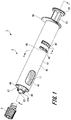
- Fig. 1 is a perspective view illustrating the pharmaceutical liquid administration device according to this embodiment.
- Fig. 2 is a perspective view illustrating a state where an administration component is mounted on the pharmaceutical liquid administration device according to this embodiment.
- Fig. 3 is a cross-sectional view taken along the line K-K illustrated in Fig. 2 .
- Fig. 4 is an exploded perspective view of the pharmaceutical liquid administration device according to this embodiment.
- Fig. 5 is a cross-sectional view taken along the line T-T illustrated in Fig. 1 ; and
- Fig. 6 is an enlarged cross-sectional view of main parts in Fig. 5 .
- Fig. 7 is an enlarged cross-sectional view illustrating a modification of the main parts in Fig. 6 .
- Fig. 1 is a perspective view illustrating the pharmaceutical liquid administration device according to this embodiment.
- Fig. 2 is a perspective view illustrating a state where an administration component is mounted on the pharmaceutical liquid administration device according to this embodiment.
- Fig. 3
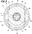
- Fig. 8 is a cross-sectional view taken along the line S-S illustrated in Fig. 1 .
- Figs. 9 , 10 are cross-sectional views illustrating main parts of a pusher member and the syringe holder in the pharmaceutical liquid administration device according to this embodiment.
- Fig. 11 is a front view illustrating the pharmaceutical liquid administration device according to this embodiment.
- a pharmaceutical liquid administration device 1 includes an administration device body 2; and a cap 3 detachably attached to the administration device body 2. As illustrated in Fig. 2 , this pharmaceutical liquid administration device 1 is mounted with an injection needle assembly 90 by screwing the same into a distal end portion of the administration device body 2.
- the injection needle assembly 90 is an example of an administration component, having a needle tube 92.
- the administration device body 2 and the injection needle assembly 90 are included in a pharmaceutical liquid administration set 10.
- the skin is composed of three parts: epidermis, dermis, and subcutaneous tissue.
- the epidermis is a layer having a thickness of about 50 to 200 ⁇ m from a skin surface; and the dermis is a layer having a thickness of about 1.5 to 3.5 mm, continuous from the epidermis.
- An influenza vaccine is typically administered subcutaneously or intramuscularly so that the vaccine is administered to a lower part of the skin or deeper.
- the pharmaceutical liquid administration device 1 is used for intradermal injection with respect to the upper part of the skin as a target site.
- the injection needle assembly 90 is provided with a male threaded portion 91, an example of a screwed portion, and an engaging portion 90a. Furthermore, the injection needle assembly 90 is housed in a storage case 93.
- the storage case 93 is formed in a hollow cylindrical shape with a proximal end portion opened and a distal end portion closed. As illustrated in Fig. 3 , a cylindrical hole in the storage case 93 includes an engaged portion 93a which is to be engaged with the engaging portion 90a of the injection needle assembly 90. Accordingly, the injection needle assembly 90 rotates together with the storage case 93 when the injection needle assembly 90 is mounted on the administration device body 2 of the pharmaceutical liquid administration device 1 by screwing.
- an outer diameter of a cylindrical portion that houses the injection needle assembly 90 is set, for example, within a range of 10 to 30 mm.
- the administration device body 2 includes a syringe 11; a pusher member 12; and a syringe holder 13 that holds the syringe 11.
- the syringe 11 is a prefilled syringe filled with a pharmaceutical liquid P in advance.
- the syringe 11 includes a body section 21 formed in a substantially cylindrical shape; a discharge portion 22 formed at a distal end portion of the body section 21; and a gasket 31.
- the gasket 31 is slidably disposed in a cylindrical hole 21a of the body section 21.
- the gasket 31 is formed in a substantially columnar shape.
- the gasket 31 moves while being in contact with an inner peripheral surface of the cylindrical hole 21a of the body section 21 in a liquid-tight manner.
- the gasket 31 partitions a space in the cylindrical hole 21a of the body section 21 into two.
- a space inside the discharge portion 22 as well as a space inside the body section 21 from the gasket 31 to the discharge portion 22 are included in a liquid chamber 23 filled with the pharmaceutical liquid P.
- a space inside the body section 21 from the gasket 31 to the other end is where a pusher body 34 (to be mentioned) of the pusher member 12 is to be disposed.
- One end portion of the gasket 31 is formed into a tapered shape having a diameter continuously decreasing toward a distal end.
- This tapered shape corresponds to a shape of an inner surface in the distal end portion of the body section 21. Therefore, when the gasket 31 is moved to a side closer to the distal end portion of the body section 21, one end portion of the gasket 31 comes into contact with the inner surface in the distal end portion of the body section 21 so as not to generate a gap.
- a material of the gasket 31 is not specifically limited, but an elastic material is preferable in order to improve liquid tightness with respect to the body section 21.
- the elastic material include various rubber materials such as natural rubber, isobutylene rubber, and silicone rubber, various thermoplastic elastomers such as thermoplastic olefin and thermoplastic styrene, and mixtures thereof.
- an inner diameter and an outer diameter are appropriately set in accordance with use application or a volume of the pharmaceutical liquid filled in the liquid chamber 23.
- the inner diameter of the body section 21 is preferably set within a range of 4.4 to 5.0 mm, and the outer diameter within a range of 6.6 to 8.4 mm.
- the inner diameter of the body section 21 is preferably set within a range of 6.1 to 9.0 mm, and the outer diameter within a range of 7.9 to 12.5 mm.
- Examples of the pharmaceutical liquid P include various vaccines for preventing various infectious diseases such as influenza, but the pharmaceutical liquid P is not limited to vaccines.
- examples of the pharmaceutical liquid P include injection solutions of glucide such as glucose, injection solutions for correcting electrolytes such as sodium chloride and potassium lactate, vitamins, antibiotic injection solutions, contrast media, steroids, proteolytic enzyme inhibitors, fat emulsions, anticancer agents, anesthetics, heparin calcium, and antibody drugs.
- the body section 21 is provided with a flange 24 in its proximal end portion.
- the flange 24 protrudes outward in a radial direction from an outer peripheral surface of the proximal end portion of the body section 21.
- the flange 24 has long diameter portions 24a which are apart from a central axis of the body section 21 by a predetermined distance; and short diameter portions 24b which are apart from the central axis by a distance shorter than the distance of the long diameter portions 24a.
- the two long diameter portions 24a are respectively fixed with two fixing claws 43 (to be mentioned) of a barrel body 41 included in the syringe holder 13.
- the maximum outer diameter of the flange 24, that is, a distance between the pair of long diameter portions 24a is set, for example, within a range of 10 to 20 mm.
- the long diameter portions 24a are formed in an arc shape with the central axis of the body section 21 serving as the center, and the short diameter portions 24b are formed in a linear shape in a planar view from the proximal end portion.
- the flange 24 is formed with an opening 24c communicating with the cylindrical hole 21a of the body section 21.
- the opening 24c opens in a circular shape, and the pusher body 34 (to be mentioned) of the pusher member 12 is inserted into the opening 24c.
- the discharge portion 22 is continuously disposed in one end of the body section 21, being formed in a substantially cylindrical shape coaxial with the body section 21.
- the discharge portion 22 is formed in a tapered shape in which a diameter continuously decreases toward the distal end opposite to the body section 21.
- the discharge portion 22 includes a cylindrical hole 22a communicating with the cylindrical hole 21a of the body section 21.
- the discharge portion 22 is coupled with a Luer-Lok portion 26, an example of a screwing portion.
- the Luer-Lok portion 26 includes a cylindrical portion 27 having a cylindrical shape, coaxially surrounding the discharge portion 22.
- the cylindrical portion 27 has a circular inner periphery and a hexagonal outer periphery.
- the inner peripheral surface of the cylindrical portion 27 is formed with a female threaded portion 27a.
- the female threaded portion 27a is formed to be screwed with the male threaded portion 91 provided to the injection needle assembly 90.
- the injection needle assembly 90 is attached to a distal end portion of the syringe 11. Accordingly, a needle hole of the needle tube 92 in the injection needle assembly 90 and the inside of the discharge portion 22 are communicated with each other in a liquid-tight manner.
- Examples of a material of the syringe 11 include various resin such as polyvinyl chloride, polyethylene, polypropylene, cyclic polyolefin, polystyrene, poly-(4-methylpentene-1), polycarbonate, acrylic resin, acrylonitrile-butadiene-styrene copolymer, polyester such as polyethylene terephthalate, and also include butadiene-styrene copolymer, and polyamide (for example, nylon-6, nylon-6, 6, nylon-6, 10, and nylon-12).
- resin such as polypropylene, cyclic polyolefin, polyester, poly- (4-methylpentene-1) from a viewpoint of moldability. It is preferable that the material of the syringe 11 is substantially transparent in order to ensure the visibility of the inside.
- the pusher member 12 includes a pusher body 34 to press the gasket 31; an operating portion 35; a lock portion 36; a first collar 37; and a second collar 38.
- the pusher body 34 is formed in a substantially rod-like shape whose cross-sectional shape in a direction orthogonal to an axial direction of the pusher body 34 is substantially formed in a cross shape.
- the pusher body 34 is inserted into the body section 21 from the opening 24c of the syringe 11, being mostly disposed inside the body section 21 of the syringe 11.
- a distal end face of the pusher body 34 is formed in a substantially circular shape. As the operating portion 35 (to be mentioned) is pushed in the distal end direction, the distal end face of the pusher body 34 comes into contact with the gasket 31 disposed inside the body section 21 of the syringe 11, which causes the gasket 31 to slide in the distal end direction.
- the pusher body 34 has an outer diameter d1 set within a range of 0.01 to 3 mm smaller than the inner diameter of the body section 21 (see Fig. 13 ). Specifically, in a case where the volume of the pharmaceutical liquid filled in the liquid chamber 23 is 0.5 mL, the outer diameter d1 of the pusher body 34 is preferably set within a range of 1.5 to 4.9 mm, and in a case where the volume of the pharmaceutical liquid filled in the liquid chamber 23 is 1.0 mL, the outer diameter d1 is preferably set within a range of 3.2 to 8.8 mm.
- the pusher body 34 has a length L4, an axial length from the distal end of the pusher body 34 to the first collar 37 (to be mentioned), which is substantially equivalent to an axial length of the body section 21 of the syringe 11 (see Fig. 14 ) .
- the axial length L4 of the pusher body 34 is preferably set within a range of 30 to 60 mm.
- the length L4 of the pusher body 34 is preferably set within a range of 8 to 25 times the size of the outer diameter d1.
- the operating portion 35, lock portion 36, first collar 37, and second collar 38 are disposed in a proximal end portion of the pusher body 34 in the following order, that is, the first collar 37, lock portion 36, second collar 38, and operating portion 35.
- the first collar 37 and second collar 38 are formed in a rectangular flat plate shape.
- the first collar 37 and second collar 38 protrude from side surfaces of the pusher body 34 in a direction orthogonal to the axial direction of the pusher body 34.
- the first collar 37 is provided with an anti-drop projection 37a at an edge portion.
- the anti-drop projection 37a protrudes from the edge portion of the first collar 37, being disposed in parallel to a plane of the first collar 37.
- the lock portion 36 protrudes from a side surface of the pusher body 34 in a direction orthogonal to the axial direction of the pusher body 34.
- the lock portion 36 includes an inclined portion 36a, and an elastic portion 36b.
- the inclined portion 36a is inclined inward in the distal end direction, being disposed in a distal end portion of the lock portion 36.
- the elastic portion 36b has elasticity, being disposed in a proximal end portion of the lock portion 36.
- the operating portion 35 is formed at the proximal end of the pusher body 34.
- the operating portion 35 is formed in a substantially disk-like shape.
- a user presses the operating portion 35 so that the gasket 31 disposed in the distal end of the pusher body 34 moves inside the cylindrical hole 21a of the body section 21 of the syringe 11.
- polyacetal as well as various resin enumerated as the material of the syringe 11 can be employed.
- the syringe holder 13 includes the barrel body 41; through holes 42 illustrated as an example of deformation promoting portions; the fixing claws 43; rotation restricting portions 44; radial movement-restricting portions 45; a viewing window 46; insertion holes 47; and a holder collar 48.
- the barrel body 41 is formed in a substantially cylindrical shape, being configured to cover the outer peripheral surface of the body section 21 and the flange 24 of the syringe 11 and the outer peripheral surface of the cylindrical portion 27 of the Luer-Lok portion 26.
- the barrel body 41 is configured to be graspable by the user when the injection needle assembly 90 is mounted on the syringe 11.
- a proximal end portion of the barrel body 41 is formed with a holder opening 41a into which the syringe 11 and the pusher member 12 can be inserted.
- the holder opening 41a is placed closer to the distal end than the operating portion 35 which is the proximal end portion of the pusher body 34 inserted into the syringe holder 13.
- the barrel body 41 may cover at least the outer peripheral surface of the flange 24.
- an inner diameter is set larger than the outer diameters of the body section 21, cylindrical portion 27, and flange 24, which is, for example, within a range of 11 to 21 mm. Furthermore, an outer diameter of the barrel body 41 is set, for example, within a range of 15 to 25 mm.
- the viewing window 46 is opened in a distal end portion of the barrel body 41.
- the viewing window 46 is provided to a position where the liquid chamber 23 of the syringe 11 can be viewed from the outside of the syringe holder 13 when the syringe 11 is mounted on the syringe holder 13. Accordingly, even when the syringe holder 13 is mounted on the syringe 11, it is possible to ensure visibility of the inside.
- the holder collar 48 is provided to the proximal end portion of the barrel body 41.
- the holder collar 48 protrudes substantially perpendicularly from a part of an outer peripheral surface of the barrel body 41. Due to the holder collar 48, when the user grips the syringe holder 13 and administers the pharmaceutical liquid, it is possible to prevent the finger holding the syringe holder 13 from slipping toward the proximal end. It is also possible to prevent the pharmaceutical liquid administration device 1 from rolling over when placing the pharmaceutical liquid administration device 1 on a desk and the like.
- the two fixing claws 43 are provided protruding from an inner wall of the barrel body 41 in a middle part in an axial direction of the inner wall of the barrel body 41.
- the two fixing claws 43 are provided at positions in the inner wall of the barrel body 41 where they face each other.
- distal end faces of the fixing claws 43 face a proximal end face of the flange 24 continuing to the long diameter portions 24a.
- fixing projections 51 are provided to a side closer to the distal end than the two fixing claws 43.
- the flange 24 climbs over the fixing claws 43 and is fitted between the fixing claws 43 and the fixing projections 51. Accordingly, the syringe 11 is restricted to move axially with respect to the syringe holder 13.
- the number of the fixing claws 43 is described to be two as an example, but the present invention is not limited thereto, and the number of the fixing claws 43 may be three or more.
- through holes 42 are respectively provided close to the two fixing claws 43.
- the through holes 42 are formed at a side closer to the distal end than the fixing claws 43. In other words, the through holes 42 are provided at positions farther from the holder opening 41a than the fixing claws 43.
- the through holes 42 are opened, having a predetermined length along a circumferential direction of the barrel body 41.
- the long diameter portions 24a of the flange 24 face the through holes 42. Since the through holes 42 are provided close to the fixing claws 43, when the long diameter portions 24a of the flange 24 climb over the fixing claws 43, the fixing claws 43 are easily deformed outward in a radial direction of the barrel body 41. Accordingly, it possible to prevent damages on the flange 24 and the fixing claws 43 when the long diameter portions 24a of the flange 24 climb over the fixing claws 43.
- the two through holes 42 has a length in the circumferential direction of the barrel body 41 set within a range of 9 to 25 mm.
- the circumferential length of each of the two through holes 42 is set to 15 to 35% of an outer peripheral length of the barrel body 41. Accordingly, it is possible to maintain strength of the barrel body 41 while promoting the outward deformation of the fixing claws 43 in the radial direction of the barrel body 41.
- the deformation promoting portions are described as the through holes 42 penetrating side walls of the barrel body 41, but the present invention is not limited thereto.
- the deformation promoting portions may have any shape as long as the fixing claws 43 are easily deformed outward in the radial direction of the barrel body 41 when the long diameter portions 24a of the flange 24 climb over the fixing claws 43. Therefore, the long diameter portions 24a may be thin-thickness portions formed by reducing the inner wall of the barrel body 41, that is specifically, recessed portions provided to the inner wall of the barrel body 41.
- Each of the two through holes 42 is provided with the radial movement-restricting portion 45.
- the radial movement-restricting portions 45 are provided in the middle of the through holes 42 in the circumferential direction.
- the radial movement-restricting portions 45 extend from distal ends of the fixing claws 43 in the distal end direction so as to close a part of the through holes 42, serving as projections that connect distal ends of the through holes 42 and proximal ends thereof.
- the radial movement-restricting portions 45 are brought into contact with or disposed close to the long diameter portions 24a of the flange 24.
- a force represented by the arrow B illustrated in Fig. 8 or a force in a direction in which a central axis Q of the syringe 11 is decentered, is applied to the syringe 11.
- a force is applied to the syringe 11 in the radial direction. Therefore, the syringe 11 may move in the radial direction, and the flange 24 may thrust into the through holes 42.
- the radial movement-restricting portions 45 are brought into contact with the long diameter portions 24a of the flange 24 so that the syringe 11 is restricted to move in the radial direction.
- distal end portions of the radial movement-restricting portions 45 are formed thinner than proximal end portions which are to be brought into contact with the long diameter portions 24a of the flange 24. Accordingly, it becomes difficult to restrict the fixing claws 43 to deform outward in the radial direction of the barrel body 41, and it is possible to reliably restrict the syringe 11 to move in the radial direction when the long diameter portions 24a of the flange 24 climb over the fixing claws 43.
- the radial movement-restricting portions 45 are described as parts that connect distal end portions and proximal end portions of the through holes 42, but the present invention is not limited thereto.
- the radial movement-restricting portions 45 may not be configured to connect the distal end portions and the proximal end portions of the through holes 42.
- the radial movement-restricting portions 45 may extend in the distal end direction from the distal ends of the fixing claws 43 to part of the way in an axial direction of the through holes 42 so as to close a part of the through holes 42.
- the radial movement-restricting portions 45 may have a shape with thin distal end portions omitted.
- the two insertion holes 47 are formed, penetrating the side walls of the barrel body 41 in a side close to the holder opening 41a of the opening 24c of the syringe 11 which is held inside the barrel body 41.
- the two insertion holes 47 are arranged to face each other.
- the insertion holes 47 are formed at a side closer to the proximal end of the barrel body 41 than the fixing claws 43 and the through holes 42.
- Each length L1 in a direction orthogonal to an axial direction of the two insertion holes 47 is set larger than the outer diameter d1 of the pusher body 34. It is preferable that the length L1 is substantially equivalent to a distance between the two short diameter portions 24b of the flange 24, which are facing each other.
- the number of the insertion holes 47 provided to the barrel body 41 is described to be two as an example, but the present invention is not limited thereto.
- Three or more insertion holes 47 into which the guide members 101 are inserted may be provided to the barrel body 41. In a case where three or more insertion holes 47 are provided, it is preferable to arrange the insertion holes 47 at equal intervals in the circumferential direction of the barrel body 41 in order to guide the pusher body 34 in a well-balanced manner.
- the rotation restricting portions 44 are provided between the two through holes 42 in the inner wall of the barrel body 41.
- the rotation restricting portions 44 are four ribs protruding from an inner wall surface of the barrel body 41.
- the rotation restricting portions 44 are brought into contact with or disposed close to the short diameter portions 24b of the flange 24.
- the rotation restricting portions 44 are brought into contact with the short diameter portions 24b of the flange 24 inserted into the barrel body 41 so as to restrict the rotation of the syringe 11 in the circumferential direction with respect to the syringe holder 13.
- the rotation restricting portions 44 extend from the vicinity of the through holes 42, having a predetermined length toward the holder opening 41a of the barrel body 41. Accordingly, when the syringe 11 is inserted from the holder opening 41a, the rotation restricting portions 44 are brought into contact with the short diameter portions 24b of the flange 24 so as to restrict the rotation of the syringe 11 in the circumferential direction with respect to the syringe holder 13.
- each of the rotation restricting portions 44 is provided with a contact projection 44a which is to be brought into contact with each of the short diameter portions 24b of the flange 24. Accordingly, it is possible to restrict the syringe 11 more reliably to rotate in the circumferential direction with respect to the syringe holder 13. As the contact projections 44a and the flange 24 are brought into contact with each other, it is also possible to prevent the syringe 11 from rattling inside the barrel body 41.
- the first collar 37 of the pusher member 12 is brought into contact with the rotation restricting portions 44. Accordingly, it is possible to prevent the pusher member 12 from rattling inside the barrel body 41.
- the inner wall of the barrel body 41 is provided with protuberant portion 52 in a side closer to the proximal end portion.
- the protuberant portion 52 is provided between two adjacent rotation restricting portions 44 of the four rotation restricting portions 44.
- the protuberant portion 52 is a protrusion projecting inward in the radial direction from the inner wall of the barrel body 41.
- a distal end portion of the protuberant portion 52 projects substantially perpendicularly from the inner wall of the barrel body 41, while a proximal end portion thereof is inclined with respect to the inner wall of the barrel body 41.
- the anti-drop projection 37a climbs over the protuberant portion 52 and moves in a direction closer to the distal end portion than the protuberant portion 52.
- the anti-drop projection 37a can be brought into contact with the protuberant portion 52 from a side closer to the distal end, that is, from a side opposite to the holder opening 41a. Accordingly, it is possible to prevent the pusher member 12 from falling off the barrel body 41.
- the lock portion 36 of the pusher member 12 climbs over the protuberant portion 52 of the syringe holder 13 as illustrated in Fig. 10 .
- the lock portion 36 climbs over the protuberant portion 52, the inclined portion 36a of the lock portion 36 is pressed against the protuberant portion 52, and the elastic portion 36b is elastically deformed.
- the elastic deformation of the elastic portion 36b returns to its original state.
- the operating portion 35 transmits a clicky touch or a clicking sound to the user. Accordingly, it is possible to inform the user that the injection and administration of the pharmaceutical liquid have been completed.
- the lock portion 36 climbs over the protuberant portion 52, the lock portion 36 is fixed to the protuberant portion 52. Therefore, the pusher member 12 is restricted to move in a direction closer to the proximal end, that is, in a direction close to the holder opening 41a. Accordingly, it is possible to prevent the used pharmaceutical liquid administration device 1 from being reused by mistake. Furthermore, the first collar 37 and the second collar 38 of the pusher member 12 are brought into contact with the rotation restricting portions 44. Accordingly, when the pusher member 12 is operated, it is possible to prevent the pusher member 12 from rattling inside the cylindrical hole of the barrel body 41.
- rib members 54 are provided between the rotation restricting portions 44 and the through holes 42.
- a plurality of rib members 54 is provided to the inner wall surface of the barrel body 41, protruding from the inner wall surface of the barrel body 41.
- the plurality of rib members 54 is brought into contact with the flange 24 of the syringe 11. Accordingly, it is possible to prevent the syringe 11 from rattling inside the cylindrical hole of the barrel body 41.
- a distal end portion in the inner wall of the barrel body 41 is provided with a plurality of inclination restricting ribs 49.
- the plurality of inclination restricting ribs 49 protrudes from the inner wall surface of the barrel body 41, extending from the vicinity of the through holes 42 and the rotation restricting portions 44 to the distal end portion of the barrel body 41.
- the plurality of inclination restricting ribs 49 is arranged so as to surround an outer periphery of the discharge portion 22 of the syringe 11 inserted into the barrel body 41 and the outer periphery of the cylindrical portion 27 of the Luer-Lok portion 26.
- the plurality of inclination restricting ribs 49 is brought into contact with the Luer-Lok portion 26 so as to restrict the inclination of the syringe 11. Accordingly, it possible to prevent the syringe 11 from being inclined inside the cylindrical hole of the barrel body 41 when the pharmaceutical liquid is administered or when the injection needle assembly 90 is attached.
- WO 2013/046855 A describes a technique to cover an outer periphery of an inner structural body corresponding to a syringe, using a gripping member so as to increase a diameter of the entire device.
- a pusher to move a gasket that slides inside the inner structural body.
- the present example also intends to provide a method for manufacturing a syringe holder, a pharmaceutical liquid administration set, and a pharmaceutical liquid administration device in which a distal end of a pusher body can be inserted into an opening of a syringe without deviation.
- Figs. 13 to 17 are views for describing insertion of the pusher member 12.
- the Luer-Lok portion 26 is coupled to the discharge portion 22 of the syringe 11 as illustrated in Fig. 4 .
- a male threaded portion of the cap 3 is screwed into the female threaded portion 27a of the Luer-Lok portion 26, and the cap 3 is mounted on the Luer-Lok portion 26. Accordingly, a discharge port of the discharge portion 22 in the syringe 11 is sealed with a packing provided to the cap 3.
- the pharmaceutical liquid P is filled inside the body section 21 of the syringe 11.
- the gasket 31 is inserted into the body section 21 from the opening 24c of the syringe 11.
- the syringe 11 is supported by a syringe support member (not illustrated), and the syringe 11 is inserted into the cylindrical hole of the barrel body 41 from the holder opening 41a of the barrel body 41 of the syringe holder 13.
- linear portions of the holder collar 48 of the barrel body 41 are oriented to the linear short diameter portions 24b provided to the flange 24 of the syringe 11. Accordingly, it is possible to easily adjust an orientation in the circumferential direction of the syringe 11 with respect to the barrel body 41.
- the length L1 of the insertion holes 47 is substantially equal to the distance between the two opposed short diameter portions 24b of the flange 24, when the syringe 11 is inserted into the cylindrical hole of the barrel body 41, the flange 24 of the syringe 11 hardly enters the insertion holes 47, and the syringe 11 can be easily inserted to a specified position.
- the flange 24 of the syringe 11 is fitted between the fixing claws 43 of the barrel body 41 and the fixing projections 51, and a distal end face and a proximal end face of the flange 24 are fixed by the fixing projections 51 and the fixing claws 43, respectively.
- the fixing claws 43 can be easily elastically deformed by the through holes 42 provided close to end portions of the fixing claws 43 which are opposite to the holder opening 41a.
- the radial movement-restricting portions 45 face the long diameter portions 24a, and the rotation restricting portions 44 face the short diameter portions 24b.
- the syringe holder 13 holding the syringe 11 is supported by a syringe holder support member (not illustrated), and the pusher member 12 is supported by a chuck member 102.
- a pair of guide members 101 is caused to face the insertion holes 47 provided to the syringe holder 13.
- the pusher member 12 supported by the chuck member 102 is inserted into the barrel body 41 from the holder opening 41a of the barrel body 41.
- the pair of guide members 101 is inserted into the barrel body 41 from the insertion holes 47.
- end portions of the guide members 101 facing side surfaces of the pusher member 12 are provided with guide grooves 101a substantially having a V-shape.
- the pair of guide members 101 is disposed so as to sandwich a distal end portion of the pusher body 34 inserted into the barrel body 41.
- the V-shaped guide grooves 101a formed at the end portions, facing the side surfaces of the pusher member 12 are brought into contact with the side surfaces of the distal end portion of the pusher body 34 so that it is possible to align the shaft center of the pusher body 34 with the center of the opening 24c of the syringe 11. Accordingly, it is possible to insert the pusher body 34 into the opening 24c of the syringe 11 without deviation.
- the insertion holes 47 into which the pair of guide members 101 is inserted are disposed close to the fixing claws 43 to fix the flange 24. Since the length L1 of the insertion holes 47 is larger than the outer diameter d1 of the pusher body 34, a width of the guide members 101 can be made larger than the outer diameter d1 of the pusher body 34. Accordingly, it is possible to reliably align the shaft center of the pusher body 34 with the center of the opening 24c of the syringe 11.
- the axial length L4 of the pusher body 34 is set within the range of 8 to 25 times the size of the outer diameter d1, the pusher body 34 is likely to bend at the time of handling. Therefore, as the shaft center of the bent pusher body 34 is corrected by the guide members 101 inserted from the insertion holes 47, it is possible to reliably insert the pusher body 34 into the opening 24c of the syringe 11.
- the shape of the guide grooves 101a formed at the end portions of the guide members 101 facing the side surfaces of the pusher member 12 is not limited to the V-shape, but may be any other shapes such as a trapezoidal shape or an arc shape. Alternatively, the guide grooves 101a may not be provided to the distal end portions of the guide members 101.
- a length L2 of the syringe 11 held by the syringe holder 13 which is from the insertion holes 47 to the opening 24c is set to, for example, a range of 1 to 10 mm. Accordingly, the guide members 101 inserted into the barrel body 41 from the insertion holes 47 can reliably guide the pusher body 34 to the opening 24c of the syringe 11 without interfering with the flange 24 of the syringe 11. Furthermore, when the syringe holder 13 is mounted on the syringe 11, a length L3 from the holder opening 41a of the barrel body 41 to the opening 24c of the syringe 11 is set to, for example, a range of 20 to 60 mm.
- the length L2 is made short to the greatest possible extent in order to prevent deviation of the distal end portion of the pusher body 34 from the opening 24c.
- the length L3 is set to the range of 20 to 60 mm, and the operating portion 35 which is a proximal end portion of the pusher member 12 inserted into the syringe holder 13 is located in a side closer to the proximal end portion than the holder opening 41a so that an axial length of the pusher member 12 is longer than 20 to 60 mm. Therefore, the axial length of the pusher member 12 becomes longer than the pusher body 34 of the pusher member 12, which causes the pusher body 34 to bend easily at the time of handling. Therefore, as the shaft center of the bent pusher body 34 is corrected by the guide members 101 inserted from the insertion holes 47, it is possible to reliably insert the pusher body 34 into the opening 24c of the syringe 11.
- the pusher member 12 is further inserted into the cylindrical hole 21a of the body section 21 of the syringe 11.
- the guide members 101 are pulled out from the insertion holes 47.
- the pusher member 12 is further inserted, and the pusher member 12 is inserted to a predetermined position as illustrated in Fig. 17 , the chuck member 102 supporting the pusher member 12 is separated from the pusher member 12. Accordingly, the assembly of the pharmaceutical liquid administration device 1 is completed.
- the syringe holder 13 As described above, mounting the syringe holder 13 on the syringe 11 increases the diameter of the administration device body 2, which makes it easier to grasp the administration device body 2. Thus, the operability is improved at the time of operating the pusher member 12. According to the pharmaceutical liquid administration device 1 of this embodiment, it is possible to easily mount the syringe holder 13 on a commonly-used syringe without changing the shape of the syringe 11.
- the distal end portion of the administration device body 2 that is, the Luer-Lok portion 26 of the syringe 11 is brought into contact with the injection needle assembly 90 stored in the storage case 93. Then, the female threaded portion 27a of the Luer-Lok portion 26 and the male threaded portion 91 provided to the injection needle assembly 90 are screwed together. At this time, mounting the syringe holder 13 on the syringe 11 increases the diameter of the administration device body 2, which makes it easier to screw the injection needle assembly 90 and the syringe 11 together.
- the outer diameter of the storage case 93 is set larger than the outer diameter of the flange 24 of the syringe 11.
- the storage case 93 rotates together with the injection needle assembly 90 due to the engaged portion 93a engaged with the engaging portion 90a of the injection needle assembly 90. Therefore, when the injection needle assembly 90 is screwed, it is possible to increase not only the diameter of the injection needle assembly 90 but also the diameter of the administration device body 2, which makes it easier to screw the injection needle assembly 90 and the syringe 11 together.
- the radial movement-restricting portions 45 and the rotation restricting portions 44 are provided to the barrel body 41 of the syringe holder 13. Therefore, it is possible to prevent the central axis of the syringe 11 from moving in the radial direction inside the cylindrical hole of the barrel body 41 due to rotational torque, and to prevent the syringe 11 from rotating inside the cylindrical hole of the barrel body 41. Accordingly, it possible to prevent the syringe holder 13 from spinning around, and to prevent damages on of the fixing claws 43 of the syringe holder 13 due to the rotation of the syringe 11.
- the pharmaceutical liquid administration device of the present invention is not limited to the above embodiment, and can be variously modified within the scope not deviating from the gist of the invention described in the claims.
- the administration component to be mounted on the administration device body 2 of the pharmaceutical liquid administration device 1 is not limited to the aforementioned injection needle assembly 90.
- an administration component to be mounted on the pharmaceutical liquid administration device 1 other various administration components may be applied as long as they can be mounted by screwing, for example, a needle-free syringe without a needle tube, an intranasal administration device for administering a pharmaceutical liquid to a nasal cavity.
- the Luer-Lok portion 26 is described as a screwing portion, but the present invention is not limited thereto .
- a male threaded portion may be provided to the discharge portion 22, and a female threaded portion may be provided to the administration component so as to screw the both threaded portions.
- the present invention may also employ the following configuration as a means for solving another technical problem to be solved by the aforementioned invention.
- the present invention can be applied to a syringe holder configured to hold a syringe having a distal end portion screwed with an administration component to administer a pharmaceutical liquid, and can be applied to a pharmaceutical liquid administration set provided with this syringe holder.
- the present invention can also be applied to a method for manufacturing a syringe holder having a distal end portion into which an administration component is screwed, being provided to a pharmaceutical liquid administration device for administering a pharmaceutical liquid into a body, and for manufacturing a pharmaceutical liquid administration set provided with this syringe holder, and the pharmaceutical liquid administration device.
Landscapes
- Health & Medical Sciences (AREA)
- Engineering & Computer Science (AREA)
- Veterinary Medicine (AREA)
- Animal Behavior & Ethology (AREA)
- General Health & Medical Sciences (AREA)
- Public Health (AREA)
- Life Sciences & Earth Sciences (AREA)
- Vascular Medicine (AREA)
- Anesthesiology (AREA)
- Biomedical Technology (AREA)
- Heart & Thoracic Surgery (AREA)
- Hematology (AREA)
- Environmental & Geological Engineering (AREA)
- Pharmacology & Pharmacy (AREA)
- Infusion, Injection, And Reservoir Apparatuses (AREA)
Abstract
Description
- The present invention relates to a syringe holder configured to hold a syringe having a distal end portion screwed with an administration component to administer a pharmaceutical liquid, and relates to a pharmaceutical liquid administration set provided with this syringe holder.
- In recent years, a prefilled syringe (pharmaceutical liquid administration device), that is, a syringe prefilled with a pharmaceutical liquid, has come into popular use. Using such a prefilled syringe requires no process to suck a pharmaceutical liquid from a vial into the syringe when administering the pharmaceutical liquid, which shortens the time required for administration.
- A typical prefilled syringe includes a body section and a plunger. When administering a pharmaceutical liquid into a body with the prefilled syringe, the plunger is operated and the pharmaceutical liquid filled in a liquid chamber of the body section is discharged into the body through an injection needle coupled to a distal end of the body section.
- When administering a small amount of pharmaceutical liquid, a small prefilled syringe with a small liquid chamber is used. For example, perpendicularly puncturing the skin with an injection needle to administer a pharmaceutical liquid requires a large injection pressure, and preventing leakage of the pharmaceutical liquid requires the prefilled syringe being pressed against the skin strongly with a stable load. However, the conventional small prefilled syringe has a structure unsuitable for keeping it pressed against the skin with a strong force, which is awkward to use.
- Patent Literature 1 discloses an example of a pharmaceutical liquid administration device with improved operability. This Patent Literature 1 discloses a technique to cover an outer periphery of a prefilled syringe with a syringe holder for covering a needle tube after administration, thereby enlarging a diameter of the entire device. In the technique disclosed in this Patent Literature 1, a lock adapter provided to a distal end portion of the prefilled syringe is screwed with an administration component such as a needle hub having a needle tube so as to attach the administration component to the prefilled syringe.
- Patent Literature 1:
US 2009/0105663 A - However, according to the technique described in Patent Literature 1, covering the syringe with the syringe holder enlarges the diameter of the entire device so that large rotational torque is generated when screwing the needle hub, or the administration component. Therefore, the syringe moves in a radial direction, which may cause damage on a claw portion configured to restrict rotation of the syringe. Accordingly, the syringe rotates inside the syringe holder, and the syringe holder spins around, which is a problem.
- The present invention has been made in view of such situations, and an object of the present invention is to provide a syringe holder and a pharmaceutical liquid administration set which can prevent a syringe from spinning around inside the syringe holder when attaching an administration component.
- In order to solve the aforementioned problem and to achieve the object of the present invention, a syringe holder of the present invention is configured to hold a syringe that comprises a body section having a cylindrical shape capable of being filled with a pharmaceutical liquid therein; a discharge portion formed at a distal end portion of the body section; a flange that is formed at a proximal end portion of the body section and includes a long diameter portion apart from a central axis of the body section by a predetermined distance and a short diameter portion apart from the central axis by a distance shorter than the predetermined distance of the long diameter portion; and a screwing portion that is provided to the discharge portion and is configured to screw an administration component to administer the pharmaceutical liquid to a biological body.
- The syringe holder includes a barrel body, a holder opening, a fixing claw, a fixing projection, a deformation promoting portion, a rotation restricting portion, and a radial movement-restricting portion.
- The barrel body is formed in a cylindrical shape, covering at least an outer peripheral surface of the flange of the syringe. The holder opening is provided to the barrel body and the syringe is inserted. The fixing claw fixes a surface of the flange in a side close to the holder opening. The fixing projection fixes a surface of the flange in a side opposite to the surface in the side close to the holder opening. The deformation promoting portion is provided close to an end portion of the fixing claw in a side opposite to the holder opening, being configured to promote the fixing claw to deform outward in a radial direction of the barrel body when the long diameter portion of the syringe inserted from the holder opening climbs over the fixing claw. Being brought into contact with the short diameter portion, the rotation restricting portion restricts the syringe from rotating in a circumferential direction with respect to the barrel body. The radial movement-restricting portion is provided close to the deformation promoting portion. Being brought into contact with the long diameter portion, the radial movement-restricting portion restricts the syringe from moving in the radial direction with respect to the barrel body.
- Furthermore, a pharmaceutical liquid administration set of the present invention is provided with a syringe and a syringe holder. The syringe and the syringe holder described above are used herein.
- According to a syringe holder and a pharmaceutical liquid administration set of the present invention, it is possible to prevent the syringe holder from spinning around when attaching an administration component to a syringe.
-
-
Fig. 1 is a perspective view illustrating a pharmaceutical liquid administration device including a syringe holder according to an embodiment of the present invention. -
Fig. 2 is a perspective view illustrating a state where an administration component is mounted on the pharmaceutical liquid administration device according to the embodiment of the present invention. -
Fig. 3 is a cross-sectional view taken along the line K-K illustrated inFig. 2 . -
Fig. 4 is an exploded perspective view illustrating the pharmaceutical liquid administration device according to the embodiment of the present invention. -
Fig. 5 is a cross-sectional view taken along the line T-T illustrated inFig. 1 . -
Fig. 6 is an enlarged cross-sectional view of main parts inFig. 5 . -
Fig. 7 is an enlarged cross-sectional view illustrating main parts of a syringe holder according to a modification of the embodiment of the present invention. -
Fig. 8 is a cross-sectional view taken along the line S-S illustrated inFig. 1 . -
Fig. 9 is an enlarged cross-sectional view illustrating main portions of the syringe holder and a pusher member according to the embodiment of the present invention. -
Fig. 10 is a cross-sectional view illustrating a state where the pusher member is slid from the state illustrated inFig. 9 . -
Fig. 11 is a front view illustrating the pharmaceutical liquid administration device according to the embodiment of the present invention. -
Fig. 12 is a perspective view for describing a state where the pusher member is to be mounted on the pharmaceutical liquid administration device according to the embodiment of the present invention. -
Fig. 13 is a perspective view illustrating a state right before the pusher member being mounted on the pharmaceutical liquid administration device according to the embodiment of the present invention. -
Fig. 14 is an enlarged perspective view illustrating main parts in a state where the pusher member is mounted on the pharmaceutical liquid administration device according to the embodiment of the present invention. -
Fig. 15 is a cross-sectional view taken along the line H-H illustrated inFig. 13 . -
Fig. 16 is a cross-sectional view taken along the line G-G illustrated inFig. 13 . -
Fig. 17 is a perspective view illustrating a state after the pusher member being mounted on the pharmaceutical liquid administration device according to the embodiment of the present invention. - Hereinafter, an embodiment of a syringe holder and a pharmaceutical liquid administration set according to the present invention will be described with reference to
Figs. 1 to 17 . In each of the drawings, the same members are denoted with the same reference numerals. It should be noted that the present invention is not limited to the following embodiment. - The description will be given in the following order.
- 1. Embodiment
- 1-1. Configuration of Pharmaceutical Liquid Administration Device
- 1-2. Assembling of Pharmaceutical Liquid Administration Device (Method for Manufacturing Pharmaceutical Liquid Administration Device)
- With reference to
Figs. 1 to 11 , hereinafter described is a configuration of a pharmaceutical liquid administration device having a syringe holder according to an embodiment of the present invention (hereinafter referred to as "this embodiment"). -
Fig. 1 is a perspective view illustrating the pharmaceutical liquid administration device according to this embodiment.Fig. 2 is a perspective view illustrating a state where an administration component is mounted on the pharmaceutical liquid administration device according to this embodiment.Fig. 3 is a cross-sectional view taken along the line K-K illustrated inFig. 2 .Fig. 4 is an exploded perspective view of the pharmaceutical liquid administration device according to this embodiment.Fig. 5 is a cross-sectional view taken along the line T-T illustrated inFig. 1 ; andFig. 6 is an enlarged cross-sectional view of main parts inFig. 5 .Fig. 7 is an enlarged cross-sectional view illustrating a modification of the main parts inFig. 6 .Fig. 8 is a cross-sectional view taken along the line S-S illustrated inFig. 1 .Figs. 9 ,10 are cross-sectional views illustrating main parts of a pusher member and the syringe holder in the pharmaceutical liquid administration device according to this embodiment.Fig. 11 is a front view illustrating the pharmaceutical liquid administration device according to this embodiment. - As illustrated in
Fig. 1 , a pharmaceutical liquid administration device 1 includes anadministration device body 2; and acap 3 detachably attached to theadministration device body 2. As illustrated inFig. 2 , this pharmaceutical liquid administration device 1 is mounted with aninjection needle assembly 90 by screwing the same into a distal end portion of theadministration device body 2. Theinjection needle assembly 90 is an example of an administration component, having aneedle tube 92. Theadministration device body 2 and theinjection needle assembly 90 are included in a pharmaceutical liquid administration set 10. - Herein, the skin is composed of three parts: epidermis, dermis, and subcutaneous tissue. The epidermis is a layer having a thickness of about 50 to 200 µm from a skin surface; and the dermis is a layer having a thickness of about 1.5 to 3.5 mm, continuous from the epidermis. An influenza vaccine is typically administered subcutaneously or intramuscularly so that the vaccine is administered to a lower part of the skin or deeper.
- Meanwhile, it has been studied to administer an influenza vaccine to an upper part of the skin including many immunocompetent cells as a target site so as to reduce an injected quantity of the vaccine. Note that the upper part of the skin refers to epidermis and dermis of the skin. The pharmaceutical liquid administration device 1 according to this embodiment is used for intradermal injection with respect to the upper part of the skin as a target site.
- The
injection needle assembly 90 is provided with a male threadedportion 91, an example of a screwed portion, and anengaging portion 90a. Furthermore, theinjection needle assembly 90 is housed in astorage case 93. - The
storage case 93 is formed in a hollow cylindrical shape with a proximal end portion opened and a distal end portion closed. As illustrated inFig. 3 , a cylindrical hole in thestorage case 93 includes an engagedportion 93a which is to be engaged with the engagingportion 90a of theinjection needle assembly 90. Accordingly, theinjection needle assembly 90 rotates together with thestorage case 93 when theinjection needle assembly 90 is mounted on theadministration device body 2 of the pharmaceutical liquid administration device 1 by screwing. In regard to thestorage case 93, an outer diameter of a cylindrical portion that houses theinjection needle assembly 90 is set, for example, within a range of 10 to 30 mm. - As illustrated in
Fig. 4 , theadministration device body 2 includes asyringe 11; apusher member 12; and asyringe holder 13 that holds thesyringe 11. - The
syringe 11 is a prefilled syringe filled with a pharmaceutical liquid P in advance. Thesyringe 11 includes abody section 21 formed in a substantially cylindrical shape; adischarge portion 22 formed at a distal end portion of thebody section 21; and agasket 31. - The
gasket 31 is slidably disposed in acylindrical hole 21a of thebody section 21. Thegasket 31 is formed in a substantially columnar shape. Thegasket 31 moves while being in contact with an inner peripheral surface of thecylindrical hole 21a of thebody section 21 in a liquid-tight manner. As illustrated inFig. 5 , thegasket 31 partitions a space in thecylindrical hole 21a of thebody section 21 into two. A space inside thedischarge portion 22 as well as a space inside thebody section 21 from thegasket 31 to thedischarge portion 22 are included in aliquid chamber 23 filled with the pharmaceutical liquid P. On the other hand, a space inside thebody section 21 from thegasket 31 to the other end is where a pusher body 34 (to be mentioned) of thepusher member 12 is to be disposed. - One end portion of the
gasket 31 is formed into a tapered shape having a diameter continuously decreasing toward a distal end. This tapered shape corresponds to a shape of an inner surface in the distal end portion of thebody section 21. Therefore, when thegasket 31 is moved to a side closer to the distal end portion of thebody section 21, one end portion of thegasket 31 comes into contact with the inner surface in the distal end portion of thebody section 21 so as not to generate a gap. - A material of the
gasket 31 is not specifically limited, but an elastic material is preferable in order to improve liquid tightness with respect to thebody section 21. Examples of the elastic material include various rubber materials such as natural rubber, isobutylene rubber, and silicone rubber, various thermoplastic elastomers such as thermoplastic olefin and thermoplastic styrene, and mixtures thereof. - In regard to the
body section 21, an inner diameter and an outer diameter are appropriately set in accordance with use application or a volume of the pharmaceutical liquid filled in theliquid chamber 23. For example, in a case where the volume is set to 0.5 mL, the inner diameter of thebody section 21 is preferably set within a range of 4.4 to 5.0 mm, and the outer diameter within a range of 6.6 to 8.4 mm. In a case where the volume is set to 1 mL, the inner diameter of thebody section 21 is preferably set within a range of 6.1 to 9.0 mm, and the outer diameter within a range of 7.9 to 12.5 mm. - Examples of the pharmaceutical liquid P include various vaccines for preventing various infectious diseases such as influenza, but the pharmaceutical liquid P is not limited to vaccines. Other than vaccines, examples of the pharmaceutical liquid P include injection solutions of glucide such as glucose, injection solutions for correcting electrolytes such as sodium chloride and potassium lactate, vitamins, antibiotic injection solutions, contrast media, steroids, proteolytic enzyme inhibitors, fat emulsions, anticancer agents, anesthetics, heparin calcium, and antibody drugs.
- Furthermore, the
body section 21 is provided with aflange 24 in its proximal end portion. Theflange 24 protrudes outward in a radial direction from an outer peripheral surface of the proximal end portion of thebody section 21. Theflange 24 haslong diameter portions 24a which are apart from a central axis of thebody section 21 by a predetermined distance; andshort diameter portions 24b which are apart from the central axis by a distance shorter than the distance of thelong diameter portions 24a. - A pair of the
long diameter portions 24a and a pair of theshort diameter portions 24b face each other across the central axis . The twolong diameter portions 24a are respectively fixed with two fixing claws 43 (to be mentioned) of abarrel body 41 included in thesyringe holder 13. - The maximum outer diameter of the
flange 24, that is, a distance between the pair oflong diameter portions 24a is set, for example, within a range of 10 to 20 mm. In this embodiment, thelong diameter portions 24a are formed in an arc shape with the central axis of thebody section 21 serving as the center, and theshort diameter portions 24b are formed in a linear shape in a planar view from the proximal end portion. - The
flange 24 is formed with anopening 24c communicating with thecylindrical hole 21a of thebody section 21. Theopening 24c opens in a circular shape, and the pusher body 34 (to be mentioned) of thepusher member 12 is inserted into theopening 24c. - The
discharge portion 22 is continuously disposed in one end of thebody section 21, being formed in a substantially cylindrical shape coaxial with thebody section 21. Thedischarge portion 22 is formed in a tapered shape in which a diameter continuously decreases toward the distal end opposite to thebody section 21. Thedischarge portion 22 includes acylindrical hole 22a communicating with thecylindrical hole 21a of thebody section 21. - The
discharge portion 22 is coupled with a Luer-Lok portion 26, an example of a screwing portion. The Luer-Lok portion 26 includes acylindrical portion 27 having a cylindrical shape, coaxially surrounding thedischarge portion 22. Thecylindrical portion 27 has a circular inner periphery and a hexagonal outer periphery. As illustrated inFig. 5 , the inner peripheral surface of thecylindrical portion 27 is formed with a female threadedportion 27a. The female threadedportion 27a is formed to be screwed with the male threadedportion 91 provided to theinjection needle assembly 90. As the Luer-Lok portion 26 is screwed with theinjection needle assembly 90, theinjection needle assembly 90 is attached to a distal end portion of thesyringe 11. Accordingly, a needle hole of theneedle tube 92 in theinjection needle assembly 90 and the inside of thedischarge portion 22 are communicated with each other in a liquid-tight manner. - Examples of a material of the
syringe 11 include various resin such as polyvinyl chloride, polyethylene, polypropylene, cyclic polyolefin, polystyrene, poly-(4-methylpentene-1), polycarbonate, acrylic resin, acrylonitrile-butadiene-styrene copolymer, polyester such as polyethylene terephthalate, and also include butadiene-styrene copolymer, and polyamide (for example, nylon-6, nylon-6, 6, nylon-6, 10, and nylon-12). Among these examples, it is preferable to use resin such as polypropylene, cyclic polyolefin, polyester, poly- (4-methylpentene-1) from a viewpoint of moldability. It is preferable that the material of thesyringe 11 is substantially transparent in order to ensure the visibility of the inside. - The
pusher member 12 includes apusher body 34 to press thegasket 31; an operatingportion 35; alock portion 36; afirst collar 37; and asecond collar 38. Thepusher body 34 is formed in a substantially rod-like shape whose cross-sectional shape in a direction orthogonal to an axial direction of thepusher body 34 is substantially formed in a cross shape. Thepusher body 34 is inserted into thebody section 21 from theopening 24c of thesyringe 11, being mostly disposed inside thebody section 21 of thesyringe 11. - A distal end face of the
pusher body 34 is formed in a substantially circular shape. As the operating portion 35 (to be mentioned) is pushed in the distal end direction, the distal end face of thepusher body 34 comes into contact with thegasket 31 disposed inside thebody section 21 of thesyringe 11, which causes thegasket 31 to slide in the distal end direction. - The
pusher body 34 has an outer diameter d1 set within a range of 0.01 to 3 mm smaller than the inner diameter of the body section 21 (seeFig. 13 ). Specifically, in a case where the volume of the pharmaceutical liquid filled in theliquid chamber 23 is 0.5 mL, the outer diameter d1 of thepusher body 34 is preferably set within a range of 1.5 to 4.9 mm, and in a case where the volume of the pharmaceutical liquid filled in theliquid chamber 23 is 1.0 mL, the outer diameter d1 is preferably set within a range of 3.2 to 8.8 mm. - The
pusher body 34 has a length L4, an axial length from the distal end of thepusher body 34 to the first collar 37 (to be mentioned), which is substantially equivalent to an axial length of thebody section 21 of the syringe 11 (seeFig. 14 ) . Specifically, the axial length L4 of thepusher body 34 is preferably set within a range of 30 to 60 mm. Furthermore, the length L4 of thepusher body 34 is preferably set within a range of 8 to 25 times the size of the outer diameter d1. - The operating
portion 35,lock portion 36,first collar 37, andsecond collar 38 are disposed in a proximal end portion of thepusher body 34 in the following order, that is, thefirst collar 37,lock portion 36,second collar 38, and operatingportion 35. - The
first collar 37 andsecond collar 38 are formed in a rectangular flat plate shape. Thefirst collar 37 andsecond collar 38 protrude from side surfaces of thepusher body 34 in a direction orthogonal to the axial direction of thepusher body 34. Thefirst collar 37 is provided with ananti-drop projection 37a at an edge portion. Theanti-drop projection 37a protrudes from the edge portion of thefirst collar 37, being disposed in parallel to a plane of thefirst collar 37. When thepusher body 34 is inserted into thecylindrical hole 21a of thebody section 21, theanti-drop projection 37a comes into contact with a protuberant portion 52 (to be mentioned) of thesyringe holder 13. Accordingly, it is possible to prevent thepusher member 12 from falling off thesyringe 11 and thesyringe holder 13. Thelock portion 36 is provided between thefirst collar 37 andsecond collar 38. - The
lock portion 36 protrudes from a side surface of thepusher body 34 in a direction orthogonal to the axial direction of thepusher body 34. Thelock portion 36 includes aninclined portion 36a, and anelastic portion 36b. Theinclined portion 36a is inclined inward in the distal end direction, being disposed in a distal end portion of thelock portion 36. Theelastic portion 36b has elasticity, being disposed in a proximal end portion of thelock portion 36. When pushing thegasket 31 to the end, thelock portion 36 is fixed with the protuberant portion 52 (to be mentioned) of the syringe holder 13 (seeFig. 11 ) . - The operating
portion 35 is formed at the proximal end of thepusher body 34. The operatingportion 35 is formed in a substantially disk-like shape. When using the pharmaceutical liquid administration device 1, a user presses the operatingportion 35 so that thegasket 31 disposed in the distal end of thepusher body 34 moves inside thecylindrical hole 21a of thebody section 21 of thesyringe 11. As a material of thispusher member 12, polyacetal as well as various resin enumerated as the material of thesyringe 11 can be employed. - The
syringe holder 13 includes thebarrel body 41; throughholes 42 illustrated as an example of deformation promoting portions; the fixingclaws 43;rotation restricting portions 44; radial movement-restrictingportions 45; aviewing window 46; insertion holes 47; and aholder collar 48. - The
barrel body 41 is formed in a substantially cylindrical shape, being configured to cover the outer peripheral surface of thebody section 21 and theflange 24 of thesyringe 11 and the outer peripheral surface of thecylindrical portion 27 of the Luer-Lok portion 26. Thebarrel body 41 is configured to be graspable by the user when theinjection needle assembly 90 is mounted on thesyringe 11. A proximal end portion of thebarrel body 41 is formed with aholder opening 41a into which thesyringe 11 and thepusher member 12 can be inserted. - The
holder opening 41a is placed closer to the distal end than the operatingportion 35 which is the proximal end portion of thepusher body 34 inserted into thesyringe holder 13. Note that thebarrel body 41 may cover at least the outer peripheral surface of theflange 24. - In regard to the
barrel body 41, an inner diameter is set larger than the outer diameters of thebody section 21,cylindrical portion 27, andflange 24, which is, for example, within a range of 11 to 21 mm. Furthermore, an outer diameter of thebarrel body 41 is set, for example, within a range of 15 to 25 mm. - The
viewing window 46 is opened in a distal end portion of thebarrel body 41. Theviewing window 46 is provided to a position where theliquid chamber 23 of thesyringe 11 can be viewed from the outside of thesyringe holder 13 when thesyringe 11 is mounted on thesyringe holder 13. Accordingly, even when thesyringe holder 13 is mounted on thesyringe 11, it is possible to ensure visibility of the inside. - Furthermore, the
holder collar 48 is provided to the proximal end portion of thebarrel body 41. Theholder collar 48 protrudes substantially perpendicularly from a part of an outer peripheral surface of thebarrel body 41. Due to theholder collar 48, when the user grips thesyringe holder 13 and administers the pharmaceutical liquid, it is possible to prevent the finger holding thesyringe holder 13 from slipping toward the proximal end. It is also possible to prevent the pharmaceutical liquid administration device 1 from rolling over when placing the pharmaceutical liquid administration device 1 on a desk and the like. - Furthermore, when the
syringe 11 and thepusher member 12 are inserted into thebarrel body 41 from theholder opening 41a, it is possible to determine an orientation in which thesyringe 11 and thepusher member 12 are inserted in accordance with a short diameter portion of theholder collar 48. - As illustrated in
Figs. 5 and6 , the two fixingclaws 43 are provided protruding from an inner wall of thebarrel body 41 in a middle part in an axial direction of the inner wall of thebarrel body 41. The two fixingclaws 43 are provided at positions in the inner wall of thebarrel body 41 where they face each other. As illustrated inFig. 6 , distal end faces of the fixingclaws 43 face a proximal end face of theflange 24 continuing to thelong diameter portions 24a. - As illustrated in
Fig. 5 , fixingprojections 51 are provided to a side closer to the distal end than the two fixingclaws 43. When thesyringe 11 is inserted into thesyringe holder 13, theflange 24 climbs over the fixingclaws 43 and is fitted between the fixingclaws 43 and the fixingprojections 51. Accordingly, thesyringe 11 is restricted to move axially with respect to thesyringe holder 13. - In this embodiment, the number of the fixing
claws 43 is described to be two as an example, but the present invention is not limited thereto, and the number of the fixingclaws 43 may be three or more. - Furthermore, through
holes 42 are respectively provided close to the two fixingclaws 43. The through holes 42 are formed at a side closer to the distal end than the fixingclaws 43. In other words, the throughholes 42 are provided at positions farther from theholder opening 41a than the fixingclaws 43. - As illustrated in
Fig. 8 , the throughholes 42 are opened, having a predetermined length along a circumferential direction of thebarrel body 41. When thesyringe 11 is inserted into thebarrel body 41, thelong diameter portions 24a of theflange 24 face the through holes 42. Since the throughholes 42 are provided close to the fixingclaws 43, when thelong diameter portions 24a of theflange 24 climb over the fixingclaws 43, the fixingclaws 43 are easily deformed outward in a radial direction of thebarrel body 41. Accordingly, it possible to prevent damages on theflange 24 and the fixingclaws 43 when thelong diameter portions 24a of theflange 24 climb over the fixingclaws 43. - Furthermore, the two through
holes 42 has a length in the circumferential direction of thebarrel body 41 set within a range of 9 to 25 mm. In other words, the circumferential length of each of the two throughholes 42 is set to 15 to 35% of an outer peripheral length of thebarrel body 41. Accordingly, it is possible to maintain strength of thebarrel body 41 while promoting the outward deformation of the fixingclaws 43 in the radial direction of thebarrel body 41. - In this embodiment, the deformation promoting portions are described as the through
holes 42 penetrating side walls of thebarrel body 41, but the present invention is not limited thereto. The deformation promoting portions may have any shape as long as the fixingclaws 43 are easily deformed outward in the radial direction of thebarrel body 41 when thelong diameter portions 24a of theflange 24 climb over the fixingclaws 43. Therefore, thelong diameter portions 24a may be thin-thickness portions formed by reducing the inner wall of thebarrel body 41, that is specifically, recessed portions provided to the inner wall of thebarrel body 41. - Each of the two through
holes 42 is provided with the radial movement-restrictingportion 45. As illustrated inFig. 8 , the radial movement-restrictingportions 45 are provided in the middle of the throughholes 42 in the circumferential direction. As illustrated inFig. 6 , the radial movement-restrictingportions 45 extend from distal ends of the fixingclaws 43 in the distal end direction so as to close a part of the throughholes 42, serving as projections that connect distal ends of the throughholes 42 and proximal ends thereof. As illustrated inFig. 8 , the radial movement-restrictingportions 45 are brought into contact with or disposed close to thelong diameter portions 24a of theflange 24. - Herein, due to torque generated when the
injection needle assembly 90 is screwed into the pharmaceutical liquid administration device 1 (seeFig. 2 ), a force represented by the arrow B illustrated inFig. 8 , or a force in a direction in which a central axis Q of thesyringe 11 is decentered, is applied to thesyringe 11. In other words, a force is applied to thesyringe 11 in the radial direction. Therefore, thesyringe 11 may move in the radial direction, and theflange 24 may thrust into the through holes 42. In this embodiment, in order to solve such a problem, the radial movement-restrictingportions 45 are brought into contact with thelong diameter portions 24a of theflange 24 so that thesyringe 11 is restricted to move in the radial direction. - As illustrated in
Fig. 6 , distal end portions of the radial movement-restrictingportions 45 are formed thinner than proximal end portions which are to be brought into contact with thelong diameter portions 24a of theflange 24. Accordingly, it becomes difficult to restrict the fixingclaws 43 to deform outward in the radial direction of thebarrel body 41, and it is possible to reliably restrict thesyringe 11 to move in the radial direction when thelong diameter portions 24a of theflange 24 climb over the fixingclaws 43. - In this embodiment, the radial movement-restricting
portions 45 are described as parts that connect distal end portions and proximal end portions of the throughholes 42, but the present invention is not limited thereto. The radial movement-restrictingportions 45 may not be configured to connect the distal end portions and the proximal end portions of the through holes 42. Specifically, as illustrated inFig. 7 , the radial movement-restrictingportions 45 may extend in the distal end direction from the distal ends of the fixingclaws 43 to part of the way in an axial direction of the throughholes 42 so as to close a part of the through holes 42. In other words, the radial movement-restrictingportions 45 may have a shape with thin distal end portions omitted. In such a case, since the radial movement-restricting portions have free distal ends, it is possible to easily deform the fixingclaws 43 outward in the radial direction of thebarrel body 41, and to reliably prevent damages on theflange 24 and the fixingclaws 43 when thelong diameter portions 24a of theflange 24 climb over the fixingclaws 43. - As illustrated in
Figs. 4 and5 , the twoinsertion holes 47 are formed, penetrating the side walls of thebarrel body 41 in a side close to theholder opening 41a of theopening 24c of thesyringe 11 which is held inside thebarrel body 41. The twoinsertion holes 47 are arranged to face each other. The insertion holes 47 are formed at a side closer to the proximal end of thebarrel body 41 than the fixingclaws 43 and the through holes 42. When thepusher member 12 is inserted into thesyringe 11, guide members 101 (seeFig. 13 ) that guide thepusher body 34 are inserted into the insertion holes 47. - Each length L1 (see
Fig. 15 ) in a direction orthogonal to an axial direction of the twoinsertion holes 47 is set larger than the outer diameter d1 of thepusher body 34. It is preferable that the length L1 is substantially equivalent to a distance between the twoshort diameter portions 24b of theflange 24, which are facing each other. - In this embodiment, the number of the insertion holes 47 provided to the
barrel body 41 is described to be two as an example, but the present invention is not limited thereto. Three or more insertion holes 47 into which theguide members 101 are inserted may be provided to thebarrel body 41. In a case where three or more insertion holes 47 are provided, it is preferable to arrange the insertion holes 47 at equal intervals in the circumferential direction of thebarrel body 41 in order to guide thepusher body 34 in a well-balanced manner. - Furthermore, as illustrated in
Figs. 5 and8 , therotation restricting portions 44 are provided between the two throughholes 42 in the inner wall of thebarrel body 41. Therotation restricting portions 44 are four ribs protruding from an inner wall surface of thebarrel body 41. Therotation restricting portions 44 are brought into contact with or disposed close to theshort diameter portions 24b of theflange 24. Therotation restricting portions 44 are brought into contact with theshort diameter portions 24b of theflange 24 inserted into thebarrel body 41 so as to restrict the rotation of thesyringe 11 in the circumferential direction with respect to thesyringe holder 13. - As illustrated in
Figs. 5 ,9 , and10 , therotation restricting portions 44 extend from the vicinity of the throughholes 42, having a predetermined length toward theholder opening 41a of thebarrel body 41. Accordingly, when thesyringe 11 is inserted from theholder opening 41a, therotation restricting portions 44 are brought into contact with theshort diameter portions 24b of theflange 24 so as to restrict the rotation of thesyringe 11 in the circumferential direction with respect to thesyringe holder 13. - As illustrated in
Fig. 8 , an inner end portion of each of therotation restricting portions 44 is provided with acontact projection 44a which is to be brought into contact with each of theshort diameter portions 24b of theflange 24. Accordingly, it is possible to restrict thesyringe 11 more reliably to rotate in the circumferential direction with respect to thesyringe holder 13. As thecontact projections 44a and theflange 24 are brought into contact with each other, it is also possible to prevent thesyringe 11 from rattling inside thebarrel body 41. - Furthermore, as illustrated in
Fig. 9 , thefirst collar 37 of thepusher member 12 is brought into contact with therotation restricting portions 44. Accordingly, it is possible to prevent thepusher member 12 from rattling inside thebarrel body 41. - Still further, the inner wall of the
barrel body 41 is provided withprotuberant portion 52 in a side closer to the proximal end portion. Theprotuberant portion 52 is provided between two adjacentrotation restricting portions 44 of the fourrotation restricting portions 44. Theprotuberant portion 52 is a protrusion projecting inward in the radial direction from the inner wall of thebarrel body 41. A distal end portion of theprotuberant portion 52 projects substantially perpendicularly from the inner wall of thebarrel body 41, while a proximal end portion thereof is inclined with respect to the inner wall of thebarrel body 41. - When the
pusher body 34 of thepusher member 12 is inserted into thebarrel body 41 from theholder opening 41a, theanti-drop projection 37a climbs over theprotuberant portion 52 and moves in a direction closer to the distal end portion than theprotuberant portion 52. Theanti-drop projection 37a can be brought into contact with theprotuberant portion 52 from a side closer to the distal end, that is, from a side opposite to theholder opening 41a. Accordingly, it is possible to prevent thepusher member 12 from falling off thebarrel body 41. - When the
pusher member 12 is operated to discharge the pharmaceutical liquid filled in thesyringe 11, thelock portion 36 of thepusher member 12 climbs over theprotuberant portion 52 of thesyringe holder 13 as illustrated inFig. 10 . When thelock portion 36 climbs over theprotuberant portion 52, theinclined portion 36a of thelock portion 36 is pressed against theprotuberant portion 52, and theelastic portion 36b is elastically deformed. When thelock portion 36 has completely climbed over theprotuberant portion 52, the elastic deformation of theelastic portion 36b returns to its original state. At this time, the operatingportion 35 transmits a clicky touch or a clicking sound to the user. Accordingly, it is possible to inform the user that the injection and administration of the pharmaceutical liquid have been completed. - Furthermore, when the
lock portion 36 climbs over theprotuberant portion 52, thelock portion 36 is fixed to theprotuberant portion 52. Therefore, thepusher member 12 is restricted to move in a direction closer to the proximal end, that is, in a direction close to theholder opening 41a. Accordingly, it is possible to prevent the used pharmaceutical liquid administration device 1 from being reused by mistake. Furthermore, thefirst collar 37 and thesecond collar 38 of thepusher member 12 are brought into contact with therotation restricting portions 44. Accordingly, when thepusher member 12 is operated, it is possible to prevent thepusher member 12 from rattling inside the cylindrical hole of thebarrel body 41. - As illustrated in
Fig. 8 ,rib members 54 are provided between therotation restricting portions 44 and the through holes 42. A plurality ofrib members 54 is provided to the inner wall surface of thebarrel body 41, protruding from the inner wall surface of thebarrel body 41. The plurality ofrib members 54 is brought into contact with theflange 24 of thesyringe 11. Accordingly, it is possible to prevent thesyringe 11 from rattling inside the cylindrical hole of thebarrel body 41. - Furthermore, as illustrated in
Figs. 5 and11 , a distal end portion in the inner wall of thebarrel body 41 is provided with a plurality ofinclination restricting ribs 49. The plurality ofinclination restricting ribs 49 protrudes from the inner wall surface of thebarrel body 41, extending from the vicinity of the throughholes 42 and therotation restricting portions 44 to the distal end portion of thebarrel body 41. As illustrated inFig. 11 , the plurality ofinclination restricting ribs 49 is arranged so as to surround an outer periphery of thedischarge portion 22 of thesyringe 11 inserted into thebarrel body 41 and the outer periphery of thecylindrical portion 27 of the Luer-Lok portion 26. The plurality ofinclination restricting ribs 49 is brought into contact with the Luer-Lok portion 26 so as to restrict the inclination of thesyringe 11. Accordingly, it possible to prevent thesyringe 11 from being inclined inside the cylindrical hole of thebarrel body 41 when the pharmaceutical liquid is administered or when theinjection needle assembly 90 is attached. - As a conventional technique,
WO 2013/046855 A describes a technique to cover an outer periphery of an inner structural body corresponding to a syringe, using a gripping member so as to increase a diameter of the entire device. In this conventional technique, there is provided a pusher to move a gasket that slides inside the inner structural body. - However, in the conventional technique, an opening in the inner structural body into which the pusher is inserted is disposed in the middle of the gripping member in an axial direction. Therefore, the opening in the inner structural body into which the pusher is inserted is apart from an opening in the gripping member into which the pusher is inserted. Thus, according to the technique disclosed in Patent Literature 1, when the pusher is inserted into the inner structural body, a shaft center of the pusher is likely to deviate from the center of the opening of the inner structural body, which makes it difficult to insert the pusher into the inner structural body.
- Therefore, the present example also intends to provide a method for manufacturing a syringe holder, a pharmaceutical liquid administration set, and a pharmaceutical liquid administration device in which a distal end of a pusher body can be inserted into an opening of a syringe without deviation.
- Hereinafter, assembling of the pharmaceutical liquid administration device 1 (a method of manufacturing the pharmaceutical liquid administration device) will be described with reference to
Fig. 4 andFigs. 13 to 17 . -
Figs. 13 to 17 are views for describing insertion of thepusher member 12. - To assemble the pharmaceutical liquid administration device 1, first, the Luer-
Lok portion 26 is coupled to thedischarge portion 22 of thesyringe 11 as illustrated inFig. 4 . Next, a male threaded portion of thecap 3 is screwed into the female threadedportion 27a of the Luer-Lok portion 26, and thecap 3 is mounted on the Luer-Lok portion 26. Accordingly, a discharge port of thedischarge portion 22 in thesyringe 11 is sealed with a packing provided to thecap 3. - Subsequently, the pharmaceutical liquid P is filled inside the
body section 21 of thesyringe 11. Then, thegasket 31 is inserted into thebody section 21 from theopening 24c of thesyringe 11. - Next, the
syringe 11 is supported by a syringe support member (not illustrated), and thesyringe 11 is inserted into the cylindrical hole of thebarrel body 41 from theholder opening 41a of thebarrel body 41 of thesyringe holder 13. At this time, linear portions of theholder collar 48 of thebarrel body 41 are oriented to the linearshort diameter portions 24b provided to theflange 24 of thesyringe 11. Accordingly, it is possible to easily adjust an orientation in the circumferential direction of thesyringe 11 with respect to thebarrel body 41. - Since the length L1 of the insertion holes 47 is substantially equal to the distance between the two opposed
short diameter portions 24b of theflange 24, when thesyringe 11 is inserted into the cylindrical hole of thebarrel body 41, theflange 24 of thesyringe 11 hardly enters the insertion holes 47, and thesyringe 11 can be easily inserted to a specified position. - As illustrated in
Fig. 5 , theflange 24 of thesyringe 11 is fitted between the fixingclaws 43 of thebarrel body 41 and the fixingprojections 51, and a distal end face and a proximal end face of theflange 24 are fixed by the fixingprojections 51 and the fixingclaws 43, respectively. At this time, the fixingclaws 43 can be easily elastically deformed by the throughholes 42 provided close to end portions of the fixingclaws 43 which are opposite to theholder opening 41a. As illustrated inFigs. 6 and8 , the radial movement-restrictingportions 45 face thelong diameter portions 24a, and therotation restricting portions 44 face theshort diameter portions 24b. - Next, as illustrated in
Fig. 12 , thesyringe holder 13 holding thesyringe 11 is supported by a syringe holder support member (not illustrated), and thepusher member 12 is supported by achuck member 102. A pair ofguide members 101 is caused to face the insertion holes 47 provided to thesyringe holder 13. - Next, as illustrated in
Fig. 13 , thepusher member 12 supported by thechuck member 102 is inserted into thebarrel body 41 from theholder opening 41a of thebarrel body 41. The pair ofguide members 101 is inserted into thebarrel body 41 from the insertion holes 47. As illustrated inFigs. 14 and15 , end portions of theguide members 101 facing side surfaces of thepusher member 12 are provided withguide grooves 101a substantially having a V-shape. - As illustrated in
Figs. 14 to 16 , the pair ofguide members 101 is disposed so as to sandwich a distal end portion of thepusher body 34 inserted into thebarrel body 41. At this time, the V-shapedguide grooves 101a formed at the end portions, facing the side surfaces of thepusher member 12 are brought into contact with the side surfaces of the distal end portion of thepusher body 34 so that it is possible to align the shaft center of thepusher body 34 with the center of theopening 24c of thesyringe 11. Accordingly, it is possible to insert thepusher body 34 into theopening 24c of thesyringe 11 without deviation. - Furthermore, as illustrated in
Fig. 16 , the insertion holes 47 into which the pair ofguide members 101 is inserted are disposed close to the fixingclaws 43 to fix theflange 24. Since the length L1 of the insertion holes 47 is larger than the outer diameter d1 of thepusher body 34, a width of theguide members 101 can be made larger than the outer diameter d1 of thepusher body 34. Accordingly, it is possible to reliably align the shaft center of thepusher body 34 with the center of theopening 24c of thesyringe 11. - Furthermore, since the axial length L4 of the
pusher body 34 is set within the range of 8 to 25 times the size of the outer diameter d1, thepusher body 34 is likely to bend at the time of handling. Therefore, as the shaft center of thebent pusher body 34 is corrected by theguide members 101 inserted from the insertion holes 47, it is possible to reliably insert thepusher body 34 into theopening 24c of thesyringe 11. - The shape of the
guide grooves 101a formed at the end portions of theguide members 101 facing the side surfaces of thepusher member 12 is not limited to the V-shape, but may be any other shapes such as a trapezoidal shape or an arc shape. Alternatively, theguide grooves 101a may not be provided to the distal end portions of theguide members 101. - Herein, it is preferable that a length L2 of the
syringe 11 held by thesyringe holder 13 which is from the insertion holes 47 to theopening 24c is set to, for example, a range of 1 to 10 mm. Accordingly, theguide members 101 inserted into thebarrel body 41 from the insertion holes 47 can reliably guide thepusher body 34 to theopening 24c of thesyringe 11 without interfering with theflange 24 of thesyringe 11. Furthermore, when thesyringe holder 13 is mounted on thesyringe 11, a length L3 from theholder opening 41a of thebarrel body 41 to theopening 24c of thesyringe 11 is set to, for example, a range of 20 to 60 mm. - It is preferable that the length L2 is made short to the greatest possible extent in order to prevent deviation of the distal end portion of the
pusher body 34 from theopening 24c. The length L3 is set to the range of 20 to 60 mm, and the operatingportion 35 which is a proximal end portion of thepusher member 12 inserted into thesyringe holder 13 is located in a side closer to the proximal end portion than theholder opening 41a so that an axial length of thepusher member 12 is longer than 20 to 60 mm. Therefore, the axial length of thepusher member 12 becomes longer than thepusher body 34 of thepusher member 12, which causes thepusher body 34 to bend easily at the time of handling. Therefore, as the shaft center of thebent pusher body 34 is corrected by theguide members 101 inserted from the insertion holes 47, it is possible to reliably insert thepusher body 34 into theopening 24c of thesyringe 11. - Next, the
pusher member 12 is further inserted into thecylindrical hole 21a of thebody section 21 of thesyringe 11. When the distal end portion in the axial direction of thepusher body 34 of thepusher member 12 is inserted into theopening 24c of thesyringe 11, theguide members 101 are pulled out from the insertion holes 47. When thepusher member 12 is further inserted, and thepusher member 12 is inserted to a predetermined position as illustrated inFig. 17 , thechuck member 102 supporting thepusher member 12 is separated from thepusher member 12. Accordingly, the assembly of the pharmaceutical liquid administration device 1 is completed. - As described above, mounting the
syringe holder 13 on thesyringe 11 increases the diameter of theadministration device body 2, which makes it easier to grasp theadministration device body 2. Thus, the operability is improved at the time of operating thepusher member 12. According to the pharmaceutical liquid administration device 1 of this embodiment, it is possible to easily mount thesyringe holder 13 on a commonly-used syringe without changing the shape of thesyringe 11. - As illustrated in
Fig. 2 , when theinjection needle assembly 90 is attached to theadministration device body 2 as an administration component, the distal end portion of theadministration device body 2, that is, the Luer-Lok portion 26 of thesyringe 11 is brought into contact with theinjection needle assembly 90 stored in thestorage case 93. Then, the female threadedportion 27a of the Luer-Lok portion 26 and the male threadedportion 91 provided to theinjection needle assembly 90 are screwed together. At this time, mounting thesyringe holder 13 on thesyringe 11 increases the diameter of theadministration device body 2, which makes it easier to screw theinjection needle assembly 90 and thesyringe 11 together. - Furthermore, the outer diameter of the
storage case 93 is set larger than the outer diameter of theflange 24 of thesyringe 11. In screwing theinjection needle assembly 90, thestorage case 93 rotates together with theinjection needle assembly 90 due to the engagedportion 93a engaged with the engagingportion 90a of theinjection needle assembly 90. Therefore, when theinjection needle assembly 90 is screwed, it is possible to increase not only the diameter of theinjection needle assembly 90 but also the diameter of theadministration device body 2, which makes it easier to screw theinjection needle assembly 90 and thesyringe 11 together. - Furthermore, in the
administration device body 2 according to this embodiment, the radial movement-restrictingportions 45 and therotation restricting portions 44 are provided to thebarrel body 41 of thesyringe holder 13. Therefore, it is possible to prevent the central axis of thesyringe 11 from moving in the radial direction inside the cylindrical hole of thebarrel body 41 due to rotational torque, and to prevent thesyringe 11 from rotating inside the cylindrical hole of thebarrel body 41. Accordingly, it possible to prevent thesyringe holder 13 from spinning around, and to prevent damages on of the fixingclaws 43 of thesyringe holder 13 due to the rotation of thesyringe 11. - The above description is an embodiment of the present invention, including effects thereof. However, the pharmaceutical liquid administration device of the present invention is not limited to the above embodiment, and can be variously modified within the scope not deviating from the gist of the invention described in the claims.
- It should be noted that the administration component to be mounted on the
administration device body 2 of the pharmaceutical liquid administration device 1 is not limited to the aforementionedinjection needle assembly 90. As an administration component to be mounted on the pharmaceutical liquid administration device 1, other various administration components may be applied as long as they can be mounted by screwing, for example, a needle-free syringe without a needle tube, an intranasal administration device for administering a pharmaceutical liquid to a nasal cavity. - In the aforementioned embodiment, the Luer-
Lok portion 26 is described as a screwing portion, but the present invention is not limited thereto . A male threaded portion may be provided to thedischarge portion 22, and a female threaded portion may be provided to the administration component so as to screw the both threaded portions. - The present invention may also employ the following configuration as a means for solving another technical problem to be solved by the aforementioned invention.
- (1) A syringe holder configured to hold a syringe that comprises a body section having a cylindrical shape that is filled with a pharmaceutical liquid therein, a discharge portion formed at a distal end portion of the body section, an opening formed at a proximal end portion of the body section, and a gasket slidably disposed inside the body section, wherein the opening is a portion from which a pusher member is inserted into the body section, the pusher member including a pusher body that has a rod-like shape and is configured to slide the gasket in a distal end direction, the syringe holder comprising:
- a barrel body having a cylindrical shape, and being configured to cover at least an outer peripheral surface of a proximal end portion of the syringe;
- a holder opening provided to a proximal end portion of the barrel body, the holder opening being configured for inserting the syringe; and
- an insertion hole penetrating a side wall of the barrel body, being provided close to the opening of the syringe held inside the barrel body and being provided in a side closer to the proximal end portion than the opening,
- wherein the insertion hole is configured that a guide member is insertable into the barrel body through the insertion hole, the guide member being configured to be correctable a shaft center of the pusher body inserted into the barrel body from the holder opening.
- (2) The syringe holder according to (1), wherein the insertion hole is provided in a two or more at substantially equal intervals along a circumferential direction of the barrel body.
- (3) The syringe holder according to (1) or (2), wherein the syringe holder has a length set within a range of 1 to 10 mm from the insertion hole to the opening held inside the barrel body.
- (4) The syringe holder according to any one of (1) to (3), wherein the syringe holder has a length set within a range of 20 to 60 mm from the opening of the syringe held inside the barrel body to the holder opening.
- (5) The syringe holder according to (4), wherein the holder opening is positioned distal of a proximal end portion of the pusher member inserted into the barrel body.
- (6) The syringe holder according to any one of (1) to (5), wherein the insertion hole has a width in a direction orthogonal to an axial direction of the barrel body, the width being set larger than an outer diameter of the pusher body of the pusher member inserted into the body section.
- (7) A pharmaceutical liquid administration set including:
- a syringe including a body section having a cylindrical shape that is filled with a pharmaceutical liquid therein, a discharge portion formed at a distal end portion of the body section, an opening formed at a proximal end portion of the body section, and a gasket slidably disposed inside the body section;
- a syringe holder configured to hold the syringe; and
- a pusher member being inserted into the body section from the opening, and including a pusher body that has a rod-like shape and is configured to slide the gasket in a distal end direction,
- wherein the syringe holder includes:
- a barrel body having a cylindrical shape, being configured to cover at least an outer peripheral surface of a proximal end portion of the syringe;
- a holder opening provided to a proximal end portion of the barrel body, the holder opening being configured for inserting the syringe; and
- an insertion hole that penetrates a side wall of the barrel body, the insertion hole being provided close to the opening of the syringe held inside the barrel body and being provided in a side closer to the proximal end portion than the opening,
- wherein the insertion hole is configured that a guide member is inserted thereinto, the guide member being configured to guide the pusher body, which inserted into the barrel body from the holder opening, to the opening of the syringe held inside the barrel body.
- (8) The pharmaceutical liquid administration set according to (7), wherein the pusher body has a length in an axial direction which is set within a range of 8 to 25 times the size of an outer diameter of the pusher body.
- (9) A method for manufacturing a pharmaceutical liquid administration device, the method including:
- preparing a syringe that comprises a body section having a cylindrical shape that is filled with a pharmaceutical liquid therein, a discharge portion formed at a distal end portion of the body section, an opening formed at a proximal end portion of the body section, and a gasket slidably disposed inside the body section;
- holding the syringe in a syringe holder, the syringe holder including a barrel body that has a cylindrical shape and is configured to cover an outer peripheral surface of a proximal end portion of the syringe;
- preparing a pusher member including a pusher body that has a rod-like shape and is configured to slide the gasket in a distal end direction;
- inserting the pusher body into the barrel body from a holder opening provided to a proximal end portion of the barrel body;
- inserting a guide member from an insertion hole that penetrates a side wall of the barrel body, the insertion hole being provided close to the opening of the syringe held inside the barrel body and being provided in a side closer to the proximal end portion than the opening;
- guiding the pusher body to the opening by the guide member; and
- inserting the pusher body into the body section from the opening.
- (10) The method for manufacturing a pharmaceutical liquid administration device according to (9), the method including: bringing the guide member into contact with a side surface of the pusher body inserted into the barrel body so as to align a shaft center of the pusher body with the center of the opening of the syringe held inside the barrel body, thereby guiding the pusher body to the opening.
- (11) The method for manufacturing a pharmaceutical liquid administration device according to (9), or (10), wherein the insertion hole is provided in a two or more at substantially equal intervals along a circumferential direction of the barrel body.
- (12) The method for manufacturing a pharmaceutical liquid administration device according to any one of (9) to (10), wherein the guide member is provided with a substantially V-shaped guide groove provided to an end portion of the guide member facing a side surface of the pusher body.
- According to the above configuration, it is possible to provide a method for manufacturing a syringe holder, a pharmaceutical liquid administration set, and a pharmaceutical liquid administration device in which a distal end of a pusher member can be inserted into an opening of a syringe without deviation when inserting the pusher member into the syringe.
- The present invention can be applied to a syringe holder configured to hold a syringe having a distal end portion screwed with an administration component to administer a pharmaceutical liquid, and can be applied to a pharmaceutical liquid administration set provided with this syringe holder.
- The present invention can also be applied to a method for manufacturing a syringe holder having a distal end portion into which an administration component is screwed, being provided to a pharmaceutical liquid administration device for administering a pharmaceutical liquid into a body, and for manufacturing a pharmaceutical liquid administration set provided with this syringe holder, and the pharmaceutical liquid administration device.
-
- 1
- PHARMACEUTICAL LIQUID ADMINISTRATION DEVICE
- 2
- ADMINISTRATION DEVICE BODY
- 3
- CAP
- 10
- PHARMACEUTICAL LIQUID ADMINISTRATION SET
- 11
- SYRINGE
- 12
- PUSHER MEMBER
- 13
- SYRINGE HOLDER
- 21
- BODY SECTION
- 21a
- CYLINDRICAL HOLE
- 22
- DISCHARGE PORTION
- 23
- LIQUID CHAMBER
- 24
- FLANGE
- 24a
- LONG DIAMETER PORTION
- 24b
- SHORT DIAMETER PORTION
- 24c
- OPENING
- 26
- LUER-LOK PORTION (SCREWING PORTION)
- 27a
- FEMALE THREADED PORTION (SCREWING PORTION)
- 31
- GASKET
- 34
- PUSHER BODY
- 35
- OPERATING PORTION
- 36
- LOCK PORTION
- 37
- FIRST COLLAR
- 37a
- ANTI-DROP PROJECTION
- 38
- SECOND COLLAR
- 41
- BARREL BODY
- 41a
- HOLDER OPENING
- 42
- THROUGH HOLE (DEFORMATION PROMOTING PORTION)
- 43
- FIXING CLAW
- 44
- ROTATION RESTRICTING PORTION
- 44a
- CONTACT PROJECTION
- 45
- RADIAL MOVEMENT-RESTRICTING PORTION
- 46
- VIEWING WINDOW
- 47
- INSERTION HOLE
- 48
- HOLDER COLLAR
- 49
- INCLINATION RESTRICTING RIB
- 51
- FIXING PROJECTION
- 52
- PROTUBERANT PORTION
- 54
- RIB MEMBER
- 90
- INJECTION NEEDLE ASSEMBLY (ADMINISTRATION COMPONENT)
- 90a
- ENGAGING PORTION
- 92
- NEEDLE TUBE
- 93
- STORAGE CASE
- 101
- GUIDE MEMBER
- 101a
- GUIDE GROOVE
- 102
- CHUCK MEMBER
Claims (15)
- A syringe holder configured to hold a syringe that comprises a body section having a cylindrical shape capable of being filled with a pharmaceutical liquid therein, a discharge portion formed at a distal end portion of the body section, a flange that is formed at a proximal end portion of the body section and includes a long diameter portion apart from a central axis of the body section by a predetermined distance and a short diameter portion apart from the central axis by a distance shorter than the predetermined distance of the long diameter portion, and a screwing portion that is provided to the discharge portion and is configured to screw an administration component to administer the pharmaceutical liquid to a biological body, the syringe holder comprises:a barrel body having a cylindrical shape, and being configured to cover at least an outer peripheral surface of the flange of the syringe;a holder opening provided to the barrel body, the holder opening being configured for inserting the syringe;a fixing claw configured to fix a surface of the flange in a side close to the holder opening;a fixing projection configured to fix a surface of the flange in a side opposite to the holder opening;a deformation promoting portion provided close to an end portion of the fixing claw in a side opposite to the holder opening, the deformation promoting portion being configured to promote the fixing claw to deform outward in a radial direction of the barrel body when the long diameter portion of the syringe inserted from the holder opening climbs over the fixing claw;a rotation restricting portion configured to come into contact with the short diameter portion so as to restrict the syringe from rotating in a circumferential direction with respect to the barrel body; anda radial movement-restricting portion provided close to the deformation promoting portion, the radial movement-restricting portion being configured to come into contact with the long diameter portion so as to restrict the syringe from moving in the radial direction with respect to the barrel body.
- The syringe holder according to claim 1,
wherein the deformation promoting portion is a through hole that penetrates a side wall of the barrel body, and the radial movement-restricting portion is a projection that is provided so as to close a part of the through hole. - The syringe holder according to claim 2,
wherein the projection extends in a direction opposite to the holder opening from the end portion of the fixing claw in the side opposite to the holder opening. - The syringe holder according to claim 3,
wherein the projection extends to part of the way in an axial direction of the through hole, the projection having a free end portion in the side opposite to the holder opening. - The syringe holder according to any one of claims 2 to 4,
wherein the through hole has a length in a circumferential direction set to 15 to 35% of an outer peripheral length of the barrel body. - The syringe holder according to any one of claims 1 to 5,
wherein the short diameter portion is provided as a pair of short diameter portions that faces each other across the central axis, and
the rotation restricting portion is provided as a pair of rotation restricting portions that faces each other and is configured to come into contact with the pair of short diameter portions respectively. - The syringe holder according to any one of claims 1 to 6,
wherein the rotation restricting portion includes a rib protruding from an inner peripheral surface of the barrel body. - The syringe holder according to any one of claims 1 to 5,
wherein the short diameter portion is provided as a pair of short diameter portions that faces each other across the central axis, and
the rotation restricting portion includes four ribs that is configured to come into contact, two by two, with each of the pair of short diameter portions. - The syringe holder according to any one of claims 1 to 8,
wherein when the barrel body holds the syringe, the barrel body has a length that is set within a range of 20 to 60 mm from the holder opening to the flange of the syringe, and
the rotation restricting portion extends to a vicinity of the holder opening. - The syringe holder according to any one of claims 1 to 9,
wherein the barrel body has an outer diameter that is set larger than an outer diameter of the flange so as to make the barrel body grippable by a user. - The syringe holder according to any one of claims 1 to 10,
wherein the syringe comprises an opening formed at the proximal end portion of the body section; and a gasket slidably disposed inside the body section, wherein the opening is a portion from which a pusher member is inserted into the body section, the pusher member including a pusher body that has a rod-like shape and is configured to slide the gasket in a distal end direction, and
wherein the syringe holder includes an insertion hole that penetrates a side wall of the barrel body, the insertion hole being provided close to the opening of the syringe held inside the barrel body and being provided in a side closer to the proximal end portion than the opening,
wherein the insertion hole is configured that a guide member is insertable into the barrel body through the insertion hole, the guide member being configured to be correctable a shaft center of the pusher body that is inserted into the barrel body from the holder opening. - A pharmaceutical liquid administration set comprising:a syringe that comprises a body section having a cylindrical shape capable of being filled with a pharmaceutical liquid therein, a discharge portion formed at a distal end portion of the body section, a flange formed at a proximal end portion of the body section, and a screwing portion provided to the discharge portion; anda syringe holder configured to hold the syringe,wherein the flange includes a long diameter portion apart from a central axis of the body section by a predetermined distance, and a short diameter portion apart from the central axis by a distance shorter than the predetermined distance of the long diameter portion, andwherein the syringe holder includes:a barrel body having a cylindrical shape, being configured to cover at least an outer peripheral surface of the flange of the syringe;a holder opening provided to the barrel body, the holder opening being configured for inserting the syringe;a fixing claw configured to fix a surface of the flange in a side close to the holder opening;a fixing projection configured to fix a surface of the flange in a side opposite to the holder opening;a deformation promoting portion provided close to an end portion of the fixing claw in a side opposite to the holder opening, the deformation promoting portion being configured to promote the fixing claw to deform outward in a radial direction of the barrel body when the long diameter portion of the syringe inserted from the holder opening climbs over the fixing claw;a rotation restricting portion configured to come into contact with the short diameter portion so as to restrict the syringe from rotating in a circumferential direction with respect to the barrel body; anda radial movement-restricting portion provided close to the deformation promoting portion, the radial movement-restricting portion being configured to come into contact with the long diameter portion so as to restrict the syringe from moving in the radial direction with respect to the barrel body.
- The pharmaceutical liquid administration set according to claim 12,
wherein the syringe further includes an opening formed at the proximal end portion of the body section; and a gasket slidably disposed inside the body section, and
the pharmaceutical liquid administration set further includes a pusher member inserted into the body section from the opening, the pusher member including a pusher body that has a rod-like shape and is configured to slide the gasket in a distal end direction, and
wherein the syringe holder further includes an insertion hole that penetrates a side wall of the barrel body, the insertion hole being provided close to the opening of the syringe held inside the barrel body and being provided in a side closer to the proximal end portion than the opening,
wherein the insertion hole is configured that a guide member is insertable into the barrel body through the insertion hole, the guide member being configured to be correctable a shaft center of the pusher body that is inserted into the barrel body from the holder opening. - The pharmaceutical liquid administration set according to claims 12 or 13, further comprising:an administration component that includes a screwed portion that is configured to be screwed together with the screwing portion, the administration component being attachable to the syringe; anda storage case that has a cylindrical shape, the storage case being configured to store the administration component,wherein the administration component includes an engaging portion, while the storage case includes an engaged portion that is engaged with the engaging portion so as to rotate the administration component together with the storage case, andwherein the screwing portion and the screwed portion are configured to screw together by a rotation of the storage case relative to the syringe causes.
- The pharmaceutical liquid administration set according to claim 14,
wherein the storage case has an outer diameter within a range of 10 to 30 mm.
Applications Claiming Priority (3)
| Application Number | Priority Date | Filing Date | Title |
|---|---|---|---|
| JP2015061647 | 2015-03-24 | ||
| JP2015061646 | 2015-03-24 | ||
| PCT/JP2016/059316 WO2016152958A1 (en) | 2015-03-24 | 2016-03-24 | Syringe holder and medical solution administration set |
Publications (3)
| Publication Number | Publication Date |
|---|---|
| EP3275482A1 true EP3275482A1 (en) | 2018-01-31 |
| EP3275482A4 EP3275482A4 (en) | 2018-10-31 |
| EP3275482B1 EP3275482B1 (en) | 2020-04-29 |
Family
ID=56977438
Family Applications (1)
| Application Number | Title | Priority Date | Filing Date |
|---|---|---|---|
| EP16768861.3A Active EP3275482B1 (en) | 2015-03-24 | 2016-03-24 | Syringe holder and medical solution administration set |
Country Status (6)
| Country | Link |
|---|---|
| US (1) | US10702653B2 (en) |
| EP (1) | EP3275482B1 (en) |
| JP (1) | JP6752775B2 (en) |
| CN (1) | CN107427639B (en) |
| AU (1) | AU2016237183B2 (en) |
| WO (1) | WO2016152958A1 (en) |
Cited By (2)
| Publication number | Priority date | Publication date | Assignee | Title |
|---|---|---|---|---|
| GB2604095A (en) * | 2021-02-04 | 2022-08-31 | Owen Mumford Ltd | End of dose mechanism |
| US12070587B2 (en) | 2018-10-01 | 2024-08-27 | Janssen Pharmaceuticals, Inc. | Latch for an injection device and an injection device trainer |
Families Citing this family (12)
| Publication number | Priority date | Publication date | Assignee | Title |
|---|---|---|---|---|
| US20210016017A1 (en) * | 2018-03-19 | 2021-01-21 | Becton Dickinson France | Shell for Receiving an Injection System Comprising a Syringe Received in a Safety Device |
| WO2019182062A1 (en) * | 2018-03-20 | 2019-09-26 | テルモ株式会社 | Syringe assembly and prefilled syringe |
| GB2577693B (en) | 2018-10-01 | 2022-06-22 | Janssen Pharmaceuticals Inc | Reset connector for an injection device and an injection device trainer |
| GB2577694B (en) | 2018-10-01 | 2022-06-22 | Janssen Pharmaceuticals Inc | Locking member for an injection device and an injection device trainer |
| JP7412347B2 (en) * | 2018-10-24 | 2024-01-12 | 株式会社サーキュラス | Injection systems, syringes, and gaskets |
| JP7488331B2 (en) * | 2020-03-24 | 2024-05-21 | テルモ株式会社 | Grip and barrel assembly for syringe barrel, and syringe |
| US12611507B2 (en) * | 2021-03-10 | 2026-04-28 | Amgen Inc. | Drug delivery device, subassembly for drug delivery device, syringe holder, and method of assembly |
| CN114062012B (en) * | 2021-11-12 | 2022-05-31 | 广西柳州中衡工程检测咨询有限公司 | Engineering testing sampling device |
| CN114146257B (en) * | 2021-12-30 | 2022-09-23 | 浙江娇阳生物医疗科技有限公司 | Drug delivery device and drug delivery method |
| CN116549779A (en) * | 2022-01-30 | 2023-08-08 | 浙江娇阳生物医疗科技有限公司 | Applicator and method of administration |
| JPWO2023176275A1 (en) * | 2022-03-14 | 2023-09-21 | ||
| CN119792080B (en) * | 2025-03-11 | 2025-06-10 | 长春中医药大学 | Needle lifting device for carrying medicine for acupuncture |
Family Cites Families (8)
| Publication number | Priority date | Publication date | Assignee | Title |
|---|---|---|---|---|
| US6159184A (en) * | 1997-03-10 | 2000-12-12 | Safety Syringes, Inc. | Disposable self-shielding unit dose syringe guard |
| FR2837107B1 (en) * | 2002-03-18 | 2005-02-25 | Sedat | NEEDLE PROTECTION DEVICE FOR SYRINGE, AND INJECTION DEVICE COMPRISING SYRINGE AND PROTECTIVE DEVICE |
| JP4247424B2 (en) * | 2002-05-30 | 2009-04-02 | 株式会社荒川樹脂 | Syringe cover for syringe and syringe using the syringe cover |
| FR2874505B1 (en) * | 2004-08-27 | 2007-06-08 | Sedat Sa | INJECTION DEVICE COMPRISING A SYRINGE |
| US7255689B2 (en) * | 2004-10-29 | 2007-08-14 | Safety Syringes, Inc. | Syringe with anti-rotation for luer lock |
| FR2922112B1 (en) * | 2007-10-11 | 2009-12-04 | Rexam Pharma La Verpilliere | SAFETY DEVICE FOR A LIQUID INJECTION SYRINGE AND SYRINGE ASSEMBLY COMPRISING SAID DEVICE |
| WO2014045405A1 (en) * | 2012-09-21 | 2014-03-27 | テルモ株式会社 | Drug administration instrument |
| WO2015151693A1 (en) * | 2014-03-31 | 2015-10-08 | テルモ株式会社 | Prefilled syringe |
-
2016
- 2016-03-24 CN CN201680017542.7A patent/CN107427639B/en active Active
- 2016-03-24 WO PCT/JP2016/059316 patent/WO2016152958A1/en not_active Ceased
- 2016-03-24 AU AU2016237183A patent/AU2016237183B2/en active Active
- 2016-03-24 JP JP2017508411A patent/JP6752775B2/en active Active
- 2016-03-24 EP EP16768861.3A patent/EP3275482B1/en active Active
-
2017
- 2017-09-22 US US15/712,364 patent/US10702653B2/en active Active
Cited By (3)
| Publication number | Priority date | Publication date | Assignee | Title |
|---|---|---|---|---|
| US12070587B2 (en) | 2018-10-01 | 2024-08-27 | Janssen Pharmaceuticals, Inc. | Latch for an injection device and an injection device trainer |
| GB2604095A (en) * | 2021-02-04 | 2022-08-31 | Owen Mumford Ltd | End of dose mechanism |
| GB2604095B (en) * | 2021-02-04 | 2023-11-29 | Owen Mumford Ltd | End of dose mechanism |
Also Published As
| Publication number | Publication date |
|---|---|
| EP3275482A4 (en) | 2018-10-31 |
| US20180008776A1 (en) | 2018-01-11 |
| CN107427639A (en) | 2017-12-01 |
| AU2016237183A1 (en) | 2017-10-12 |
| CN107427639B (en) | 2020-10-02 |
| EP3275482B1 (en) | 2020-04-29 |
| WO2016152958A1 (en) | 2016-09-29 |
| US10702653B2 (en) | 2020-07-07 |
| AU2016237183B2 (en) | 2019-05-16 |
| JPWO2016152958A1 (en) | 2018-01-18 |
| JP6752775B2 (en) | 2020-09-09 |
Similar Documents
| Publication | Publication Date | Title |
|---|---|---|
| EP3275482B1 (en) | Syringe holder and medical solution administration set | |
| CN103096953B (en) | Band needle injection | |
| EP2979716B1 (en) | Elastic cap and syringe assembly provided therewith | |
| WO2011125475A1 (en) | Syringe | |
| JPWO2001097885A1 (en) | Syringe | |
| US20130281942A1 (en) | Cartridge holder for an injection device | |
| US9757526B2 (en) | Drug administration instrument | |
| EP3437681B1 (en) | Medicine administering apparatus, method of using medicine administering apparatus, and method for manufacturing medicine administering apparatus | |
| CN103153374A (en) | Medical instrument with needle | |
| JP2011115345A (en) | Prefilled syringe | |
| JP2004121344A (en) | Gasket for syringe, plunger with gasket, syringe and prefilled syringe | |
| CA3161261A1 (en) | Pen needle apparatus | |
| EP3275488B1 (en) | Injection needle assembly and drug injection device | |
| JP2015066105A (en) | Injection needle assembly | |
| JP2000237310A (en) | Drug cartridge | |
| WO2026019986A1 (en) | Syringe plunger rod with distal end barrel contact | |
| EP2559447A1 (en) | Single-use needle assembly and storage device | |
| WO2014033865A1 (en) | Medicine administration device | |
| WO2014061151A1 (en) | Medication delivery device |
Legal Events
| Date | Code | Title | Description |
|---|---|---|---|
| STAA | Information on the status of an ep patent application or granted ep patent |
Free format text: STATUS: THE INTERNATIONAL PUBLICATION HAS BEEN MADE |
|
| PUAI | Public reference made under article 153(3) epc to a published international application that has entered the european phase |
Free format text: ORIGINAL CODE: 0009012 |
|
| STAA | Information on the status of an ep patent application or granted ep patent |
Free format text: STATUS: REQUEST FOR EXAMINATION WAS MADE |
|
| 17P | Request for examination filed |
Effective date: 20170911 |
|
| AK | Designated contracting states |
Kind code of ref document: A1 Designated state(s): AL AT BE BG CH CY CZ DE DK EE ES FI FR GB GR HR HU IE IS IT LI LT LU LV MC MK MT NL NO PL PT RO RS SE SI SK SM TR |
|
| AX | Request for extension of the european patent |
Extension state: BA ME |
|
| DAV | Request for validation of the european patent (deleted) | ||
| DAX | Request for extension of the european patent (deleted) | ||
| A4 | Supplementary search report drawn up and despatched |
Effective date: 20180927 |
|
| RIC1 | Information provided on ipc code assigned before grant |
Ipc: A61J 1/16 20060101ALI20180922BHEP Ipc: A61M 5/50 20060101ALI20180922BHEP Ipc: A61M 5/32 20060101ALI20180922BHEP Ipc: A61M 5/31 20060101ALI20180922BHEP Ipc: A61M 5/34 20060101ALI20180922BHEP Ipc: A61M 5/24 20060101AFI20180922BHEP Ipc: A61M 5/28 20060101ALI20180922BHEP |
|
| GRAP | Despatch of communication of intention to grant a patent |
Free format text: ORIGINAL CODE: EPIDOSNIGR1 |
|
| STAA | Information on the status of an ep patent application or granted ep patent |
Free format text: STATUS: GRANT OF PATENT IS INTENDED |
|
| INTG | Intention to grant announced |
Effective date: 20191128 |
|
| GRAS | Grant fee paid |
Free format text: ORIGINAL CODE: EPIDOSNIGR3 |
|
| GRAA | (expected) grant |
Free format text: ORIGINAL CODE: 0009210 |
|
| STAA | Information on the status of an ep patent application or granted ep patent |
Free format text: STATUS: THE PATENT HAS BEEN GRANTED |
|
| AK | Designated contracting states |
Kind code of ref document: B1 Designated state(s): AL AT BE BG CH CY CZ DE DK EE ES FI FR GB GR HR HU IE IS IT LI LT LU LV MC MK MT NL NO PL PT RO RS SE SI SK SM TR |
|
| REG | Reference to a national code |
Ref country code: GB Ref legal event code: FG4D |
|
| REG | Reference to a national code |
Ref country code: CH Ref legal event code: EP |
|
| REG | Reference to a national code |
Ref country code: DE Ref legal event code: R096 Ref document number: 602016035175 Country of ref document: DE |
|
| REG | Reference to a national code |
Ref country code: AT Ref legal event code: REF Ref document number: 1262347 Country of ref document: AT Kind code of ref document: T Effective date: 20200515 |
|
| REG | Reference to a national code |
Ref country code: IE Ref legal event code: FG4D |
|
| REG | Reference to a national code |
Ref country code: NL Ref legal event code: MP Effective date: 20200429 |
|
| REG | Reference to a national code |
Ref country code: LT Ref legal event code: MG4D |
|
| PG25 | Lapsed in a contracting state [announced via postgrant information from national office to epo] |
Ref country code: NO Free format text: LAPSE BECAUSE OF FAILURE TO SUBMIT A TRANSLATION OF THE DESCRIPTION OR TO PAY THE FEE WITHIN THE PRESCRIBED TIME-LIMIT Effective date: 20200729 Ref country code: LT Free format text: LAPSE BECAUSE OF FAILURE TO SUBMIT A TRANSLATION OF THE DESCRIPTION OR TO PAY THE FEE WITHIN THE PRESCRIBED TIME-LIMIT Effective date: 20200429 Ref country code: GR Free format text: LAPSE BECAUSE OF FAILURE TO SUBMIT A TRANSLATION OF THE DESCRIPTION OR TO PAY THE FEE WITHIN THE PRESCRIBED TIME-LIMIT Effective date: 20200730 Ref country code: PT Free format text: LAPSE BECAUSE OF FAILURE TO SUBMIT A TRANSLATION OF THE DESCRIPTION OR TO PAY THE FEE WITHIN THE PRESCRIBED TIME-LIMIT Effective date: 20200831 Ref country code: IS Free format text: LAPSE BECAUSE OF FAILURE TO SUBMIT A TRANSLATION OF THE DESCRIPTION OR TO PAY THE FEE WITHIN THE PRESCRIBED TIME-LIMIT Effective date: 20200829 Ref country code: SE Free format text: LAPSE BECAUSE OF FAILURE TO SUBMIT A TRANSLATION OF THE DESCRIPTION OR TO PAY THE FEE WITHIN THE PRESCRIBED TIME-LIMIT Effective date: 20200429 Ref country code: FI Free format text: LAPSE BECAUSE OF FAILURE TO SUBMIT A TRANSLATION OF THE DESCRIPTION OR TO PAY THE FEE WITHIN THE PRESCRIBED TIME-LIMIT Effective date: 20200429 |
|
| REG | Reference to a national code |
Ref country code: AT Ref legal event code: MK05 Ref document number: 1262347 Country of ref document: AT Kind code of ref document: T Effective date: 20200429 |
|
| PG25 | Lapsed in a contracting state [announced via postgrant information from national office to epo] |
Ref country code: RS Free format text: LAPSE BECAUSE OF FAILURE TO SUBMIT A TRANSLATION OF THE DESCRIPTION OR TO PAY THE FEE WITHIN THE PRESCRIBED TIME-LIMIT Effective date: 20200429 Ref country code: HR Free format text: LAPSE BECAUSE OF FAILURE TO SUBMIT A TRANSLATION OF THE DESCRIPTION OR TO PAY THE FEE WITHIN THE PRESCRIBED TIME-LIMIT Effective date: 20200429 Ref country code: BG Free format text: LAPSE BECAUSE OF FAILURE TO SUBMIT A TRANSLATION OF THE DESCRIPTION OR TO PAY THE FEE WITHIN THE PRESCRIBED TIME-LIMIT Effective date: 20200729 Ref country code: LV Free format text: LAPSE BECAUSE OF FAILURE TO SUBMIT A TRANSLATION OF THE DESCRIPTION OR TO PAY THE FEE WITHIN THE PRESCRIBED TIME-LIMIT Effective date: 20200429 |
|
| PG25 | Lapsed in a contracting state [announced via postgrant information from national office to epo] |
Ref country code: AL Free format text: LAPSE BECAUSE OF FAILURE TO SUBMIT A TRANSLATION OF THE DESCRIPTION OR TO PAY THE FEE WITHIN THE PRESCRIBED TIME-LIMIT Effective date: 20200429 Ref country code: NL Free format text: LAPSE BECAUSE OF FAILURE TO SUBMIT A TRANSLATION OF THE DESCRIPTION OR TO PAY THE FEE WITHIN THE PRESCRIBED TIME-LIMIT Effective date: 20200429 |
|
| PG25 | Lapsed in a contracting state [announced via postgrant information from national office to epo] |
Ref country code: CZ Free format text: LAPSE BECAUSE OF FAILURE TO SUBMIT A TRANSLATION OF THE DESCRIPTION OR TO PAY THE FEE WITHIN THE PRESCRIBED TIME-LIMIT Effective date: 20200429 Ref country code: RO Free format text: LAPSE BECAUSE OF FAILURE TO SUBMIT A TRANSLATION OF THE DESCRIPTION OR TO PAY THE FEE WITHIN THE PRESCRIBED TIME-LIMIT Effective date: 20200429 Ref country code: ES Free format text: LAPSE BECAUSE OF FAILURE TO SUBMIT A TRANSLATION OF THE DESCRIPTION OR TO PAY THE FEE WITHIN THE PRESCRIBED TIME-LIMIT Effective date: 20200429 Ref country code: EE Free format text: LAPSE BECAUSE OF FAILURE TO SUBMIT A TRANSLATION OF THE DESCRIPTION OR TO PAY THE FEE WITHIN THE PRESCRIBED TIME-LIMIT Effective date: 20200429 Ref country code: SM Free format text: LAPSE BECAUSE OF FAILURE TO SUBMIT A TRANSLATION OF THE DESCRIPTION OR TO PAY THE FEE WITHIN THE PRESCRIBED TIME-LIMIT Effective date: 20200429 Ref country code: AT Free format text: LAPSE BECAUSE OF FAILURE TO SUBMIT A TRANSLATION OF THE DESCRIPTION OR TO PAY THE FEE WITHIN THE PRESCRIBED TIME-LIMIT Effective date: 20200429 Ref country code: IT Free format text: LAPSE BECAUSE OF FAILURE TO SUBMIT A TRANSLATION OF THE DESCRIPTION OR TO PAY THE FEE WITHIN THE PRESCRIBED TIME-LIMIT Effective date: 20200429 Ref country code: DK Free format text: LAPSE BECAUSE OF FAILURE TO SUBMIT A TRANSLATION OF THE DESCRIPTION OR TO PAY THE FEE WITHIN THE PRESCRIBED TIME-LIMIT Effective date: 20200429 |
|
| REG | Reference to a national code |
Ref country code: DE Ref legal event code: R097 Ref document number: 602016035175 Country of ref document: DE |
|
| PG25 | Lapsed in a contracting state [announced via postgrant information from national office to epo] |
Ref country code: SK Free format text: LAPSE BECAUSE OF FAILURE TO SUBMIT A TRANSLATION OF THE DESCRIPTION OR TO PAY THE FEE WITHIN THE PRESCRIBED TIME-LIMIT Effective date: 20200429 Ref country code: PL Free format text: LAPSE BECAUSE OF FAILURE TO SUBMIT A TRANSLATION OF THE DESCRIPTION OR TO PAY THE FEE WITHIN THE PRESCRIBED TIME-LIMIT Effective date: 20200429 |
|
| PLBE | No opposition filed within time limit |
Free format text: ORIGINAL CODE: 0009261 |
|
| STAA | Information on the status of an ep patent application or granted ep patent |
Free format text: STATUS: NO OPPOSITION FILED WITHIN TIME LIMIT |
|
| 26N | No opposition filed |
Effective date: 20210201 |
|
| PG25 | Lapsed in a contracting state [announced via postgrant information from national office to epo] |
Ref country code: SI Free format text: LAPSE BECAUSE OF FAILURE TO SUBMIT A TRANSLATION OF THE DESCRIPTION OR TO PAY THE FEE WITHIN THE PRESCRIBED TIME-LIMIT Effective date: 20200429 |
|
| PG25 | Lapsed in a contracting state [announced via postgrant information from national office to epo] |
Ref country code: MC Free format text: LAPSE BECAUSE OF FAILURE TO SUBMIT A TRANSLATION OF THE DESCRIPTION OR TO PAY THE FEE WITHIN THE PRESCRIBED TIME-LIMIT Effective date: 20200429 |
|
| REG | Reference to a national code |
Ref country code: CH Ref legal event code: PL |
|
| REG | Reference to a national code |
Ref country code: BE Ref legal event code: MM Effective date: 20210331 |
|
| PG25 | Lapsed in a contracting state [announced via postgrant information from national office to epo] |
Ref country code: LU Free format text: LAPSE BECAUSE OF NON-PAYMENT OF DUE FEES Effective date: 20210324 Ref country code: LI Free format text: LAPSE BECAUSE OF NON-PAYMENT OF DUE FEES Effective date: 20210331 Ref country code: CH Free format text: LAPSE BECAUSE OF NON-PAYMENT OF DUE FEES Effective date: 20210331 Ref country code: IE Free format text: LAPSE BECAUSE OF NON-PAYMENT OF DUE FEES Effective date: 20210324 |
|
| PG25 | Lapsed in a contracting state [announced via postgrant information from national office to epo] |
Ref country code: BE Free format text: LAPSE BECAUSE OF NON-PAYMENT OF DUE FEES Effective date: 20210331 |
|
| PG25 | Lapsed in a contracting state [announced via postgrant information from national office to epo] |
Ref country code: CY Free format text: LAPSE BECAUSE OF FAILURE TO SUBMIT A TRANSLATION OF THE DESCRIPTION OR TO PAY THE FEE WITHIN THE PRESCRIBED TIME-LIMIT Effective date: 20200429 |
|
| PG25 | Lapsed in a contracting state [announced via postgrant information from national office to epo] |
Ref country code: HU Free format text: LAPSE BECAUSE OF FAILURE TO SUBMIT A TRANSLATION OF THE DESCRIPTION OR TO PAY THE FEE WITHIN THE PRESCRIBED TIME-LIMIT; INVALID AB INITIO Effective date: 20160324 |
|
| PG25 | Lapsed in a contracting state [announced via postgrant information from national office to epo] |
Ref country code: MK Free format text: LAPSE BECAUSE OF FAILURE TO SUBMIT A TRANSLATION OF THE DESCRIPTION OR TO PAY THE FEE WITHIN THE PRESCRIBED TIME-LIMIT Effective date: 20200429 |
|
| PG25 | Lapsed in a contracting state [announced via postgrant information from national office to epo] |
Ref country code: MT Free format text: LAPSE BECAUSE OF FAILURE TO SUBMIT A TRANSLATION OF THE DESCRIPTION OR TO PAY THE FEE WITHIN THE PRESCRIBED TIME-LIMIT Effective date: 20200429 |
|
| PG25 | Lapsed in a contracting state [announced via postgrant information from national office to epo] |
Ref country code: TR Free format text: LAPSE BECAUSE OF FAILURE TO SUBMIT A TRANSLATION OF THE DESCRIPTION OR TO PAY THE FEE WITHIN THE PRESCRIBED TIME-LIMIT Effective date: 20200429 |
|
| PGFP | Annual fee paid to national office [announced via postgrant information from national office to epo] |
Ref country code: GB Payment date: 20260202 Year of fee payment: 11 |
|
| PGFP | Annual fee paid to national office [announced via postgrant information from national office to epo] |
Ref country code: DE Payment date: 20260128 Year of fee payment: 11 |
|
| PGFP | Annual fee paid to national office [announced via postgrant information from national office to epo] |
Ref country code: FR Payment date: 20260209 Year of fee payment: 11 |