EP3275341B1 - Schaukel- und lehnstuhlrückenlehnenverbindung mit projiziertem lehnendrehpunkt - Google Patents
Schaukel- und lehnstuhlrückenlehnenverbindung mit projiziertem lehnendrehpunkt Download PDFInfo
- Publication number
- EP3275341B1 EP3275341B1 EP17183598.6A EP17183598A EP3275341B1 EP 3275341 B1 EP3275341 B1 EP 3275341B1 EP 17183598 A EP17183598 A EP 17183598A EP 3275341 B1 EP3275341 B1 EP 3275341B1
- Authority
- EP
- European Patent Office
- Prior art keywords
- link
- pivot point
- pivot
- linkage
- coupled
- Prior art date
- Legal status (The legal status is an assumption and is not a legal conclusion. Google has not performed a legal analysis and makes no representation as to the accuracy of the status listed.)
- Active
Links
Images


Classifications
-
- A—HUMAN NECESSITIES
- A47—FURNITURE; DOMESTIC ARTICLES OR APPLIANCES; COFFEE MILLS; SPICE MILLS; SUCTION CLEANERS IN GENERAL
- A47C—CHAIRS; SOFAS; BEDS
- A47C7/00—Parts, details, or accessories of chairs or stools
-
- A—HUMAN NECESSITIES
- A47—FURNITURE; DOMESTIC ARTICLES OR APPLIANCES; COFFEE MILLS; SPICE MILLS; SUCTION CLEANERS IN GENERAL
- A47C—CHAIRS; SOFAS; BEDS
- A47C1/00—Chairs adapted for special purposes
- A47C1/02—Reclining or easy chairs
- A47C1/031—Reclining or easy chairs having coupled concurrently adjustable supporting parts
- A47C1/034—Reclining or easy chairs having coupled concurrently adjustable supporting parts the parts including a leg-rest or foot-rest
- A47C1/035—Reclining or easy chairs having coupled concurrently adjustable supporting parts the parts including a leg-rest or foot-rest in combination with movably coupled seat and back-rest, i.e. the seat and back-rest being movably coupled in such a way that the extension mechanism of the foot-rest is actuated at least by the relative movements of seat and backrest
- A47C1/0355—Reclining or easy chairs having coupled concurrently adjustable supporting parts the parts including a leg-rest or foot-rest in combination with movably coupled seat and back-rest, i.e. the seat and back-rest being movably coupled in such a way that the extension mechanism of the foot-rest is actuated at least by the relative movements of seat and backrest actuated by linkages, e.g. lazy-tongs mechanisms
-
- A—HUMAN NECESSITIES
- A47—FURNITURE; DOMESTIC ARTICLES OR APPLIANCES; COFFEE MILLS; SPICE MILLS; SUCTION CLEANERS IN GENERAL
- A47C—CHAIRS; SOFAS; BEDS
- A47C1/00—Chairs adapted for special purposes
- A47C1/02—Reclining or easy chairs
- A47C1/031—Reclining or easy chairs having coupled concurrently adjustable supporting parts
- A47C1/032—Reclining or easy chairs having coupled concurrently adjustable supporting parts the parts being movably-coupled seat and back-rest
- A47C1/03205—Reclining or easy chairs having coupled concurrently adjustable supporting parts the parts being movably-coupled seat and back-rest having adjustable and lockable inclination
- A47C1/03211—Reclining or easy chairs having coupled concurrently adjustable supporting parts the parts being movably-coupled seat and back-rest having adjustable and lockable inclination by electric motors
-
- A—HUMAN NECESSITIES
- A47—FURNITURE; DOMESTIC ARTICLES OR APPLIANCES; COFFEE MILLS; SPICE MILLS; SUCTION CLEANERS IN GENERAL
- A47C—CHAIRS; SOFAS; BEDS
- A47C1/00—Chairs adapted for special purposes
- A47C1/02—Reclining or easy chairs
- A47C1/031—Reclining or easy chairs having coupled concurrently adjustable supporting parts
- A47C1/034—Reclining or easy chairs having coupled concurrently adjustable supporting parts the parts including a leg-rest or foot-rest
- A47C1/035—Reclining or easy chairs having coupled concurrently adjustable supporting parts the parts including a leg-rest or foot-rest in combination with movably coupled seat and back-rest, i.e. the seat and back-rest being movably coupled in such a way that the extension mechanism of the foot-rest is actuated at least by the relative movements of seat and backrest
- A47C1/0352—Reclining or easy chairs having coupled concurrently adjustable supporting parts the parts including a leg-rest or foot-rest in combination with movably coupled seat and back-rest, i.e. the seat and back-rest being movably coupled in such a way that the extension mechanism of the foot-rest is actuated at least by the relative movements of seat and backrest characterised by coupled seat and back-rest slidingly movable in the base frame, e.g. by rollers
-
- A—HUMAN NECESSITIES
- A47—FURNITURE; DOMESTIC ARTICLES OR APPLIANCES; COFFEE MILLS; SPICE MILLS; SUCTION CLEANERS IN GENERAL
- A47C—CHAIRS; SOFAS; BEDS
- A47C3/00—Chairs characterised by structural features; Chairs or stools with rotatable or vertically-adjustable seats
- A47C3/02—Rocking chairs
- A47C3/025—Rocking chairs with seat, or seat and back-rest unit elastically or pivotally mounted in a rigid base frame
- A47C3/0252—Rocking chairs with seat, or seat and back-rest unit elastically or pivotally mounted in a rigid base frame connected only by an elastic member positioned between seat and base frame
-
- A—HUMAN NECESSITIES
- A47—FURNITURE; DOMESTIC ARTICLES OR APPLIANCES; COFFEE MILLS; SPICE MILLS; SUCTION CLEANERS IN GENERAL
- A47C—CHAIRS; SOFAS; BEDS
- A47C7/00—Parts, details, or accessories of chairs or stools
- A47C7/002—Chair or stool bases
Definitions
- Glider-recliner (glider) and rocker-recliner (rocker) chairs are generally well known in the furniture industry.
- the terms glider and rocker are used throughout this description to describe articles of furniture that include a reclining mechanism, either with a glider feature or with a rocking feature.
- rockers are chairs that allow the user to rock as well as recline and are equipped with extendable footrests.
- Rockers are often in the form of a plush chair, however, they might also take the form of an oversized seat, a seat- and-a-half, a love seat, a sofa, a sectional, and the like.
- Gliders are chairs that allow the user to reciprocate back-and-forth in a gliding motion.
- Gliders and rockers are known in both a manual configuration (where the user releases the mechanism from closed to TV, and moves the mechanism from TV to full recline) and a motorized version (where a motor is used to move the mechanism between the various positions).
- the reclining motion is achieved in rocker and glider chairs with a linkage mechanism that is coupled to the base and/or a rocker or glider mechanism.
- the linkage mechanisms found in rockers and gliders in the art include a plurality of interconnected links that provide one or more mechanisms for extending a footrest, reclining the chair, and obstructing movements of the chair when in specific orientations.
- rockers and gliders known in the art provide three positions: an upright seated position with the footrest retracted beneath the chair, a television viewing or TV position in which the chair back is slightly reclined but still provides a generally upright position with the footrest extended, and a full-recline position in which the chair back is reclined an additional amount farther than in the TV position but still generally inclined with respect to the seat of the chair and with the foot rest extended.
- the chair is permitted to rock when in the closed position
- gliders the chair is permitted to glide when in the closed position.
- US 4,071,275 A discloses a linkage for use in reclining furniture according to the preamble of claim 1.
- rockers and gliders typically have different linkage configurations resulting in different parts for gliders versus rockers. It would be desirable to share as many parts as possible between rockers and gliders from a manufacturing standpoint.
- the motor In power rockers and gliders, the motor is typically connected to the front ottoman link to drive the chair from closed, to TV to full-recline positions. This connection results in the motor traveling in an arcuate motion, and raises the motor near the bottom of the seat. It would be desirable to provide a motorized glider and rocker that allowed the motor to be mounted lower, and maintained lower throughout its movement, as well as to travel in a more-linear motion.
- the invention provides a linkage for use in reclining furniture as defined in claim 1.
- the dependent claims define preferred or advantageous embodiments of the invention.
- a linkage for use in reclining furniture is described.
- the linkage includes a back bracket supported by forward and rear back pivot links.
- the bottom of the rear back pivot link is pivotably coupled to a rear lift link, and the bottom of the forward back pivot link is pivotably coupled to the rear lift link in a different location.
- a control link is pivotably coupled on one end to one of the forward back pivot link, or the rear back pivot link.
- the control link operates to pull the pivoting linkage of the back bracket, and the forward and rear back pivot links as the overall linkage is moved from a closed to a TV and to a full-recline position.
- the resulting pivot point for the back is projected upwardly and forwardly, to a point where an upholstered back and seat meet on a finished chair, resulting in far less shirt pull than in previously known mechanisms and chairs.
- the bottom of the back of the chair will follow the user, offering full support of the user's back, even in the full-recline position.
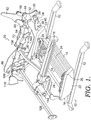
- a rocker-recliner base 10 is shown in an upright position in accordance with an embodiment of the invention.
- the rocker-recliner base 10 couples together a footrest, chair back, chair arms and a chair seat of a rocker chair. For the sake of clarity, these portions of the chair are not shown.
- the base 10 includes a pair of spaced apart base rails 12, typically made from tubular steel. The base rails support the remainder of the base 10 above the surface on which the chair is placed.
- Cross tubes 14 extend between and are affixed to the base rails 12, such as by welding.
- a rocker assembly 16 is coupled to the cross tubes.
- the rocker assembly 16 includes a lower spring retainer (not shown) coupled to the cross tubes 14, a pair of springs 18 secured on their lower ends to the lower spring retainer on each side of the base 10, and secured on their upper ends to an upper spring retainer 20.
- the upper spring retainer 20 is coupled to a rocker cam 22.
- Rocker cam 22 can be made from any of a number of materials, such as wood, metal or molded plastic.
- Cross rails 24 extend between the rocker cams and are coupled to the rocker cams. While the rocker base is described above, and shown in the Figures, many other configurations for a rocker assembly could be used in embodiments described below.
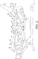
- a recline mechanism 26 is coupled to each side of the rocker base 10. Only one mechanism 26 is shown in the Figures, for clarity, with the removed side being a mirror-image of the side that is shown.
- the recline mechanism 26 is coupled to the rocker base through a base plate 28.
- the base plate 28 extends upward from the rocker base and extends forwardly and rearwardly of the rocker cam 22.
- the base plate 28, like the remainder of the links described below is typically made from steel.
- the upper, rearward end of base plate 28 is pivotably coupled to a rear pivot link 30 at pivot point 32.
- Rear pivot link 30 has a generally triangular shape, as shown. Rearwardly and below pivot point 32 (as viewed in FIGS.
- rear pivot link 30 is pivotably coupled to a wheel link 34 at pivot point 36.
- the outer end of wheel link 34 has a wheel 38 pivotably coupled to it.
- a wheel control link 40 is pivotably coupled to, and between, base plate 28 and wheel link 34.
- the wheel link 34 and wheel control link 40 operate as known in other existing mechanisms.
- the lower end of rear pivot link 30 is pivotably coupled to a footrest drive link 42 through a roller (not shown) that rides within a slot 44 on a sequence link 46.
- sequence link 46 is pivotably coupled to a rear lift link 48 at pivot point 50. Sequence link 46 thus extends between rear lift link 48 and rear pivot link 30, and is also coupled to footrest drive link 42.
- the rear lift link 48 is pivotably coupled on its rearward end to rear pivot link 30 at pivot point 52.
- the opposite end of rear lift link 48 is pivotably coupled to a connector link 54 and pivot point 56.
- the rear lift link 48 thus extends between, and is pivotably coupled to, the rear pivot link 30 and the connector link 54.
- the rear lift link 48 is also pivotally coupled to a seat mounting plate 86 at pivot point 57.
- the rear lift link 48 includes a rivot 59 that is slidably received in a slot 61 formed in the seat mounting plate 86.
- the rivot 59 serves as a stop within the slot 61 as the recline mechanism 26 opens.
- a rear back pivot link 58 is pivotably coupled to rear lift link 48 at pivot point 60.
- the opposite end of rear back pivot link 58 is pivotably coupled to back bracket 62 at pivot point 64.
- the back bracket 62 is shaped as shown, with an upper extending leg that is used to couple the back bracket 62 to a back of the chair.
- the forward, lower area of back bracket 62 is pivotably coupled to an upper end of a forward back pivot link 66 and pivot point 68.
- the lower end of forward back pivot link 66 is pivotably coupled to rear lift link 48 at pivot point 70.
- a rearward end of a control link 72 is pivotably coupled to the forward back pivot link 66 at pivot point 74.
- the forward end of control link 72 is pivotably coupled to a front lift link 76 at pivot point 78.
- the front lift link 76 is pivotably coupled on its rear end to the upper end of connector link 54 at pivot point 80.
- a forward end of front lift link 76 is pivotably coupled to the upper end of a front pivot link 82 at pivot point 84.
- front lift link 76 is also pivotably coupled to the seat mounting plate 86 at pivot point 88 (see FIG. 3 ).
- the lower end of front pivot link 82 is pivotably coupled to base plate 28 at pivot point 90.
- footrest drive link 42 extends from the connection to sequence link 46 and rear pivot link 30 forwardly and is pivotably connected on its forward end to a rear ottoman link 92 at pivot point 94.
- Rear ottoman link 92 is pivotably coupled on its upper end to seat mounting plate 86 at pivot point 96.
- the opposite end of rear ottoman link 92 is pivotably coupled to a footrest extension link 98 at pivot point 100 (see FIG. 6 ).
- the end of footrest extension link 98 opposite pivot point 100 is pivotably coupled to a mid-ottoman bracket 102 and pivot point 104.
- footrest extension link 98 is pivotably coupled, generally at a mid-point, to a front ottoman link 106 at pivot point 108.
- Front ottoman link 106 is pivotably coupled on one end to seat mounting plate 86 at pivot point 110 (see FIG. 5 ), and is pivotably coupled on the other end to a wide ottoman link 112 at pivot point 114.
- the wide ottoman link 112 is pivotably coupled on its other end to an ottoman bracket 116 at pivot point 118.
- a mid-point of the mid-ottoman bracket 102 is pivotably coupled to the wide ottoman link 112 at pivot point 120.
- a footrest control link 122 is pivotably coupled on one end to ottoman bracket 116 at pivot point 124, and is pivotably coupled on the other end to mid-ottoman bracket 102 at pivot point 126.
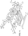
- the ottoman linkage described above can be moved from a closed position in FIGS. 1-3 , to an extended position as shown in FIGS. 4-9 .
- the recline mechanism 26 described above can be implemented as a motorized or a manual version, depending on the desired end use.
- a motorized version as best seen in FIGS. 1 , 4 and 7 , a motor tube 128 is secured to, and between, rear ottoman links 92. More specifically, a motor tube bracket 130 is pivotably secured to the rear ottoman link 92 at pivot point 132. On the opposite end of motor tube bracket 130, an end cap 134 is fixedly coupled to the motor tube bracket 130. The end caps 134 are coupled to the motor tube 128, such as by welding.
- a control link 136 is pivotably coupled to the motor tube bracket 130 at pivot point 138, and pivotably coupled to the front ottoman link 106 at pivot point 140.
- a clevis 142 is fixedly coupled to motor tube 128 midway along motor tube 128, facilitating a pivotable coupling to one end of a motor 144.
- Motor 144 is also coupled to recline mechanism 26 through a drive block 146 which moves along a track 148 in relation to the motor body 150.
- a rear motor tube 152 is pivotably coupled to drive block 146 at pivot point 154 located below the track 148.
- the rear motor tube 152 is fixedly coupled on its opposite end to a motor bell crank 156.
- the motor bell crank 156 is pivotably coupled to control link 72 at pivot point 158.
- motor bell crank 156 is pivotably coupled to seat mounting plate 86 through a strut 160 via pivot points 162 and 164. The motor bell crank 156 is thus connected between the seat mounting plate 86 and the front lift link 76 through the control link 72 and the strut 160.
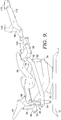
- Recline mechanism 26 moves between the closed position of FIGS. 1-3 , to the TV position of FIGS. 4-6 , to the full-recline position of FIGS. 7-9 .
- the arrangement of recline mechanism 26 provides a projected pivot point for the chair back that is close to the point at which the bottom of a chair back and the back of a seat cushion meet, when in a finished chair. In styling a finished chair, the manufacturer can design the chair back and seat such that they meet as close to this projected pivot point as possible.
- the back bracket 62 pivotably coupled to rear back pivot link 58 and forward back pivot link 66, moved through control link 72 by the rear pivot link 30, rear lift link 48 and front lift link 76 allow the true pivot point of back bracket 62 (in relation to the seat mounting plate 86) to be projected forwardly, and above, the actual pivotable connection of back bracket 62.
- connection of the motor 144 as described above allows the motor to extend and retract, while staying in a lower position as compared to traditional motorized rocker recliner mechanisms.
- the motor 144 is coupled to the rear ottoman link 92 rather than the front ottoman link 106.
- This connection, along with the control link 136, and the bent rear motor tubes 152 allow the motor to travel in a less arcuate path in operation, and to stay lower throughout its actuation.
- the recline mechanism 26 also uses more motor stroke to extend the seat to the full-recline position, so the transition from the TV position to the full-recline position is achieved in a slow, controlled manner that is comfortable to the user.
- FIGS. 10-15 illustrate a similar recline mechanism in use on a motorized glider, as opposed to a rocker base. Due to the novel recline mechanism, much of the same linkage can be used on a glider base as was described above for the rocker base 10.
- the glider base 200 spaced apart base rails 202 are coupled to one another through cross bars 204.
- the cross bars 204 may comprise tubular steel or steel angle iron.
- a glide bracket 206 is fixedly coupled to a corresponding base rail 202.
- a front glide link 208 is pivotably coupled to the glide bracket 206 at pivot point 210, and a rear glide link 212 is pivotably coupled to the glide bracket 206 at pivot point 214.
- the glider base 200 is coupled to a recline mechanism 216 through a base plate 218. More specifically, the lower end of front guide link 208 and the lower end of rear guide link 212 are pivotably coupled to base plate 218 at pivot points 220 and 222, respectively. Base plate 218 thus reciprocates, or glides, with respect to glider base 200 on front and rear glide links 208, 212.
- a rear link 224 is pivotably coupled to the rear end of base plate 218 at pivot point 226. The upper end of rear link 224 is pivotably coupled to rear pivot link 30.
- Blocker control link 228 is pivotably coupled to footrest drive link 42 at pivot point 230.
- the opposite end of blocker control link 228 is pivotably coupled to a hook link 232 at pivot point 234.
- Hook link 232 has an L-shape, with a hook slot 236 generally mid-way along the link. The slot 236 engages a stop pin 238 to prevent gliding motion when in the TV or full-recline positions.
- the end of hook link 232 opposite pivot point 234 is pivotably coupled to base plate 218 at pivot point 240.
- a front blocker control link 242 is pivotably coupled to footrest drive link 42 at pivot point 244.
- front blocker control link 242 is pivotably coupled to a front blocker link 246 at pivot point 248.
- the front blocker link 246 has a wheel 250 that abuts the front glide link 208 when in the TV or full-recline position.
- the remainder of the recline mechanism 216 is the same as the recline mechanism 26 described above, and so it will not be described further here.
- the links and pivot points are labeled in the Figures with the same numbers as used above with respect to FIGS. 1-9 .
- the glider of FIGS. 10-15 has the same projected back pivot point, and low motor mount features as described above for the rocker of FIGS. 1-9 .
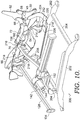
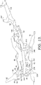
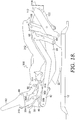
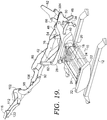
- FIGS. 16-24 illustrate an example of an alternate mechanism 300, shown on a rocker base 10 constructed as described above with respect to FIGS. 1-9 . Much of the mechanism 300 shares links common to those described above with respect to recline mechanism 26. The links common to mechanism 300 are labeled with the same reference numbers. Mechanism 300 is shown on a manual rocker, without any motor. Mechanism 300 could, of course, be motorized. In the example of FIGS. 16-24 , control link 72 is replaced with control link 302, as best seen in FIG. 18 . To accommodate control link 302, rear back pivot link 304 is longer than rear back pivot link 58 of FIGS. 1-15 .
- Rear back pivot link 304 is pivotably coupled to control link 302 at pivot point 306, to rear lift link 48 at pivot point 308, and to back bracket 62 at pivot point 310.
- a slightly varied seat mounting plate 312 is used in this example.
- Seat mounting plate 312 has a downwardly extending tab 314 that is used to pivotably couple the end of control link 302 opposite pivot point 306, at pivot point 316.
- control link 302 moves back bracket 62, guided by forward back pivot link 66 and rear back pivot link 304.
- the mechanism 300 provides an alternate construction for projecting the back pivot point, so that the back pivots with respect to the seat in a manner similar to that described above with respect to FIGS. 1-15 .
- Such an arrangement could also be implemented on a glider base, with similar modifications made as described above with respect to FIGS. 10-15 , but using the alternative control link 302 (and the connection of the control link 302) as described in FIGS. 16-24 .
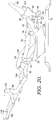
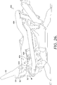
- Figures 25 and 26 illustrate another alternative embodiment of a mechanism 400 according to the invention, shown on a glider base 200 constructed as described above with respect to FIGS. 10-15 . Much of the mechanism 400 shares links common to those described above with respect to the recline mechanism 26. The links common to mechanism 400 are labeled with the same reference numbers.
- Mechanism 400 is shown on a motorized glider. Mechanism 400 could, of course, be constructed as a manual glider.
- the forward back pivot link 66 is replaced with forward back pivot link 402.
- the seat mounting plate 86 has been replaced with seat mounting plate 404.
- the seat mounting plate 404 includes a tab 406 that extends below a flange of the seat mounting plate 404, as best seen in FIG. 26 .
- the forward back pivot link 402 connects directly to the seat mounting plate 404 at pivot point 408, as opposed to connecting to the rear lift link 48 at pivot point 70 as discussed above in reference to the recline mechanism 26.
- the forward back pivot 402 link may include an offset that allows the forward back pivot 402 to avoid the rear lift link 48 as the mechanism 400 moves.
- the mechanism 400 provides an alternate construction for projecting the back pivot point, so that the back pivots with respect to the seat in a manner similar to that described above with respect to FIGS. 1-15 .
- Such an arrangement could also be implemented on a rocker base, with similar modifications as described above with respect to FIGS. 1-9 , but using the alternative control link 302 (and the connection of the control link 302) as described in reference to FIGS. 16-24 .
- FIGS. 1 - 15 , and 25 , 26 Some aspects of this disclosure have been described with respect to the illustrative embodiments provided by FIGS. 1 - 15 , and 25 , 26 as well as other examples provided by FIGS. 16 24 . Additional aspects and further developments of the invention as well as other examples of the disclosure will now be described that may related subject matter included in one or more claims of this application, or one or more related applications, but the claims are not limited to only the subject matter described in the below portions of this description. These additional aspects may include features illustrated by FIGS. 1 - 26 , features not illustrated by FIGS. 1 - 26 , and any combination thereof. When describing these additional aspects, reference may or may not be made to elements depicted by FIGS. 1 - 26 .
- the linkage includes a back bracket and a rear lift link positioned below the back bracket.
- the linkage also includes a forward back pivot link pivotally coupled to the back bracket at a first pivot point and pivotally coupled at a second pivot point to one of a seat mounting plate and the rear lift link.
- the linkage also includes a rear back pivot link pivotally coupled to the back bracket at a third pivot point and pivotally coupled to the rear lift link at a fourth pivot point.
- the third pivot point is rearward of the first pivot point and the fourth pivot point is rearward of the second pivot point.
- the linkage alsos include a control link having a first end opposite a second end. The first end is pivotally coupled to the forward back pivot link at a fifth pivot point. The second end is pivotally coupled to a front lift link.
- the fifth pivot point is intermediate to the first pivot point and the third pivot point.
- the linkage is configured to move between a closed position and a fully reclined position. Further, the linkage may be configured to stop at one or more intermediate points between the closed position and the fully reclined position.
- the back bracket Upon movement of the linkage from the closed position to the fully reclined position, the back bracket rotates around a projected pivot point.
- the projected pivot point is forward and above the first pivot point when the linkage is in the closed position.
- the projected pivot point may be rearward and above the first pivot point when the linkage is in the fully reclined position.
- the forward back pivot link may rotate about the third pivot point and the first pivot point may move forwardly and upwardly.
- the control link may include a mounting tab proximate the second end.
- a motor may be coupled to the mounting tab and configured to move the linkage between a closed position and a fully reclined position.
- the linkage may further include a base, a rocker cam coupled to the base and a base plate coupled to the rocker cam.
- a front pivot link may be pivotally coupled to the base plate proximate a first end of the base plate.
- a rear pivot link may be pivotally coupled to the base plate proximate a second end of the base plate, the first end being spaced apart from the second end.
- the rear pivot link may be pivotally coupled to the rear lift link and the front pivot link may be pivotally coupled to the front lift link.
- the linkage may further include a glider base and a base plate coupled to the glider base.
- the front lift link may be pivotally coupled to the base plate proximate a first end of the base plate.
- a rear pivot link may be pivotally coupled to the base plate proximate a second end of the base plate, the first end being spaced apart from the second end.
- the rear pivot link may be pivotally coupled to the rear lift link.
- the linkage may include a back bracket, a seat mounting plate, a rear lift link, a forward back pivot link, a rear back pivot link, and a control link.
- the forward back pivot link may be pivotally coupled to the back bracket at a first pivot point and pivotally coupled to the seat mounting plate at a second pivot point.
- the rear back pivot link may be pivotally coupled to the back bracket at a third pivot point and pivotally coupled to the rear lift link at a fourth pivot point.
- the third pivot point may be rearward of the first ivot point and the fourth pivot point may be rearward of the second pivot point.
- the control link may have a first end opposite a second end. The first end may be pivotally coupled to the rear back pivot link at a fifth pivot point. The second end may be pivotally coupled to the seat mounting plate.
- the fourth pivot point may be intermediate to the second pivot point and the fifth pivot point.
- the rear back pivot link has a first end opposite a second end.
- the second pivot point may be positioned proximate the first end of the rear back pivot link.
- the fifth pivot point may be positioned proximate the second end of the rear back pivot link.
- the second end of the control link may be pivotally coupled to a tab extending from the seat mounting plate.
- the motor-driven seating unit may include a first linkage coupled to a first side of a base unit and a second linkage coupled to a second side of the base unit opposite the first side.
- the first and second linkages may be configured to move between a closed position where an ottoman portion is folded and an open position where the ottoman portion is unfolded.
- a cross-tube may be coupled on a first end to the ottoman portion of the first linkage at a first rear ottoman link.
- the cross-tube may be coupled on a second end to the ottoman portion of the second linkage at a second rear ottoman link.
- a motor may be coupled to the cross-tube and configured to move the first and second linkages between the closed position and the open position.
- a first bracket may be coupled to the first rear ottoman link at a first pivot point.
- the first end of the cross-tube may be fixedly coupled to the first bracket.
- a first ottoman control link may be pivotally coupled to the first bracket between the first pivot point and the fixed coupling.
- the first ottoman control link may be pivotally coupled to a first front ottoman link of the ottoman portion of the first linkage.
- a second bracket may be coupled to the second rear ottoman link at a second pivot point.
- the second end of the cross-tube may be fixedly coupled to the second bracket.
- a second ottoman control link may be pivotally coupled to the second bracket between the second pivot point and the fixed coupling.
- the second ottoman control link may be pivotally coupled to a second front ottoman link of the ottoman portion of the second linkage.
- a clevis may be fixedly coupled to the cross-tube and the motor may be pivotally coupled to the clevis.
- the motor includes a track and a drive block that is configured to move along the track as the first and second linkages move between the closed position and the open position.
- a first motor bell crank may be pivotally coupled to a first control link of the first linkage and a second motor bell crank may be pivotally coupled to a second control link of the second linkage.
- a rear motor tube having a third end opposite a fourth end may extend between the first and second linkages. The rear motor tube may be fixedly coupled on the third end to the first motor bell crank and fixedly coupled on the fourth end to the second motor bell crank.
- the rear motor tube may be pivotally coupled to the drive block.
- the first motor bell crank may be pivotally connected to a first seat mounting plate of the first linkage.
- the second motor bell crank may be pivotally connected to a second seat mounting plate of the second linkage.
- the motor-driven seating unit may comprise one of a rocker seating unit or a glider seating unit.
Landscapes
- Health & Medical Sciences (AREA)
- Dentistry (AREA)
- General Health & Medical Sciences (AREA)
- Chairs For Special Purposes, Such As Reclining Chairs (AREA)
Claims (6)
- Verbindung zur Verwendung in Liegemöbeln, aufweisend:eine Lehnenhalterung (62);ein hinteres Hebeglied (48), das unterhalb der Lehnenhalterung (62) angeordnet ist;ein vorderes Lehnenschwenkglied (66; 402), das schwenkbar mit der Lehnenhalterung (62) an einem ersten Drehpunkt (68) und schwenkbar an einem zweiten Drehpunkt (70; 408) mit einer Sitzbefestigungsplatte (404) und dem hinteren Hebeglied (48) gekoppelt ist;ein hinteres Lehnenschwenkglied (58), das schwenkbar mit der Lehnenhalterung (62) an einem dritten Drehpunkt (64) und schwenkbar mit dem hinteren Hebeglied (48) an einem vierten Drehpunkt (60) gekoppelt ist, wobei der dritte Drehpunkt (64) hinterhalb vom ersten Drehpunkt (68) liegt und der vierte Drehpunkt (60) hinterhalb vom zweiten Drehpunkt (70; 408) liegt; undein Steuerungsglied (72) mit einem ersten Ende gegenüber einem zweiten Ende, wobei das erste Ende schwenkbar mit dem vorderen Lehnenschwenkglied (66; 402) an einem fünften Drehpunkt (74) gekoppelt ist, und das zweite Ende schwenkbar mit einem vorderen Hebeglied (76) gekoppelt ist, wobei der fünfte Drehpunkt (74) zwischen dem ersten Drehpunkt (68) und dem dritten Drehpunkt (64) angeordnet ist;wobei die Verbindung konfiguriert ist, sich zwischen einer geschlossenen Position und einer vollständig zurückgelehnten Position zu bewegen; undwobei sich die Lehnenhalterung (62) bei der Bewegung der Verbindung aus der geschlossenen Position in die vollständig zurückgelehnte Position um einen projizierten Drehpunkt dreht,dadurch gekennzeichnet, dassder projizierte Drehpunkt vorderhalb und oberhalb des ersten Drehpunktes (68) liegt, wenn sich die Verbindung in der geschlossenen Position befindet.
- Verbindung gemäß Anspruch 1, wobei der projizierte Drehpunkt hinterhalb und oberhalb des ersten Drehpunktes (68) liegt, wenn sich die Verbindung in der vollständig zurückgelehnten Position befindet.
- Verbindung gemäß einem der Ansprüche 1-2, wobei bei Bewegung der Verbindung aus der geschlossenen Position in die vollständig zurückgelehnte Position sich das vordere Lehnenschwenkglied (66; 402) um den dritten Drehpunkt (64) dreht und sich der erste Drehpunkt (68) vorwärts und aufwärts bewegt.
- Verbindung gemäß einem der Ansprüche 1-3, wobei das Steuerungsglied (72) eine Befestigungslasche in der Nähe des zweiten Endes aufweist, wobei ein Motor mit der Befestigungslasche gekoppelt ist und konfiguriert ist, die Verbindung zwischen einer geschlossenen Position und einer vollständig zurückgelehnten Position zu bewegen.
- Verbindung gemäß einem der Ansprüche 1-4, weiterhin aufweisend:eine Basis (10);einen Kippnocken (22), der mit der Basis (10) gekoppelt ist;eine Basisplatte (28), die mit dem Kippnocken (22) gekoppelt ist;ein vorderes Schwenkglied (82), das schwenkbar mit der Basisplatte (28) in der Nähe eines ersten Endes der Basisplatte gekoppelt ist;ein hinteres Schwenkglied (30), das schwenkbar mit der Basisplatte (28) in der Nähe eines zweiten Endes der Basisplatte gekoppelt ist, wobei das erste Ende von dem zweiten Ende beabstandet ist;wobei:das hintere Schwenkglied (30) schwenkbar mit dem hinteren Hebeglied (48) gekoppelt ist; unddas vordere Schwenkglied (28) schwenkbar mit dem vorderen Hebeglied (76) gekoppelt ist.
- Verbindung gemäß einem der Ansprüche 1-5, weiterhin aufweisend:eine Gleitbasis (200);eine Basisplatte (218), die mit der Gleitbasis (200) gekoppelt ist, wobei das vordere Hebeglied (76) schwenkbar mit der Basisplatte (218) in der Nähe eines ersten Endes der Basisplatte gekoppelt ist;ein hinteres Schwenkglied (30), das schwenkbar mit der Basisplatte (218) in der Nähe eines zweiten Endes der Basisplatte (218) gekoppelt ist, wobei das erste Ende vom zweiten Ende beabstandet ist und das hintere Schwenkglied (30) schwenkbar mit dem hinteren Hebeglied (48) gekoppelt ist.
Priority Applications (2)
| Application Number | Priority Date | Filing Date | Title |
|---|---|---|---|
| EP19186712.6A EP3571960A1 (de) | 2016-07-29 | 2017-07-27 | Motorisch angetriebene sitzeinheit |
| PL17183598T PL3275341T3 (pl) | 2016-07-29 | 2017-07-27 | Mechanizm łączący rozkładanego fotela bujanego/pływającego z wysuniętym punktem obrotu oparcia |
Applications Claiming Priority (2)
| Application Number | Priority Date | Filing Date | Title |
|---|---|---|---|
| US201662368283P | 2016-07-29 | 2016-07-29 | |
| US15/657,454 US10653243B2 (en) | 2016-07-29 | 2017-07-24 | Rocker/glider recline linkage with projected back pivot point |
Related Child Applications (2)
| Application Number | Title | Priority Date | Filing Date |
|---|---|---|---|
| EP19186712.6A Division EP3571960A1 (de) | 2016-07-29 | 2017-07-27 | Motorisch angetriebene sitzeinheit |
| EP19186712.6A Division-Into EP3571960A1 (de) | 2016-07-29 | 2017-07-27 | Motorisch angetriebene sitzeinheit |
Publications (3)
| Publication Number | Publication Date |
|---|---|
| EP3275341A2 EP3275341A2 (de) | 2018-01-31 |
| EP3275341A3 EP3275341A3 (de) | 2018-03-21 |
| EP3275341B1 true EP3275341B1 (de) | 2019-08-28 |
Family
ID=59416615
Family Applications (2)
| Application Number | Title | Priority Date | Filing Date |
|---|---|---|---|
| EP17183598.6A Active EP3275341B1 (de) | 2016-07-29 | 2017-07-27 | Schaukel- und lehnstuhlrückenlehnenverbindung mit projiziertem lehnendrehpunkt |
| EP19186712.6A Withdrawn EP3571960A1 (de) | 2016-07-29 | 2017-07-27 | Motorisch angetriebene sitzeinheit |
Family Applications After (1)
| Application Number | Title | Priority Date | Filing Date |
|---|---|---|---|
| EP19186712.6A Withdrawn EP3571960A1 (de) | 2016-07-29 | 2017-07-27 | Motorisch angetriebene sitzeinheit |
Country Status (5)
| Country | Link |
|---|---|
| US (1) | US10653243B2 (de) |
| EP (2) | EP3275341B1 (de) |
| CN (1) | CN107660913B (de) |
| CA (1) | CA2974705C (de) |
| PL (1) | PL3275341T3 (de) |
Families Citing this family (14)
| Publication number | Priority date | Publication date | Assignee | Title |
|---|---|---|---|---|
| US10299597B1 (en) * | 2018-02-13 | 2019-05-28 | L&P Property Management Company | High-leg hidden ottoman recliner seating mechanism |
| CN108402767B (zh) * | 2018-04-28 | 2023-08-29 | 浙江飞力科技有限公司 | 一种活动沙发的头靠腰枕联动装置 |
| US10932570B2 (en) * | 2019-05-20 | 2021-03-02 | L&P Property Management Company | Zero-wall clearance linkage mechanism with power seat drive |
| US10842274B1 (en) * | 2019-05-20 | 2020-11-24 | L&P Property Management Company | Zero-wall clearance linkage mechanism with power seat drive |
| CN113679194A (zh) * | 2020-05-18 | 2021-11-23 | L & P 产权管理公司 | 具有突出的靠背枢轴的摇椅/滑椅倾斜联动装置 |
| US11528993B2 (en) | 2020-06-15 | 2022-12-20 | L&P Property Management Company | Rocker reclining mechanism for a rocker recliner rocking between the arms |
| US11229290B1 (en) * | 2020-07-20 | 2022-01-25 | Leggett & Platt, Inc. | Pedestal glider and recliner chair and mechanism |
| US11178970B1 (en) * | 2020-09-29 | 2021-11-23 | L&P Property Management Company | High-leg hidden ottoman recliner seating mechanism |
| CN113509017B (zh) * | 2021-06-10 | 2023-11-07 | 锐迈机械科技(吴江)有限公司 | 用于可活动的座椅单元的机械伸展装置及座椅单元 |
| CN113142861B (zh) * | 2021-05-17 | 2023-10-27 | 锐迈机械科技(吴江)有限公司 | 用于可活动的座椅单元的机械伸展装置及座椅单元 |
| US11992125B2 (en) * | 2021-06-18 | 2024-05-28 | Ultra-Mek, Inc. | Reclining seating unit with reciprocating capability |
| US20230292922A1 (en) * | 2022-03-18 | 2023-09-21 | La-Z-Boy Incorporated | Reclining chaise mechanism |
| US11903485B1 (en) * | 2022-10-12 | 2024-02-20 | L&P Property Management Company | Lift chair mechanism with zero-gravity position options |
| US20240335042A1 (en) * | 2023-04-09 | 2024-10-10 | Motomotion China Corporation | Powered rocking lounger chair |
Family Cites Families (46)
| Publication number | Priority date | Publication date | Assignee | Title |
|---|---|---|---|---|
| FR1255403A (fr) | 1960-01-25 | 1961-03-10 | Fauteuil transformable | |
| JPS506825B1 (de) | 1971-01-21 | 1975-03-18 | ||
| US4071275A (en) * | 1976-03-22 | 1978-01-31 | Royal Development Company, Inc. | Recliner chair with wall avoiding action |
| US4194783A (en) | 1977-03-28 | 1980-03-25 | Mohasco Corporation | Wall proximity chairs and hardware therefor |
| US4108491A (en) | 1977-04-22 | 1978-08-22 | Royal Development Company, Inc. | Wall-avoiding recliner chair |
| US4591205A (en) | 1983-11-04 | 1986-05-27 | Leggett & Platt, Incorporated | Glider recliner |
| US4904017A (en) | 1985-02-26 | 1990-02-27 | Monon Corporation | Trailer construction |
| US5072988A (en) | 1987-06-09 | 1991-12-17 | Super Sagless Corporation | Wall proximity chair |
| US4815788A (en) | 1987-06-25 | 1989-03-28 | Super Sagless Corp. | Three-way incliner |
| CN2233696Y (zh) * | 1995-08-10 | 1996-08-28 | 徐灯铨 | 躺椅的起身辅助装置 |
| US5795021A (en) | 1995-10-10 | 1998-08-18 | Rogers; W. Clark | Gliding reclining chair |
| CA2234842C (en) | 1995-10-18 | 2002-10-01 | La-Z-Boy Incorporated | Glider chair |
| US5772278A (en) | 1996-09-30 | 1998-06-30 | Hickory Springs Manufacturing Company | Recliner chair having wall-avoiding linkage arrangement |
| US6637813B2 (en) | 1999-04-23 | 2003-10-28 | L&P Property Management Company | Reclining mechanism and furniture item having pusher mechanism |
| US7494185B2 (en) * | 2004-08-26 | 2009-02-24 | L & P Property Management Company | J-back adjustment mechanism |
| US7396074B2 (en) | 2006-06-08 | 2008-07-08 | L & P Property Management Company | Linkage mechanism for a recliner chair |
| US7850232B2 (en) | 2007-03-09 | 2010-12-14 | Ashley Furniture Industries, Inc. | Zero clearance recliner mechanism |
| US8016348B2 (en) | 2008-11-24 | 2011-09-13 | Ultra-Mek, Inc. | Reciprocating seating unit with power actuator |
| MX337829B (es) * | 2010-01-15 | 2016-03-22 | L & P Property Management Co | Mecanismos de eslabon de sillon reclinable mecedor energizado. |
| US8398165B2 (en) | 2010-01-15 | 2013-03-19 | L & P Property Management Company | Powered rocker recliner linkage mechanism |
| US8308228B2 (en) | 2010-02-11 | 2012-11-13 | L & P Property Management Company | Zero-wall clearance linkage mechanism for a lifting recliner |
| US8449027B2 (en) * | 2010-03-23 | 2013-05-28 | L & P Property Management Company | Full-flat recline linkage |
| US8398169B2 (en) | 2010-04-13 | 2013-03-19 | La-Z-Boy Incorporated | Furniture member having powered gliding motion |
| US8833844B2 (en) | 2010-04-13 | 2014-09-16 | La-Z-Boy Incorporated | Power actuated glider furniture member |
| US8573687B2 (en) | 2010-08-27 | 2013-11-05 | L & P Property Management Company | Zero-wall clearance linkage mechanism for providing additional layout |
| US8616627B2 (en) | 2010-11-08 | 2013-12-31 | Ultra-Mek, Inc. | Gliding-reclining seating unit |
| US8517463B2 (en) | 2010-11-09 | 2013-08-27 | Ultra-Mek, Inc. | Gliding-reclining layflat seating unit with power actuator and manual and automatic locking linkages |
| US8915544B2 (en) | 2011-08-26 | 2014-12-23 | La-Z-Boy Incorporated | Furniture member with mechanism for powered occupant lift |
| ITRM20110166U1 (it) * | 2011-10-26 | 2013-04-27 | Natuzzi Spa | Struttura di dispositivo per la movimentazione di componenti di appoggio di un divano, una poltrona o simili |
| US8985694B2 (en) | 2011-12-28 | 2015-03-24 | Kintec-Solution Gmbh | Item of seating furniture and fitting therefor |
| US8944498B2 (en) * | 2012-01-05 | 2015-02-03 | L & Property Management Company | Linkage mechanism for a dual-motor lifting recliner |
| US9149121B2 (en) | 2012-02-06 | 2015-10-06 | Ultra-Mek, Inc. | Gliding-reclining seating unit actuated by pushing on the arms |
| CN102894699B (zh) | 2012-11-01 | 2015-05-20 | 锐迈机械科技(吴江)有限公司 | 一种活动座椅靠背随动装置 |
| WO2014139179A1 (en) | 2013-03-15 | 2014-09-18 | Shanghai Industries Group | Recliner chair with moving backrest pivot linkage |
| PL2801293T3 (pl) | 2013-05-10 | 2016-06-30 | Kintec Solution Gmbh | Mebel do siedzenia i okucie do niego |
| US10278510B2 (en) | 2013-05-10 | 2019-05-07 | L&P Property Management Company | Linkage mechanism for hi-leg seating unit |
| US9844269B2 (en) | 2013-05-10 | 2017-12-19 | L&P Property Management Company | Motorized linkage mechanism for hi-leg seating unit |
| MX2016005600A (es) * | 2013-10-28 | 2016-08-11 | L & P Property Management Co | Mecanismo de acoplamiento con cero distancia hacia la pared para proporcionar una configuracion adicional. |
| WO2015148484A1 (en) | 2014-03-24 | 2015-10-01 | L & P Property Management Company | Zero-wall clearance linkage mechanism including a single drive link |
| US9468295B2 (en) | 2014-04-04 | 2016-10-18 | L & P Property Management Company | Zero-wall clearance linkage mechanism for a dual motor lifting recliner |
| CN103932521B (zh) | 2014-05-14 | 2017-01-11 | 锐迈机械科技(吴江)有限公司 | 一种活动沙发电动机械伸展装置 |
| US10021980B2 (en) | 2014-07-22 | 2018-07-17 | L&P Property Management Company | Zero-wall clearance linkage mechanism with power seat drive |
| CN204158028U (zh) | 2014-09-09 | 2015-02-18 | 黄小卫 | 一种活动沙发电动机械伸展装置 |
| US9603452B2 (en) | 2014-10-14 | 2017-03-28 | Ultra-Mek, Inc. | Gliding-reclining seating unit with power actuators |
| US9962004B2 (en) * | 2014-10-16 | 2018-05-08 | L&P Property Management Company | Profile ottoman linkage |
| US9845852B2 (en) | 2015-03-20 | 2017-12-19 | L&P Property Management Company | Motorized positioning apparatus for a seating unit |
-
2017
- 2017-07-24 US US15/657,454 patent/US10653243B2/en active Active
- 2017-07-27 EP EP17183598.6A patent/EP3275341B1/de active Active
- 2017-07-27 EP EP19186712.6A patent/EP3571960A1/de not_active Withdrawn
- 2017-07-27 CA CA2974705A patent/CA2974705C/en active Active
- 2017-07-27 PL PL17183598T patent/PL3275341T3/pl unknown
- 2017-07-31 CN CN201710638416.XA patent/CN107660913B/zh active Active
Non-Patent Citations (1)
| Title |
|---|
| None * |
Also Published As
| Publication number | Publication date |
|---|---|
| CN107660913B (zh) | 2021-11-05 |
| US10653243B2 (en) | 2020-05-19 |
| EP3571960A1 (de) | 2019-11-27 |
| PL3275341T3 (pl) | 2020-02-28 |
| CA2974705C (en) | 2021-02-16 |
| CN107660913A (zh) | 2018-02-06 |
| CA2974705A1 (en) | 2018-01-29 |
| US20180027967A1 (en) | 2018-02-01 |
| EP3275341A2 (de) | 2018-01-31 |
| EP3275341A3 (de) | 2018-03-21 |
Similar Documents
| Publication | Publication Date | Title |
|---|---|---|
| EP3275341B1 (de) | Schaukel- und lehnstuhlrückenlehnenverbindung mit projiziertem lehnendrehpunkt | |
| US20200275781A1 (en) | Rocker/Glider Recliner Linkage With Projected Back Pivot Point | |
| US10420422B2 (en) | Recliner chair having improved wall clearance and recline linkage with projected back pivot point | |
| EP2878229B1 (de) | Verbindungsmechanismen für angetriebenen Schaukel- und Lehnstuhl | |
| EP1173083B1 (de) | Fussstütze und möbelstück | |
| US11730268B2 (en) | Rocker reclining mechanism for a rocker recliner rocking between the arms | |
| WO2016061317A1 (en) | Profile ottoman linkage | |
| US11766124B2 (en) | Slim-profile, all-linkage, wall-proximity reclining mechanism allowing a wood-to-floor recliner seating unit | |
| CN113679194A (zh) | 具有突出的靠背枢轴的摇椅/滑椅倾斜联动装置 | |
| US20240315452A1 (en) | High-leg recliner seating mechanism |
Legal Events
| Date | Code | Title | Description |
|---|---|---|---|
| PUAI | Public reference made under article 153(3) epc to a published international application that has entered the european phase |
Free format text: ORIGINAL CODE: 0009012 |
|
| STAA | Information on the status of an ep patent application or granted ep patent |
Free format text: STATUS: THE APPLICATION HAS BEEN PUBLISHED |
|
| AK | Designated contracting states |
Kind code of ref document: A2 Designated state(s): AL AT BE BG CH CY CZ DE DK EE ES FI FR GB GR HR HU IE IS IT LI LT LU LV MC MK MT NL NO PL PT RO RS SE SI SK SM TR |
|
| AX | Request for extension of the european patent |
Extension state: BA ME |
|
| REG | Reference to a national code |
Ref country code: DE Ref legal event code: R079 Ref document number: 602017006480 Country of ref document: DE Free format text: PREVIOUS MAIN CLASS: A47C0001034000 Ipc: A47C0001035500 |
|
| PUAL | Search report despatched |
Free format text: ORIGINAL CODE: 0009013 |
|
| AK | Designated contracting states |
Kind code of ref document: A3 Designated state(s): AL AT BE BG CH CY CZ DE DK EE ES FI FR GB GR HR HU IE IS IT LI LT LU LV MC MK MT NL NO PL PT RO RS SE SI SK SM TR |
|
| AX | Request for extension of the european patent |
Extension state: BA ME |
|
| RIC1 | Information provided on ipc code assigned before grant |
Ipc: A47C 1/0355 20130101AFI20180213BHEP Ipc: A47C 1/032 20060101ALI20180213BHEP Ipc: A47C 1/035 20060101ALI20180213BHEP |
|
| STAA | Information on the status of an ep patent application or granted ep patent |
Free format text: STATUS: REQUEST FOR EXAMINATION WAS MADE |
|
| STAA | Information on the status of an ep patent application or granted ep patent |
Free format text: STATUS: EXAMINATION IS IN PROGRESS |
|
| 17P | Request for examination filed |
Effective date: 20180919 |
|
| RBV | Designated contracting states (corrected) |
Designated state(s): AL AT BE BG CH CY CZ DE DK EE ES FI FR GB GR HR HU IE IS IT LI LT LU LV MC MK MT NL NO PL PT RO RS SE SI SK SM TR |
|
| 17Q | First examination report despatched |
Effective date: 20181018 |
|
| GRAP | Despatch of communication of intention to grant a patent |
Free format text: ORIGINAL CODE: EPIDOSNIGR1 |
|
| STAA | Information on the status of an ep patent application or granted ep patent |
Free format text: STATUS: GRANT OF PATENT IS INTENDED |
|
| INTG | Intention to grant announced |
Effective date: 20190425 |
|
| GRAS | Grant fee paid |
Free format text: ORIGINAL CODE: EPIDOSNIGR3 |
|
| GRAA | (expected) grant |
Free format text: ORIGINAL CODE: 0009210 |
|
| STAA | Information on the status of an ep patent application or granted ep patent |
Free format text: STATUS: THE PATENT HAS BEEN GRANTED |
|
| AK | Designated contracting states |
Kind code of ref document: B1 Designated state(s): AL AT BE BG CH CY CZ DE DK EE ES FI FR GB GR HR HU IE IS IT LI LT LU LV MC MK MT NL NO PL PT RO RS SE SI SK SM TR |
|
| REG | Reference to a national code |
Ref country code: GB Ref legal event code: FG4D |
|
| REG | Reference to a national code |
Ref country code: CH Ref legal event code: EP |
|
| REG | Reference to a national code |
Ref country code: DE Ref legal event code: R096 Ref document number: 602017006480 Country of ref document: DE |
|
| REG | Reference to a national code |
Ref country code: AT Ref legal event code: REF Ref document number: 1171324 Country of ref document: AT Kind code of ref document: T Effective date: 20190915 |
|
| REG | Reference to a national code |
Ref country code: IE Ref legal event code: FG4D |
|
| REG | Reference to a national code |
Ref country code: NL Ref legal event code: MP Effective date: 20190828 |
|
| REG | Reference to a national code |
Ref country code: LT Ref legal event code: MG4D |
|
| PG25 | Lapsed in a contracting state [announced via postgrant information from national office to epo] |
Ref country code: PT Free format text: LAPSE BECAUSE OF FAILURE TO SUBMIT A TRANSLATION OF THE DESCRIPTION OR TO PAY THE FEE WITHIN THE PRESCRIBED TIME-LIMIT Effective date: 20191230 Ref country code: HR Free format text: LAPSE BECAUSE OF FAILURE TO SUBMIT A TRANSLATION OF THE DESCRIPTION OR TO PAY THE FEE WITHIN THE PRESCRIBED TIME-LIMIT Effective date: 20190828 Ref country code: BG Free format text: LAPSE BECAUSE OF FAILURE TO SUBMIT A TRANSLATION OF THE DESCRIPTION OR TO PAY THE FEE WITHIN THE PRESCRIBED TIME-LIMIT Effective date: 20191128 Ref country code: NL Free format text: LAPSE BECAUSE OF FAILURE TO SUBMIT A TRANSLATION OF THE DESCRIPTION OR TO PAY THE FEE WITHIN THE PRESCRIBED TIME-LIMIT Effective date: 20190828 Ref country code: LT Free format text: LAPSE BECAUSE OF FAILURE TO SUBMIT A TRANSLATION OF THE DESCRIPTION OR TO PAY THE FEE WITHIN THE PRESCRIBED TIME-LIMIT Effective date: 20190828 Ref country code: NO Free format text: LAPSE BECAUSE OF FAILURE TO SUBMIT A TRANSLATION OF THE DESCRIPTION OR TO PAY THE FEE WITHIN THE PRESCRIBED TIME-LIMIT Effective date: 20191128 Ref country code: SE Free format text: LAPSE BECAUSE OF FAILURE TO SUBMIT A TRANSLATION OF THE DESCRIPTION OR TO PAY THE FEE WITHIN THE PRESCRIBED TIME-LIMIT Effective date: 20190828 Ref country code: FI Free format text: LAPSE BECAUSE OF FAILURE TO SUBMIT A TRANSLATION OF THE DESCRIPTION OR TO PAY THE FEE WITHIN THE PRESCRIBED TIME-LIMIT Effective date: 20190828 |
|
| PG25 | Lapsed in a contracting state [announced via postgrant information from national office to epo] |
Ref country code: IS Free format text: LAPSE BECAUSE OF FAILURE TO SUBMIT A TRANSLATION OF THE DESCRIPTION OR TO PAY THE FEE WITHIN THE PRESCRIBED TIME-LIMIT Effective date: 20191228 Ref country code: RS Free format text: LAPSE BECAUSE OF FAILURE TO SUBMIT A TRANSLATION OF THE DESCRIPTION OR TO PAY THE FEE WITHIN THE PRESCRIBED TIME-LIMIT Effective date: 20190828 Ref country code: GR Free format text: LAPSE BECAUSE OF FAILURE TO SUBMIT A TRANSLATION OF THE DESCRIPTION OR TO PAY THE FEE WITHIN THE PRESCRIBED TIME-LIMIT Effective date: 20191129 Ref country code: ES Free format text: LAPSE BECAUSE OF FAILURE TO SUBMIT A TRANSLATION OF THE DESCRIPTION OR TO PAY THE FEE WITHIN THE PRESCRIBED TIME-LIMIT Effective date: 20190828 Ref country code: AL Free format text: LAPSE BECAUSE OF FAILURE TO SUBMIT A TRANSLATION OF THE DESCRIPTION OR TO PAY THE FEE WITHIN THE PRESCRIBED TIME-LIMIT Effective date: 20190828 Ref country code: LV Free format text: LAPSE BECAUSE OF FAILURE TO SUBMIT A TRANSLATION OF THE DESCRIPTION OR TO PAY THE FEE WITHIN THE PRESCRIBED TIME-LIMIT Effective date: 20190828 |
|
| REG | Reference to a national code |
Ref country code: AT Ref legal event code: MK05 Ref document number: 1171324 Country of ref document: AT Kind code of ref document: T Effective date: 20190828 |
|
| PG25 | Lapsed in a contracting state [announced via postgrant information from national office to epo] |
Ref country code: TR Free format text: LAPSE BECAUSE OF FAILURE TO SUBMIT A TRANSLATION OF THE DESCRIPTION OR TO PAY THE FEE WITHIN THE PRESCRIBED TIME-LIMIT Effective date: 20190828 |
|
| PG25 | Lapsed in a contracting state [announced via postgrant information from national office to epo] |
Ref country code: AT Free format text: LAPSE BECAUSE OF FAILURE TO SUBMIT A TRANSLATION OF THE DESCRIPTION OR TO PAY THE FEE WITHIN THE PRESCRIBED TIME-LIMIT Effective date: 20190828 Ref country code: DK Free format text: LAPSE BECAUSE OF FAILURE TO SUBMIT A TRANSLATION OF THE DESCRIPTION OR TO PAY THE FEE WITHIN THE PRESCRIBED TIME-LIMIT Effective date: 20190828 Ref country code: EE Free format text: LAPSE BECAUSE OF FAILURE TO SUBMIT A TRANSLATION OF THE DESCRIPTION OR TO PAY THE FEE WITHIN THE PRESCRIBED TIME-LIMIT Effective date: 20190828 Ref country code: IT Free format text: LAPSE BECAUSE OF FAILURE TO SUBMIT A TRANSLATION OF THE DESCRIPTION OR TO PAY THE FEE WITHIN THE PRESCRIBED TIME-LIMIT Effective date: 20190828 Ref country code: RO Free format text: LAPSE BECAUSE OF FAILURE TO SUBMIT A TRANSLATION OF THE DESCRIPTION OR TO PAY THE FEE WITHIN THE PRESCRIBED TIME-LIMIT Effective date: 20190828 |
|
| PG25 | Lapsed in a contracting state [announced via postgrant information from national office to epo] |
Ref country code: SM Free format text: LAPSE BECAUSE OF FAILURE TO SUBMIT A TRANSLATION OF THE DESCRIPTION OR TO PAY THE FEE WITHIN THE PRESCRIBED TIME-LIMIT Effective date: 20190828 Ref country code: SK Free format text: LAPSE BECAUSE OF FAILURE TO SUBMIT A TRANSLATION OF THE DESCRIPTION OR TO PAY THE FEE WITHIN THE PRESCRIBED TIME-LIMIT Effective date: 20190828 Ref country code: IS Free format text: LAPSE BECAUSE OF FAILURE TO SUBMIT A TRANSLATION OF THE DESCRIPTION OR TO PAY THE FEE WITHIN THE PRESCRIBED TIME-LIMIT Effective date: 20200224 Ref country code: CZ Free format text: LAPSE BECAUSE OF FAILURE TO SUBMIT A TRANSLATION OF THE DESCRIPTION OR TO PAY THE FEE WITHIN THE PRESCRIBED TIME-LIMIT Effective date: 20190828 |
|
| REG | Reference to a national code |
Ref country code: DE Ref legal event code: R097 Ref document number: 602017006480 Country of ref document: DE |
|
| PLBE | No opposition filed within time limit |
Free format text: ORIGINAL CODE: 0009261 |
|
| STAA | Information on the status of an ep patent application or granted ep patent |
Free format text: STATUS: NO OPPOSITION FILED WITHIN TIME LIMIT |
|
| PG2D | Information on lapse in contracting state deleted |
Ref country code: IS |
|
| 26N | No opposition filed |
Effective date: 20200603 |
|
| PG25 | Lapsed in a contracting state [announced via postgrant information from national office to epo] |
Ref country code: SI Free format text: LAPSE BECAUSE OF FAILURE TO SUBMIT A TRANSLATION OF THE DESCRIPTION OR TO PAY THE FEE WITHIN THE PRESCRIBED TIME-LIMIT Effective date: 20190828 |
|
| PGFP | Annual fee paid to national office [announced via postgrant information from national office to epo] |
Ref country code: PL Payment date: 20200527 Year of fee payment: 4 |
|
| REG | Reference to a national code |
Ref country code: DE Ref legal event code: R119 Ref document number: 602017006480 Country of ref document: DE |
|
| PG25 | Lapsed in a contracting state [announced via postgrant information from national office to epo] |
Ref country code: MC Free format text: LAPSE BECAUSE OF FAILURE TO SUBMIT A TRANSLATION OF THE DESCRIPTION OR TO PAY THE FEE WITHIN THE PRESCRIBED TIME-LIMIT Effective date: 20190828 |
|
| REG | Reference to a national code |
Ref country code: CH Ref legal event code: PL |
|
| REG | Reference to a national code |
Ref country code: BE Ref legal event code: MM Effective date: 20200731 |
|
| PG25 | Lapsed in a contracting state [announced via postgrant information from national office to epo] |
Ref country code: CH Free format text: LAPSE BECAUSE OF NON-PAYMENT OF DUE FEES Effective date: 20200731 Ref country code: LU Free format text: LAPSE BECAUSE OF NON-PAYMENT OF DUE FEES Effective date: 20200727 Ref country code: LI Free format text: LAPSE BECAUSE OF NON-PAYMENT OF DUE FEES Effective date: 20200731 Ref country code: FR Free format text: LAPSE BECAUSE OF NON-PAYMENT OF DUE FEES Effective date: 20200731 |
|
| PG25 | Lapsed in a contracting state [announced via postgrant information from national office to epo] |
Ref country code: BE Free format text: LAPSE BECAUSE OF NON-PAYMENT OF DUE FEES Effective date: 20200731 Ref country code: DE Free format text: LAPSE BECAUSE OF NON-PAYMENT OF DUE FEES Effective date: 20210202 |
|
| PG25 | Lapsed in a contracting state [announced via postgrant information from national office to epo] |
Ref country code: IE Free format text: LAPSE BECAUSE OF NON-PAYMENT OF DUE FEES Effective date: 20200727 |
|
| GBPC | Gb: european patent ceased through non-payment of renewal fee |
Effective date: 20210727 |
|
| PG25 | Lapsed in a contracting state [announced via postgrant information from national office to epo] |
Ref country code: GB Free format text: LAPSE BECAUSE OF NON-PAYMENT OF DUE FEES Effective date: 20210727 |
|
| PG25 | Lapsed in a contracting state [announced via postgrant information from national office to epo] |
Ref country code: MT Free format text: LAPSE BECAUSE OF FAILURE TO SUBMIT A TRANSLATION OF THE DESCRIPTION OR TO PAY THE FEE WITHIN THE PRESCRIBED TIME-LIMIT Effective date: 20190828 Ref country code: CY Free format text: LAPSE BECAUSE OF FAILURE TO SUBMIT A TRANSLATION OF THE DESCRIPTION OR TO PAY THE FEE WITHIN THE PRESCRIBED TIME-LIMIT Effective date: 20190828 |
|
| PG25 | Lapsed in a contracting state [announced via postgrant information from national office to epo] |
Ref country code: MK Free format text: LAPSE BECAUSE OF FAILURE TO SUBMIT A TRANSLATION OF THE DESCRIPTION OR TO PAY THE FEE WITHIN THE PRESCRIBED TIME-LIMIT Effective date: 20190828 |
|
| PG25 | Lapsed in a contracting state [announced via postgrant information from national office to epo] |
Ref country code: PL Free format text: LAPSE BECAUSE OF NON-PAYMENT OF DUE FEES Effective date: 20210727 |