EP3274635B1 - Hotte à flux d'air - Google Patents
Hotte à flux d'air Download PDFInfo
- Publication number
- EP3274635B1 EP3274635B1 EP16707609.0A EP16707609A EP3274635B1 EP 3274635 B1 EP3274635 B1 EP 3274635B1 EP 16707609 A EP16707609 A EP 16707609A EP 3274635 B1 EP3274635 B1 EP 3274635B1
- Authority
- EP
- European Patent Office
- Prior art keywords
- airflow
- hood
- diffuser
- balometer
- pole
- Prior art date
- Legal status (The legal status is an assumption and is not a legal conclusion. Google has not performed a legal analysis and makes no representation as to the accuracy of the status listed.)
- Active
Links
Images


Classifications
-
- F—MECHANICAL ENGINEERING; LIGHTING; HEATING; WEAPONS; BLASTING
- F15—FLUID-PRESSURE ACTUATORS; HYDRAULICS OR PNEUMATICS IN GENERAL
- F15D—FLUID DYNAMICS, i.e. METHODS OR MEANS FOR INFLUENCING THE FLOW OF GASES OR LIQUIDS
- F15D1/00—Influencing flow of fluids
- F15D1/02—Influencing flow of fluids in pipes or conduits
-
- F—MECHANICAL ENGINEERING; LIGHTING; HEATING; WEAPONS; BLASTING
- F24—HEATING; RANGES; VENTILATING
- F24F—AIR-CONDITIONING; AIR-HUMIDIFICATION; VENTILATION; USE OF AIR CURRENTS FOR SCREENING
- F24F11/00—Control or safety arrangements
- F24F11/70—Control systems characterised by their outputs; Constructional details thereof
- F24F11/72—Control systems characterised by their outputs; Constructional details thereof for controlling the supply of treated air, e.g. its pressure
- F24F11/74—Control systems characterised by their outputs; Constructional details thereof for controlling the supply of treated air, e.g. its pressure for controlling air flow rate or air velocity
-
- F—MECHANICAL ENGINEERING; LIGHTING; HEATING; WEAPONS; BLASTING
- F24—HEATING; RANGES; VENTILATING
- F24F—AIR-CONDITIONING; AIR-HUMIDIFICATION; VENTILATION; USE OF AIR CURRENTS FOR SCREENING
- F24F13/00—Details common to, or for air-conditioning, air-humidification, ventilation or use of air currents for screening
- F24F13/02—Ducting arrangements
- F24F13/06—Outlets for directing or distributing air into rooms or spaces, e.g. ceiling air diffuser
-
- G—PHYSICS
- G01—MEASURING; TESTING
- G01F—MEASURING VOLUME, VOLUME FLOW, MASS FLOW OR LIQUID LEVEL; METERING BY VOLUME
- G01F1/00—Measuring the volume flow or mass flow of fluid or fluent solid material wherein the fluid passes through a meter in a continuous flow
- G01F1/68—Measuring the volume flow or mass flow of fluid or fluent solid material wherein the fluid passes through a meter in a continuous flow by using thermal effects
- G01F1/684—Structural arrangements; Mounting of elements, e.g. in relation to fluid flow
-
- F—MECHANICAL ENGINEERING; LIGHTING; HEATING; WEAPONS; BLASTING
- F24—HEATING; RANGES; VENTILATING
- F24F—AIR-CONDITIONING; AIR-HUMIDIFICATION; VENTILATION; USE OF AIR CURRENTS FOR SCREENING
- F24F2110/00—Control inputs relating to air properties
- F24F2110/30—Velocity
-
- F—MECHANICAL ENGINEERING; LIGHTING; HEATING; WEAPONS; BLASTING
- F24—HEATING; RANGES; VENTILATING
- F24F—AIR-CONDITIONING; AIR-HUMIDIFICATION; VENTILATION; USE OF AIR CURRENTS FOR SCREENING
- F24F2221/00—Details or features not otherwise provided for
- F24F2221/14—Details or features not otherwise provided for mounted on the ceiling
Definitions
- the present invention is directed to air velocity sensing.
- the present invention is directed to balometer used to measure airflow from diffusers in heating, ventilation, and air conditioning (HVAC) systems in commercial buildings or similar structures.
- HVAC heating, ventilation, and air conditioning
- HVAC designers carefully size the HVAC units to ensure delivery of the appropriate volume of conditioned air. Additionally, they design the ductwork to distribute the conditioned air to the various rooms and other areas of the structure at adequate rates and proportions. Furthermore, the designers select the spacing and configuration of the diffusers, registers, or terminals through which airflow is discharged (hereafter referred to generally as "diffusers") to distribute and disperse the conditioned air into the rooms/areas so as to provide the desired level of comfort for the occupants.
- diffusers registers, or terminals through which airflow is discharged
- Integral to this design is the need for the conditioned air to be dispersed from each diffuser at a volumetric flow rate that is at or within a predetermined range of a rate specified by the designer. Flow rates that deviate from those specified by the designers will result in room or area temperatures that deviate from the target temperature set at the controller/thermostat, which can compromise the comfort of the building occupants.
- the system When new commercial HVAC systems are commissioned, the system requires balancing to ensure that the conditioned air is delivered from each diffuser at a volumetric flow rate that is at or within a range specified by the system designers. Balancing can also be required as a part of routine HVAC system maintenance or when the floor plan within a building is reconfigured.
- Balancing a commercial HVAC system is not a trivial matter and requires the services of a qualified HVAC technician.
- Commercial HVAC duct runs can be complicated and can have many branches or zones, each of which has many diffusers, or nodes. Not only does each diffuser have its own damper for adjusting flow through that particular node, there are also dampers within the ductwork that can be used to control airflow to the various zones within the system. Once one considers that adjusting a damper for any zone or node will necessarily create a change in backpressure that affects the airflow through all other zones and nodes in the system, the complexity of the balancing task becomes clear.
- Ceiling mounted diffusers of commercial HVAC systems are selected by the system designer from a finite number of configurations to diffuse and direct conditioned air into the building space in a predetermined pattern. While there are many different diffuser configurations from which to choose, a vast majority of the diffuser designs fall within or are based around a standard 24-inch by 24-inch footprint common to commercial drop ceiling tiles.
- NEBB National Environmental Balancing Board
- NEBB National Environmental Balancing Board
- NEBB National Environmental Balancing Board
- NEBB also provides equipment specifications and procedural standards.
- On the equipment side one piece of equipment for which NEBB issues specifications is referred to a direct reading hood, which is used to measure air flow through a ceiling mounted diffuser.
- air flow hood is used to describe a most commonly used form of a direct reading hood device.
- direct reading hood and "air flow hood,” as used in this description, are essentially interchangeable, i.e., the air flow hood described herein can be characterized as a direct reading hood within the NEBB specification.
- Air flow hoods are instruments that are used by HVAC technicians to measure the airflow discharged through ceiling mounted diffusers of commercial HVAC systems. Air flow hoods are designed to be held in place over the diffuser. The hood acts as a duct that collects and redirects the air that is discharged from the diffuser. The air flow hood has the configuration of a converging-diverging nozzle with a throat through which the conditioned air is directed in order to measure its volumetric flow rate. Differential pressure is measured across an averaging pitot tube manometer located in the throat.
- Averaging pitot tube manometers used in conventional air flow hoods typically include a plurality of tubes arranged in an array across the throat.
- the tubes define two channels (one for averaging upstream pressure and one for averaging downsteam pressure) that are fluidly connected to a single manometer.
- Ports spaced about the tubes face in upstream and downstream directions in the hood and are connected to the upstream and downstream channels, respectively.
- the airflow in the hood therefore creates a velocity pressure across the pitot tube array, with the high side total pressure being averaged by the upstream channel and the low side static pressure being averaged by the downstream channels.
- the velocity pressure sensed via the array is an average velocity in the throat.
- This average velocity pressure can be used to calculate an average air velocity through the hood, from which a volumetric flow rate can be calculated.
- Document JP H04 115026 U discloses a balometer for measuring airflow through a diffuser of an HVAC system, comprising: a hood which has an overall boxed rectangular configuration configured to cooperate with the configuration of the diffuser and be positioned squarely over the diffuser along a diffuser perimeter so that all the airflow discharged from the diffuser is directed into the hood; and wherein the hood comprises an upper portion, and wherein the hood comprises four quadrants, each quadrant including one of a plurality of discharge channels, and wherein the hood comprises internal walls configured to divide and funnel the airflow through the plurality of discharge channels, and defining the quadrants through which the divided airflow is directed, the internal walls and the discharge channels being positioned downstream of the upper portion.
- Document JP H07 103800 A also discloses such a balometer.
- Averaging pitot tube array manometers can be susceptible to errors.
- the differential pressures measured across the averaging pitot tube are very sensitive to variances in air velocity across the many ports, which can relieve pressure at some of the openings. This can be the case, for example, with highly non-uniform flow concentrations, where areas of relatively high or low concentrations happen to be located in the area of the pitot tube ports. In either case, the measured differential pressure will not produce an accurate airflow measurement.
- the conventional air flow hood collects the discharged air and redirects the air toward the throat where the differential pressure measurements used to calculate the volumetric airflow through the air flow hood are taken. This collection and redirection, however, reduces the airflow rate through the hood, which creates backpressure in the HVAC system. As a result of this backpressure created by the air flow hood, airflow through the diffuser is reduced. Left unchecked, this will produce a corresponding error in the air flow hood airflow reading. Realizing that the differential pressures measured with a air flow hood can necessarily require a resolution of up to .001 inches of water column (IWC), these errors can become significant.
- IWC .001 inches of water column
- conventional air flow hoods typically have an open cross section and the air directed through the hood is free to follow whatever flow path and pattern that physics dictates. Because of this, the bulk flow through the air flow hood is not uniform across the cross section of the hood, and the accuracy of the flow measurement can suffer. The redirection of flow in the hood can cause recirculation patterns in some regions of the hood, for example toward the middle regions of the hood, while the majority of the bulk flow is directed along other regions of the hood, such as along the sides. The conventional air flow hood thus can suffer from a lack of mixing, wherein the flow has a more blended, uniform flow pattern across the cross section of the hood.
- the non-uniformity of the flow through the air flow hood will change depending on the configuration of the diffuser discharging the air. Because the averaging pitot tube manometers in the conventional air flow hood have fixed positions within the cross section of the hood, the accuracy of the net pressure measured can vary substantially with varying velocity profiles and the flow calculations resulting from these measurements, are unreliable and left to chance. In view of the above, it is readily apparent that the conventional air flow hood suffers from inaccuracies due to non-uniformity of flow and due to flow variances brought about by different diffuser configurations.
- balometer according to the invention is defined in independent claim 1.
- the sensor probes can include hot point anemometer sensors.
- the hood can include flow disrupting structures for mixing and distributing the airflow evenly throughout the discharge channels.
- the flow disrupting structures can comprise turbulators.
- Each flow disrupting structure can include a plurality of tooth-shaped fins arranged in saw tooth-like rows.
- the flow disrupting structures can be positioned adjacent inlets of the discharge channels.
- the hood includes internal walls that divide the airflow and funnel the airflow into the discharge channels.
- the internal walls have a peaked configuration and slope in a converging manner toward the discharge channels.
- the hood includes an upper portion that defines an open space into which airflow is discharged.
- the internal walls and the discharge channels are positioned downstream of the upper portion.
- the hood includes four quadrants through which the divided airflow is directed. Each quadrant includes one of the discharge channels.
- the hood further includes internal walls that define the quadrants and that divide the airflow in the hood and funnel the airflow into the discharge channels.
- each quadrant can include at least one flow disrupting structure for mixing and distributing the airflow evenly throughout the discharge channels.
- the flow disrupting structures can be positioned adjacent inlets of the discharge channels.
- the apparatus can include a planar surface, positioned in an upper portion of the hood, which streamlines and directs the airflow toward the discharge channels.
- the planar surface can reduce the volume of the upper portion and thereby help prevent swirling in the airflow in the upper portion of the hood.
- the planar surface can be an upper portion of a cover under which instrumentation and electronics are located.
- the instrumentation can include at least one of pressure and temperature transducers.
- the apparatus can also include electronics for interrogating the sensor probes and transmitting wireless signals comprising measurement data obtained via the sensor probes.
- the apparatus can also include a smart device for receiving the wireless signals and processing the measurement data to provide airflow measurement data for the diffuser.
- the smart device can include one of a smart phone or tablet equipped with an application for processing the airflow measurement data and comprising a graphical user interface for displaying information related to the measurement data and the HVAC system.
- the apparatus can include a pole mounting structure located centrally on an underside of the hood.
- the pole mounting structure can be adapted to receive a pole that a user can manipulate to maneuver the hood to a desired position adjacent the diffuser.
- the pole mounting structure can include a swivel mechanism for permitting the pole to pivot relative to the hood.
- the pole can have a telescoping construction that permits the length of the pole to be adjusted in order to facilitate positioning the hood adjacent the diffuser while positioning a base of the pole against a surface so that the surface supports at least a portion of the weight of the hood.
- the pole can include a handle that the user can grasp to maneuver the hood.
- the handle can include a trigger actuatable via finger to provide a wireless signal for activating system electronics.
- a method for measuring airflow through a diffuser of an HVAC system according to the invention is defined in independent claim 11.
- the method also includes disrupting the airflow to mix and distributing the airflow evenly throughout the discharge channels.
- the method also includes streamlining the airflow in the region close to the diffuser and directing the airflow toward structure for dividing the airflow.
- a system 10 for measuring airflow through a diffuser 12 of an HVAC system 14 includes an apparatus 48 that includes a balometer 50 and a pole 20 upon which the balometer can be mounted.
- the HVAC system 14 can be a commercial HVAC system typically found in commercial buildings, such as office buildings, and the diffuser 12 can be one that is used in the drop ceiling structures, indicated generally at 16, that are common to the office spaces of those structures.
- the diffuser 12 can, for example, have a 60.96 * 60.96 cm (24x24 inch) footprint that is commensurate with the typical grid structure of the commercial drop ceiling 16.
- the diffuser 12 can be fed conditioned air from the HVAC system 14 via ductwork 40 and a hood 42.
- the balometer 50 includes a hood 52 that has an overall boxed rectangular configuration that is adapted to cooperate with the configuration (e.g., the 60.96 * 60.96 cm equivalent to 24x24 inch square configuration) of the diffuser 12.
- the pole 20 facilitates a user, indicated generally at 30, to maneuver the balometer hood 52 to fit squarely over the diffuser 12 and against the ceiling 16 along the diffuser perimeter so that all of the air discharged from the diffuser is directed through the balometer 50.
- the user 30 can activate the system 10, for example, via a trigger 24 on the handle 22.
- the trigger 24 activates instrumentation and electronics of the balometer 50 via wireless communications, such as Bluetooth or single mode wireless connectivity.
- the instrumentation and electronics are at least partially hidden within the balometer hood 52 and therefore not shown in Fig. 1 .
- the instrumentation and electronics obtains airflow measurement data that is transmitted wirelessly (again, e.g., via Bluetooth) to a smart device 26, such as a smart phone.
- the smart device 26 is equipped with an application (“HVAC balancing app") that is adapted to use the measurement data received from the balometer 50 to calculate or otherwise determine the volumetric flow rate of the air discharged from the diffuser 12.
- the measured flow rates can be compared to the desired or specified rate to determine whether any adjustments are required.
- These adjustments can be determined in a variety of manners. For example, the adjustments can be determined by a skilled user, such as a HVAC technician specializing in building balancing. This can be extremely cumbersome and prone to errors, especially where a large number of diffusers are involved. Therefore, as another example, the HVAC balancing app installed on the smart device 26 can include a portion that determines the appropriate adjustments for each diffuser based on the measured flow rates and given the appropriate information regarding the HVAC system, or portion thereof, that is being balanced.
- the system 10 is designed to facilitate ease of use for the user 30. Noting that ceiling-mounted HVAC diffusers 12 can be numerous and positioned at locations where access is difficult to obtain, such as above cubicles or other furniture. Because of this, the user 30 may have manually position and hold the system in place while the measurements are taken (see Fig. 1 ). Since commercial buildings can have hundreds of diffusers 12 that require balancing, this can be a burdensome and arduous task. The system 10 is constructed with these considerations in mind.
- the balometer hood 52 is constructed of a molded, thin-walled construction formed with a lightweight polymer material, such as polypropylene.
- the balometer 50 can thus have a comparatively lightweight construction such as 1,36078 kg (3 pounds) or less, which can be less than half the weight of conventional balometers.
- the system 10 is also configured so that the user 30 is not required to hold the balometer 50 in place manually via the pole 20.
- the balometer hood 52 has an extremely lightweight construction, and since the pole 20 is telescopically adjustable, the pole can be positioned beneath the balometer hood 52 and its length adjusted so that the balometer 50 is supported by a rigid surface, such as the floor 18 or a surface of furniture, such as a desk, cabinet, or table.
- the base portion 32 of the pole 20 can include an end portion or cap 34 that has a construction, such as a ribbed or knurled rubber construction, that will facilitate a good frictional "grip" with the surface upon which it is supported.
- Supporting the system between the floor 18 and the ceiling 16 is illustrated generally in dashed lines at 20' in Fig. 1 .
- the user 30 is relieved of the need to support the full weight of the system 10. Even if space or furniture does not permit the pole 20 to be placed at an angle sufficient to allow the pole to support the balometer 50 on its own, it still relieves the user 30 of some of the burden by supporting some of the weight while the user steadies the system 10, for instance, with one hand.
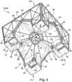
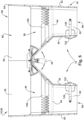
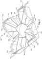
- the hood 52 has an upper portion 60 with a generally square, box-shaped configuration with four intersecting side walls 62 that intersect each other and define a peripheral end 64 for being placed against the ceiling 16 (see Fig. 1 ).
- the side walls 62 also define an inner space 66 of the balometer hood 52.
- the inner space 66 of the upper portion 60 has an open configuration and leads to a downstream lower portion 70 of the hood 52, which is divided into quadrants 72, each of which is identical in configuration and structure.
- the balometer hood 52 also includes a cover 150 for concealing and protecting at least a portion of the instrumentation and circuitry components (see Fig. 3 ) of the balometer 50, and for helping to direct airflow in the upper portion 60 of the balometer hood 52.
- Each quadrant 72 is partially defined internally within the hood 52 by respective pairs of internal walls 80.
- the internal walls 80 each have a sloped or angled configuration and form roof-like pitches within the inner space 66 of the hood 52.
- the internal walls 80 intersect each other at right angles, defining a valley 82 at this intersection.
- Intersecting internal walls 80 of adjacent quadrants 72 define peaks 84 at the intersection.
- Each peak 84 extends perpendicularly from a respective one of the side walls 62 toward the center of the inner space 66 of the hood 52, where the peaks intersect each other.
- Each valley 82 bisects the intersecting pair of peaks 84 that define its quadrant 72.
- the valleys 82 also extend toward and intersect at the center of the inner space 66 of the hood 52.
- each quadrant 72 the intersecting internal walls 80 and the respective portions of the intersecting side walls 62 define an inlet portion 86 of the quadrant.
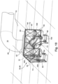
- Each quadrant 72 also includes a discharge channel 90 that extends downward (as viewed in Figs. 2-6 ) from its associated the inlet 86.
- the discharge channels 90 have a generally tubular, rectangular configuration.
- Each discharge channel 90 is defined on two sides by intersecting portions of the side walls 62, and on two sides by intersecting channel walls 92 that extend generally perpendicularly inward from the side walls toward the center of the hood 52. At their upper extent, the channel walls 92 intersect lower edge portions 94 (see Fig. 4 ) of the intersecting internal walls 80 associated with that quadrant 72.
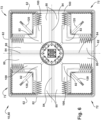
- Each quadrant 72 also includes a flow disrupting structure in the form of a turbulator 100 that is positioned in mating engagement with the inlet portion 86 of the quadrant at or near the mouth of the discharge channel 90.
- the turbulators 100 can, for example, be secured to the hood 52 via a snap fit connection.
- the turbulators 100 extend along at least a portion of the periphery of the inlet portion 86 of each quadrant, along the perimeter of the mouth of the discharge channel 90.
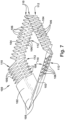
- An example of a turbulator 100 is illustrated in Fig. 7 .
- the turbulator 100 is a singular part that includes a pair of inner legs 102 and a pair of outer legs 104 that intersect each other at right angles.
- the inner legs 102 mate with and follow the slope of the intersecting internal walls 80 of the quadrant 72, and the outer legs 104 mate with and follow the generally vertically extending side walls 62 of the quadrant 72 (see, e.g., Fig. 6 ).
- Each leg 102,104 of the turbulator includes a plurality of tooth-shaped fins 106 arranged in saw tooth-like rows along the length of each leg.
- Each leg 102,104 includes an upper row 110 and a lower row 112 of fins 106.
- the fins 106 of the upper and lower rows are staggered and extend away from each other in opposite directions.
- On the outer legs 104 the fins 106 are spaced along the entire length of the legs.
- the fins 106 are spaced along approximately half the length of each leg - the half that intersects with the adjacent outer leg 104.
- the portions 108 of the inner legs 102 that are free from fins 106 have a smooth, contoured configuration, with upper edges that merge smoothly with the internal walls 80.
- Each fin 106 has a configuration that tapers from a widened base to a pointed tip.
- the fins 106 of both the upper and lower rows 110,112 of fins taper along the width of the fin as measured in the direction of the length of the legs 102,104. Additionally, the fins 106 of the upper row 110 also taper towards the wall 62,80 against which they abut.
- the cover has a generally square configuration with a planar square top wall 152 and four side walls 154 that extend perpendicularly from the top wall along its periphery.
- a cylindrical electronics covering wall 160 is located centrally on the top wall 152 extends perpendicularly from the top wall.
- a plurality of reinforcing ribs 162 extend from the wall 160 radially outwardly to the side walls 154.
- the side walls 154 each include a centrally located, generally V-shaped notch 170 that has a profile that matches that of the intersecting internal walls 80 of each quadrant 72.
- the internal walls 80 can thus mate with the notches 170 and thereby help support the cover 150 when assembled with the balometer hood 52.
- the side walls 154 have lower edge portions 172 that include a plurality of tooth-shaped notches that define a plurality of teeth 174.
- the teeth 174 extend along the length of the lower edge portions 172 and have a configuration and shape similar to the lower rows 112 of fins 106 on the turbulators 100.
- the positions and spacing of the teeth 174 on the side walls 154 of the cover 150 coincide with the portions 108 of the inner legs 102 of the turbulators 100 that are free from fins 106.
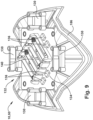
- the balometer 50 also includes instrumentation and electronics for measuring conditions associated with ambient room conditions and the airflow through the diffuser 12.
- the balometer 50 includes airflow sensing probes 120 for sensing airflow through each quadrant 72 of the balometer hood 52.
- An airflow probe 120 is positioned in each discharge channel 90.
- the probe 120 enters the discharge channel 90 through the channel walls 92 at the location where the walls intersect.
- the discharge channel 90 is fit with a probe support 122 that has portions that interlock with mating portions of the probe 122.
- the probe 120 extends through the probe support 122 and enters the discharge channel 90 through the intersecting channel walls 92.
- the probe 120 extends at an angle that bisects the intersecting walls 92, and is held in place by the probe support 122 so that an end portion 124 of the probe is positioned centrally and in the proper orientation within the discharge channel 90.
- the airflow sensing probes 120 can have a variety of configurations.
- the probes 120 comprise hot point anemometer airflow sensing probes.
- each pressure transducer 130 has a pressure port in fluid communication with the air pressure in the discharge channel 90 of the associated quadrant 72, and a port in fluid communication (e.g., via a tube) with the air pressure outside the balometer hood 52.
- the instrumentation of the balometer 50 also includes temperature sensing components for measuring the temperature of the air flowing through the balometer.
- the temperature sensing components can, for example, be a resistive, e.g., thermocouple-type, element.
- the resistive elements of the anemometers themselves can also be used to measure the airflow temperature.
- one or more separate temperature sensors can be employed.
- the pressure transducers 130 and the airflow probes 120 are connected electrically to an electronics unit 132 that is mounted to the balometer hood 52, centrally beneath the cover.
- the electronics unit 132 includes a circuit board 134 to which the pressure transducers 130 can be mounted. Alternatively, the pressure transducers can be mounted to the structure of the balometer 50.
- the electronics unit 132 includes various electronic components 136, such as processors, communication (e.g., Bluetooth) components, signal conditioning components, power and grounding circuits, communication buses, and any other components necessary to operate as described herein.
- the pressure transducers 130 and airflow probes 120 can be connected to the electronics unit 132, for example, via cables that interconnect with sockets mounted on the circuit board 134.
- the balometer 150 also includes a power supply 140, such as a battery pack, that is also located under the cover 150.
- the power supply can, for example, be mounted to the circuit board 134, on a side that is the same or opposite that to which the electronic components 136 are mounted.
- the user 30 positions the balometer 50 over the diffuser 12 using the pole 20.
- the upper portion 60 of the balometer hood 52 collects the air discharged from the diffuser 12 and directs it into the quadrants 72.
- the air directed into each quadrant 72 passes through the discharge channel 90 and over the sensor probes.
- the user 30 activates the balometer 50 via the trigger 24 on the handle 22, and the flow rate is measured via the sensor probes 120.
- the electronics unit 132 transmits readings obtained from the probes 120 wirelessly to the smart device 26.
- the smart device 26 receives and processes the readings, and displays data related to the readings for the user to interpret. Since the readings from each sensor probe 120 is related to the flow through an associated discharge channel 90, and because the total air flow is divided between the discharge channels, calculating the total flow through the balometer 50 requires a summation of the flows through individual discharge channels.
- each discharge channel 90 Since the position of the sensor probe 120 in each discharge channel 90 is fixed, it is important that the bulk flow through each discharge channel is as uniform as possible so that an accurate flow measurement can be obtained. This holds true even if the airflow is distributed unevenly through the four quadrants 72. As long as the bulk flow through each discharge channel 90 is distributed evenly within that channel, the flow measurement for that quadrant will be accurate, as will the calculated total flow for the diffuser 12.
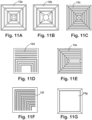
- FIGs. 11A-11J are summarized in the following table:
- the configuration of the diffuser will help dictate the airflow pattern in any balometer.
- the diffuser configuration will also determine whether the airflow is distributed evenly or unevenly across the balometer.
- All of the diffuser designs illustrated in Figs. 11A-11J direct the discharged air in an outward and downward direction.
- Diffusers 12a-12c, 12g, and 12j direct the air in four directions and would theoretically direct the air evenly in terms of direction into the balometer hood.
- Diffusers 12d-12f direct the air in three directions and would therefore direct the air unevenly into the balometer hood.
- Diffusers 12h and 12i direct the air in two and one direction, respectively, and would therefore also direct the air unevenly into the balometer hood.
- the balometer 50 is adapted to help account for these deficiencies.
- the balometer 50 is configured to divide the airflow from the diffuser 12 into the quadrants 72 in order to confine the divided flows to a more manageable space.
- the turbulators 100 in each quadrant 72 disrupt and mix the airflow to produce an even bulk flow through each discharge channel 90. This having been done, the airflow measurements taken in each discharge channel 90 are accurate and will produce an accurate calculation of total airflow through the diffuser.
- the diffuser 12 has a 3-cone square 4-way configuration and therefore directs the airflow toward all four side walls 62 of the balometer hood 52. Because of this, the bulk airflow, if left unchecked, would tend to flow along the side walls 62 toward the discharge channels 90. At the same time, the portion of the airflow that does not flow along the side walls 62 is collected and funneled toward the discharge channel 90 by the converging, sloped configuration of the internal walls 80. As the airflow is directed toward the discharge channel 90, however, the turbulators 100 redirect portions of the airflow, causing it to mix and distribute more uniformly across the discharge channel. Because the airflow is distributed uniformly across the channels 90, the small portions of the airflow that is sampled by the sensor probes 120 is much more likely to present an accurate measurement of the airflow through the discharge channel 90.
- the combination of dividing the airflow from the diffuser 12 into the four quadrants 72 and mixing the airflow in each quadrant via the turbulators 100 helps produce these results.
- the accuracy of the balometer 50 can be affected by the amount of airflow resistance, or backpressure, that is introduced by placing the balometer in the airstream. Generally speaking, the lower the backpressure introduced by the presence of the balometer 50, the better. Mixing the flow to improve the uniformity of the airflow through the balometer 50, however, necessarily adds to the backpressure introduced by the balometer. To adequately mix the flow through the single flow channel of a conventional balometer hood would require a high degree of mixing and yet still may not result in even flow distribution. In fact, the magnitude of flow mixing necessary to produce uniform flow through the conventional balometer would likely create airflow disruptions of such a high magnitude that an undesirably high backpressure would result.
- the balometer hood 52 of the balometer of the present invention avoids this problem by first dividing the airflow into quadrants 72 of a more manageable space. In the quadrants 72, the amount of flow disruption required to adequately mix and distribute the airflow across the discharge channels 90 is minimized. Thus, the size of the turbulator fins 106, and the magnitude of the airflow disruption within the channels 90, can be kept at a minimum, which helps minimize the amount of backpressure created by the balometer 50.
- balometer hoods average airflow measurements taken from an array of elements distributed across the hood.
- the balometer 50 sums the individual airflows measured in each channel of the divided hood. Because of this, the balometer 50 of the present invention does not rely on airflow being directed from the diffuser into the balometer hood to the same degree as conventional balometers.
- the balometer 50 is divided into quadrants 72 and relies on summing the airflow measured through each quadrant as opposed to the averaging the flow across the entire hood, there is no concern over a particular diffuser configuration causing an imbalance in certain regions of the balometer. This is because, in each quadrant 72, the airflow is funneled to the discharge channel 90 and mixed by the turbulators 100 to ensure uniform airflow distribution through the channel. Since each quadrant is measured separately, flow variances between quadrants will signal the level of imbalance across the diffuser 12. This can be due, for example, to an elbow leading to the diffuser 12, and the system 10 can compensate for any inaccuracy associated with the level of imbalance. The airflow measurement for each quadrant 72 will be accurate and, therefore, so will the total airflow measured by the system 10. Traditional air flow hoods use an averaging pitot tube with a signal differential pressure measurement, so they can neither detect these imbalances nor compensate for them.
- the application implemented by the smart device 26 can be adapted to compensate for different backflows realized by the balometer 50 for the different configurations of the diffuser and the HVAC system under test.
- compensation factors can be determined through air flow bench testing.
- the air flow bench can be configured to discharge air at a known volumetric flow rate through each of various diffuser configurations. This known flow rate can be compared to the flow rate measured via the balometer 50, and the error can be used to generate a compensation factor that will be programmed into the smart device application.
- the testing can be repeated to establish reliability and also in order to take into account other factors, such as compensation for any elbows in the ductwork leading to the diffuser and the distance between the elbow and the diffuser.
- the user 30 simply selects via the application on the smart device 26 the type of diffuser and any additional information, such as elbow distance, via the application graphical user interface (GUI).
- GUI graphical user interface
- the application will take these factors into account by applying the appropriate compensation factor to the readings obtained from the sensors 120.
- the implementation of the application on the smart device allows for further efficiencies, such as a predictive balancing algorithm that indicates to the user 30 which flows (i.e., which diffusers 12) to measure, in which order, and how to adjust the dampers on each diffuser in order to obtain system balance.
- the user 30 may be queried to enter HVAC system information via the GUI, such as the number and type of diffusers 12 in a given room or for a given branch of the VAC system, and information on elbow distances for each diffuser.
- the smart device 26 running the application can give the user 30 step-by-step instructions on how to balance the system in the most accurate and time efficient manner.
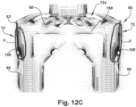
- Figs. 12A-12D compare and contrast flow patterns and velocity vectors obtained via computational fluid dynamics (CFD) modeling for a prior art air flow hood ( Figs. 12A-12B ) versus the balometer 50 ( Figs. 12C-D ).
- CFD computational fluid dynamics
- the CFD modeling illustrates airflow with vector arrows.
- the direction in which the vectors arrows point is the direction of the modeled airflow.
- the size of the vector arrows indicates the velocity of the airflow.
- the density of the vector arrows in any particular area is indicative of the density or concentration of the modeled airflow in that area.
- the conventional air flow hood H is positioned over a 3-cone, square, 4-way diffuser 12a (see Fig. 11A ).
- the airflow is concentrated along the exterior walls W of the hood H, in the areas indicated generally at A in Fig. 12A .
- the concentrated airflow flows along the walls W toward the throat T of the air flow hood H.
- airflow is less concentrated, but still flows toward the throat T.
- the airflow tends to re-circulate or swirl, as indicated by the swirling and upward pointing arrows of the CFD model.
- the flow is highly concentrated along the walls W, as indicated by the dense, dark collection of arrows, in the areas indicated generally at C.
- the swirling and recirculation in the upper region C of the hood H will inhibit flow through the register 12a, which will cause an increase in backpressure in the HVAC system. Increased backpressure will reduce the flow through the register 12a and through the air flow hood H.
- the conventional air flow hood H suffer from the non-uniform flow patterns through the hood, it also suffers from the reduced flow that results from its use. Therefore, the accuracy and repeatability of the measurements obtained via the conventional air flow hood H is therefore questionable.
- the conventional air flow hood H is positioned over a square, one way diffuser 12i (see Fig. 11I ).
- the airflow is concentrated along the exterior wall W of the hood H toward which the one-way diffuser 12i directs the air, as shown in the area indicated generally at A in Fig. 12B .
- As indicated generally at B there is an area of less concentrated airflow toward the throat T, but this area is small and irregular.
- D at or near the throat T, airflow is highly concentrated along the walls W, especially the wall along which the bulk airflow A occurs.
- the square, one way diffuser 12a directs the bulk airflow along one wall W of the conventional air flow hood H and also produces a high degree of swirling and recirculation throughout the hood.
- the averaging pitot tube manometer is unlikely to accurately measure the velocity of the highly non-uniform airflow pattern illustrated in Fig. 12B , and the high degree of swirling and recirculation will increase backpressure, which will reduce the flow through the air flow hood H.
- the accuracy and repeatability of the measurements obtained via the conventional air flow hood H is therefore questionable.
- Figs. 12C and 12D illustrate CFD models for the balometer 50 implemented in scenarios that correspond to those illustrated in Figs. 12A and 12B , respectively.
- the presence of the hood 150 streamlines flow in the upper portion 60 of the balometer hood 52, which inhibits or prevents swirling and re-circulation.
- the hood 150 directs the streamlined airflow laterally into the quadrants 72, which then direct the airflow through the discharge channels 90.
- the one-way register 12i ( Fig. 12D ) does not significantly affect the accuracy of the balometer 50. Airflow is discharged into the balometer hood 52 in unequal rates, skewed toward one of the walls, and two of the quadrants 72 (one of which is shown in Fig. 12D ). The airflow is therefore unequally distributed in the discharge channels 90. Along the outer walls of the balometer hood 52 on the strong side of the diffuser 12i, airflow does tend to concentrate, as indicated generally by the regions identified at F in Fig. 12D . Additionally, on this side, there is some recirculation under the hood 150, as indicated generally by the regions identified at F in Fig. 12D .
- the presence of the turbulators 100 introduce turbulence that mixes the flow entering the discharge channels 90.
- the flow in each of the discharge channels 90 again, is substantially uniform, even if unequal.
- the sensor probes located in the discharge channels 90, would produce measurements that, while not equal, are accurate, and those accurate measurements would yield accurate and repeatable airflow calculations.
Landscapes
- Engineering & Computer Science (AREA)
- Mechanical Engineering (AREA)
- General Engineering & Computer Science (AREA)
- Physics & Mathematics (AREA)
- Fluid Mechanics (AREA)
- Chemical & Material Sciences (AREA)
- Combustion & Propulsion (AREA)
- General Physics & Mathematics (AREA)
- Measuring Volume Flow (AREA)
- Air Conditioning Control Device (AREA)
Claims (13)
- Balomètre (48) pour mesurer le flux d'air au travers d'un diffuseur (12) d'un système HVAC (14), comprenant :une hotte (42, 52) qui présente une configuration générale en forme de boîte rectangulaire configurée pour coopérer avec la configuration du diffuseur (12) et pour être positionnée directement au-dessus du diffuseur (12) et contre le plafond le long d'un périmètre de diffuseur de telle sorte que la totalité du flux d'air déchargé depuis le diffuseur (12) est dirigée à l'intérieur de la hotte (42, 52),dans lequel la hotte (52) comprend une partie supérieure (60) qui définit un espace ouvert à l'intérieur duquel un flux d'air est déchargé, et dans lequel la hotte (52) comprend quatre quadrants (72), chaque quadrant (72) incluant l'un d'une pluralité de canaux de décharge (90),et dans lequel la hotte (42, 52) comprend des parois internes configurées pour diviser et canaliser le flux d'air au travers de la pluralité de canaux de décharge (90) et définissant les quadrants (72) au travers desquels le flux d'air divisé est dirigé, les parois internes (80) et les canaux de décharge (90) étant positionnés en aval de la partie supérieure (60), et dans lequel les parois internes présentent une configuration de crête et descendent de manière convergente en direction des canaux de décharge, etdans lequel le balomètre (48) comprend en outre une instrumentation et une électronique pour mesurer des conditions associées à des conditions d'atmosphère ambiante et au flux d'air au travers du diffuseur (12), ladite instrumentation comprenant des sondes de capteur (120) pour mesurer le flux d'air au travers de chaque canal de décharge (90), dans lequel une sonde de capteur (120) est positionnée dans chaque canal de décharge (90).
- Balomètre (48) selon la revendication 1, dans lequel la hotte (42, 52) comprend des structures perturbatrices de flux (100) pour mélanger et répartir le flux d'air de façon uniforme au travers des canaux de décharge (90).
- Balomètre (48) selon la revendication 2, dans lequel les structures perturbatrices de flux (100) comprennent des turbulateurs ; oudans lequel les structures perturbatrices de flux comprennent une pluralité d'ailettes en forme de dent (106) agencées selon des rangées à la façon des dents d'une scie ; oudans lequel les structures perturbatrices de flux (100) sont positionnées de manière adjacente à des entrées (86) des canaux de décharge (90).
- Balomètre (48) selon la revendication 1, dans lequel chaque quadrant (72) comprend au moins une structure perturbatrice de flux (100) pour mélanger et répartir le flux d'air de façon uniforme au travers des canaux de décharge (90), et optionnellement
dans lequel les structures perturbatrices de flux (100) sont positionnées de manière adjacente à des entrées (86) des canaux de décharge (90). - Balomètre (48) selon la revendication 1, comprenant en outre une surface plane (152), positionnée dans une partie supérieure (60) de la hotte (52), qui dirige le flux d'air en direction des canaux de décharge (90) et lui donne un profil aérodynamique, et
optionnellement, dans lequel la surface plane (152) réduit le volume de la partie supérieure (60) et contribue ainsi à empêcher un tourbillon dans le flux d'air dans la partie supérieure (60) de la hotte. - Balomètre (48) selon la revendication 5, dans lequel la surface plane (152) est une partie supérieure d'un élément de recouvrement (150) au-dessous duquel une instrumentation et une électronique sont localisées ; optionnellement
dans lequel l'instrumentation comprend au moins un transducteur parmi des transducteurs de pression (130) et de température. - Balomètre (48) selon la revendication 1, comprenant en outre :une électronique pour interroger les sondes de capteur (120) et transmettre des signaux sans fil comprenant des données de mesure obtenues via les sondes de capteur (120) ; etun dispositif intelligent (26) pour recevoir les signaux sans fil et traiter les données de mesure pour fournir des données de mesure de flux d'air pour le diffuseur (12),optionnellement, dans lequel le dispositif intelligent (26) comprend un dispositif parmi un téléphone intelligent ou une tablette muni(e) d'une application pour traiter les données de mesure de flux d'air et comprenant une interface utilisateur graphique pour afficher des informations rapportées aux données de mesure et au système HVAC (14).
- Balomètre (48) selon la revendication 1, comprenant en outre une structure de montage de perche (36) localisée centralement sur un côté inférieur de la hotte (52), la structure de montage de perche (36) étant adaptée pour recevoir une perche (20) qu'un utilisateur (30) peut manipuler pour manoeuvrer la hotte (52) en une position souhaitée de manière adjacente au diffuseur,
optionnellement, dans lequel la structure de montage de perche comprend un mécanisme de basculement (36) pour permettre le pivotement de la perche (20) par rapport à la hotte (52). - Balomètre (48) selon la revendication 8, dans lequel le balomètre (48) comprend en outre une perche (20), etdans lequel la perche (20) présente une construction télescopique qui permet le réglage de la longueur de la perche (20) pour faciliter le positionnement de la hotte (52) de manière adjacente au diffuseur (12) pendant le positionnement d'une base (32) de la perche (20) contre une surface de sorte que la surface supporte au moins une partie du poids de la hotte (52),optionnellement, dans lequel la perche (20) comprend un manche (22) que l'utilisateur (30) peut saisir pour manoeuvrer la hotte (52), le manche (22) comprenant un élément de déclenchement (22) pouvant être actionné à l'aide d'un doigt pour fournir un signal sans fil pour activer une électronique de système.
- Balomètre (48) selon la revendication 1, dans lequel les sondes de capteur (120) comprennent des capteurs anémométriques à point(s) chaud(s).
- Procédé pour mesurer un flux d'air au travers d'un diffuseur (12) d'un système HVAC (14) en utilisant le balomètre selon l'une quelconque des revendications précédentes, comprenant :le recueil du flux d'air déchargé depuis le diffuseur (12) à l'intérieur de la hotte (42, 52) ;la division du flux d'air dans la hotte en utilisant les parois internes ;la canalisation du flux d'air divisé au travers d'une pluralité de canaux de décharge (90) en utilisant les quadrants ; etla mesure d'un flux d'air au travers du diffuseur (12) en utilisant une instrumentation et une électronique pour mesurer des conditions associées à des conditions d'atmosphère ambiante et au flux d'air au travers du diffuseur (12), dans lequel la mesure d'un flux d'air au travers du diffuseur (12) comprend la mesure du flux d'air au travers de chaque canal de décharge (90) en utilisant une pluralité de sondes de capteur (120), dans lequel une sonde de capteur (120) est située dans chaque canal de décharge (90).
- Procédé selon la revendication 11, comprenant en outre la perturbation du flux d'air pour mélanger et répartir le flux d'air de façon uniforme au travers des canaux de décharge.
- Procédé selon la revendication 11, comprenant en outre le fait de donner un profil aérodynamique au flux d'air dans la région à proximité du diffuseur (12) et la direction du flux d'air vers une structure pour diviser le flux d'air.
Applications Claiming Priority (2)
| Application Number | Priority Date | Filing Date | Title |
|---|---|---|---|
| US201562121222P | 2015-02-26 | 2015-02-26 | |
| PCT/US2016/019069 WO2016137952A1 (fr) | 2015-02-26 | 2016-02-23 | Hotte à flux d'air |
Publications (2)
| Publication Number | Publication Date |
|---|---|
| EP3274635A1 EP3274635A1 (fr) | 2018-01-31 |
| EP3274635B1 true EP3274635B1 (fr) | 2024-10-16 |
Family
ID=55451592
Family Applications (1)
| Application Number | Title | Priority Date | Filing Date |
|---|---|---|---|
| EP16707609.0A Active EP3274635B1 (fr) | 2015-02-26 | 2016-02-23 | Hotte à flux d'air |
Country Status (7)
| Country | Link |
|---|---|
| US (2) | US10001151B2 (fr) |
| EP (1) | EP3274635B1 (fr) |
| JP (1) | JP2018511790A (fr) |
| CN (1) | CN108351117A (fr) |
| BR (1) | BR112017018247A8 (fr) |
| CO (1) | CO2017008959A2 (fr) |
| WO (1) | WO2016137952A1 (fr) |
Families Citing this family (7)
| Publication number | Priority date | Publication date | Assignee | Title |
|---|---|---|---|---|
| US10671098B2 (en) * | 2015-12-21 | 2020-06-02 | Dwyer Instruments, Inc. | System, method, and apparatus for balancing an HVAC system |
| USD854678S1 (en) * | 2017-06-30 | 2019-07-23 | Dwyer Instruments, Inc. | HVAC airflow hood |
| US10697992B1 (en) | 2017-09-21 | 2020-06-30 | Evergreen Telemetry Llc | Airflow capture hood |
| US12013279B2 (en) * | 2020-04-06 | 2024-06-18 | Kane Usa, Inc. | Volume fill airflow measurement |
| KR102418022B1 (ko) * | 2020-07-04 | 2022-07-06 | 김청균 | 환기구용 스마트 댐퍼 내장형 후드캡 유니트 및 시공용 윈치 |
| US11415593B1 (en) * | 2021-05-26 | 2022-08-16 | Chevron U.S.A. Inc. | Multiplexing apparatus for measuring air flow and air temperature |
| US11754585B1 (en) * | 2022-11-29 | 2023-09-12 | James Stainner | Air velocity measuring device |
Citations (4)
| Publication number | Priority date | Publication date | Assignee | Title |
|---|---|---|---|---|
| US3748901A (en) * | 1971-03-31 | 1973-07-31 | Air Monitor Corp | Air flow balancing device |
| JPH04115026U (ja) * | 1991-03-27 | 1992-10-12 | 株式会社フジタ | 風量計測ダクト |
| JPH07103800A (ja) * | 1993-10-07 | 1995-04-18 | Fujitsu Ltd | 風量測定器 |
| US5667189A (en) * | 1995-04-13 | 1997-09-16 | Kester; Michael H. | Self-supporting flow hood |
Family Cites Families (22)
| Publication number | Priority date | Publication date | Assignee | Title |
|---|---|---|---|---|
| US3685355A (en) * | 1970-04-13 | 1972-08-22 | Air Monitor Corp | Air monitoring system |
| JPS4943290B1 (fr) * | 1970-06-05 | 1974-11-20 | ||
| US3733900A (en) * | 1971-11-22 | 1973-05-22 | Air Monitor Corp | Fan capacity measuring station |
| US4030358A (en) * | 1975-11-10 | 1977-06-21 | Cambridge Filter Corporation | Portable air velocity measuring unit |
| US4481829A (en) * | 1983-02-01 | 1984-11-13 | Shortridge Ernest R | Manifold apparatus for airflow sensing equipment |
| JPS61210912A (ja) * | 1985-03-15 | 1986-09-19 | Toyota Central Res & Dev Lab Inc | 空気流量測定装置 |
| CN1049284C (zh) * | 1994-09-30 | 2000-02-09 | 中国矿业大学 | 通风机风量在线监测的引压装置及其监测方法 |
| US5786525A (en) * | 1996-04-09 | 1998-07-28 | Johnson Service Company | Method and apparatus for balancing an air distribution system |
| JPH11271106A (ja) * | 1998-03-20 | 1999-10-05 | Mitsubishi Electric Corp | 吹出し口風量測定具 |
| US6439061B1 (en) * | 1999-03-31 | 2002-08-27 | The Energy Conservatory | Airflow measuring assembly for air handling systems |
| US7147168B1 (en) * | 2003-08-11 | 2006-12-12 | Halton Company | Zone control of space conditioning system with varied uses |
| JP2004257842A (ja) * | 2003-02-26 | 2004-09-16 | Shinryo Corp | 空調用制気口の風量風温測定装置 |
| US7344089B1 (en) * | 2003-03-24 | 2008-03-18 | Sutterfield Bill R | Wireless air-volume damper control system |
| JP2006236074A (ja) * | 2005-02-25 | 2006-09-07 | Toshiba Corp | 検針装置、無線タグ検針システム及び検針方法 |
| SE533651C2 (sv) * | 2007-03-19 | 2010-11-23 | Mikael Nutsos | Till- eller frånluftsdon med flödesindikator |
| US7706673B1 (en) * | 2007-04-06 | 2010-04-27 | Staudinger Robert J | Portable remote camera control device |
| US8641006B2 (en) * | 2008-03-28 | 2014-02-04 | David C. Reichel | Hands-free capture hood support device and method |
| US9605857B2 (en) * | 2010-08-11 | 2017-03-28 | Evergreen Telemetry Llc | Wireless sensors system and method of using same |
| US9052059B2 (en) * | 2011-04-20 | 2015-06-09 | Pius Ileogben | Apparatus and method for elevating and supporting an air flow measuring device |
| ITMI20111538A1 (it) | 2011-08-12 | 2013-02-13 | Marco Zambolin | Procedimento per la regolazione della portata di aria in un impianto per il trattamento dell'aria e relativo impianto |
| JP5921361B2 (ja) * | 2012-06-25 | 2016-05-24 | 株式会社日立製作所 | 空調システムの風量測定装置 |
| DE102014000241B4 (de) * | 2014-01-10 | 2015-04-16 | Testo Ag | Volumenstrommessgerät |
-
2016
- 2016-02-23 WO PCT/US2016/019069 patent/WO2016137952A1/fr not_active Ceased
- 2016-02-23 JP JP2017545216A patent/JP2018511790A/ja active Pending
- 2016-02-23 BR BR112017018247A patent/BR112017018247A8/pt not_active Application Discontinuation
- 2016-02-23 CN CN201680012610.0A patent/CN108351117A/zh active Pending
- 2016-02-23 EP EP16707609.0A patent/EP3274635B1/fr active Active
- 2016-02-23 US US15/050,813 patent/US10001151B2/en active Active
-
2017
- 2017-08-31 CO CONC2017/0008959A patent/CO2017008959A2/es unknown
-
2018
- 2018-05-30 US US15/992,621 patent/US20180274570A1/en not_active Abandoned
Patent Citations (4)
| Publication number | Priority date | Publication date | Assignee | Title |
|---|---|---|---|---|
| US3748901A (en) * | 1971-03-31 | 1973-07-31 | Air Monitor Corp | Air flow balancing device |
| JPH04115026U (ja) * | 1991-03-27 | 1992-10-12 | 株式会社フジタ | 風量計測ダクト |
| JPH07103800A (ja) * | 1993-10-07 | 1995-04-18 | Fujitsu Ltd | 風量測定器 |
| US5667189A (en) * | 1995-04-13 | 1997-09-16 | Kester; Michael H. | Self-supporting flow hood |
Also Published As
| Publication number | Publication date |
|---|---|
| CO2017008959A2 (es) | 2018-01-31 |
| BR112017018247A2 (pt) | 2019-04-30 |
| US10001151B2 (en) | 2018-06-19 |
| EP3274635A1 (fr) | 2018-01-31 |
| WO2016137952A1 (fr) | 2016-09-01 |
| US20180274570A1 (en) | 2018-09-27 |
| BR112017018247A8 (pt) | 2022-10-11 |
| US20160252114A1 (en) | 2016-09-01 |
| JP2018511790A (ja) | 2018-04-26 |
| CN108351117A (zh) | 2018-07-31 |
Similar Documents
| Publication | Publication Date | Title |
|---|---|---|
| EP3274635B1 (fr) | Hotte à flux d'air | |
| US9074917B2 (en) | Apparatus for measurement of ducted air | |
| US10671098B2 (en) | System, method, and apparatus for balancing an HVAC system | |
| US4481829A (en) | Manifold apparatus for airflow sensing equipment | |
| US6439061B1 (en) | Airflow measuring assembly for air handling systems | |
| AU2018290776A1 (en) | Pitot tube instrument | |
| US12066199B2 (en) | Airstream sensor devices, systems and methods | |
| KR101415882B1 (ko) | 풍량 측정용 정압탭이 구비된 이동식 디지털 풍량 측정장치 | |
| CN215726268U (zh) | 流量传感器检定系统 | |
| CN113624303A (zh) | 流量传感器检定系统 | |
| US12031999B2 (en) | Air velocity measuring device | |
| JP6934874B2 (ja) | Hvacシステムのバランス調整をするためのシステム、方法、装置 | |
| JPH0576566B2 (fr) | ||
| US11604085B1 (en) | Airflow measurement device for airflow measuring | |
| CN207585667U (zh) | 一种双温双压均温水槽 | |
| La Fianza et al. | Thermo-fluid-dynamic characteristics of confluent jets for distribution of treated air in small environment | |
| Wray | Evaluation of flow capture techniques for measuring HVAC grille airflows | |
| Svensson | Methods for measurement of air flow rates in ventilation systems | |
| Hatton et al. | A study of the air quality in the breathing zone. | |
| Braconnier et al. | Fluid dynamics of cytotoxic safety cabinets | |
| JP2017040620A (ja) | 風量計 | |
| Walker et al. | Evaluation of commercially available techniques and development of simplified methods for measuring grille airflows in HVAC systems | |
| SMOLJAN et al. | Utjecaj konstrukcije priključne kutije vrtložnog difuzora na uniformnost radijalnog zračnog mlaza | |
| Palmiter et al. | Development of a Simple Device for Field Air Flow Measurement of Residential Air Handling Equipment | |
| Walker et al. | Laboratory Evaluation of Air Flow Measurement Methods for Residential HVAC Returns |
Legal Events
| Date | Code | Title | Description |
|---|---|---|---|
| STAA | Information on the status of an ep patent application or granted ep patent |
Free format text: STATUS: THE INTERNATIONAL PUBLICATION HAS BEEN MADE |
|
| PUAI | Public reference made under article 153(3) epc to a published international application that has entered the european phase |
Free format text: ORIGINAL CODE: 0009012 |
|
| STAA | Information on the status of an ep patent application or granted ep patent |
Free format text: STATUS: REQUEST FOR EXAMINATION WAS MADE |
|
| 17P | Request for examination filed |
Effective date: 20170905 |
|
| AK | Designated contracting states |
Kind code of ref document: A1 Designated state(s): AL AT BE BG CH CY CZ DE DK EE ES FI FR GB GR HR HU IE IS IT LI LT LU LV MC MK MT NL NO PL PT RO RS SE SI SK SM TR |
|
| AX | Request for extension of the european patent |
Extension state: BA ME |
|
| DAV | Request for validation of the european patent (deleted) | ||
| DAX | Request for extension of the european patent (deleted) | ||
| RIC1 | Information provided on ipc code assigned before grant |
Ipc: F24F 13/06 20060101ALI20160909BHEP Ipc: F24F 11/02 20181130AFI20160909BHEP Ipc: F24F 11/00 20180101ALI20160909BHEP |
|
| RIC1 | Information provided on ipc code assigned before grant |
Ipc: F24F 11/02 20060101AFI20160909BHEP Ipc: F24F 13/06 20060101ALI20160909BHEP Ipc: F24F 11/00 20180101ALI20160909BHEP |
|
| STAA | Information on the status of an ep patent application or granted ep patent |
Free format text: STATUS: EXAMINATION IS IN PROGRESS |
|
| 17Q | First examination report despatched |
Effective date: 20190712 |
|
| P01 | Opt-out of the competence of the unified patent court (upc) registered |
Effective date: 20230528 |
|
| REG | Reference to a national code |
Ref country code: DE Ref legal event code: R079 Free format text: PREVIOUS MAIN CLASS: F24F0011020000 Ipc: F24F0110300000 Ref document number: 602016089845 Country of ref document: DE |
|
| GRAP | Despatch of communication of intention to grant a patent |
Free format text: ORIGINAL CODE: EPIDOSNIGR1 |
|
| STAA | Information on the status of an ep patent application or granted ep patent |
Free format text: STATUS: GRANT OF PATENT IS INTENDED |
|
| RIC1 | Information provided on ipc code assigned before grant |
Ipc: F24F 13/06 20060101ALI20240306BHEP Ipc: F24F 11/74 20180101ALI20240306BHEP Ipc: F24F 110/30 20180101AFI20240306BHEP |
|
| INTG | Intention to grant announced |
Effective date: 20240322 |
|
| GRAS | Grant fee paid |
Free format text: ORIGINAL CODE: EPIDOSNIGR3 |
|
| GRAA | (expected) grant |
Free format text: ORIGINAL CODE: 0009210 |
|
| STAA | Information on the status of an ep patent application or granted ep patent |
Free format text: STATUS: THE PATENT HAS BEEN GRANTED |
|
| AK | Designated contracting states |
Kind code of ref document: B1 Designated state(s): AL AT BE BG CH CY CZ DE DK EE ES FI FR GB GR HR HU IE IS IT LI LT LU LV MC MK MT NL NO PL PT RO RS SE SI SK SM TR |
|
| RAP3 | Party data changed (applicant data changed or rights of an application transferred) |
Owner name: DWYER INSTRUMENTS, LLC |
|
| REG | Reference to a national code |
Ref country code: GB Ref legal event code: FG4D |
|
| REG | Reference to a national code |
Ref country code: CH Ref legal event code: EP |
|
| REG | Reference to a national code |
Ref country code: IE Ref legal event code: FG4D |
|
| REG | Reference to a national code |
Ref country code: DE Ref legal event code: R096 Ref document number: 602016089845 Country of ref document: DE |
|
| REG | Reference to a national code |
Ref country code: LT Ref legal event code: MG9D |
|
| REG | Reference to a national code |
Ref country code: NL Ref legal event code: MP Effective date: 20241016 |
|
| REG | Reference to a national code |
Ref country code: AT Ref legal event code: MK05 Ref document number: 1733193 Country of ref document: AT Kind code of ref document: T Effective date: 20241016 |
|
| PG25 | Lapsed in a contracting state [announced via postgrant information from national office to epo] |
Ref country code: NL Free format text: LAPSE BECAUSE OF FAILURE TO SUBMIT A TRANSLATION OF THE DESCRIPTION OR TO PAY THE FEE WITHIN THE PRESCRIBED TIME-LIMIT Effective date: 20241016 |
|
| PG25 | Lapsed in a contracting state [announced via postgrant information from national office to epo] |
Ref country code: NL Free format text: LAPSE BECAUSE OF FAILURE TO SUBMIT A TRANSLATION OF THE DESCRIPTION OR TO PAY THE FEE WITHIN THE PRESCRIBED TIME-LIMIT Effective date: 20241016 |
|
| PG25 | Lapsed in a contracting state [announced via postgrant information from national office to epo] |
Ref country code: HR Free format text: LAPSE BECAUSE OF FAILURE TO SUBMIT A TRANSLATION OF THE DESCRIPTION OR TO PAY THE FEE WITHIN THE PRESCRIBED TIME-LIMIT Effective date: 20241016 Ref country code: IS Free format text: LAPSE BECAUSE OF FAILURE TO SUBMIT A TRANSLATION OF THE DESCRIPTION OR TO PAY THE FEE WITHIN THE PRESCRIBED TIME-LIMIT Effective date: 20250216 Ref country code: PT Free format text: LAPSE BECAUSE OF FAILURE TO SUBMIT A TRANSLATION OF THE DESCRIPTION OR TO PAY THE FEE WITHIN THE PRESCRIBED TIME-LIMIT Effective date: 20250217 |
|
| PG25 | Lapsed in a contracting state [announced via postgrant information from national office to epo] |
Ref country code: FI Free format text: LAPSE BECAUSE OF FAILURE TO SUBMIT A TRANSLATION OF THE DESCRIPTION OR TO PAY THE FEE WITHIN THE PRESCRIBED TIME-LIMIT Effective date: 20241016 |
|
| PG25 | Lapsed in a contracting state [announced via postgrant information from national office to epo] |
Ref country code: BG Free format text: LAPSE BECAUSE OF FAILURE TO SUBMIT A TRANSLATION OF THE DESCRIPTION OR TO PAY THE FEE WITHIN THE PRESCRIBED TIME-LIMIT Effective date: 20241016 |
|
| PG25 | Lapsed in a contracting state [announced via postgrant information from national office to epo] |
Ref country code: ES Free format text: LAPSE BECAUSE OF FAILURE TO SUBMIT A TRANSLATION OF THE DESCRIPTION OR TO PAY THE FEE WITHIN THE PRESCRIBED TIME-LIMIT Effective date: 20241016 |
|
| PG25 | Lapsed in a contracting state [announced via postgrant information from national office to epo] |
Ref country code: NO Free format text: LAPSE BECAUSE OF FAILURE TO SUBMIT A TRANSLATION OF THE DESCRIPTION OR TO PAY THE FEE WITHIN THE PRESCRIBED TIME-LIMIT Effective date: 20250116 |
|
| PG25 | Lapsed in a contracting state [announced via postgrant information from national office to epo] |
Ref country code: LV Free format text: LAPSE BECAUSE OF FAILURE TO SUBMIT A TRANSLATION OF THE DESCRIPTION OR TO PAY THE FEE WITHIN THE PRESCRIBED TIME-LIMIT Effective date: 20241016 Ref country code: AT Free format text: LAPSE BECAUSE OF FAILURE TO SUBMIT A TRANSLATION OF THE DESCRIPTION OR TO PAY THE FEE WITHIN THE PRESCRIBED TIME-LIMIT Effective date: 20241016 Ref country code: GR Free format text: LAPSE BECAUSE OF FAILURE TO SUBMIT A TRANSLATION OF THE DESCRIPTION OR TO PAY THE FEE WITHIN THE PRESCRIBED TIME-LIMIT Effective date: 20250117 |
|
| PG25 | Lapsed in a contracting state [announced via postgrant information from national office to epo] |
Ref country code: PL Free format text: LAPSE BECAUSE OF FAILURE TO SUBMIT A TRANSLATION OF THE DESCRIPTION OR TO PAY THE FEE WITHIN THE PRESCRIBED TIME-LIMIT Effective date: 20241016 |
|
| PG25 | Lapsed in a contracting state [announced via postgrant information from national office to epo] |
Ref country code: RS Free format text: LAPSE BECAUSE OF FAILURE TO SUBMIT A TRANSLATION OF THE DESCRIPTION OR TO PAY THE FEE WITHIN THE PRESCRIBED TIME-LIMIT Effective date: 20250116 |
|
| PG25 | Lapsed in a contracting state [announced via postgrant information from national office to epo] |
Ref country code: SM Free format text: LAPSE BECAUSE OF FAILURE TO SUBMIT A TRANSLATION OF THE DESCRIPTION OR TO PAY THE FEE WITHIN THE PRESCRIBED TIME-LIMIT Effective date: 20241016 |
|
| PG25 | Lapsed in a contracting state [announced via postgrant information from national office to epo] |
Ref country code: DK Free format text: LAPSE BECAUSE OF FAILURE TO SUBMIT A TRANSLATION OF THE DESCRIPTION OR TO PAY THE FEE WITHIN THE PRESCRIBED TIME-LIMIT Effective date: 20241016 |
|
| REG | Reference to a national code |
Ref country code: DE Ref legal event code: R097 Ref document number: 602016089845 Country of ref document: DE |
|
| PG25 | Lapsed in a contracting state [announced via postgrant information from national office to epo] |
Ref country code: EE Free format text: LAPSE BECAUSE OF FAILURE TO SUBMIT A TRANSLATION OF THE DESCRIPTION OR TO PAY THE FEE WITHIN THE PRESCRIBED TIME-LIMIT Effective date: 20241016 |
|
| PG25 | Lapsed in a contracting state [announced via postgrant information from national office to epo] |
Ref country code: RO Free format text: LAPSE BECAUSE OF FAILURE TO SUBMIT A TRANSLATION OF THE DESCRIPTION OR TO PAY THE FEE WITHIN THE PRESCRIBED TIME-LIMIT Effective date: 20241016 |
|
| PG25 | Lapsed in a contracting state [announced via postgrant information from national office to epo] |
Ref country code: SK Free format text: LAPSE BECAUSE OF FAILURE TO SUBMIT A TRANSLATION OF THE DESCRIPTION OR TO PAY THE FEE WITHIN THE PRESCRIBED TIME-LIMIT Effective date: 20241016 |
|
| PG25 | Lapsed in a contracting state [announced via postgrant information from national office to epo] |
Ref country code: CZ Free format text: LAPSE BECAUSE OF FAILURE TO SUBMIT A TRANSLATION OF THE DESCRIPTION OR TO PAY THE FEE WITHIN THE PRESCRIBED TIME-LIMIT Effective date: 20241016 |
|
| PLBE | No opposition filed within time limit |
Free format text: ORIGINAL CODE: 0009261 |
|
| STAA | Information on the status of an ep patent application or granted ep patent |
Free format text: STATUS: NO OPPOSITION FILED WITHIN TIME LIMIT |
|
| PG25 | Lapsed in a contracting state [announced via postgrant information from national office to epo] |
Ref country code: SE Free format text: LAPSE BECAUSE OF FAILURE TO SUBMIT A TRANSLATION OF THE DESCRIPTION OR TO PAY THE FEE WITHIN THE PRESCRIBED TIME-LIMIT Effective date: 20241016 |
|
| PG25 | Lapsed in a contracting state [announced via postgrant information from national office to epo] |
Ref country code: MC Free format text: LAPSE BECAUSE OF FAILURE TO SUBMIT A TRANSLATION OF THE DESCRIPTION OR TO PAY THE FEE WITHIN THE PRESCRIBED TIME-LIMIT Effective date: 20241016 |
|
| 26N | No opposition filed |
Effective date: 20250717 |
|
| REG | Reference to a national code |
Ref country code: CH Ref legal event code: PL |
|
| PG25 | Lapsed in a contracting state [announced via postgrant information from national office to epo] |
Ref country code: LU Free format text: LAPSE BECAUSE OF NON-PAYMENT OF DUE FEES Effective date: 20250223 |
|
| PG25 | Lapsed in a contracting state [announced via postgrant information from national office to epo] |
Ref country code: CH Free format text: LAPSE BECAUSE OF NON-PAYMENT OF DUE FEES Effective date: 20250228 |
|
| REG | Reference to a national code |
Ref country code: BE Ref legal event code: MM Effective date: 20250228 |
|
| PG25 | Lapsed in a contracting state [announced via postgrant information from national office to epo] |
Ref country code: BE Free format text: LAPSE BECAUSE OF NON-PAYMENT OF DUE FEES Effective date: 20250228 |
|
| PG25 | Lapsed in a contracting state [announced via postgrant information from national office to epo] |
Ref country code: IE Free format text: LAPSE BECAUSE OF NON-PAYMENT OF DUE FEES Effective date: 20250223 |
|
| PGFP | Annual fee paid to national office [announced via postgrant information from national office to epo] |
Ref country code: GB Payment date: 20260227 Year of fee payment: 11 |
|
| PGFP | Annual fee paid to national office [announced via postgrant information from national office to epo] |
Ref country code: DE Payment date: 20260227 Year of fee payment: 11 |
|
| PGFP | Annual fee paid to national office [announced via postgrant information from national office to epo] |
Ref country code: IT Payment date: 20260219 Year of fee payment: 11 |
|
| PGFP | Annual fee paid to national office [announced via postgrant information from national office to epo] |
Ref country code: FR Payment date: 20260225 Year of fee payment: 11 |