EP3274574B1 - Pleuel mit welle-nabe-verbindung - Google Patents
Pleuel mit welle-nabe-verbindung Download PDFInfo
- Publication number
- EP3274574B1 EP3274574B1 EP16702359.7A EP16702359A EP3274574B1 EP 3274574 B1 EP3274574 B1 EP 3274574B1 EP 16702359 A EP16702359 A EP 16702359A EP 3274574 B1 EP3274574 B1 EP 3274574B1
- Authority
- EP
- European Patent Office
- Prior art keywords
- bearing component
- opening
- connecting rod
- lever
- connection
- Prior art date
- Legal status (The legal status is an assumption and is not a legal conclusion. Google has not performed a legal analysis and makes no representation as to the accuracy of the status listed.)
- Not-in-force
Links
- 238000002485 combustion reaction Methods 0.000 claims description 11
- 230000006835 compression Effects 0.000 claims description 11
- 238000007906 compression Methods 0.000 claims description 11
- 229910000831 Steel Inorganic materials 0.000 claims description 2
- 230000037431 insertion Effects 0.000 claims description 2
- 238000003780 insertion Methods 0.000 claims description 2
- 239000010959 steel Substances 0.000 claims description 2
- 230000002349 favourable effect Effects 0.000 description 9
- 230000000694 effects Effects 0.000 description 2
- 238000004519 manufacturing process Methods 0.000 description 2
- 230000005540 biological transmission Effects 0.000 description 1
- 150000001875 compounds Chemical class 0.000 description 1
- 238000010438 heat treatment Methods 0.000 description 1
- 238000009434 installation Methods 0.000 description 1
- 230000008092 positive effect Effects 0.000 description 1
Images


Classifications
-
- F—MECHANICAL ENGINEERING; LIGHTING; HEATING; WEAPONS; BLASTING
- F02—COMBUSTION ENGINES; HOT-GAS OR COMBUSTION-PRODUCT ENGINE PLANTS
- F02B—INTERNAL-COMBUSTION PISTON ENGINES; COMBUSTION ENGINES IN GENERAL
- F02B75/00—Other engines
- F02B75/04—Engines with variable distances between pistons at top dead-centre positions and cylinder heads
- F02B75/045—Engines with variable distances between pistons at top dead-centre positions and cylinder heads by means of a variable connecting rod length
-
- F—MECHANICAL ENGINEERING; LIGHTING; HEATING; WEAPONS; BLASTING
- F16—ENGINEERING ELEMENTS AND UNITS; GENERAL MEASURES FOR PRODUCING AND MAINTAINING EFFECTIVE FUNCTIONING OF MACHINES OR INSTALLATIONS; THERMAL INSULATION IN GENERAL
- F16C—SHAFTS; FLEXIBLE SHAFTS; ELEMENTS OR CRANKSHAFT MECHANISMS; ROTARY BODIES OTHER THAN GEARING ELEMENTS; BEARINGS
- F16C23/00—Bearings for exclusively rotary movement adjustable for aligning or positioning
- F16C23/10—Bearings, parts of which are eccentrically adjustable with respect to each other
-
- F—MECHANICAL ENGINEERING; LIGHTING; HEATING; WEAPONS; BLASTING
- F16—ENGINEERING ELEMENTS AND UNITS; GENERAL MEASURES FOR PRODUCING AND MAINTAINING EFFECTIVE FUNCTIONING OF MACHINES OR INSTALLATIONS; THERMAL INSULATION IN GENERAL
- F16C—SHAFTS; FLEXIBLE SHAFTS; ELEMENTS OR CRANKSHAFT MECHANISMS; ROTARY BODIES OTHER THAN GEARING ELEMENTS; BEARINGS
- F16C7/00—Connecting-rods or like links pivoted at both ends; Construction of connecting-rod heads
- F16C7/06—Adjustable connecting-rods
-
- F—MECHANICAL ENGINEERING; LIGHTING; HEATING; WEAPONS; BLASTING
- F16—ENGINEERING ELEMENTS AND UNITS; GENERAL MEASURES FOR PRODUCING AND MAINTAINING EFFECTIVE FUNCTIONING OF MACHINES OR INSTALLATIONS; THERMAL INSULATION IN GENERAL
- F16D—COUPLINGS FOR TRANSMITTING ROTATION; CLUTCHES; BRAKES
- F16D1/00—Couplings for rigidly connecting two coaxial shafts or other movable machine elements
- F16D1/06—Couplings for rigidly connecting two coaxial shafts or other movable machine elements for attachment of a member on a shaft or on a shaft-end
- F16D1/08—Couplings for rigidly connecting two coaxial shafts or other movable machine elements for attachment of a member on a shaft or on a shaft-end with clamping hub; with hub and longitudinal key
- F16D1/0852—Couplings for rigidly connecting two coaxial shafts or other movable machine elements for attachment of a member on a shaft or on a shaft-end with clamping hub; with hub and longitudinal key with radial clamping between the mating surfaces of the hub and shaft
- F16D1/0858—Couplings for rigidly connecting two coaxial shafts or other movable machine elements for attachment of a member on a shaft or on a shaft-end with clamping hub; with hub and longitudinal key with radial clamping between the mating surfaces of the hub and shaft due to the elasticity of the hub (including shrink fits)
-
- F—MECHANICAL ENGINEERING; LIGHTING; HEATING; WEAPONS; BLASTING
- F16—ENGINEERING ELEMENTS AND UNITS; GENERAL MEASURES FOR PRODUCING AND MAINTAINING EFFECTIVE FUNCTIONING OF MACHINES OR INSTALLATIONS; THERMAL INSULATION IN GENERAL
- F16J—PISTONS; CYLINDERS; SEALINGS
- F16J7/00—Piston-rods
-
- F—MECHANICAL ENGINEERING; LIGHTING; HEATING; WEAPONS; BLASTING
- F16—ENGINEERING ELEMENTS AND UNITS; GENERAL MEASURES FOR PRODUCING AND MAINTAINING EFFECTIVE FUNCTIONING OF MACHINES OR INSTALLATIONS; THERMAL INSULATION IN GENERAL
- F16C—SHAFTS; FLEXIBLE SHAFTS; ELEMENTS OR CRANKSHAFT MECHANISMS; ROTARY BODIES OTHER THAN GEARING ELEMENTS; BEARINGS
- F16C2360/00—Engines or pumps
- F16C2360/22—Internal combustion engines
-
- F—MECHANICAL ENGINEERING; LIGHTING; HEATING; WEAPONS; BLASTING
- F16—ENGINEERING ELEMENTS AND UNITS; GENERAL MEASURES FOR PRODUCING AND MAINTAINING EFFECTIVE FUNCTIONING OF MACHINES OR INSTALLATIONS; THERMAL INSULATION IN GENERAL
- F16D—COUPLINGS FOR TRANSMITTING ROTATION; CLUTCHES; BRAKES
- F16D1/00—Couplings for rigidly connecting two coaxial shafts or other movable machine elements
- F16D1/10—Quick-acting couplings in which the parts are connected by simply bringing them together axially
- F16D2001/102—Quick-acting couplings in which the parts are connected by simply bringing them together axially the torque is transmitted via polygon shaped connections
-
- F—MECHANICAL ENGINEERING; LIGHTING; HEATING; WEAPONS; BLASTING
- F16—ENGINEERING ELEMENTS AND UNITS; GENERAL MEASURES FOR PRODUCING AND MAINTAINING EFFECTIVE FUNCTIONING OF MACHINES OR INSTALLATIONS; THERMAL INSULATION IN GENERAL
- F16D—COUPLINGS FOR TRANSMITTING ROTATION; CLUTCHES; BRAKES
- F16D2300/00—Special features for couplings or clutches
- F16D2300/02—Overheat protection, i.e. means for protection against overheating
- F16D2300/021—Cooling features not provided for in group F16D13/72 or F16D25/123, e.g. heat transfer details
- F16D2300/0212—Air cooling
Definitions
- the invention relates to a shaft-hub connection with a lever and a bearing member inserted into an opening of the lever and a connecting rod with a shaft-hub connection.
- a high compression ratio has a positive effect on the efficiency of the internal combustion engine.
- compression ratio is generally understood the ratio of the entire cylinder space before compression to the remaining cylinder space after compression.
- the compression ratio may only be selected so high that a so-called "knocking" of the internal combustion engine is avoided during full load operation.
- the compression ratio could be selected with higher values without "knocking" occurring.
- the important part load range of an internal combustion engine can be improved if the compression ratio is variably adjustable. For the adjustment of the compression ratio, for example, systems with variable connecting rod length are known.
- a connecting rod is known in which a pivotable lever is inserted in the small connecting rod eye, in whose central opening an eccentric is inserted.
- the eccentric serves to receive a piston pin.
- the lever forms with the eccentric a shaft-hub connection, wherein both components have a row of teeth and thus lever and eccentric are connected by a toothing.
- There the connection is heavily loaded during operation of the connecting rod, the demands on the manufacturing tolerances of the connection partners are high.
- WO 92/16763 A1 is a shaft-hub connection known.
- An object of the invention is to provide a connecting rod with a heavy-duty shaft-hub connection with little play between the connection partners.
- a shaft-hub connection with a lever and a bearing arranged in an opening of the lever bearing member of a connecting rod, wherein the opening is configured so that at least three contact points between the lever and the bearing member are formed and between each two contact points a free space is formed in which the opening is selectively spaced from the bearing component.
- Purposefully spaced means that the floor plan of the opening of the lever which is to receive the bearing component in the spaced areas is larger than the plan view of the bearing component.
- the connection is free of play and has good dynamic properties and allows transmission of high torques.
- connection In comparison to a toothing in which a tooth row must be formed at both connection partners, the connection is considerably less complicated to produce.
- the assembly of lever and bearing component is simplified.
- the bearing component is an eccentric in which When installing in an internal combustion engine, a piston pin is to be recorded.
- the opening is formed as a non-circular traverse.
- adjacent sections are separated by a point with a change of direction from one to another section.
- the opening can basically have an arbitrary floor plan. It can be chosen a favorable for the floor plan of the lever contour that can take into account the space requirements for the connection and the strength of the lever.
- a suitable traverse connection can be performed space-saving and dynamic resilient.
- a self-centering of the two connection partners can be achieved.
- the opening may have a triangular outline, in particular a triangular outline with rounded corners. The lines connecting the corners can be curved.
- the bearing component may have a trained as a polygonal outside.
- the bearing component may have a plan view similar to that of the opening. This allows a particularly accurate positioning of the bearing component and self-centering of the two connection partners. It can be achieved a positive connection at the contact points.
- the connection is even more stable and resilient.
- the bearing component may have a triangular outline, in particular a triangular outline with rounded corners. The lines connecting the corners can be curved. This allows a particularly accurate self-centering of the two connection partners. It can be achieved a positive connection at the contact points.
- the connection is even more stable and resilient.
- the bearing component before insertion into the opening having a clear outer diameter which is greater than the same width of the lever and bearing component as a clear width of the opening for receiving the bearing component.
- the connection can be made without play.
- the bearing component is shrunk into the opening.
- the connection partners are pressed.
- the compound has an advantageous low notch effect. Due to the frictional connection between the connection partners, the connection is free of play, and high torques can be transmitted.
- the bearing component can be cooled so that its diameter shrinks and are inserted into the warmer lever. During the subsequent heating, the bearing component expands and clamps securely against the lever in the opening.
- the bearing component may have a ground outer surface.
- the outer surface can be made with high quality and shape fidelity.
- the bearing component may be formed of a high-strength steel.
- the manufacture of the connecting rod is through the simplified and improved shaft-hub connection Lever and bearing component cost-effective with improved quality of the connection.
- the well-known connecting rod 10 in FIG. 1 has an upper Pleuellagerauge 12, which is provided for receiving a piston pin, not shown. This piston pin is firmly inserted in a conventional manner in a combustion chamber piston of the internal combustion engine.
- the upper Pleuellagerauge 12 is separated by a connecting rod of the bottom in the figure, large connecting rod eye.
- the upper connecting rod bearing eye 12 is pivotable about a pivot axis by means of a bearing component designed as an eccentric 14, which is offset parallel to the longitudinal axis of the upper connecting rod bearing eye 12.
- the eccentric 14 is inserted into an opening 12 of a lever 16.
- both the lever 16 an inner row of teeth and the eccentric 14 an outer row of teeth, which engage with each other.
- FIG. 2 shows a perspective view of a shaft-hub connection 100 according to an embodiment of the invention
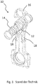
- FIG. 3 shows a plan view of the shaft-hub connection 100 from FIG. 2 ,
- the shaft-hub connection 100 includes a lever 110 having an opening 120 and a bearing member 130 disposed in the opening 120. On both sides of the opening 120, in each case an opening 112, 114 is formed, in which in the normal state of use drawing not executed actuating piston are mounted.
- the opening 120 is designed as a polygonal triangle plan with rounded corners so that the bearing member 130 three contact points 132, 134, 136 between lever 110 and bearing member 130 are formed and between the contact points 132, 134, 136 each have a free space 122, 124, 126th is formed, on which the opening 120 is spaced from the bearing member 130.
- the bearing member 130 has an opening 132 for receiving a conventional piston pin (not shown).
- the free spaces 122, 124, 126 also result in a weight saving of the hub-shaft connection 100.
- the trained as an eccentric bearing member 130 also has a cross-section, which is designed as a polygonal line, for example, with a triangular outline with rounded corners corresponding to the opening 120.
- the deviation from the circular shape is not so strong formed as in the opening 12.
- Small holes 140 in the side region of the bearing member 130 serve to reduce the weight of the bearing member 130th
- the bearing component 130 Before being inserted into the opening 120, the bearing component 130 has a clear width, which at the same temperature of the lever 110 and bearing component 130 is greater than a clear width of the opening 120 for receiving the bearing component 130. It is advantageous to use the intended contact points 132, 134 , 136 of bearing member 130 and lever 110, the contour of opening 120 and bearing member 130 is the same.
- the shaft-hub connection 100 allows easy installation. To insert the bearing component 130 into the opening 120, a temperature difference between the two connection partners is produced in such a way that the bearing component 130 shrinks with respect to the opening 120. If the temperatures of the two connection partners, lever 110 and bearing component 130, match again to one another, the bearing component 130 expands and is pressed firmly into the opening 120.
Description
- Die Erfindung betrifft eine Welle-Nabe-Verbindung mit einem Hebel und einem in eine Öffnung des Hebels eingesetzten Lagerbauteil sowie ein Pleuel mit einer Welle-Nabe-Verbindung.
- Bei Brennkraftmaschinen wirkt sich ein hohes Verdichtungsverhältnis positiv auf den Wirkungsgrad des Verbrennungsmotors aus. Unter Verdichtungsverhältnis wird im Allgemeinen das Verhältnis des gesamten Zylinderraumes vor der Verdichtung zum verbliebenen Zylinderraum nach der Verdichtung verstanden. Bei Brennkraftmaschinen mit Fremdzündung, insbesondere Ottomotoren, die ein festes Verdichtungsverhältnis aufweisen, darf das Verdichtungsverhältnis jedoch nur so hoch gewählt werden, dass bei Volllastbetrieb ein sogenanntes "Klopfen" der Brennkraftmaschine vermieden wird. Jedoch könnte für den weitaus häufiger auftretenden Teillastbereich der Brennkraftmaschine, also bei geringer Zylinderfüllung, das Verdichtungsverhältnis mit höheren Werten gewählt werden, ohne dass ein "Klopfen" auftreten würde. Der wichtige Teillastbereich einer Brennkraftmaschine kann verbessert werden, wenn das Verdichtungsverhältnis variabel einstellbar ist. Zur Verstellung des Verdichtungsverhältnisses sind beispielsweise Systeme mit variabler Pleuellänge bekannt.
- Aus der
DE 10 2005 055 199 A1 ist ein Pleuel bekannt, bei dem im kleinen Pleuelauge ein schwenkbarer Hebel eingesetzt ist, in dessen zentraler Öffnung ein Exzenter eingesetzt ist. Der Exzenter dient zur Aufnahme eines Kolbenbolzens. Der Hebel bildet mit dem Exzenter eine Welle-Nabe-Verbindung, wobei beide Bauteile eine Zahnreihe aufweisen und somit Hebel und Exzenter durch eine Verzahnung verbunden sind. Da die Verbindung im Betrieb des Pleuels hoch belastet wird, sind die Anforderungen an die Fertigungstoleranzen der Verbindungspartner hoch. Aus derWO 92 / 16763 A1 - Eine Aufgabe der Erfindung ist es, ein Pleuel mit einer hochbelastbaren Welle-Nabe-Verbindung mit wenig Spiel zwischen den Verbindungspartnern zu schaffen.
- Die vorgenannte Aufgabe wird mit den Merkmalen des unabhängigen Anspruchs gelöst.
- Günstige Ausgestaltungen und Vorteile der Erfindung ergeben sich aus den weiteren Ansprüchen, der Beschreibung und der Zeichnung.
Es wird eine Welle-Nabe-Verbindung mit einem Hebel und einem in einer Öffnung des Hebels angeordneten Lagerbauteil eines Pleuels vorgeschlagen, wobei die Öffnung so ausgestaltet ist, dass wenigstens drei Kontaktstellen zwischen Hebel und Lagerbauteil ausgebildet sind und zwischen jeweils zwei Kontaktstellen ein Freiraum ausgebildet ist, an dem die Öffnung vom Lagerbauteil gezielt beabstandet ist.
Gezielt beabstandet bedeutet, dass der Grundriss der Öffnung des Hebels, die das Lagerbauteil aufnehmen soll, in den beabstandeten Bereichen größer ist als der Grundriss des Lagerbauteils. Vorteilhaft ist die Verbindung spielfrei und weist gute dynamische Eigenschaften auf und ermöglicht eine Übertragung von hohen Drehmomenten. Im Vergleich zu einer Verzahnung, bei der an beiden Verbindungspartnern jeweils eine Zahnreihe ausgebildet werden muss, ist die Verbindung erheblich weniger aufwändig herzustellen. Die Montage von Hebel und Lagerbauteil ist vereinfacht. Das Lagerbauteil ist ein Exzenter, in dem beim Einbau in eine Brennkraftmaschine ein Kolbenbolzen aufgenommen werden soll. - Die Öffnung ist als nicht kreisrunder Polygonzug ausgebildet. Vorteilhaft sind benachbarte Streckenabschnitte durch einen Punkt mit einem Richtungswechsel von einem zum anderen Streckenabschnitt getrennt. Die Öffnung kann grundsätzlich einen beliebigen Grundriss aufweisen. Es kann eine für den Grundriss des Hebels günstige Kontur gewählt werden, die Anforderungen an den Platzbedarf für die Verbindung und an die Festigkeit des Hebels Rechnung tragen kann. Durch die Wahl eines geeigneten Polygonzugs kann Verbindung raumsparend und dynamisch belastbar ausgeführt werden. Auch kann eine Selbstzentrierung der beiden Verbindungspartner erreicht werden.
Nach einer günstigen Ausgestaltung kann die Öffnung einen Dreiecksgrundriss aufweisen, insbesondere einen Dreiecksgrundriss mit gerundeten Ecken. Dabei können die Linien, welche die Ecken verbinden, gekrümmt sein. Durch die Wahl einer geeigneten Platzierung im Grundriss des Hebels kann die Verbindung besonders raumsparend ausgeführt werden. Die Stabilität des Hebels wird nicht geschwächt. Nach einer günstigen Ausgestaltung kann das Lagerbauteil eine als Polygonzug ausgebildete Außenseite aufweisen. Vorteilhaft kann das Lagerbauteil eine Grundrissart aufweisen, die vergleichbar mit der der Öffnung ist. Dies erlaubt eine besonders genaue Positionierung des Lagerbauteils und Selbstzentrierung der beiden Verbindungspartner. Es kann an den Kontaktstellen ein Formschluss erreicht werden. Die Verbindung ist noch stabiler und belastbarer.
Nach einer günstigen Ausgestaltung kann das Lagerbauteil einen Dreiecksgrundriss aufweisen, insbesondere einen Dreiecksgrundriss mit gerundeten Ecken. Dabei können die Linien, welche die Ecken verbinden, gekrümmt sein. Dies erlaubt eine besonders genaue Selbstzentrierung der beiden Verbindungspartner. Es kann an den Kontaktstellen ein Formschluss erreicht werden. Die Verbindung ist noch stabiler und belastbarer.
Nach einer günstigen Ausgestaltung kann das Lagerbauteil vor dem Einsetzen in die Öffnung einen lichten Außendurchmesser aufweisen, der bei gleicher Temperatur von Hebel und Lagerbauteil größer ist als eine lichte Weite der Öffnung zur Aufnahme des Lagerbauteils. Die Verbindung kann spielfrei hergestellt werden.
Nach einer günstigen Ausgestaltung kann das Lagerbauteil in die Öffnung eingeschrumpft ist. Die Verbindungspartner werden verpresst. Die Verbindung weist eine vorteilhaft geringe Kerbwirkung auf. Durch den Kraftschluss zwischen den Verbindungspartnern ist die Verbindung spielfrei, und es können hohe Drehmomente übertragen werden. Dabei kann das Lagerbauteil abgekühlt werden, so dass dessen Durchmesser schrumpft und in den wärmeren Hebel eingeschoben werden. Bei der anschließenden Erwärmung expandiert das Lagerbauteil und verspannt sich in der Öffnung sicher gegen den Hebel.
Nach einer günstigen Ausgestaltung kann das Lagerbauteil eine geschliffene Außenfläche aufweisen. Die Außenfläche kann mit hoher Qualität und Formtreue hergestellt werden.
Nach einer günstigen Ausgestaltung kann das Lagerbauteil aus einem hochfesten Stahl gebildet sein. - Die Herstellung des Pleuels ist durch die vereinfachte und verbesserte Welle-Nabe-Verbindung von Hebel und Lagerbauteil kostengünstiger bei verbesserter Qualität der Verbindung.
- Weitere Vorteile ergeben sich aus der folgenden Zeichnungsbeschreibung. In den Zeichnungen sind Ausführungsbeispiele der Erfindung dargestellt. Die Zeichnungen, die Beschreibung und die Ansprüche enthalten zahlreiche Merkmale in Kombination. Der Fachmann wird die Merkmale zweckmäßigerweise auch einzeln betrachten und zu sinnvollen weiteren Kombinationen zusammenfassen.
-
- Fig. 1
- in Explosionsdarstellung eine Welle-Nabe-Verbindung bei einem Pleuel nach dem Stand der Technik;
- Fig. 2
- eine Welle-Nabe-Verbindung nach einem Ausführungsbeispiel der Erfindung; und
- Fig. 3
- ein Detail der Welle-Nabe-Verbindung aus
Figur 2 in Draufsicht. - In den Figuren sind gleiche oder gleichartige Komponenten mit gleichen Bezugszeichen beziffert. Die Figuren zeigen lediglich Beispiele und sind nicht beschränkend zu verstehen.
- Das bekannte Pleuel 10 in
Figur 1 weist ein oberes Pleuellagerauge 12 auf, das zur Aufnahme eines nicht dargestellten Kolbenbolzens vorgesehen ist. Dieser Kolbenbolzen ist in üblicher Weise fest in einen Brennraumkolben des Verbrennungsmotors eingesteckt. Das obere Pleuellagerauge 12 ist durch eine Pleuelstange von dem in der Figur unteren, großen Pleuellagerauge getrennt. - Das obere Pleuellagerauge 12 ist mittels eines als Exzenter 14 ausgebildeten Lagerbauteils um eine Schwenkachse schwenkbar, die parallel versetzt zur Längsachse des oberen Pleuellagerauges 12 liegt. Dazu ist der Exzenter 14 in eine Öffnung 12 eines Hebels 16 eingesetzt. Zur Herstellung einer möglichst spielfreien Verbindung weisen sowohl der Hebel 16 eine innere Zahnreihe als auch der Exzenter 14 eine äußere Zahnreihe auf, die ineinander greifen. Somit ist es möglich, das obere Pleuellagerauge 12 in seinem Abstand zu einer Pleuellagerachse des in der Figur unteren Pleuellagerauges zu verändern und über die am oberen Pleuellagerauge 12 gelagerten Stellkolben 18 eine variable Verdichtung im Brennraum zu verwirklichen.
-
Figur 2 zeigt eine perspektivische Ansicht einer Welle-Nabe-Verbindung 100 nach einem Ausführungsbeispiel der Erfindung, undFigur 3 zeigt eine Draufsicht auf die Welle-Nabe-Verbindung 100 ausFigur 2 . - Die Welle-Nabe-Verbindung 100 umfasst einen Hebel 110 mit einer Öffnung 120 und ein Lagerbauteil 130, das in der Öffnung 120 angeordnet ist. Beidseits der Öffnung 120 ist jeweils eine Öffnung 112, 114 ausgebildet, in denen im normalen Gebrauchszustand zeichnerisch nicht ausgeführte Stellkolben gelagert sind.
- Die Öffnung 120 ist als Polygonzug mit Dreiecksgrundriss mit gerundeten Ecken so ausgestaltet, dass das Lagerbauteil 130 drei Kontaktstellen 132, 134, 136 zwischen Hebel 110 und Lagerbauteil 130 ausbildet sind und zwischen den Kontaktstellen 132, 134, 136 jeweils ein Freiraum 122, 124, 126 ausgebildet ist, an dem die Öffnung 120 vom Lagerbauteil 130 beabstandet ist. Das Lagerbauteil 130 weist eine Öffnung 132 zur Aufnahme eines üblichen Kolbenbolzens auf (nicht dargestellt). Die Freiräume 122, 124, 126 ergeben auch eine Gewichtsersparnis der Nabe-Welle-Verbindung 100.
- Das als Exzenter ausgebildete Lagerbauteil 130 weist ebenfalls einen Querschnitt auf, der als Polygonzug ausgebildet ist, z.B. mit Dreiecksgrundriss mit gerundeten Ecken entsprechend der Öffnung 120. Die Abweichung von der Kreisform ist nicht so stark ausgebildet wie bei der Öffnung 12. Kleine Bohrungen 140 im Seitenbereich des Lagerbauteils 130 dienen der Gewichtsreduzierung des Lagerbauteils 130.
- Das Lagerbauteil 130 weist vor dem Einsetzen in die Öffnung 120 eine lichte Weite auf, die bei gleicher Temperatur von Hebel 110 und Lagerbauteil 130 größer ist als eine lichte Weite der Öffnung 120 zur Aufnahme des Lagerbauteils 130. Vorteilhaft ist an den vorgesehenen Kontaktstellen 132, 134, 136 von Lagerbauteil 130 und Hebel 110 die Kontur von Öffnung 120 und Lagerbauteil 130 gleich.
- Die Welle-Nabe-Verbindung 100 erlaubt eine einfache Montage. Zum Einsetzen des Lagerbauteils 130 in die Öffnung 120 wird eine Temperaturdifferenz zwischen den beiden Verbindungspartnern hergestellt dergestalt, dass das Lagerbauteil 130 gegenüber der Öffnung 120 schrumpft. Gleichen sich die Temperaturen der beiden Verbindungspartner Hebel 110 und Lagerbauteil 130 wieder aneinander an, expandiert das Lagerbauteil 130 und wird fest in die Öffnung 120 eingepresst.
- Durch die Polygonzug-Außenkontur des Lagerbauteils 130 und dem Polygonzug der Öffnung 120 stellt sich ein vorteilhafter selbstzentrierender Formschluss und Kraftschluss mit sehr geringer Kerbwirkung ein. Mit der Welle-Nabe-Verbindung 100 können sehr hohe Drehmomente bei guten dynamischen Eigenschaften übertragen werden.
Claims (7)
- Pleuel (200) mit einer variablen Pleuellänge für eine Brennkraftmaschine mit variabler Verdichtung umfassend eine Welle-Nabe-Verbindung (100) mit einem Hebel (110) und einem in einer Öffnung (120) des Hebels (110) angeordneten, als Exzenter ausgebildeten Lagerbauteil (130) des Pleuels (200), dadurch gekennzeichnet, dass die Öffnung (120) so ausgestaltet ist, dass drei Kontaktstellen (132, 134, 136) zwischen Hebel (110) und Lagerbauteil (130) ausgebildet sind und zwischen jeweils zwei Kontaktstellen (132, 134, 136) ein Freiraum (122, 124, 126) ausgebildet ist, an dem die Öffnung (120) vom Lagerbauteil (130) gezielt beabstandet ist, wobei die Öffnung (120) als Polygonzug ausgebildet ist und das Lagerbauteil (130) eine als Polygonzug ausgebildete Außenseite aufweist, wobei der Polygonzug der Außenseite des Lagerteils (130) weniger von einer Kreisform abweicht als der Polygonzug der Öffnung (120) .
- Pleuel (200) nach Anspruch 1, dadurch gekennzeichnet, dass die Öffnung (120) einen Dreiecksgrundriss aufweist, insbesondere einen Dreiecksgrundriss mit gerundeten Ecken.
- Pleuel (200) nach Anspruch 2, dadurch gekennzeichnet, dass das Lagerbauteil (130) einen Dreiecksgrundriss aufweist, insbesondere einen Dreiecksgrundriss mit gerundeten Ecken.
- Pleuel (200) nach einem der vorhergehenden Ansprüche, wobei dadurch gekennzeichnet, dass das Lagerbauteil (130) vor dem Einsetzen in die Öffnung (120) einen Außendurchmesser aufweist, der bei gleicher Temperatur von Hebel (110) und Lagerbauteil (130) größer ist als eine lichte Weite der Öffnung (120) zur Aufnahme des Lagerbauteils (130).
- Pleuel (200) nach einem der vorhergehenden Ansprüche, dadurch gekennzeichnet, dass das Lagerbauteil (130) in die Öffnung (120) eingeschrumpft ist.
- Pleuel (200) nach einem der vorhergehenden Ansprüche, dadurch gekennzeichnet, dass das Lagerbauteil (130) eine geschliffene Außenfläche aufweist.
- Pleuel (200) nach einem der vorhergehenden Ansprüche, dadurch gekennzeichnet, dass das Lagerbauteil (130) aus einem hochfesten Stahl gebildet ist.
Applications Claiming Priority (2)
| Application Number | Priority Date | Filing Date | Title |
|---|---|---|---|
| DE102015104544.3A DE102015104544A1 (de) | 2015-03-25 | 2015-03-25 | Welle-Nabe-Verbindung, insbesondere eines Pleuels |
| PCT/EP2016/051396 WO2016150589A1 (de) | 2015-03-25 | 2016-01-25 | Welle-nabe-verbindung, insbesondere eines pleuels |
Publications (2)
| Publication Number | Publication Date |
|---|---|
| EP3274574A1 EP3274574A1 (de) | 2018-01-31 |
| EP3274574B1 true EP3274574B1 (de) | 2018-12-12 |
Family
ID=55273224
Family Applications (1)
| Application Number | Title | Priority Date | Filing Date |
|---|---|---|---|
| EP16702359.7A Not-in-force EP3274574B1 (de) | 2015-03-25 | 2016-01-25 | Pleuel mit welle-nabe-verbindung |
Country Status (5)
| Country | Link |
|---|---|
| US (1) | US20180023468A1 (de) |
| EP (1) | EP3274574B1 (de) |
| CN (1) | CN107223182B (de) |
| DE (1) | DE102015104544A1 (de) |
| WO (1) | WO2016150589A1 (de) |
Family Cites Families (9)
| Publication number | Priority date | Publication date | Assignee | Title |
|---|---|---|---|---|
| DE4209153C3 (de) * | 1991-03-22 | 1998-10-01 | Hans Kuehl | Welle-Nabe-Verbindung |
| US5343618A (en) * | 1991-09-03 | 1994-09-06 | General Motors Corporation | Method of assembling a shaft and apertured member |
| EP0530890B1 (de) * | 1991-09-03 | 1995-06-14 | General Motors Corporation | Gebaute Welle und Verfahren zu ihrer Herstellung |
| DE4130031C2 (de) * | 1991-09-10 | 1994-09-01 | Graebener Theodor Pressensyst | Hub-Verstellvorrichtung für Exzenterwellen, insbesondere zum Antrieb von Exzenterpressen |
| DE102005055199B4 (de) | 2005-11-19 | 2019-01-31 | FEV Europe GmbH | Hubkolbenverbrennungskraftmaschine mit einstellbar veränderbarem Verdichtungsverhältnis |
| US20150377100A1 (en) * | 2013-02-25 | 2015-12-31 | Shiloh Industries, Inc. | Modular Assembly Having Press-Fit Fastener Holes |
| DE202013004236U1 (de) * | 2013-05-04 | 2013-07-10 | Gkn Driveline International Gmbh | Welle-Nabe-Verbindung |
| DE102013211936A1 (de) * | 2013-06-24 | 2014-12-24 | Mahle International Gmbh | Welle-Nabe-Verbindung |
| DE102013014090A1 (de) * | 2013-08-27 | 2015-03-05 | Dr. Ing. H.C. F. Porsche Ag | Verbrennungsmotor und Pleuelstange |
-
2015
- 2015-03-25 DE DE102015104544.3A patent/DE102015104544A1/de not_active Withdrawn
-
2016
- 2016-01-25 CN CN201680010142.3A patent/CN107223182B/zh not_active Expired - Fee Related
- 2016-01-25 EP EP16702359.7A patent/EP3274574B1/de not_active Not-in-force
- 2016-01-25 WO PCT/EP2016/051396 patent/WO2016150589A1/de active Application Filing
-
2017
- 2017-09-03 US US15/694,816 patent/US20180023468A1/en not_active Abandoned
Non-Patent Citations (1)
| Title |
|---|
| None * |
Also Published As
| Publication number | Publication date |
|---|---|
| CN107223182A (zh) | 2017-09-29 |
| CN107223182B (zh) | 2019-11-08 |
| US20180023468A1 (en) | 2018-01-25 |
| EP3274574A1 (de) | 2018-01-31 |
| WO2016150589A1 (de) | 2016-09-29 |
| DE102015104544A1 (de) | 2016-09-29 |
Similar Documents
| Publication | Publication Date | Title |
|---|---|---|
| EP3067576A1 (de) | Kugelgelenk, insbesondere pleuelkugelgelenk, sowie pleuel mit einem kugelgelenk | |
| EP3096025A1 (de) | Kupplung bestehend aus kupplungsbolzen und halter sowie ein verfahren zum verbinden eines ersten und zweiten bauteils mithilfe der kupplung | |
| DE102012111124B3 (de) | Gebaute Kurbelwelle sowie Verfahren zur Herstellung einer gebauten Kurbelwelle | |
| DE102016112539A1 (de) | Geteilte Lageranordnung | |
| EP3268641B1 (de) | Pleuel mit einem kugelgelenk | |
| AT519652A4 (de) | Dichtungsvorrichtung und Hydraulikkolben mit Dichtungsvorrichtung | |
| WO2016169670A1 (de) | Einleger und pleuel für eine variable verdichtung einer brennkraftmaschine | |
| EP1920174B1 (de) | Verlaufende bolzenbohrungsgeometrie für einen kolben einer brennkraftmaschine | |
| EP3274574B1 (de) | Pleuel mit welle-nabe-verbindung | |
| WO2017016934A1 (de) | Kolben für einen verbrennungsmotor | |
| EP3347627B1 (de) | Kombination eines kolbens und eines pleuels | |
| WO2011012625A1 (de) | Pleuel | |
| WO2018041880A1 (de) | Kolben, bestehend aus einem innenteil und einem aussenteil | |
| WO2017076920A1 (de) | Optimierte nabenabstützung | |
| DE102017201602B4 (de) | Ausgleichswelle | |
| DE102014222416A1 (de) | Kolben für eine Brennkraftmaschine | |
| DE102014112808B4 (de) | Anordnung eines Nockenwellen-Steller-Rotors eines Nockenwellen-Stellers an einem Abschnitt einer Nockenwelle sowie Verfahren zur Herstellung eines Nockenwellen-Steller-Rotors und eines Abschnitts einer Nockenwelle für eine solche Anordnung | |
| AT522190B1 (de) | Lagerdeckel | |
| DE102012203621A1 (de) | Kraftstoffinjektor | |
| DE102017112895B4 (de) | Ausgleichswelle und Ausgleichswellenbaugruppe | |
| WO2004005678A1 (de) | Elektromagnetisches hydraulikventil, insbesondere proportionalventil zur steuerung einer vorrichtung zur drehwinkelverstellung einer nockenwelle gegenüber einer kurbelwelle einer brennkraftmaschine | |
| EP3008318A1 (de) | Gleitschuh für einen kolben zum einsatz in brennkraftmaschinen | |
| DE10354076B4 (de) | Leichtbauventil | |
| DE102019103381A1 (de) | Gebaute Kurbelwelle für eine Hubkolben-Brennkraftmaschine | |
| DE3714400A1 (de) | Kolben fuer brennkraftmaschinen |
Legal Events
| Date | Code | Title | Description |
|---|---|---|---|
| STAA | Information on the status of an ep patent application or granted ep patent |
Free format text: STATUS: THE INTERNATIONAL PUBLICATION HAS BEEN MADE |
|
| PUAI | Public reference made under article 153(3) epc to a published international application that has entered the european phase |
Free format text: ORIGINAL CODE: 0009012 |
|
| STAA | Information on the status of an ep patent application or granted ep patent |
Free format text: STATUS: REQUEST FOR EXAMINATION WAS MADE |
|
| 17P | Request for examination filed |
Effective date: 20170904 |
|
| AK | Designated contracting states |
Kind code of ref document: A1 Designated state(s): AL AT BE BG CH CY CZ DE DK EE ES FI FR GB GR HR HU IE IS IT LI LT LU LV MC MK MT NL NO PL PT RO RS SE SI SK SM TR |
|
| AX | Request for extension of the european patent |
Extension state: BA ME |
|
| DAV | Request for validation of the european patent (deleted) | ||
| DAX | Request for extension of the european patent (deleted) | ||
| GRAP | Despatch of communication of intention to grant a patent |
Free format text: ORIGINAL CODE: EPIDOSNIGR1 |
|
| STAA | Information on the status of an ep patent application or granted ep patent |
Free format text: STATUS: GRANT OF PATENT IS INTENDED |
|
| GRAS | Grant fee paid |
Free format text: ORIGINAL CODE: EPIDOSNIGR3 |
|
| INTG | Intention to grant announced |
Effective date: 20180925 |
|
| GRAA | (expected) grant |
Free format text: ORIGINAL CODE: 0009210 |
|
| STAA | Information on the status of an ep patent application or granted ep patent |
Free format text: STATUS: THE PATENT HAS BEEN GRANTED |
|
| AK | Designated contracting states |
Kind code of ref document: B1 Designated state(s): AL AT BE BG CH CY CZ DE DK EE ES FI FR GB GR HR HU IE IS IT LI LT LU LV MC MK MT NL NO PL PT RO RS SE SI SK SM TR |
|
| REG | Reference to a national code |
Ref country code: GB Ref legal event code: FG4D Free format text: NOT ENGLISH |
|
| REG | Reference to a national code |
Ref country code: CH Ref legal event code: EP |
|
| REG | Reference to a national code |
Ref country code: AT Ref legal event code: REF Ref document number: 1076293 Country of ref document: AT Kind code of ref document: T Effective date: 20181215 |
|
| REG | Reference to a national code |
Ref country code: DE Ref legal event code: R096 Ref document number: 502016002836 Country of ref document: DE |
|
| REG | Reference to a national code |
Ref country code: IE Ref legal event code: FG4D Free format text: LANGUAGE OF EP DOCUMENT: GERMAN |
|
| REG | Reference to a national code |
Ref country code: NL Ref legal event code: MP Effective date: 20181212 |
|
| REG | Reference to a national code |
Ref country code: LT Ref legal event code: MG4D |
|
| PG25 | Lapsed in a contracting state [announced via postgrant information from national office to epo] |
Ref country code: ES Free format text: LAPSE BECAUSE OF FAILURE TO SUBMIT A TRANSLATION OF THE DESCRIPTION OR TO PAY THE FEE WITHIN THE PRESCRIBED TIME-LIMIT Effective date: 20181212 Ref country code: BG Free format text: LAPSE BECAUSE OF FAILURE TO SUBMIT A TRANSLATION OF THE DESCRIPTION OR TO PAY THE FEE WITHIN THE PRESCRIBED TIME-LIMIT Effective date: 20190312 Ref country code: LT Free format text: LAPSE BECAUSE OF FAILURE TO SUBMIT A TRANSLATION OF THE DESCRIPTION OR TO PAY THE FEE WITHIN THE PRESCRIBED TIME-LIMIT Effective date: 20181212 Ref country code: HR Free format text: LAPSE BECAUSE OF FAILURE TO SUBMIT A TRANSLATION OF THE DESCRIPTION OR TO PAY THE FEE WITHIN THE PRESCRIBED TIME-LIMIT Effective date: 20181212 Ref country code: LV Free format text: LAPSE BECAUSE OF FAILURE TO SUBMIT A TRANSLATION OF THE DESCRIPTION OR TO PAY THE FEE WITHIN THE PRESCRIBED TIME-LIMIT Effective date: 20181212 Ref country code: NO Free format text: LAPSE BECAUSE OF FAILURE TO SUBMIT A TRANSLATION OF THE DESCRIPTION OR TO PAY THE FEE WITHIN THE PRESCRIBED TIME-LIMIT Effective date: 20190312 Ref country code: FI Free format text: LAPSE BECAUSE OF FAILURE TO SUBMIT A TRANSLATION OF THE DESCRIPTION OR TO PAY THE FEE WITHIN THE PRESCRIBED TIME-LIMIT Effective date: 20181212 |
|
| PG25 | Lapsed in a contracting state [announced via postgrant information from national office to epo] |
Ref country code: AL Free format text: LAPSE BECAUSE OF FAILURE TO SUBMIT A TRANSLATION OF THE DESCRIPTION OR TO PAY THE FEE WITHIN THE PRESCRIBED TIME-LIMIT Effective date: 20181212 Ref country code: SE Free format text: LAPSE BECAUSE OF FAILURE TO SUBMIT A TRANSLATION OF THE DESCRIPTION OR TO PAY THE FEE WITHIN THE PRESCRIBED TIME-LIMIT Effective date: 20181212 Ref country code: GR Free format text: LAPSE BECAUSE OF FAILURE TO SUBMIT A TRANSLATION OF THE DESCRIPTION OR TO PAY THE FEE WITHIN THE PRESCRIBED TIME-LIMIT Effective date: 20190313 Ref country code: RS Free format text: LAPSE BECAUSE OF FAILURE TO SUBMIT A TRANSLATION OF THE DESCRIPTION OR TO PAY THE FEE WITHIN THE PRESCRIBED TIME-LIMIT Effective date: 20181212 |
|
| PG25 | Lapsed in a contracting state [announced via postgrant information from national office to epo] |
Ref country code: NL Free format text: LAPSE BECAUSE OF FAILURE TO SUBMIT A TRANSLATION OF THE DESCRIPTION OR TO PAY THE FEE WITHIN THE PRESCRIBED TIME-LIMIT Effective date: 20181212 |
|
| PG25 | Lapsed in a contracting state [announced via postgrant information from national office to epo] |
Ref country code: CZ Free format text: LAPSE BECAUSE OF FAILURE TO SUBMIT A TRANSLATION OF THE DESCRIPTION OR TO PAY THE FEE WITHIN THE PRESCRIBED TIME-LIMIT Effective date: 20181212 Ref country code: PT Free format text: LAPSE BECAUSE OF FAILURE TO SUBMIT A TRANSLATION OF THE DESCRIPTION OR TO PAY THE FEE WITHIN THE PRESCRIBED TIME-LIMIT Effective date: 20190412 Ref country code: IT Free format text: LAPSE BECAUSE OF FAILURE TO SUBMIT A TRANSLATION OF THE DESCRIPTION OR TO PAY THE FEE WITHIN THE PRESCRIBED TIME-LIMIT Effective date: 20181212 Ref country code: PL Free format text: LAPSE BECAUSE OF FAILURE TO SUBMIT A TRANSLATION OF THE DESCRIPTION OR TO PAY THE FEE WITHIN THE PRESCRIBED TIME-LIMIT Effective date: 20181212 |
|
| PG25 | Lapsed in a contracting state [announced via postgrant information from national office to epo] |
Ref country code: SK Free format text: LAPSE BECAUSE OF FAILURE TO SUBMIT A TRANSLATION OF THE DESCRIPTION OR TO PAY THE FEE WITHIN THE PRESCRIBED TIME-LIMIT Effective date: 20181212 Ref country code: RO Free format text: LAPSE BECAUSE OF FAILURE TO SUBMIT A TRANSLATION OF THE DESCRIPTION OR TO PAY THE FEE WITHIN THE PRESCRIBED TIME-LIMIT Effective date: 20181212 Ref country code: IS Free format text: LAPSE BECAUSE OF FAILURE TO SUBMIT A TRANSLATION OF THE DESCRIPTION OR TO PAY THE FEE WITHIN THE PRESCRIBED TIME-LIMIT Effective date: 20190412 Ref country code: EE Free format text: LAPSE BECAUSE OF FAILURE TO SUBMIT A TRANSLATION OF THE DESCRIPTION OR TO PAY THE FEE WITHIN THE PRESCRIBED TIME-LIMIT Effective date: 20181212 Ref country code: SM Free format text: LAPSE BECAUSE OF FAILURE TO SUBMIT A TRANSLATION OF THE DESCRIPTION OR TO PAY THE FEE WITHIN THE PRESCRIBED TIME-LIMIT Effective date: 20181212 |
|
| REG | Reference to a national code |
Ref country code: CH Ref legal event code: PL |
|
| REG | Reference to a national code |
Ref country code: DE Ref legal event code: R097 Ref document number: 502016002836 Country of ref document: DE |
|
| PG25 | Lapsed in a contracting state [announced via postgrant information from national office to epo] |
Ref country code: LU Free format text: LAPSE BECAUSE OF NON-PAYMENT OF DUE FEES Effective date: 20190125 |
|
| REG | Reference to a national code |
Ref country code: BE Ref legal event code: MM Effective date: 20190131 |
|
| PLBE | No opposition filed within time limit |
Free format text: ORIGINAL CODE: 0009261 |
|
| STAA | Information on the status of an ep patent application or granted ep patent |
Free format text: STATUS: NO OPPOSITION FILED WITHIN TIME LIMIT |
|
| REG | Reference to a national code |
Ref country code: IE Ref legal event code: MM4A |
|
| PG25 | Lapsed in a contracting state [announced via postgrant information from national office to epo] |
Ref country code: DK Free format text: LAPSE BECAUSE OF FAILURE TO SUBMIT A TRANSLATION OF THE DESCRIPTION OR TO PAY THE FEE WITHIN THE PRESCRIBED TIME-LIMIT Effective date: 20181212 Ref country code: MC Free format text: LAPSE BECAUSE OF FAILURE TO SUBMIT A TRANSLATION OF THE DESCRIPTION OR TO PAY THE FEE WITHIN THE PRESCRIBED TIME-LIMIT Effective date: 20181212 |
|
| 26N | No opposition filed |
Effective date: 20190913 |
|
| PG25 | Lapsed in a contracting state [announced via postgrant information from national office to epo] |
Ref country code: BE Free format text: LAPSE BECAUSE OF NON-PAYMENT OF DUE FEES Effective date: 20190131 |
|
| PG25 | Lapsed in a contracting state [announced via postgrant information from national office to epo] |
Ref country code: CH Free format text: LAPSE BECAUSE OF NON-PAYMENT OF DUE FEES Effective date: 20190131 Ref country code: LI Free format text: LAPSE BECAUSE OF NON-PAYMENT OF DUE FEES Effective date: 20190131 |
|
| PG25 | Lapsed in a contracting state [announced via postgrant information from national office to epo] |
Ref country code: IE Free format text: LAPSE BECAUSE OF NON-PAYMENT OF DUE FEES Effective date: 20190125 |
|
| PG25 | Lapsed in a contracting state [announced via postgrant information from national office to epo] |
Ref country code: TR Free format text: LAPSE BECAUSE OF FAILURE TO SUBMIT A TRANSLATION OF THE DESCRIPTION OR TO PAY THE FEE WITHIN THE PRESCRIBED TIME-LIMIT Effective date: 20181212 |
|
| PG25 | Lapsed in a contracting state [announced via postgrant information from national office to epo] |
Ref country code: MT Free format text: LAPSE BECAUSE OF FAILURE TO SUBMIT A TRANSLATION OF THE DESCRIPTION OR TO PAY THE FEE WITHIN THE PRESCRIBED TIME-LIMIT Effective date: 20181212 |
|
| GBPC | Gb: european patent ceased through non-payment of renewal fee |
Effective date: 20200125 |
|
| PG25 | Lapsed in a contracting state [announced via postgrant information from national office to epo] |
Ref country code: GB Free format text: LAPSE BECAUSE OF NON-PAYMENT OF DUE FEES Effective date: 20200125 |
|
| PG25 | Lapsed in a contracting state [announced via postgrant information from national office to epo] |
Ref country code: CY Free format text: LAPSE BECAUSE OF FAILURE TO SUBMIT A TRANSLATION OF THE DESCRIPTION OR TO PAY THE FEE WITHIN THE PRESCRIBED TIME-LIMIT Effective date: 20181212 |
|
| PG25 | Lapsed in a contracting state [announced via postgrant information from national office to epo] |
Ref country code: HU Free format text: LAPSE BECAUSE OF FAILURE TO SUBMIT A TRANSLATION OF THE DESCRIPTION OR TO PAY THE FEE WITHIN THE PRESCRIBED TIME-LIMIT; INVALID AB INITIO Effective date: 20160125 |
|
| PG25 | Lapsed in a contracting state [announced via postgrant information from national office to epo] |
Ref country code: SI Free format text: LAPSE BECAUSE OF FAILURE TO SUBMIT A TRANSLATION OF THE DESCRIPTION OR TO PAY THE FEE WITHIN THE PRESCRIBED TIME-LIMIT Effective date: 20181212 |
|
| REG | Reference to a national code |
Ref country code: AT Ref legal event code: MM01 Ref document number: 1076293 Country of ref document: AT Kind code of ref document: T Effective date: 20210125 |
|
| PG25 | Lapsed in a contracting state [announced via postgrant information from national office to epo] |
Ref country code: AT Free format text: LAPSE BECAUSE OF NON-PAYMENT OF DUE FEES Effective date: 20210125 |
|
| PGFP | Annual fee paid to national office [announced via postgrant information from national office to epo] |
Ref country code: DE Payment date: 20220119 Year of fee payment: 7 |
|
| PGFP | Annual fee paid to national office [announced via postgrant information from national office to epo] |
Ref country code: FR Payment date: 20220119 Year of fee payment: 7 |
|
| PG25 | Lapsed in a contracting state [announced via postgrant information from national office to epo] |
Ref country code: MK Free format text: LAPSE BECAUSE OF FAILURE TO SUBMIT A TRANSLATION OF THE DESCRIPTION OR TO PAY THE FEE WITHIN THE PRESCRIBED TIME-LIMIT Effective date: 20181212 |
|
| REG | Reference to a national code |
Ref country code: DE Ref legal event code: R119 Ref document number: 502016002836 Country of ref document: DE |
|
| PG25 | Lapsed in a contracting state [announced via postgrant information from national office to epo] |
Ref country code: DE Free format text: LAPSE BECAUSE OF NON-PAYMENT OF DUE FEES Effective date: 20230801 |
|
| PG25 | Lapsed in a contracting state [announced via postgrant information from national office to epo] |
Ref country code: FR Free format text: LAPSE BECAUSE OF NON-PAYMENT OF DUE FEES Effective date: 20230131 |