EP3273850B1 - Optical vital signs sensor - Google Patents
Optical vital signs sensor Download PDFInfo
- Publication number
- EP3273850B1 EP3273850B1 EP16714251.2A EP16714251A EP3273850B1 EP 3273850 B1 EP3273850 B1 EP 3273850B1 EP 16714251 A EP16714251 A EP 16714251A EP 3273850 B1 EP3273850 B1 EP 3273850B1
- Authority
- EP
- European Patent Office
- Prior art keywords
- light
- vital signs
- color converting
- converting plate
- user
- Prior art date
- Legal status (The legal status is an assumption and is not a legal conclusion. Google has not performed a legal analysis and makes no representation as to the accuracy of the status listed.)
- Active
Links
Images


Classifications
-
- A—HUMAN NECESSITIES
- A61—MEDICAL OR VETERINARY SCIENCE; HYGIENE
- A61B—DIAGNOSIS; SURGERY; IDENTIFICATION
- A61B5/00—Measuring for diagnostic purposes; Identification of persons
- A61B5/02—Detecting, measuring or recording for evaluating the cardiovascular system, e.g. pulse, heart rate, blood pressure or blood flow
- A61B5/024—Measuring pulse rate or heart rate
- A61B5/02416—Measuring pulse rate or heart rate using photoplethysmograph signals, e.g. generated by infrared radiation
- A61B5/02427—Details of sensor
-
- A—HUMAN NECESSITIES
- A61—MEDICAL OR VETERINARY SCIENCE; HYGIENE
- A61B—DIAGNOSIS; SURGERY; IDENTIFICATION
- A61B5/00—Measuring for diagnostic purposes; Identification of persons
- A61B5/02—Detecting, measuring or recording for evaluating the cardiovascular system, e.g. pulse, heart rate, blood pressure or blood flow
- A61B5/026—Measuring blood flow
- A61B5/0261—Measuring blood flow using optical means, e.g. infrared light
-
- A—HUMAN NECESSITIES
- A61—MEDICAL OR VETERINARY SCIENCE; HYGIENE
- A61B—DIAGNOSIS; SURGERY; IDENTIFICATION
- A61B5/00—Measuring for diagnostic purposes; Identification of persons
- A61B5/145—Measuring characteristics of blood in vivo, e.g. gas concentration or pH-value ; Measuring characteristics of body fluids or tissues, e.g. interstitial fluid or cerebral tissue
- A61B5/1455—Measuring characteristics of blood in vivo, e.g. gas concentration or pH-value ; Measuring characteristics of body fluids or tissues, e.g. interstitial fluid or cerebral tissue using optical sensors, e.g. spectral photometrical oximeters
- A61B5/14551—Measuring characteristics of blood in vivo, e.g. gas concentration or pH-value ; Measuring characteristics of body fluids or tissues, e.g. interstitial fluid or cerebral tissue using optical sensors, e.g. spectral photometrical oximeters for measuring blood gases
- A61B5/14552—Details of sensors specially adapted therefor
-
- A—HUMAN NECESSITIES
- A61—MEDICAL OR VETERINARY SCIENCE; HYGIENE
- A61B—DIAGNOSIS; SURGERY; IDENTIFICATION
- A61B2562/00—Details of sensors; Constructional details of sensor housings or probes; Accessories for sensors
- A61B2562/02—Details of sensors specially adapted for in-vivo measurements
- A61B2562/0233—Special features of optical sensors or probes classified in A61B5/00
- A61B2562/0238—Optical sensor arrangements for performing transmission measurements on body tissue
-
- A—HUMAN NECESSITIES
- A61—MEDICAL OR VETERINARY SCIENCE; HYGIENE
- A61B—DIAGNOSIS; SURGERY; IDENTIFICATION
- A61B5/00—Measuring for diagnostic purposes; Identification of persons
- A61B5/0059—Measuring for diagnostic purposes; Identification of persons using light, e.g. diagnosis by transillumination, diascopy, fluorescence
-
- A—HUMAN NECESSITIES
- A61—MEDICAL OR VETERINARY SCIENCE; HYGIENE
- A61B—DIAGNOSIS; SURGERY; IDENTIFICATION
- A61B5/00—Measuring for diagnostic purposes; Identification of persons
- A61B5/68—Arrangements of detecting, measuring or recording means, e.g. sensors, in relation to patient
- A61B5/6801—Arrangements of detecting, measuring or recording means, e.g. sensors, in relation to patient specially adapted to be attached to or worn on the body surface
- A61B5/6813—Specially adapted to be attached to a specific body part
- A61B5/6824—Arm or wrist
-
- H—ELECTRICITY
- H10—SEMICONDUCTOR DEVICES; ELECTRIC SOLID-STATE DEVICES NOT OTHERWISE PROVIDED FOR
- H10H—INORGANIC LIGHT-EMITTING SEMICONDUCTOR DEVICES HAVING POTENTIAL BARRIERS
- H10H20/00—Individual inorganic light-emitting semiconductor devices having potential barriers, e.g. light-emitting diodes [LED]
- H10H20/80—Constructional details
- H10H20/84—Coatings, e.g. passivation layers or antireflective coatings
-
- H—ELECTRICITY
- H10—SEMICONDUCTOR DEVICES; ELECTRIC SOLID-STATE DEVICES NOT OTHERWISE PROVIDED FOR
- H10H—INORGANIC LIGHT-EMITTING SEMICONDUCTOR DEVICES HAVING POTENTIAL BARRIERS
- H10H20/00—Individual inorganic light-emitting semiconductor devices having potential barriers, e.g. light-emitting diodes [LED]
- H10H20/80—Constructional details
- H10H20/85—Packages
- H10H20/851—Wavelength conversion means
- H10H20/8514—Wavelength conversion means characterised by their shape, e.g. plate or foil
-
- H—ELECTRICITY
- H10—SEMICONDUCTOR DEVICES; ELECTRIC SOLID-STATE DEVICES NOT OTHERWISE PROVIDED FOR
- H10H—INORGANIC LIGHT-EMITTING SEMICONDUCTOR DEVICES HAVING POTENTIAL BARRIERS
- H10H20/00—Individual inorganic light-emitting semiconductor devices having potential barriers, e.g. light-emitting diodes [LED]
- H10H20/80—Constructional details
- H10H20/85—Packages
- H10H20/851—Wavelength conversion means
- H10H20/8515—Wavelength conversion means not being in contact with the bodies
-
- H—ELECTRICITY
- H10—SEMICONDUCTOR DEVICES; ELECTRIC SOLID-STATE DEVICES NOT OTHERWISE PROVIDED FOR
- H10W—GENERIC PACKAGES, INTERCONNECTIONS, CONNECTORS OR OTHER CONSTRUCTIONAL DETAILS OF DEVICES COVERED BY CLASS H10
- H10W90/00—Package configurations
Definitions
- the invention relates to an optical vital signs sensor for monitoring vital signs of a user.
- Optical heart rate sensors are well known to monitor or detect vital signs like a heart rate of a user.
- a heart rate sensor can be based on a photoplethysmograph (PPG) sensor and can be used to acquire a volumetric organ measurement.
- PPG photoplethysmograph
- the PPG sensors comprise a light source like a light emitting diode (LED) which is emitting light into the skin of a user. The emitted light is scattered in the skin and is at least partially absorbed by the blood. Part of the light exits the skin and can be captured by a photodiode.
- LED light emitting diode
- the amount of light that is captured by the photo diode can be an indication of the blood volume inside the skin of a user.
- a PPG sensor can monitor the perfusion of blood in the dermis and subcutaneous tissue of the skin through an absorption measurement at a specific wave length. If the blood volume is changed due to the pulsating heart, the scattered light coming back from the skin of the user is also changing. Therefore, by monitoring the detected light signal by means of the photodiode, a pulse of a user in his skin and thus the heart rate can be determined. Furthermore, compounds of the blood like oxygenated or de-oxygenated hemoglobin as well as oxygen saturation can be determined.
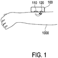
- Fig. 1 shows a basic representation of an operational principle of a heart rate sensor.
- a heart rate sensor is arranged on an arm of a user.
- the heart rate sensor 100 comprises a light source 110 and a photo detector 120.
- the light source 110 emits typically green light onto or in the skin 1000 of a user. Some of the light is reflected and the reflected light can be detected by the photo detector 120. Some light can be transmitted through tissue of the user and be detected by the photo detector 120. Based on the reflected or transmitted light, vital signs of a user like a heart rate can be determined.
- WO 2006/110488 A2 shows a PPG sensor with coupling gel proximate to a light source of the PPG sensor.
- US 2012/0078116 A1 discloses an optical vital signs sensor with a contact surface, a light source and a photo detector as well as a filter adapted to remove part of the light spectrum.
- EP 2 139 383 B1 discloses an optical vital signs sensor with a light source, a photo detector and a filter for removing part of the lights spectrum.
- JP 2001025462 A discloses an optical vital signs sensor with a light source, a photo detector and a filter in form of a coated acrylic board.
- US 2014/0243648 A1 discloses an optical vital signs sensor with a light source, a photo detector and a colored converting plate.
- an optical vital sensor according to claim 1 is provided.
- the diffusion chamber has a recycling function, namely it is re-trying to convert the unconverted light.
- the color converting plate comprises a long-wave pass filter coating or film which is able to transmit light having a long wavelength while reflecting light having short wavelengths.
- the vital signs sensor can be a LED based PPG sensor.
- the LED light penetrates the skin of the user and some of it can reach a photo detector.
- the output of the photo detector can be used to monitor a blood volume fraction and blood compounds like oxygenated and de-oxygenated hemoglobin.
- the amount of absorption or reflectance of the light from the LED light source can be used to determine the heart rate as well as the blood volume fraction or blood compounds.
- the heart rate relates to the blood volume fraction.
- the PPG sensor is therefore an optical sensor allowing a non-invasive measurement of vital signs of a user.
- An optical vital signs sensor is provided which is based on a photoplethysmograph PPG sensor. Such a PPG sensor is depicted in Fig. 1 .
- a light source 110 emits light onto or into the skin 1000 of a user and some of the light is reflected and this reflected light can be detected by a photo detector 120.
- the output of the photo detector can be analyzed to determine a heart rate or other vital signs of a user.
- the output signal of the PPG sensor gives an indication on the blood movement in vessels of a user.
- the quality of the output signal of the PPG sensor can depend on the blood flow rate, skin morphology and skin temperature.
- optical losses in the PPG sensor may also have an influence on the quality of the output signal of the PPG sensor.
- the optical efficiency of the PPG sensor can depend on reflection losses when light penetrates from one media into another.
- a scattering of light at the surface of the skin of the user may also have an influence on the optical efficiency of the PPG sensor.
- the PPG sensor or optical vital signs sensor can be implemented as a wearable device which can be arranged or attached to a skin of a user.
- the wearable device can be a wrist device (like a watch or smart watch).
- a device worn behind the ear of a user e.g. like a hearing aid.
- At least one of the light sources 110 can be implemented as a phosphor converted light emitting diode LED which comprises a color converting plate unit which is arranged at a contact surface of the sensor.
- the contact surface is that surface of the PPG sensor which is placed against the skin of a user.
- the color converting plate unit can be part of the contact surface and can thus be in direct contact with the skin of the user.
- the color converting plate unit can thus be arranged between the skin of the user and the light source or a light emitting diode LED in the light source.
- the color converting plate unit receives light and output light with a new emission spectrum. This can e.g. be performed by wavelength conversion through photo luminescence.
- the color converting plate can be thus implemented as wavelength conversion unit, wherein the wavelength conversion is based on photo luminescence.
- An optical interface is provided between the light delivery system, namely the light source 110 and the skin 1000 of the user.
- This optical surface e.g. in form of the color converting plate
- This optical surface is used to reduce reflectance losses and to increase the efficiency of the vital signs sensor.
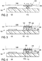
- Fig. 2 shows a schematic representation of an optical vital signs sensor according to an aspect of the invention.
- the PPG sensor 100 comprises a contact surface 101 which is placed in direct contact to a skin 1000 of a user.
- the converting plate can be directly mounted onto the light source area.
- the PPG sensor 100 also comprises at least one light source 110 as well as at least one photo detector unit 120.
- the at least one light source 110 emits light into the direction of the contact surface 101.
- a color converting plate unit 200 is provided between the at least one light source 110 and the contact surface 101.
- the color converting plate unit 200 can for example be implemented as a ceramic phosphor color converting plate.
- the at least one light source 110 can be implemented as a InGaN light emitting diode which is down-converted to for example yellow (having a wavelength of 570 nm) for example by means of the color conversion plate unit 200.
- the color converting plate unit 200 is arranged at the contact surface 101 of the sensor, the color converting plate 200 will also be in direct contact to the skin 1000 of a user when the PPG sensor is placed onto the skin 1000 of the user.
- the light from the at least one light source 110 which is emitting from the contact surface 101 of the PPG sensor should preferably have a wavelength in the green/yellow range (e.g.in the area of 500 to 600 nm).
- a wavelength in the green/yellow range e.g.in the area of 500 to 600 nm.
- This can either be achieved by a light source or a light emitting diode which is directly outputting light at this wavelength or this can be achieved by using a color converting plate unit 200 to change the color of the light from the light source to a desired color temperature.
- the wavelength of the light from the light source 110 is changed by the color converting plate 200.
- Fig. 3 shows a schematic representation of an optical vital signs sensor according to a further aspect of the invention.
- the PPG sensor according to Fig. 3 substantially corresponds to the PPG sensor according to Fig. 2 with a coating 210 on top of the color converting plate 200 and optionally with a diffusing chamber 220.
- the coating or layer 210 on top of the color converting plate 200 can be implemented as an angle selective film which transmits light at small angles of incidence while reflecting light at large angles of incidence.
- the angle selective film 210 may comprise a multi-layer thin film interference filter like a dielectric mirror.
- the optional diffusing chamber 220 can optionally be arranged around the light source or light emitting diode 110 and is used to recycle light as shown in Fig. 3 .
- the light source 110 emits light and a part of this light 103 passes through the color converting plate 200 and the angle selective film 210. Other parts of this light with different angles of incidence 104 are reflected from the angle selective film or coating 110. In addition, further light 105 can be recycled by the diffusion chamber 220 and can be redirected towards the color converting plate unit 200 with a different angle.
- Fig. 4 shows a schematic representation of an optical vital signs sensor according to a further aspect of the invention.
- the PPG sensor according to Fig. 4 substantially corresponds to the PPG sensor according to Fig. 4 with a diffusion chamber 220 around the light source 110 as well as a long wave pass filter LWPF 230 on top of the color converting plate 200.
- the long-wave pass filter 230 can comprise a dielectric multi-layer stack which allows long wave like green/yellow light to be transmitted while reflecting short waves like blue light.
- the long-wave pass filter coating 230 on top of the color converting plate 200 is part of the contact surface 101 of the PPG sensor such that the coating 230 is in direct contact with the skin of a user.
- a part 103 of the light from the light source 110 passes through the color converting plate 200 and the long-wave pass filter 230 and enters the skin 1000 of a user.
- a further part 104a is reflected by the low-wave pass filter 230 and can be recycled 105a by the diffusion chamber 220.
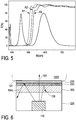
- Fig. 5 shows a graph indicating the function of the transmittance over the wavelength of the optical vital signs sensor according to Fig. 4 .
- a long-wave pass filter with a blue spectrum as well as a down-converted yellow spectrum A1, A2, A3 is depicted.
- Fig. 6 shows a basic representation of part of an optical vital signs sensor according to a further aspect of the invention.
- the aspect of the invention according to Fig. 6 is a combination of the PPG sensor of Fig. 3 and 4 .
- a light source 110 is optionally surrounded by a diffusing chamber 220 and a color converting plate 200.
- a long wave pass filter coating 230 is provided on top of the color converting plate 200.
- an angle selective filter coating 210 is provided on top of this long wave pass filter coating 230.
- the PPG sensor according to this aspect of the invention only green/yellow light 103 at small angles is transmitted through the two coatings 210, 230 while unconverted light (i.e. short wavelength pump- light104c) is reflected by the long-wave pass filter coating 230.
- converted light 106 which still has large angles of incidence is reflected by the angle selective filter coating 210.
- the diffusion chamber 220 can be used to recycle light.
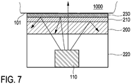
- Fig. 7 shows a basic representation of a part of an optical vital signs sensor according to a further aspect of the invention.
- the PPG sensor according to this aspect sub stantially corresponds to the PPG sensor according to Fig. 6 , wherein the order of the angle selective for a film coating 210 and the long wave pass filter coating 230 is changed.
- the PPG sensor according to Fig. 6 appears to be more effective than the PPG sensor according to Fig. 7 .
- the long wave pass filter coating 230 is able to reflect unconverted light at large angles of incidences.
- optical coupling material such as a gel, liquid or oil can be provided at the contact surface 101 of the PPG sensor.
- Fig. 8 shows a graph for illustrating a relative DC power and AC/DC signal of an optical vital signs sensor according to an aspect of the invention.
- Fig. 8 one important property of the output signal, namely the modulation signal is depicted.
- the modulation signal relates to the ratio of the AC component to the DC component.
- the modulation AC/DC signal is important, because it is related to intrinsic properties of the skin. It covers the peek-to-peek value of the change in blood volume fraction in one heart pulse (AC signal), but also the skin-dependent reflectance (DCcomponent DC) which is important to know because a low reflectance can be compensated with LED power boost, preserving the same modulation signal.
- Fig. 8 the output signal of the PPG sensor is depicted. Furthermore, the influence of different parts of the body, namely pulsating arterial blood PA, non-pulsating arterial blood NA, venous blood VB and other tissue is depicted. Moreover, incident light I 0 as well as transmitted light TL and absorbed light AL is depicted.
- the AC signal AC represents the component that contains the information which the sensor requires in order to determine a heart rate of a user.
- the AC signal represents the information regarding the pulsating arterial blood, i.e.the change in the blood volume while the DC component of the output signal represents the unwanted background signal, namely the influence of the other tissue, the venous blood VB and the non-pulsating arterial blood NA.
- the DC component can have 0 Hz or may also have a low frequency component which can be caused by leakage light shunted from the light source to the light detector without passing through the skin or tissue of the user (static), a dynamic variation of leakage light caused by motion (dynamic) and light detected by the detector which is reflected by the tissue or skin of the user or other matter like the venous blood VB, fat, bone, water, cell membranes, etc.
- the AC component of the output signal is smaller than the DC component.
- the DC component should be minimized while the AC component should be maximized in order to achieve a maximum modulation signal.
- Fig. 8 two measurements, namely M1 and M2 are depicted, wherein the first measurement M1 is measured at the minimum value of the output signal while the second value is measured at the maximum output signal.
- the modulation signal i.e. the AC/DC signal is sensitive towards the beam pattern and the angle of incidence.
- an angle of incidence of greater than 45° should be avoided while small beam angles around 0° and a beam angle pointing in the opposite direction as towards the photodiode can also be used.
- an improved PPG signal can be obtained if the beam angle of the light source is ⁇ ⁇ 20°.
- Fig. 9 shows a basic representation of a vital signs sensor.
- the vital signs sensor according to Fig. 9 comprises at least one light source 110, at least one photodiode 120 as well as at least one light guide 400.
- the light guide 400 is arranged between the at least one light source 110 and the at least one photodiode 120.
- the light guide 400 is implemented as a light transport unit 450 which is able to transport light from the at least one light source (for example a LED which is implemented as a side emitter) towards the at least one photodiode 120.
- the distal end of the light transport unit 450 has an inclination 451 such that the light 111 from the at least one light source 110 is redirected towards the skin of the user 1000.
- the distance between the photodiode 120 and the output end of the light guide unit 450 can be significantly reduced and a flat design with a low building height is possible. Furthermore, a color converting plate 200 as described above can be provided between the light guide 400 and the skin 1000 of a user.
- Fig. 10 shows a basic representation of a vital signs sensor.
- the vital signs sensor can comprise at least one light unit 110, a photo detector 120 and an optical angle selective foil 200.
- the angle selective optical foil as color converting plate unit 200 is able to allow light to transmit within a selected angle range.
- the color converting unit can also be implemented with an optical holographic light shaping diffuser or direction turning film DTF.
- the color converting unit 200 is used to shape, direct, redirect, control or manage the light beam from the light source such that the angular range of the beam is limited or restricted.
- a single unit or device may fulfill the functions of several items The mere fact that certain measures are recited in mutual different dependent claims does not indicate that a combination of these measurements cannot be used to advantage.
- a computer program may be stored/distributed on a suitable medium such as an optical storage medium or a solid state medium, supplied together with or as a part of other hardware, but may also be distributed in other forms such as via the internet or other wired or wireless telecommunication systems.
Landscapes
- Health & Medical Sciences (AREA)
- Life Sciences & Earth Sciences (AREA)
- Physics & Mathematics (AREA)
- Cardiology (AREA)
- Medical Informatics (AREA)
- Animal Behavior & Ethology (AREA)
- Pathology (AREA)
- Engineering & Computer Science (AREA)
- Biomedical Technology (AREA)
- Heart & Thoracic Surgery (AREA)
- Veterinary Medicine (AREA)
- Molecular Biology (AREA)
- Surgery (AREA)
- Biophysics (AREA)
- General Health & Medical Sciences (AREA)
- Public Health (AREA)
- Physiology (AREA)
- Spectroscopy & Molecular Physics (AREA)
- Optics & Photonics (AREA)
- Hematology (AREA)
- Measuring Pulse, Heart Rate, Blood Pressure Or Blood Flow (AREA)
- Measurement Of The Respiration, Hearing Ability, Form, And Blood Characteristics Of Living Organisms (AREA)
- Measuring And Recording Apparatus For Diagnosis (AREA)
Applications Claiming Priority (2)
| Application Number | Priority Date | Filing Date | Title |
|---|---|---|---|
| EP15160262 | 2015-03-23 | ||
| PCT/EP2016/055482 WO2016150749A1 (en) | 2015-03-23 | 2016-03-15 | Optical vital signs sensor |
Publications (2)
| Publication Number | Publication Date |
|---|---|
| EP3273850A1 EP3273850A1 (en) | 2018-01-31 |
| EP3273850B1 true EP3273850B1 (en) | 2021-11-24 |
Family
ID=52780411
Family Applications (1)
| Application Number | Title | Priority Date | Filing Date |
|---|---|---|---|
| EP16714251.2A Active EP3273850B1 (en) | 2015-03-23 | 2016-03-15 | Optical vital signs sensor |
Country Status (6)
| Country | Link |
|---|---|
| US (2) | US20180049656A1 (enExample) |
| EP (1) | EP3273850B1 (enExample) |
| JP (1) | JP6885868B2 (enExample) |
| CN (1) | CN107371361B (enExample) |
| RU (1) | RU2720663C2 (enExample) |
| WO (1) | WO2016150749A1 (enExample) |
Families Citing this family (29)
| Publication number | Priority date | Publication date | Assignee | Title |
|---|---|---|---|---|
| US10117586B1 (en) | 2014-03-31 | 2018-11-06 | Sensogram Technologies, Inc. | Continuous non-invasive wearable blood pressure monitoring system |
| US10327649B1 (en) | 2014-03-31 | 2019-06-25 | Sensogram Technologies, Inc. | Non-invasive wearable blood pressure monitoring system |
| AU2016315947B2 (en) | 2015-08-31 | 2021-02-18 | Masimo Corporation | Wireless patient monitoring systems and methods |
| US10117598B1 (en) | 2015-11-08 | 2018-11-06 | Sensogram Technologies, Inc. | Non-invasive wearable respiration rate monitoring system |
| WO2018152186A1 (en) * | 2017-02-17 | 2018-08-23 | Sensogram Technologies, Inc | Integrated biosensor |
| WO2019215723A1 (en) | 2018-05-10 | 2019-11-14 | CardiacSense Ltd. | A displacement sensor for use in measuring biological parameters |
| EP3626159A1 (en) * | 2018-09-24 | 2020-03-25 | Koninklijke Philips N.V. | Body mountable sensor unit |
| WO2020194036A1 (en) * | 2019-03-28 | 2020-10-01 | Aktiia Ltd | Ppg sensor having a high signal to noise ratio |
| US11678829B2 (en) | 2019-04-17 | 2023-06-20 | Masimo Corporation | Physiological monitoring device attachment assembly |
| EP3738502A1 (en) * | 2019-05-14 | 2020-11-18 | Koninklijke Philips N.V. | An assembly for mounting a sensor on skin |
| USD985498S1 (en) | 2019-08-16 | 2023-05-09 | Masimo Corporation | Connector |
| USD919094S1 (en) | 2019-08-16 | 2021-05-11 | Masimo Corporation | Blood pressure device |
| USD919100S1 (en) | 2019-08-16 | 2021-05-11 | Masimo Corporation | Holder for a patient monitor |
| USD921202S1 (en) | 2019-08-16 | 2021-06-01 | Masimo Corporation | Holder for a blood pressure device |
| USD917704S1 (en) | 2019-08-16 | 2021-04-27 | Masimo Corporation | Patient monitor |
| CN112401900B (zh) * | 2019-08-19 | 2023-08-11 | Oppo广东移动通信有限公司 | 信号处理方法、装置、电子设备和计算机可读存储介质 |
| USD927699S1 (en) | 2019-10-18 | 2021-08-10 | Masimo Corporation | Electrode pad |
| KR20220129033A (ko) | 2020-01-13 | 2022-09-22 | 마시모 코오퍼레이션 | 생리학적 파라미터 모니터링 기능이 있는 웨어러블 디바이스 |
| USD933232S1 (en) | 2020-05-11 | 2021-10-12 | Masimo Corporation | Blood pressure monitor |
| USD979516S1 (en) | 2020-05-11 | 2023-02-28 | Masimo Corporation | Connector |
| CN114245721A (zh) * | 2020-05-22 | 2022-03-25 | 谷歌有限责任公司 | 在检测光电容积描记时用于光学放大的掺铒玻璃 |
| KR102876929B1 (ko) * | 2020-06-05 | 2025-10-24 | 삼성전자주식회사 | 생체 센서, 생체 센서 어레이 및 장치 |
| RU2770266C2 (ru) * | 2020-07-16 | 2022-04-15 | Общество с ограниченной ответственностью "Оптические медицинские диагностические системы" (ООО "ОДС-МЕД") | Датчик для оптического церебрального оксиметра, устройство фиксации датчика к голове пациента и способ работы датчика |
| CN112040052B (zh) * | 2020-08-12 | 2022-05-17 | 维沃移动通信有限公司 | 一种检测模组及电子设备 |
| CN111887827A (zh) * | 2020-08-25 | 2020-11-06 | 复旦大学附属中山医院 | 基于拜尔滤镜的多光谱ppg设备及其应用 |
| WO2022221998A1 (zh) * | 2021-04-19 | 2022-10-27 | 深圳市汇顶科技股份有限公司 | 生物特征检测装置和可穿戴设备 |
| EP4370022A1 (en) | 2021-07-13 | 2024-05-22 | Masimo Corporation | Wearable device with physiological parameters monitoring |
| WO2024071696A1 (ko) * | 2022-09-26 | 2024-04-04 | 삼성전자주식회사 | 광학 코팅층을 포함하는 링 형상의 전자 장치 |
| US20240138728A1 (en) * | 2022-11-02 | 2024-05-02 | Biointellisense, Inc. | Wearable vital signs monitor with skin tone detection |
Family Cites Families (37)
| Publication number | Priority date | Publication date | Assignee | Title |
|---|---|---|---|---|
| EP0527703B1 (de) * | 1991-08-12 | 1995-06-28 | AVL Medical Instruments AG | Einrichtung zur Messung mindestens einer Gassättigung, insbesondere der Sauerstoffsättigung von Blut |
| US5528720A (en) * | 1992-03-23 | 1996-06-18 | Minnesota Mining And Manufacturing Co. | Tapered multilayer luminaire devices |
| KR100495338B1 (ko) * | 1997-01-27 | 2005-06-14 | 피터 디. 하랜드 | 광학 기판으로부터의 반사를 감소시키기 위한 코팅막, 반사 감소 방법 및 장치 |
| JP2001025462A (ja) * | 1999-05-10 | 2001-01-30 | Denso Corp | 生体信号検出装置 |
| US6694158B2 (en) * | 2001-04-11 | 2004-02-17 | Motorola, Inc. | System using a portable detection device for detection of an analyte through body tissue |
| US20040159900A1 (en) * | 2003-01-27 | 2004-08-19 | 3M Innovative Properties Company | Phosphor based light sources having front illumination |
| CN1532449A (zh) * | 2003-03-25 | 2004-09-29 | 三丰医疗器材股份有限公司 | 医疗用灯具及其制法 |
| US20050218810A1 (en) * | 2004-04-02 | 2005-10-06 | Shenzhen Dicheng Technology Company Limited | Efficient flat light source |
| CA2574675C (en) * | 2004-07-20 | 2015-11-24 | Resonant Medical Inc. | Calibrating imaging devices |
| WO2006110488A2 (en) | 2005-04-08 | 2006-10-19 | Ric Investments, Llc | High efficiency photoplethysmographic sensor with coupling gel |
| AU2007249858B2 (en) * | 2006-05-12 | 2013-01-31 | Northshore University Healthsystem | Systems, methods, and apparatuses of low-coherence enhanced backscattering spectroscopy |
| KR100827138B1 (ko) * | 2006-08-10 | 2008-05-02 | 삼성전자주식회사 | 생체 정보 측정 장치 |
| US20080049445A1 (en) * | 2006-08-25 | 2008-02-28 | Philips Lumileds Lighting Company, Llc | Backlight Using High-Powered Corner LED |
| US8781544B2 (en) | 2007-03-27 | 2014-07-15 | Cercacor Laboratories, Inc. | Multiple wavelength optical sensor |
| CN101800219B (zh) * | 2009-02-09 | 2019-09-17 | 晶元光电股份有限公司 | 发光元件 |
| WO2011030436A1 (ja) * | 2009-09-11 | 2011-03-17 | コニカミノルタオプト株式会社 | 画像投影装置 |
| KR101077990B1 (ko) * | 2010-02-12 | 2011-10-31 | 삼성엘이디 주식회사 | 형광체, 발광장치, 면광원장치, 디스플레이 장치 및 조명장치 |
| JP2011181579A (ja) * | 2010-02-26 | 2011-09-15 | Panasonic Corp | 発光装置、及びこれを用いた照明光源、表示装置ならびに電子機器 |
| US9265457B2 (en) * | 2010-06-03 | 2016-02-23 | Koninklijke Philips N.V. | Apparatus and method for measuring a tissue analyte such as bilirubin using the Brewster's angle |
| US9151468B2 (en) * | 2010-06-28 | 2015-10-06 | Axlen, Inc. | High brightness illumination devices using wavelength conversion materials |
| RU2454924C2 (ru) * | 2010-07-20 | 2012-07-10 | Андрей Викторович Демидюк | Система контроля жизненно важных показателей здоровья пациента |
| WO2012050847A2 (en) * | 2010-09-28 | 2012-04-19 | Masimo Corporation | Depth of consciousness monitor including oximeter |
| JP5682200B2 (ja) * | 2010-09-28 | 2015-03-11 | セイコーエプソン株式会社 | 生体情報検出器及び生体情報測定装置 |
| CN103476330B (zh) * | 2011-04-21 | 2016-07-13 | 皇家飞利浦有限公司 | 用于人的生命体征测量的设备和方法 |
| US20140107435A1 (en) * | 2011-05-16 | 2014-04-17 | Cardiogal Ltd. | Methods and systems of aiming sensor(s) for measuring cardiac parameters |
| GB2494622A (en) * | 2011-08-30 | 2013-03-20 | Oxitone Medical Ltd | Wearable pulse oximetry device |
| JP6002374B2 (ja) * | 2011-09-20 | 2016-10-05 | ローム株式会社 | 脈波センサ |
| RU2631554C2 (ru) * | 2012-03-09 | 2017-09-25 | Филипс Лайтинг Холдинг Б.В. | Светоизлучающее устройство с регулируемым цветом |
| US9883824B2 (en) * | 2012-08-20 | 2018-02-06 | Taiwan Biophotonic Corporation | Detecting device |
| US10226297B2 (en) * | 2012-09-06 | 2019-03-12 | Covidien Lp | Medical devices and methods incorporating frustrated total internal reflection for energy-efficient sealing and cutting of tissue using light energy |
| DE102012111123A1 (de) * | 2012-09-26 | 2014-03-27 | Osram Opto Semiconductors Gmbh | Licht emittierendes Halbleiterbauelement |
| DE102012217643A1 (de) * | 2012-09-27 | 2014-03-27 | Osram Opto Semiconductors Gmbh | Optoelektronisches Bauelement |
| EP2769667A1 (en) * | 2013-02-22 | 2014-08-27 | Koninklijke Philips N.V. | Marker with light emitting area for use in determining vital sign information |
| JP2014171511A (ja) * | 2013-03-06 | 2014-09-22 | Olympus Corp | 被検体観察システム及びその方法 |
| WO2015030832A1 (en) * | 2013-08-31 | 2015-03-05 | Pandata Research Llc | Integrated optoelectronic module for physiological measurements and methods of use of the module |
| US10060788B2 (en) * | 2014-04-07 | 2018-08-28 | Physical Enterprises Inc. | Systems and methods for monitoring physiological parameters |
| RU2703638C9 (ru) * | 2014-10-02 | 2019-11-25 | Конинклейке Филипс Н.В. | Оптический датчик жизненных показателей |
-
2016
- 2016-03-15 EP EP16714251.2A patent/EP3273850B1/en active Active
- 2016-03-15 WO PCT/EP2016/055482 patent/WO2016150749A1/en not_active Ceased
- 2016-03-15 CN CN201680017586.XA patent/CN107371361B/zh active Active
- 2016-03-15 RU RU2017137138A patent/RU2720663C2/ru active
- 2016-03-15 US US15/560,243 patent/US20180049656A1/en not_active Abandoned
- 2016-03-15 JP JP2017543736A patent/JP6885868B2/ja active Active
-
2022
- 2022-04-05 US US17/713,274 patent/US20220225886A1/en not_active Abandoned
Also Published As
| Publication number | Publication date |
|---|---|
| CN107371361A (zh) | 2017-11-21 |
| JP2018512187A (ja) | 2018-05-17 |
| RU2017137138A3 (enExample) | 2019-07-17 |
| JP6885868B2 (ja) | 2021-06-16 |
| WO2016150749A1 (en) | 2016-09-29 |
| US20220225886A1 (en) | 2022-07-21 |
| CN107371361B (zh) | 2023-07-25 |
| EP3273850A1 (en) | 2018-01-31 |
| RU2017137138A (ru) | 2019-04-23 |
| RU2720663C2 (ru) | 2020-05-12 |
| US20180049656A1 (en) | 2018-02-22 |
Similar Documents
| Publication | Publication Date | Title |
|---|---|---|
| US20220225886A1 (en) | Optical vital signs sensor | |
| US10799128B2 (en) | Optical vital signs sensor | |
| EP3380002B1 (en) | Wearable device and system for acquiring physiological information of a subject | |
| US9241644B2 (en) | Biological information detector, biological information measuring device, and method for designing reflecting part in biological information detector | |
| US10376164B2 (en) | Vital signs sensor and method of measuring vital signs of a user | |
| US20170215747A1 (en) | Optical vital signs sensor | |
| JP2010521266A (ja) | 血液成分濃度の非侵襲連続測定法 | |
| JP2016511659A (ja) | 対象者のバイタルサイン情報を決定するためのシステム及び方法 | |
| EP2665418A2 (en) | Systems, devices and methods for monitoring hemodynamics | |
| JP2019513035A (ja) | 心臓血管診断のための光学測定デバイス | |
| US12109011B2 (en) | Biological signal measuring device | |
| WO2017133883A1 (en) | Optical vital signs sensor | |
| JP2008099890A (ja) | 生体情報測定装置 | |
| WO2016055260A1 (en) | Optical vital signs sensor. | |
| EP3534775B1 (en) | Device for physiological parameter detection | |
| McEwen et al. | Noninvasive monitoring with strongly absorbed light | |
| NL2034027B1 (en) | Multi-frequency speckle sensing | |
| WO2025156356A1 (zh) | 一种无创光电反射式生理参数测量的传感器及可穿戴装置 | |
| WO2014052040A2 (en) | Noninvasive absolute oximetry of brain tissue |
Legal Events
| Date | Code | Title | Description |
|---|---|---|---|
| STAA | Information on the status of an ep patent application or granted ep patent |
Free format text: STATUS: THE INTERNATIONAL PUBLICATION HAS BEEN MADE |
|
| PUAI | Public reference made under article 153(3) epc to a published international application that has entered the european phase |
Free format text: ORIGINAL CODE: 0009012 |
|
| STAA | Information on the status of an ep patent application or granted ep patent |
Free format text: STATUS: REQUEST FOR EXAMINATION WAS MADE |
|
| 17P | Request for examination filed |
Effective date: 20171023 |
|
| AK | Designated contracting states |
Kind code of ref document: A1 Designated state(s): AL AT BE BG CH CY CZ DE DK EE ES FI FR GB GR HR HU IE IS IT LI LT LU LV MC MK MT NL NO PL PT RO RS SE SI SK SM TR |
|
| AX | Request for extension of the european patent |
Extension state: BA ME |
|
| DAV | Request for validation of the european patent (deleted) | ||
| DAX | Request for extension of the european patent (deleted) | ||
| RAP1 | Party data changed (applicant data changed or rights of an application transferred) |
Owner name: KONINKLIJKE PHILIPS N.V. |
|
| GRAP | Despatch of communication of intention to grant a patent |
Free format text: ORIGINAL CODE: EPIDOSNIGR1 |
|
| STAA | Information on the status of an ep patent application or granted ep patent |
Free format text: STATUS: GRANT OF PATENT IS INTENDED |
|
| RIC1 | Information provided on ipc code assigned before grant |
Ipc: A61B 5/024 20060101AFI20210527BHEP Ipc: A61B 5/1455 20060101ALI20210527BHEP Ipc: H01L 33/44 20100101ALI20210527BHEP Ipc: H01L 33/50 20100101ALI20210527BHEP |
|
| INTG | Intention to grant announced |
Effective date: 20210616 |
|
| GRAS | Grant fee paid |
Free format text: ORIGINAL CODE: EPIDOSNIGR3 |
|
| GRAA | (expected) grant |
Free format text: ORIGINAL CODE: 0009210 |
|
| STAA | Information on the status of an ep patent application or granted ep patent |
Free format text: STATUS: THE PATENT HAS BEEN GRANTED |
|
| AK | Designated contracting states |
Kind code of ref document: B1 Designated state(s): AL AT BE BG CH CY CZ DE DK EE ES FI FR GB GR HR HU IE IS IT LI LT LU LV MC MK MT NL NO PL PT RO RS SE SI SK SM TR |
|
| REG | Reference to a national code |
Ref country code: GB Ref legal event code: FG4D |
|
| REG | Reference to a national code |
Ref country code: AT Ref legal event code: REF Ref document number: 1449225 Country of ref document: AT Kind code of ref document: T Effective date: 20211215 |
|
| REG | Reference to a national code |
Ref country code: DE Ref legal event code: R096 Ref document number: 602016066538 Country of ref document: DE |
|
| REG | Reference to a national code |
Ref country code: IE Ref legal event code: FG4D |
|
| REG | Reference to a national code |
Ref country code: LT Ref legal event code: MG9D |
|
| REG | Reference to a national code |
Ref country code: NL Ref legal event code: MP Effective date: 20211124 |
|
| REG | Reference to a national code |
Ref country code: AT Ref legal event code: MK05 Ref document number: 1449225 Country of ref document: AT Kind code of ref document: T Effective date: 20211124 |
|
| PG25 | Lapsed in a contracting state [announced via postgrant information from national office to epo] |
Ref country code: RS Free format text: LAPSE BECAUSE OF FAILURE TO SUBMIT A TRANSLATION OF THE DESCRIPTION OR TO PAY THE FEE WITHIN THE PRESCRIBED TIME-LIMIT Effective date: 20211124 Ref country code: LT Free format text: LAPSE BECAUSE OF FAILURE TO SUBMIT A TRANSLATION OF THE DESCRIPTION OR TO PAY THE FEE WITHIN THE PRESCRIBED TIME-LIMIT Effective date: 20211124 Ref country code: FI Free format text: LAPSE BECAUSE OF FAILURE TO SUBMIT A TRANSLATION OF THE DESCRIPTION OR TO PAY THE FEE WITHIN THE PRESCRIBED TIME-LIMIT Effective date: 20211124 Ref country code: BG Free format text: LAPSE BECAUSE OF FAILURE TO SUBMIT A TRANSLATION OF THE DESCRIPTION OR TO PAY THE FEE WITHIN THE PRESCRIBED TIME-LIMIT Effective date: 20220224 Ref country code: AT Free format text: LAPSE BECAUSE OF FAILURE TO SUBMIT A TRANSLATION OF THE DESCRIPTION OR TO PAY THE FEE WITHIN THE PRESCRIBED TIME-LIMIT Effective date: 20211124 |
|
| PG25 | Lapsed in a contracting state [announced via postgrant information from national office to epo] |
Ref country code: IS Free format text: LAPSE BECAUSE OF FAILURE TO SUBMIT A TRANSLATION OF THE DESCRIPTION OR TO PAY THE FEE WITHIN THE PRESCRIBED TIME-LIMIT Effective date: 20220324 Ref country code: SE Free format text: LAPSE BECAUSE OF FAILURE TO SUBMIT A TRANSLATION OF THE DESCRIPTION OR TO PAY THE FEE WITHIN THE PRESCRIBED TIME-LIMIT Effective date: 20211124 Ref country code: PT Free format text: LAPSE BECAUSE OF FAILURE TO SUBMIT A TRANSLATION OF THE DESCRIPTION OR TO PAY THE FEE WITHIN THE PRESCRIBED TIME-LIMIT Effective date: 20220324 Ref country code: PL Free format text: LAPSE BECAUSE OF FAILURE TO SUBMIT A TRANSLATION OF THE DESCRIPTION OR TO PAY THE FEE WITHIN THE PRESCRIBED TIME-LIMIT Effective date: 20211124 Ref country code: NO Free format text: LAPSE BECAUSE OF FAILURE TO SUBMIT A TRANSLATION OF THE DESCRIPTION OR TO PAY THE FEE WITHIN THE PRESCRIBED TIME-LIMIT Effective date: 20220224 Ref country code: NL Free format text: LAPSE BECAUSE OF FAILURE TO SUBMIT A TRANSLATION OF THE DESCRIPTION OR TO PAY THE FEE WITHIN THE PRESCRIBED TIME-LIMIT Effective date: 20211124 Ref country code: LV Free format text: LAPSE BECAUSE OF FAILURE TO SUBMIT A TRANSLATION OF THE DESCRIPTION OR TO PAY THE FEE WITHIN THE PRESCRIBED TIME-LIMIT Effective date: 20211124 Ref country code: HR Free format text: LAPSE BECAUSE OF FAILURE TO SUBMIT A TRANSLATION OF THE DESCRIPTION OR TO PAY THE FEE WITHIN THE PRESCRIBED TIME-LIMIT Effective date: 20211124 Ref country code: GR Free format text: LAPSE BECAUSE OF FAILURE TO SUBMIT A TRANSLATION OF THE DESCRIPTION OR TO PAY THE FEE WITHIN THE PRESCRIBED TIME-LIMIT Effective date: 20220225 Ref country code: ES Free format text: LAPSE BECAUSE OF FAILURE TO SUBMIT A TRANSLATION OF THE DESCRIPTION OR TO PAY THE FEE WITHIN THE PRESCRIBED TIME-LIMIT Effective date: 20211124 |
|
| PG25 | Lapsed in a contracting state [announced via postgrant information from national office to epo] |
Ref country code: SM Free format text: LAPSE BECAUSE OF FAILURE TO SUBMIT A TRANSLATION OF THE DESCRIPTION OR TO PAY THE FEE WITHIN THE PRESCRIBED TIME-LIMIT Effective date: 20211124 Ref country code: SK Free format text: LAPSE BECAUSE OF FAILURE TO SUBMIT A TRANSLATION OF THE DESCRIPTION OR TO PAY THE FEE WITHIN THE PRESCRIBED TIME-LIMIT Effective date: 20211124 Ref country code: RO Free format text: LAPSE BECAUSE OF FAILURE TO SUBMIT A TRANSLATION OF THE DESCRIPTION OR TO PAY THE FEE WITHIN THE PRESCRIBED TIME-LIMIT Effective date: 20211124 Ref country code: EE Free format text: LAPSE BECAUSE OF FAILURE TO SUBMIT A TRANSLATION OF THE DESCRIPTION OR TO PAY THE FEE WITHIN THE PRESCRIBED TIME-LIMIT Effective date: 20211124 Ref country code: DK Free format text: LAPSE BECAUSE OF FAILURE TO SUBMIT A TRANSLATION OF THE DESCRIPTION OR TO PAY THE FEE WITHIN THE PRESCRIBED TIME-LIMIT Effective date: 20211124 Ref country code: CZ Free format text: LAPSE BECAUSE OF FAILURE TO SUBMIT A TRANSLATION OF THE DESCRIPTION OR TO PAY THE FEE WITHIN THE PRESCRIBED TIME-LIMIT Effective date: 20211124 |
|
| REG | Reference to a national code |
Ref country code: DE Ref legal event code: R097 Ref document number: 602016066538 Country of ref document: DE |
|
| PLBE | No opposition filed within time limit |
Free format text: ORIGINAL CODE: 0009261 |
|
| STAA | Information on the status of an ep patent application or granted ep patent |
Free format text: STATUS: NO OPPOSITION FILED WITHIN TIME LIMIT |
|
| PG25 | Lapsed in a contracting state [announced via postgrant information from national office to epo] |
Ref country code: MC Free format text: LAPSE BECAUSE OF FAILURE TO SUBMIT A TRANSLATION OF THE DESCRIPTION OR TO PAY THE FEE WITHIN THE PRESCRIBED TIME-LIMIT Effective date: 20211124 Ref country code: AL Free format text: LAPSE BECAUSE OF FAILURE TO SUBMIT A TRANSLATION OF THE DESCRIPTION OR TO PAY THE FEE WITHIN THE PRESCRIBED TIME-LIMIT Effective date: 20211124 |
|
| REG | Reference to a national code |
Ref country code: CH Ref legal event code: PL |
|
| 26N | No opposition filed |
Effective date: 20220825 |
|
| PG25 | Lapsed in a contracting state [announced via postgrant information from national office to epo] |
Ref country code: SI Free format text: LAPSE BECAUSE OF FAILURE TO SUBMIT A TRANSLATION OF THE DESCRIPTION OR TO PAY THE FEE WITHIN THE PRESCRIBED TIME-LIMIT Effective date: 20211124 |
|
| REG | Reference to a national code |
Ref country code: BE Ref legal event code: MM Effective date: 20220331 |
|
| PG25 | Lapsed in a contracting state [announced via postgrant information from national office to epo] |
Ref country code: LU Free format text: LAPSE BECAUSE OF NON-PAYMENT OF DUE FEES Effective date: 20220315 Ref country code: LI Free format text: LAPSE BECAUSE OF NON-PAYMENT OF DUE FEES Effective date: 20220331 Ref country code: IE Free format text: LAPSE BECAUSE OF NON-PAYMENT OF DUE FEES Effective date: 20220315 Ref country code: CH Free format text: LAPSE BECAUSE OF NON-PAYMENT OF DUE FEES Effective date: 20220331 |
|
| PG25 | Lapsed in a contracting state [announced via postgrant information from national office to epo] |
Ref country code: BE Free format text: LAPSE BECAUSE OF NON-PAYMENT OF DUE FEES Effective date: 20220331 |
|
| PG25 | Lapsed in a contracting state [announced via postgrant information from national office to epo] |
Ref country code: IT Free format text: LAPSE BECAUSE OF FAILURE TO SUBMIT A TRANSLATION OF THE DESCRIPTION OR TO PAY THE FEE WITHIN THE PRESCRIBED TIME-LIMIT Effective date: 20211124 |
|
| PG25 | Lapsed in a contracting state [announced via postgrant information from national office to epo] |
Ref country code: HU Free format text: LAPSE BECAUSE OF FAILURE TO SUBMIT A TRANSLATION OF THE DESCRIPTION OR TO PAY THE FEE WITHIN THE PRESCRIBED TIME-LIMIT; INVALID AB INITIO Effective date: 20160315 |
|
| PG25 | Lapsed in a contracting state [announced via postgrant information from national office to epo] |
Ref country code: MK Free format text: LAPSE BECAUSE OF FAILURE TO SUBMIT A TRANSLATION OF THE DESCRIPTION OR TO PAY THE FEE WITHIN THE PRESCRIBED TIME-LIMIT Effective date: 20211124 Ref country code: CY Free format text: LAPSE BECAUSE OF FAILURE TO SUBMIT A TRANSLATION OF THE DESCRIPTION OR TO PAY THE FEE WITHIN THE PRESCRIBED TIME-LIMIT Effective date: 20211124 |
|
| PG25 | Lapsed in a contracting state [announced via postgrant information from national office to epo] |
Ref country code: MT Free format text: LAPSE BECAUSE OF FAILURE TO SUBMIT A TRANSLATION OF THE DESCRIPTION OR TO PAY THE FEE WITHIN THE PRESCRIBED TIME-LIMIT Effective date: 20211124 |
|
| PGFP | Annual fee paid to national office [announced via postgrant information from national office to epo] |
Ref country code: DE Payment date: 20250327 Year of fee payment: 10 |
|
| PGFP | Annual fee paid to national office [announced via postgrant information from national office to epo] |
Ref country code: FR Payment date: 20250324 Year of fee payment: 10 |
|
| PGFP | Annual fee paid to national office [announced via postgrant information from national office to epo] |
Ref country code: GB Payment date: 20250325 Year of fee payment: 10 |
|
| PG25 | Lapsed in a contracting state [announced via postgrant information from national office to epo] |
Ref country code: TR Free format text: LAPSE BECAUSE OF FAILURE TO SUBMIT A TRANSLATION OF THE DESCRIPTION OR TO PAY THE FEE WITHIN THE PRESCRIBED TIME-LIMIT Effective date: 20211124 |