EP3273607B1 - Procédé et système de synchronisation et de localisation d'un signal radio - Google Patents
Procédé et système de synchronisation et de localisation d'un signal radio Download PDFInfo
- Publication number
- EP3273607B1 EP3273607B1 EP16180271.5A EP16180271A EP3273607B1 EP 3273607 B1 EP3273607 B1 EP 3273607B1 EP 16180271 A EP16180271 A EP 16180271A EP 3273607 B1 EP3273607 B1 EP 3273607B1
- Authority
- EP
- European Patent Office
- Prior art keywords
- frequency
- projection
- chirps
- radio signal
- time
- Prior art date
- Legal status (The legal status is an assumption and is not a legal conclusion. Google has not performed a legal analysis and makes no representation as to the accuracy of the status listed.)
- Active
Links
- 238000000034 method Methods 0.000 title claims description 36
- 239000013598 vector Substances 0.000 claims description 39
- 230000001360 synchronised effect Effects 0.000 claims description 7
- 230000003111 delayed effect Effects 0.000 claims description 2
- 230000002194 synthesizing effect Effects 0.000 claims 1
- 230000004807 localization Effects 0.000 description 19
- QVFWZNCVPCJQOP-UHFFFAOYSA-N chloralodol Chemical compound CC(O)(C)CC(C)OC(O)C(Cl)(Cl)Cl QVFWZNCVPCJQOP-UHFFFAOYSA-N 0.000 description 17
- 238000012545 processing Methods 0.000 description 8
- 125000004122 cyclic group Chemical group 0.000 description 6
- 238000005070 sampling Methods 0.000 description 5
- 230000001066 destructive effect Effects 0.000 description 4
- 238000001514 detection method Methods 0.000 description 4
- 230000006870 function Effects 0.000 description 4
- 230000008569 process Effects 0.000 description 4
- 238000001228 spectrum Methods 0.000 description 4
- 238000007792 addition Methods 0.000 description 3
- 230000008901 benefit Effects 0.000 description 3
- 230000005540 biological transmission Effects 0.000 description 3
- 238000004891 communication Methods 0.000 description 3
- 230000003595 spectral effect Effects 0.000 description 3
- 108010003272 Hyaluronate lyase Proteins 0.000 description 2
- 238000006243 chemical reaction Methods 0.000 description 2
- 238000012937 correction Methods 0.000 description 2
- 230000004044 response Effects 0.000 description 2
- 230000009471 action Effects 0.000 description 1
- 230000006978 adaptation Effects 0.000 description 1
- 230000032683 aging Effects 0.000 description 1
- 238000004364 calculation method Methods 0.000 description 1
- 230000015556 catabolic process Effects 0.000 description 1
- 230000008859 change Effects 0.000 description 1
- 230000001427 coherent effect Effects 0.000 description 1
- 230000001143 conditioned effect Effects 0.000 description 1
- 238000010276 construction Methods 0.000 description 1
- 239000013078 crystal Substances 0.000 description 1
- 238000006731 degradation reaction Methods 0.000 description 1
- 238000011161 development Methods 0.000 description 1
- 230000018109 developmental process Effects 0.000 description 1
- 239000006185 dispersion Substances 0.000 description 1
- 230000000694 effects Effects 0.000 description 1
- 230000007717 exclusion Effects 0.000 description 1
- 230000001747 exhibiting effect Effects 0.000 description 1
- 238000003306 harvesting Methods 0.000 description 1
- 239000003550 marker Substances 0.000 description 1
- 238000004377 microelectronic Methods 0.000 description 1
- 238000012986 modification Methods 0.000 description 1
- 230000004048 modification Effects 0.000 description 1
- 230000003094 perturbing effect Effects 0.000 description 1
- 230000002441 reversible effect Effects 0.000 description 1
- 230000035945 sensitivity Effects 0.000 description 1
- 230000007480 spreading Effects 0.000 description 1
Images


Classifications
-
- G—PHYSICS
- G01—MEASURING; TESTING
- G01S—RADIO DIRECTION-FINDING; RADIO NAVIGATION; DETERMINING DISTANCE OR VELOCITY BY USE OF RADIO WAVES; LOCATING OR PRESENCE-DETECTING BY USE OF THE REFLECTION OR RERADIATION OF RADIO WAVES; ANALOGOUS ARRANGEMENTS USING OTHER WAVES
- G01S5/00—Position-fixing by co-ordinating two or more direction or position line determinations; Position-fixing by co-ordinating two or more distance determinations
- G01S5/02—Position-fixing by co-ordinating two or more direction or position line determinations; Position-fixing by co-ordinating two or more distance determinations using radio waves
- G01S5/06—Position of source determined by co-ordinating a plurality of position lines defined by path-difference measurements
-
- H—ELECTRICITY
- H04—ELECTRIC COMMUNICATION TECHNIQUE
- H04L—TRANSMISSION OF DIGITAL INFORMATION, e.g. TELEGRAPHIC COMMUNICATION
- H04L27/00—Modulated-carrier systems
- H04L27/10—Frequency-modulated carrier systems, i.e. using frequency-shift keying
- H04L27/103—Chirp modulation
-
- H—ELECTRICITY
- H04—ELECTRIC COMMUNICATION TECHNIQUE
- H04B—TRANSMISSION
- H04B1/00—Details of transmission systems, not covered by a single one of groups H04B3/00 - H04B13/00; Details of transmission systems not characterised by the medium used for transmission
- H04B1/69—Spread spectrum techniques
-
- G—PHYSICS
- G01—MEASURING; TESTING
- G01S—RADIO DIRECTION-FINDING; RADIO NAVIGATION; DETERMINING DISTANCE OR VELOCITY BY USE OF RADIO WAVES; LOCATING OR PRESENCE-DETECTING BY USE OF THE REFLECTION OR RERADIATION OF RADIO WAVES; ANALOGOUS ARRANGEMENTS USING OTHER WAVES
- G01S11/00—Systems for determining distance or velocity not using reflection or reradiation
- G01S11/02—Systems for determining distance or velocity not using reflection or reradiation using radio waves
- G01S11/026—Systems for determining distance or velocity not using reflection or reradiation using radio waves using moving transmitters
-
- G—PHYSICS
- G01—MEASURING; TESTING
- G01S—RADIO DIRECTION-FINDING; RADIO NAVIGATION; DETERMINING DISTANCE OR VELOCITY BY USE OF RADIO WAVES; LOCATING OR PRESENCE-DETECTING BY USE OF THE REFLECTION OR RERADIATION OF RADIO WAVES; ANALOGOUS ARRANGEMENTS USING OTHER WAVES
- G01S5/00—Position-fixing by co-ordinating two or more direction or position line determinations; Position-fixing by co-ordinating two or more distance determinations
- G01S5/02—Position-fixing by co-ordinating two or more direction or position line determinations; Position-fixing by co-ordinating two or more distance determinations using radio waves
- G01S5/0205—Details
- G01S5/0221—Receivers
- G01S5/02213—Receivers arranged in a network for determining the position of a transmitter
- G01S5/02216—Timing or synchronisation of the receivers
-
- H—ELECTRICITY
- H04—ELECTRIC COMMUNICATION TECHNIQUE
- H04L—TRANSMISSION OF DIGITAL INFORMATION, e.g. TELEGRAPHIC COMMUNICATION
- H04L5/00—Arrangements affording multiple use of the transmission path
- H04L5/003—Arrangements for allocating sub-channels of the transmission path
-
- H—ELECTRICITY
- H04—ELECTRIC COMMUNICATION TECHNIQUE
- H04B—TRANSMISSION
- H04B1/00—Details of transmission systems, not covered by a single one of groups H04B3/00 - H04B13/00; Details of transmission systems not characterised by the medium used for transmission
- H04B1/69—Spread spectrum techniques
- H04B2001/6912—Spread spectrum techniques using chirp
Definitions
- the present invention relates, in embodiments, to methods for determining with precision the time of arrival (TOA) of a radio signal to a receiver and, by combining precise determinations of the time of arrival at different sites, the localization of the radio transmitter.
- TOA time of arrival
- loT objects are often simple devices with modest energy resources, as they must rely on local accumulators or energy harvesting. They need therefore wireless connectivity solutions that agree with these conditions.
- Low-throughput long-distance wireless networks are particularly suited to applications in the loT, in particular where low power, long battery autonomy and low cost are sought.
- the LoRa communication system known among others by patent applications EP2767847 and EP2449690 , uses chirp spread-spectrum modulation to achieve these goals.
- Localization is one of the key enablers for the development of the Internet of Things. There is a need for low-power, low-complexity localization methods and devices for mobile nodes.
- Satellite localization systems are known since a considerable time.
- GP, Glonass and Galileo allow precise self-localization of mobile nodes, based on the precise timing of signals received from a constellation of space vehicles whose orbits are precisely known.
- Terrestrial or maritime localization systems based on the timing of radio signals are also known, predating the satellite-systems, and are still used today.
- Radio-based localization often derives the position of an object from the measured times of arrival of a radio signal linking the object to some reference whose position is known.
- the time of arrival of a signal can be determined with methods that exploit the duality between time and frequency in chirp-modulation, as known from EP2767848 and EP2767847
- device-side localization which is the variant used, for example in GPS
- the device In device-side localization, which is the variant used, for example in GPS, the device itself receives the radio signals from a number of beacons and, by timing them, determines the ranges to the beacons and its own location, without further external assistance
- the device whose position is requested sends one or several signals that is received from a plurality of fixed stations, belonging to the network infrastructure.
- the ranges and the location are computed in the network infrastructure.
- Network-side localization transfers most of the computations in the networks structure, which allows a simplification of the end node's hardware.
- Network-side localization permits the localization of transmit-only nodes and is harder to jam than the device-side variant, which is an advantage in security applications.
- Timing a radio signal often involves determining its position on an absolute time axis, determined by an accurate clock, for example a GPS-disciplined clock, or the time difference of arrival between two similar signals. In both cases, the larger the bandwidth of the signal, the easier the localization will be. While a zero-bandwidth CW signal has no time structure and is essentially impossible to time precisely, radar system achieve excellent timing by using very short broad bandwidth radio pulses.
- an accurate clock for example a GPS-disciplined clock
- LoRa is a spread spectrum modulation. Its bandwidth, however, is relatively small: about 125 kHz in most cases, in contrast with radar systems that use some tens of MHz up to several GHz of bandwidth. Therefore, the techniques derived from radar applications are not really effective for LoRa signals. In particular, LoRa signals last much longer, and the structure of the signals does not allow resolving multipath in the time domain.
- Effective localization requires in general a time-of-arrival accuracy of 30 to 300 ns, depending on the propagation conditions and on the precision sought for. With a bandwidth of 125 kHz, the Nyquist sampled data has a resolution of 8 microseconds, about 250 times larger than the target resolution.
- LoRa is chirp-based spread spectrum modulation
- the time of arrival can be estimated from the frequency of the incoming signal which, due to multipath, will be a superposition of several complex exponential signals.
- Algorithms to extract individual components from such a superposition are known, for example the super-resolution MUSIC algorithm. These methods, however, are computationally very intensive, particularly, in our case, where the vectors can be very long, and the number of multipath components is not known in advance.
- the present invention proposes methods of timing a radio signal in a receiver and of positioning a device that are the object of the corresponding independent claims.
- the radio transceiver that is represented schematically in Figure 1 is part of a possible embodiment of the invention. It includes a baseband section 200 and a radiofrequency section 100. Concentrating on the transmitter part, the baseband modulator 150 generates, based on the digital data 152 that are present at its input, a baseband signal whose I and Q component are converted to the desired transmission frequency by the RF section 100 amplified by the power amplifier 120, and transmitted by the antenna.
- This architecture allows several variants and modifications without departing from the frame of the invention, and is a non-limiting example.
- the transceiver could synthesize the polar components amplitude A and phase ⁇ , rather than the Cartesian ones I and Q.
- the conversion of the signal from the baseband to the intended frequency is done, in this example, by mixing in mixer 110 the signal provided by amplifiers 154 with the in-phase and quadrature components of a local carrier generated by circuit 190, and linked to a reference clock 129.
- the receiving part of the transceiver of Figure 1 comprises a low noise amplifier 160 followed to a down-conversion stage 170 that generates a baseband signal comprising a series of chirps, that is then processed by the baseband demodulator 180, whose function is the reverse of that of the modulator 150, and provides a reconstructed digital signal 182.
- the modulator 150 synthesizes a baseband signal that comprises a series of chirps whose frequency changes, along a predetermined time interval, from an initial instantaneous value f 0 to a final instantaneous frequency f 1 . It will be assumed, to simplify the description, that all the chirps have the same duration T, although this is not an absolute requirement for the invention.
- the chirps can be described by the time profile f(t) of their instantaneous frequency or also by the function ⁇ ( t ) defining the phase of the signal as a function of the time. Chirps may have one of a plurality of different profiles, each corresponding to a symbol in a predetermined modulation alphabet.
- the chirps comprised in the signal can be either base chirp (also called unmodulated chirps) that have specific and predefined frequency profile, or one out of a set of possible modulated chirps, obtained by time-shifting cyclically the base chirp's frequency profile.
- Figures 2 - 3 illustrate possible frequency and phase profiles of a base chirp and of a modulated one, while figure 4 shows the real and imaginary components I, Q, of an unmodulated chirp in the time domain.
- the bandwidth BW of the modulated signal is thus determined by the difference between the highest and the lowest frequencies in the chirp and is the same in modulated and unmodulated chirps.
- Figure 2 represents a baseband signal whose bandwidth extends between -BW/2 and BW/ but, of course, the transmitted signal will be converted to a suitable frequency band.
- the information is encoded in the form of chirps that have one out of a plurality of possible cyclic shifts with respect to a predetermined base chirp, each cyclic shift corresponding to a possible modulation symbol.
- LoRa receivers and transmitters are also arranged to synthesize and insert in the signal conjugate chirps, that are complex-conjugate of a base unmodulated chirp.
- LoRa receivers and transmitters are also arranged to synthesize and insert in the signal conjugate chirps, that are complex-conjugate of a base unmodulated chirp.
- the demodulator unit 180 in the receiver can align its time references with that of the transmitter, and determine the amount of cyclical shift imparted to each chirp.
- the operation of evaluating a time shift of a received chirp with respect to a local time reference can be carried out by multiplying the received chirp by a complex conjugate of a locally-generated base chirp, and performing a Fourier transform.
- the position of the maximum of the Fourier transform is indicative of the shift, and of the modulation value.
- Other dechirping methods are possible.
- the operation of multiplying a chirp signal by the conjugate of a base symbol be referred to in the following as "dechirping", and the following Fourier transform as "demodulation"
- cyclic shift value may be used in the following to indicate the modulation in the time domain, and "modulation position", or “peak position” represent the same in the frequency domain.
- N the length of the symbol or, equivalently, the spreading factor, with 1/BW the Nyquist sampling frequency and with N/BW the length of a symbol.
- N is a power of two.
- BW might be 125 KHz N equal to 4096,2048,1024, 512, 256,128,64 or 32.
- the carrier frequency may be in the European 868MHzISM band, or the US 915MHz ISM band.
- a modulated symbol is a cyclic shift of the base symbol, of any number between 0 and N-1.
- a modulation value of 0 is equivalent to the absence of modulation. Since N is a power of two, the value of the cyclic shift can be coded over log 2 N bits.
- the signal transmitted and received by the invention are organized in frames that include a preamble and a data section, suitably encoded.
- the preamble and the data section comprise a series of chirps modulated and/or unmodulated, that allow the receiver to time-align its time reference with that of the transmitter, retrieve information, perform an action, and so on.
- Several structures of frame are possible.
- Figure 5 represents schematically a possible structure of a frame that may include a data packet and/or a ranging request.
- This structure has a preamble that is functional to the demodulation of the message and to the compensation of several drift sources, as it will be explained better later on.
- the header part of the frame is a data field 415 that includes an indication of the frame purpose, and an identification address of the specific recipient device.
- FIG 6 represents a possible architecture of a localization system according to the invention.
- a mobile station 510 is equipped with a LoRa transmitter and broadcasts a message that is received by a plurality of LoRa receivers 523.
- Each of the receivers 523 has access to a synchronised clock 576 that is synchronised with the clocks of all the other receivers 524, such that each receiver can determine the time of arrival of radio signals based on a common time reference.
- Clock synchronization can be obtained by any suitable known means.
- the clocks 576 may be GPS-disciplined units.
- each of the receivers 523 Upon reception of a LoRa signal from the mobile station 510, each of the receivers 523 "timestamps" it with its time of arrival computed on the synchronised clock, and the timestamps are made available to a solver 560 that determines, in known manner, the position of the mobile station 510 based on the times of arrival encoded on the timestamps, and on the known positions of the receivers 523.
- the solver 560 is represented as a remote server but the determination of the location could be carried out in any of the infrastructure nodes 524, in a mobile node, or in any suitable computing unit.
- timing or "timestamping" the signals in the receivers, these terms indicating the act of determining and storing the precise time of arrival of the signal at the receiver, based on a suitable reference clock.
- this may include all or some of the following operations:
- Coarse synchronization is the operation of synchronising the signal received by receivers 521-524 and the signal synthesized by the transmitter 510 at the level of the respective digital samples.
- Coarse synchronization can be carried out by several known methods, including the processing of the detection symbols 411 in the preamble (see Figure 5 ). It is a sequence of base (i.e. un-modulated, or with cyclic shift equal to zero) symbols.
- the detect sequence 411 is used in the receiver to detect the beginning of the signal and, preferably, perform a first synchronization of its time reference with the time reference in the transmitter. By dechirping the detect sequence, the receiver determines a shift amount.
- Frame synchronization is the operation of determining the correspondence between the samples and symbols in the frame. If, as it may be the case, the preamble 411 comprises 16 unmodulated chirps, frame synchronization amount to locating the frame boundaries in the received sampled signal, i.e, which interval of samples belongs to symbol 0, which to symbol 1, and so on.
- the end of the detect sequence is marked by one or more, preferably two, frame synchronization symbols 412 that are chirps modulated with predetermined values, for example a first chirp with a modulation value of 4, and a second one with the opposite modulation N-4.
- the modulation of the frame synchronization symbols is larger, in absolute shift, than three units to minimize the likelihood of errors.
- the use of a single modulated symbol as frame synch marker or of the same modulation value for several symbols are also possible, but not optimal.
- any drift between the frequencies of the time bases in the receiver and in the transmitter will result in an error in the determination of the time of arrival.
- the mobile nodes 510 tend to be low-cost devices and are equipped with inferior clocks, whose frequency can drift due to changes in temperature, aging, driving level, and many other perturbing factors. Slight frequency drifts do not necessarily inhibit demodulation of the LoRa signals. They may increase the error rate, however, and have a very negative influence on ranging and localization.
- the receivers 521-524 are preferably arranged for determining and modelling the frequency drift of the transmitter from the received signal.
- the preamble includes preferably frequency synchronization symbols 413 that consist in one or more, preferably two chirps that are complex conjugate of the base unmodulated chirp.
- the conjugate symbols may be replaced by chirps that have a different bandwidth or duration than the base chirps, thus exhibiting a frequency variation that is faster, or slower than that of the base chirps.
- This variant would require a more complex receiver, but, on the other hand, leaves the conjugate-chirps free to use for data transmission.
- the apparent value of modulation will give the frequency error, due to the time-frequency duality of chirps.
- a silence 420 is inserted after the symbols 413.
- the receiver of the invention proceeds to determine the time of arrival, as it will be detailed.
- the invention exploits the direct relationship between time and frequency that exists in chirp signals and determines the time of arrival from frequency shift.
- the received digital signal is stored in a suitable memory area, and the precise timing is performed on the memorized signal. Since the sampling of the signal is synchronous with the precise clock 576, the precision of the GPS clock is transferred to the samples, and the time of arrival can be determined with the required precision.
- the timing is done on the preamble's detection section 411, as working with unmodulated data is simpler. It must be understood, however, that this feature does not limit the invention.
- the method of timing would be possible in fact on any sequence of symbols whose modulation values are known.
- the storage can be done after frame and frequency synchronization and, preferably the full length of the preamble is stored.
- the goal of the precise timing is determine the time of arrival of the signal with a precision that is adequate for localization purposes, that is with an error of about 4 ns. This may involve several steps.
- a first operation that improves timing is fine timing drift compensation.
- the frequencies of the transmitter's time base and of the receiver's one are not perfectly the same, and the frequency synchronization explained above allows estimating the amount of error. This can be corrected for improved accuracy.
- frequency drift can be compensated by adjusting slopes, initial frequency, and phase of the conjugate chirp that is synthesized locally.
- the chirp slope adjustment is proportional to the estimated frequency error, and can be constant for all symbols or, if needed, adapted for each symbol.
- the chirp initial frequency is offset by an amount that is proportional to the accumulated timing error that is increased progressively at each symbol by a step that is proportionally to the estimated frequency error.
- phase can be adjusted, such that the inter-symbol phase continuity is preserved. Since LoRa preamble signals are relatively long, (up to 250 ms), timing drift compensation allows coherent processing of the whole preamble, or at least of a large part of it, and helps improving the timing precision.
- Timing drift compensation can be obtained also by interpolating the received signal, but this is more expensive computationally.
- a second useful operation is fine time synchronization.
- the initial time synchronization correspond to a time synchronization at the end of the preamble but, due to the frequency drift, it is not possible to synchronise exactly the whole of the preamble without a refinement that consists in applying the timing drift compensation to a symbol, then recomputing a timing difference by a dechirp operation.
- a dechirp operation Normally a little number of spectral coefficient (3 or 5, for example) are computed around the 0 position, because the residual misalignment is expected to be small, and the peak of the Fourier transform is determined by interpolation. This is carried over the detection part 411 of the preamble.
- Another useful correction is a refined frequency synchronization. Thanks to coarse frequency estimation, we have a good sampling error compensation. This allows a linear reception of the preamble: the phase information after dechirp and FFT -or DFT on selected bins- can be used. In this step, we either save the phase of highest energy bins from last step, or compute again this DC bin on each symbol, after timing compensation and refined time synchronization. From the phase of these values, a residual frequency error is estimated. The sum of coarse frequency error and residual frequency error is the refined frequency error estimation.
- the detection section of preamble can be up to 10 symbols, and there is enough processing gain to detect a 5 degrees variation of phase between first and last symbol, even at the lower boundary of sensitivity.
- the receiver synthesizes a first projection vector for dechirping the detect sequence 411.
- the projection vector is adapted on a symbol-by-symbol basis in order to compensate for the instantaneous frequency of the transmitter's clock, as determined in the frequency synchronization.
- the first projection vector is composed of a series of conjugate chirps (i.e. down-chirps if the base chirps are up-chirps) whose slopes are slightly adapted to correspond to the instantaneous frequency of the transmitter.
- the consequence of this adaptation is, that the single chirps are not exactly identical and that the overall phase of the first projection vector is not strictly continuous: there will be little discontinuities at symbol boundaries.
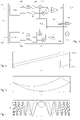
- Figure 7 plots the instantaneous frequency profile of a part of the first projection vector 307. Individual symbol corrections are not appreciable at this scale.
- the receiver synthesizes also an advanced projection vector 305 and a delayed projection vector 309 that are a time-shifted copy of the first vector.
- the time shift in figure 7 is greatly exaggerated, and usually amounts to one sample (8 ⁇ s) or a few samples. In scale, the shift could be 1/128th or 1/4096th of the width of a symbol.
- the invention is not limited to three projection vectors, however: a larger number could be synthesized.
- the projection of the received signal along any of the projection vectors is the accumulated sum of the product of the corresponding samples (an inner product).
- this projection yields only the first complex coefficient of the transform.
- the projections along the advanced and retarded vectors provide the nearby coefficients. One obtains in this manner, an information on the very first coefficients of the Fourier transform.
- the time shift is given by the peak's position in the spectrum of the signal multiplied by the conjugate. After the preliminary synchronization, it is expected that the time shift be less than one sampling period. Therefore, the knowledge of the three lowest-frequency spectral components is in general sufficient for determining the peak position by interpolation.
- multiplying and accumulating the received signal by several, slightly shifted, projection vectors can be regarded as a convenient manner to extract the spectral information of interest without performing a full Fourier transform.
- the above-outlined method allows the determination of a frequency difference of the order of a few Hz between the received signal and the local one, which is adequate for precision synchronization. Still, the inventor have frequently observed that the determination is less reliable in presence of multipath. The reason is that the received signal is in fact a superposition of different exponentials, one for each path.
- Figure 8 illustrates this situation.
- the line 419 indicates a frequency at which two path interfere destructively.
- the invention addresses this situation by dividing the whole bandwidth in sub-bands 415a, 415b and performing the timing process in each sub-band separately. This can be done by slicing the input buffer in time segments, or by selectively nulling portions of the projection vectors.
- Each sub-band provides an independent determination of the time of arrival. Very often, these partial measures are superior to the timing that can be obtained on the whole band. The reason being that, the destructive interference introduces a change of sign in the phase, and the degradation on the timing is maximal when the frequency of maximal interference is in the centre of the band. Since the signal bandwidth is lower than the channel coherence bandwidth, it is highly unlikely to experience more than one phase inversion within a symbol.
- Sub-band 415b is a candidate for exclusion.
- a possible multipath discrimination process can be outlined as follows: For each sub-band 415a-c a timing process is performed, and the interpolation step provides, for each sub-band, an estimate of the position and of the amplitude of the correlation peak. The full band is processed in the same manner and amplitude and position for the full-band correlation peak are obtained as well. Since sub-band inner products are partial sums of the complete inner product, the latter can be obtained directly from the sub-band inner products without iterating on the vector factors again. Therefore, full amplitude and position can be computed at the only extra cost of one interpolation which, in terms of complexity, is much less demanding.
- the absolute interpolated amplitudes of sub-bands essentially sum up to the absolute interpolated amplitude of the full band. This is because when there is no phase inversion, since the channel is slowly moving versus frequency, its phase derivative is almost constant. Then the interpolated delay corresponds to a projection vector aligned with the received signal. When a phase inversion is present, absolute amplitudes do not sum-up anymore, and the sum of absolute amplitude of sub bands will be higher than the absolute amplitude of full band. The same applies to sub divisions of sub bands. This allows detecting the occurrence of such a phase inversion based on the amplitude of the received signal in the sub-bands.
- the sub-band processing of the invention is highly reliable because it takes benefit of the processing gain of the system. With 2 sub bands, the processing gain is just 3dB lower than the processing gain of the full band. The processing gain of the full band is between 15dB and 36dB, depending on spreading factor. This method has proven superior to known blind channel equalization methods, in particular for long-range transmission where LoRa signal can be several dB below the noise floor.
- the sub-band division of this method is equivalent to a time division.
- the sub-bands 415a and 415b split each of the symbols 411a-f into two sub-symbols of same size.
- the algorithm of the invention could be also described in term of sub-symbol, wherein each of the received symbols 411a-411f is divided in sub-symbols, and the multiplication of the projection vectors by the received vector is carried out in each of the sub-symbols.
Landscapes
- Engineering & Computer Science (AREA)
- Signal Processing (AREA)
- Physics & Mathematics (AREA)
- General Physics & Mathematics (AREA)
- Radar, Positioning & Navigation (AREA)
- Remote Sensing (AREA)
- Computer Networks & Wireless Communication (AREA)
- Position Fixing By Use Of Radio Waves (AREA)
- Synchronisation In Digital Transmission Systems (AREA)
Claims (11)
- Procédé de temporisation, dans un récepteur, d'un signal radio généré dans et transmis par un émetteur, le signal radio comprenant une série de chirps de fréquence, le procédé comprenant :- réception du signal radio de l'émetteur; caractérisé par- synthétiser de vecteurs projection comprenant une série de chirps de fréquence qui sont imaginaires conjugués de ceux compris dans le signal radio, les vecteurs projection étant décalés les uns par rapport aux autres par des intervalles temporels déterminés;- calculer pour chaque vecteur projection une projection du signal reçu consistant en la somme accumulé des produits d'échantillons correspondants du signal reçu et du vecteur projection, le vecteur projection comprenant une pluralité de chirps et l'opération de calculer une projection s'étend sur plusieurs chirps du signal radio reçu;- interpoler les projections pour déterminer un décalage temporel de pic, déterminant un instant de réception et un décalage fréquentiel entre un référentiel temporel local compris dans le récepteur un référentiel temporel de l'émetteur, sur la base di décalage temporel de pic, et compenser une pente fréquentielle et une phase des chirps dans les vecteurs de projection sur la base du décalage temporel de pic.
- Le procédé de la revendication précédente, comprenant la réception du signal radio dans une pluralité de récepteur écartés, dans lequel les récepteurs ont accès à un référentiel temporel commun ou bien à une pluralité de référentiels temporels synchronisés, et l'estime d'un vecteur vitesse de l'émetteur radio sur la base des valeurs de synchronisation de fréquence déterminés par les récepteurs.
- Le procédé de l'une quelconque des revendications précédentes, dans lequel une largeur de bande du signal reçu est partitionnée en sous-bandes, la multiplication des vecteurs de projection par les vecteurs reçus étant faite dans chacune des sous-bandes.
- Le procédé de la revendication précédente, comprenant une combinaison entre résultats des sous-bandes et résultat de la bande entière, comprenant une réjection d'une quelconque de ces résultats sur la base d'une estime de l'effet multipath.
- Le procédé de la revendication précédente, dans lequel l'effet multipath est estimé sur la base d'amplitudes du signal reçu dans les sous-bandes.
- Le procédé de l'une quelconque des revendications précédentes, comprenant le stockage d'une représentation numérique du signal radio reçu, dans lequel les opérations de multiplication des vecteurs projection du signal radio reçu est faite sur la représentation numérique stockée.
- Le procédé de l'une quelconque des revendications précédentes, dans lequel les vecteurs projection comprennent un premier vecteur projection aligné avec le signal radio reçu, un second vecteur projection anticipé par rapport au signal radio reçu, un troisième vecteur projection retardé par rapport au signal radio reçu.
- Le procédé de l'une quelconque des revendications précédentes, comprenant la sélection d'un préambule comprenant une pluralité de chirps identiques dans le signal radio.
- Le procédé de l'une quelconque des revendications précédentes, dans lequel les pentes des chirps fréquentiels dans les vecteurs de projection sont adaptées pour correspondre à une fréquence instantanée estimée de l'émetteur.
- Un procédé de positionnement d'un émetteur radio, dans lequel l'émetteur émet un signal radio comprenant une série de chirps fréquentiels dont les paramètres de fréquence, pente et phase sont déterminés, comprenant :- réception du signal radio par une pluralité de récepteurs écartés, dans lequel les récepteurs ont accès à un référentiel temporel commun ou bien à une pluralité de référentiels temporels synchronisés,- détermination des temps d'arrivée du signal radio aux récepteurs par le procédé de l'une quelconque des revendications précédentes,- positionnement de l'émetteur sur la base des temps d'arrivée.
- Le procédé de la revendication précédente, comprenant une estime de la vitesse de l'émetteur radio sur la base des valeurs de synchronisation fréquentielle déterminés aux récepteurs.
Priority Applications (4)
| Application Number | Priority Date | Filing Date | Title |
|---|---|---|---|
| EP16180271.5A EP3273607B1 (fr) | 2016-07-20 | 2016-07-20 | Procédé et système de synchronisation et de localisation d'un signal radio |
| US15/625,560 US10746845B2 (en) | 2016-07-20 | 2017-06-16 | Method and system of timing and localizing a radio signal |
| KR1020170089421A KR102132152B1 (ko) | 2016-07-20 | 2017-07-14 | 무선 신호의 타이밍 및 로컬라이징 방법 및 시스템 |
| CN201710590891.4A CN107645465B (zh) | 2016-07-20 | 2017-07-19 | 对无线电信号进行定时和定位的方法和系统 |
Applications Claiming Priority (1)
| Application Number | Priority Date | Filing Date | Title |
|---|---|---|---|
| EP16180271.5A EP3273607B1 (fr) | 2016-07-20 | 2016-07-20 | Procédé et système de synchronisation et de localisation d'un signal radio |
Publications (2)
| Publication Number | Publication Date |
|---|---|
| EP3273607A1 EP3273607A1 (fr) | 2018-01-24 |
| EP3273607B1 true EP3273607B1 (fr) | 2023-01-18 |
Family
ID=56571141
Family Applications (1)
| Application Number | Title | Priority Date | Filing Date |
|---|---|---|---|
| EP16180271.5A Active EP3273607B1 (fr) | 2016-07-20 | 2016-07-20 | Procédé et système de synchronisation et de localisation d'un signal radio |
Country Status (4)
| Country | Link |
|---|---|
| US (1) | US10746845B2 (fr) |
| EP (1) | EP3273607B1 (fr) |
| KR (1) | KR102132152B1 (fr) |
| CN (1) | CN107645465B (fr) |
Families Citing this family (19)
| Publication number | Priority date | Publication date | Assignee | Title |
|---|---|---|---|---|
| US10079616B2 (en) | 2014-12-19 | 2018-09-18 | University Of Washington | Devices and methods for backscatter communication using one or more wireless communication protocols including bluetooth low energy examples |
| EP3335432B1 (fr) | 2015-08-12 | 2024-02-14 | University of Washington | Dispositifs de rétrodiffusion et systèmes de réseau incorporant des dispositifs de rétrodiffusion |
| US10652073B2 (en) | 2016-04-04 | 2020-05-12 | University Of Washington | Backscatter devices and systems providing backscattered signals including OFDM packets |
| WO2018075653A1 (fr) * | 2016-10-18 | 2018-04-26 | University Of Washington | Systèmes, dispositifs et techniques de rétrodiffusion utilisant une modulation css et/ou une suppression d'harmoniques d'ordre supérieur |
| EP3607429A4 (fr) | 2017-04-06 | 2021-01-06 | The University of Washington | Transmission d'image et/ou de vidéo à l'aide de dispositifs de rétrodiffusion |
| KR102603561B1 (ko) | 2017-09-18 | 2023-11-20 | 셈테크 코포레이션 | 무선 전력 송신 및 통신을 위한 시스템 및 방법 |
| US11276938B2 (en) | 2018-01-11 | 2022-03-15 | Semtech Corporation | Single layer antenna |
| CN108594214B (zh) * | 2018-04-17 | 2022-03-22 | 西安电子科技大学 | 基于fpga的参数可调的线性调频信号产生装置及其产生方法 |
| CN108494885A (zh) * | 2018-05-15 | 2018-09-04 | 北京建工四建工程建设有限公司 | 一种基于LoRa的超高层建筑施工过程监测方法及系统 |
| US10327221B1 (en) | 2018-05-25 | 2019-06-18 | Apple Inc. | Super-resolution technique for time-of-arrival estimation |
| CN109121126B (zh) | 2018-08-10 | 2021-08-17 | Oppo广东移动通信有限公司 | 电子设备、消息推送方法及相关产品 |
| US10921436B2 (en) * | 2018-08-13 | 2021-02-16 | Nxp B.V. | MIMO radar coding for resolving velocity ambiguity |
| CN109166578B (zh) | 2018-08-14 | 2021-05-11 | Oppo广东移动通信有限公司 | 移动终端、语音控制方法及相关产品 |
| CN110430156B (zh) * | 2019-08-14 | 2021-06-01 | 北京智芯微电子科技有限公司 | 突发ofdm数据传输的帧同步方法及系统 |
| EP3836409A1 (fr) * | 2019-12-11 | 2021-06-16 | Semtech Corporation | Radio longue portée à faible puissance |
| WO2021134608A1 (fr) * | 2019-12-31 | 2021-07-08 | 华为技术有限公司 | Procédé et appareil de transmission de signal |
| FR3109681B1 (fr) * | 2020-04-23 | 2023-01-06 | Univ Bordeaux | Procédé d’estimation d’au moins une information de synchronisation d’un signal comprenant une pluralité de chirps, produit programme d’ordinateur et dispositif correspondants. |
| CN114355284B (zh) * | 2022-01-04 | 2023-05-05 | 电子科技大学 | 一种利用频谱主分量的时差估计方法 |
| CN114245455B (zh) * | 2022-01-06 | 2023-04-07 | 吉林大学 | 一种基于LoRa技术的无线定位时间同步方法 |
Family Cites Families (25)
| Publication number | Priority date | Publication date | Assignee | Title |
|---|---|---|---|---|
| US5604765A (en) * | 1994-12-23 | 1997-02-18 | Stanford Telecommunications, Inc. | Position enhanced communication system including system for embedding CDMA navigation beacons under the communications signals of a wireless communication system |
| JPH09307526A (ja) * | 1996-05-17 | 1997-11-28 | Mitsubishi Electric Corp | デジタル放送受信機 |
| EP2259534B1 (fr) * | 1997-11-05 | 2014-08-06 | Sony Deutschland Gmbh | Synchronisation dans des systèmes de communication numériques |
| US6133873A (en) * | 1998-06-03 | 2000-10-17 | Krasner; Norman F. | Method and apparatus for adaptively processing GPS signals in a GPS receiver |
| US6304619B1 (en) * | 1998-07-01 | 2001-10-16 | Zenith Electronics Corporation | Receiver synchronizer |
| DE19961777A1 (de) * | 1999-12-21 | 2001-07-12 | Rudolf Bannasch | Verfahren und Vorrichtungen zur Informationsübertragung |
| US20030043947A1 (en) * | 2001-05-17 | 2003-03-06 | Ephi Zehavi | GFSK receiver |
| US7831004B2 (en) * | 2006-06-13 | 2010-11-09 | Panasonic Corporation | Synchronous detecting circuit |
| US7456785B2 (en) * | 2006-11-29 | 2008-11-25 | Transcore Link Logistics Corporation | Navigation signal differential acquisition method and systems therefor |
| FR2914430B1 (fr) * | 2007-03-29 | 2011-03-04 | Centre Nat Detudes Spatiales Cnes | Procede de traitement de signaux de radionavigation. |
| US9088348B2 (en) * | 2007-06-18 | 2015-07-21 | Digi International Inc. | System and method for obtaining frequency and time synchronization in a wideband communication system |
| US8077820B2 (en) * | 2008-03-05 | 2011-12-13 | Agere Systems Inc. | Detection of frequency correction bursts and the like |
| EP2278724A1 (fr) * | 2009-07-02 | 2011-01-26 | Nanoscale Labs | Système de communication |
| US8582698B2 (en) * | 2010-05-10 | 2013-11-12 | Telefonaktiebolaget Lm Ericsson (Publ) | Reduced complexity timing estimation for locating the position of a mobile terminal |
| US8976060B2 (en) * | 2011-05-23 | 2015-03-10 | Digi International Inc. | RF chirp signal propagation delay measurement |
| GB2494129B (en) * | 2011-08-30 | 2018-01-10 | Qualcomm Technologies Int Ltd | Chirp receiver |
| US8861568B2 (en) * | 2011-11-22 | 2014-10-14 | Novatel Inc. | Chirp receiver utilizing phase processed chirp signals |
| US8867588B2 (en) * | 2012-08-31 | 2014-10-21 | Cambridge Silicon Radio Limited | Chirp data channel synchronisation |
| EP2767847B1 (fr) | 2013-02-14 | 2016-04-20 | Semtech Corporation | Système de positionnement et de télémétrie |
| US9083444B2 (en) * | 2013-03-12 | 2015-07-14 | Digi International Inc. | Chirp spread spectrum system and method |
| US9766321B2 (en) * | 2013-03-14 | 2017-09-19 | Digi International Inc. | Indoor positioning with radio frequency chirp signal propagation delay measurement |
| US9326295B1 (en) * | 2014-12-10 | 2016-04-26 | Sony Corporation | Method and apparatus for transmitting a-priori information in a communication system |
| EP3208946B1 (fr) * | 2015-03-03 | 2021-05-05 | Semtech Corporation | Procédé et dispositif de communication dans la bande cellulaire |
| US9419785B1 (en) * | 2015-04-28 | 2016-08-16 | National Central University | Initial synchronization method and apparatus assisted by inherent diversity over time-varying frequency-selective fading channels |
| FR3052615B1 (fr) * | 2016-06-09 | 2019-11-01 | B-Com | Procede de demodulation d'un signal recu, produit programme d'ordinateur et dispositif correspondants |
-
2016
- 2016-07-20 EP EP16180271.5A patent/EP3273607B1/fr active Active
-
2017
- 2017-06-16 US US15/625,560 patent/US10746845B2/en active Active
- 2017-07-14 KR KR1020170089421A patent/KR102132152B1/ko active IP Right Grant
- 2017-07-19 CN CN201710590891.4A patent/CN107645465B/zh active Active
Also Published As
| Publication number | Publication date |
|---|---|
| KR20180010141A (ko) | 2018-01-30 |
| KR102132152B1 (ko) | 2020-07-09 |
| CN107645465B (zh) | 2020-12-15 |
| EP3273607A1 (fr) | 2018-01-24 |
| CN107645465A (zh) | 2018-01-30 |
| US20180024224A1 (en) | 2018-01-25 |
| US10746845B2 (en) | 2020-08-18 |
Similar Documents
| Publication | Publication Date | Title |
|---|---|---|
| EP3273607B1 (fr) | Procédé et système de synchronisation et de localisation d'un signal radio | |
| US10823834B2 (en) | Ranging and positioning system | |
| US9295021B2 (en) | Measurement of time of arrival | |
| US20190033423A1 (en) | Determining the Position of a Mobile Device Using the Characteristics of Received Signals and a Reference Database | |
| US8314736B2 (en) | Determining the position of a mobile device using the characteristics of received signals and a reference database | |
| US9310464B2 (en) | Determining location of a receiver with a multi-subcarrier signal | |
| US20160094270A1 (en) | Synchronization apparatus and method | |
| US20100141520A1 (en) | Method for the acquisition of signals of a global navigation satellite system | |
| US11294024B2 (en) | System, apparatus, and/or method for determining a time of flight for one or more receivers and transmitters | |
| Ghany et al. | A robustness comparison of measured narrowband CSI vs RSSI for IoT localization | |
| CN117060985B (zh) | 一种船载双天线pcma系统信号重捕方法及装置 | |
| US20220187443A1 (en) | Doppler ranging system | |
| US20200383070A1 (en) | System and Method to Enhance Ranging Resolution for Localization of a Lora Sensor or Device | |
| Kremo et al. | A method to enhance ranging resolution for localization of LoRa sensors | |
| CN117761673A (zh) | 一种基于ofdm信号对微动目标位移测量的方法和系统 |
Legal Events
| Date | Code | Title | Description |
|---|---|---|---|
| PUAI | Public reference made under article 153(3) epc to a published international application that has entered the european phase |
Free format text: ORIGINAL CODE: 0009012 |
|
| STAA | Information on the status of an ep patent application or granted ep patent |
Free format text: STATUS: THE APPLICATION HAS BEEN PUBLISHED |
|
| AK | Designated contracting states |
Kind code of ref document: A1 Designated state(s): AL AT BE BG CH CY CZ DE DK EE ES FI FR GB GR HR HU IE IS IT LI LT LU LV MC MK MT NL NO PL PT RO RS SE SI SK SM TR |
|
| AX | Request for extension of the european patent |
Extension state: BA ME |
|
| STAA | Information on the status of an ep patent application or granted ep patent |
Free format text: STATUS: REQUEST FOR EXAMINATION WAS MADE |
|
| 17P | Request for examination filed |
Effective date: 20180620 |
|
| RBV | Designated contracting states (corrected) |
Designated state(s): AL AT BE BG CH CY CZ DE DK EE ES FI FR GB GR HR HU IE IS IT LI LT LU LV MC MK MT NL NO PL PT RO RS SE SI SK SM TR |
|
| STAA | Information on the status of an ep patent application or granted ep patent |
Free format text: STATUS: EXAMINATION IS IN PROGRESS |
|
| 17Q | First examination report despatched |
Effective date: 20200430 |
|
| STAA | Information on the status of an ep patent application or granted ep patent |
Free format text: STATUS: EXAMINATION IS IN PROGRESS |
|
| GRAP | Despatch of communication of intention to grant a patent |
Free format text: ORIGINAL CODE: EPIDOSNIGR1 |
|
| STAA | Information on the status of an ep patent application or granted ep patent |
Free format text: STATUS: GRANT OF PATENT IS INTENDED |
|
| INTG | Intention to grant announced |
Effective date: 20220927 |
|
| GRAS | Grant fee paid |
Free format text: ORIGINAL CODE: EPIDOSNIGR3 |
|
| GRAA | (expected) grant |
Free format text: ORIGINAL CODE: 0009210 |
|
| STAA | Information on the status of an ep patent application or granted ep patent |
Free format text: STATUS: THE PATENT HAS BEEN GRANTED |
|
| AK | Designated contracting states |
Kind code of ref document: B1 Designated state(s): AL AT BE BG CH CY CZ DE DK EE ES FI FR GB GR HR HU IE IS IT LI LT LU LV MC MK MT NL NO PL PT RO RS SE SI SK SM TR |
|
| REG | Reference to a national code |
Ref country code: GB Ref legal event code: FG4D |
|
| REG | Reference to a national code |
Ref country code: DE Ref legal event code: R096 Ref document number: 602016077488 Country of ref document: DE |
|
| REG | Reference to a national code |
Ref country code: CH Ref legal event code: EP |
|
| REG | Reference to a national code |
Ref country code: AT Ref legal event code: REF Ref document number: 1545228 Country of ref document: AT Kind code of ref document: T Effective date: 20230215 Ref country code: IE Ref legal event code: FG4D |
|
| REG | Reference to a national code |
Ref country code: LT Ref legal event code: MG9D |
|
| REG | Reference to a national code |
Ref country code: NL Ref legal event code: MP Effective date: 20230118 |
|
| REG | Reference to a national code |
Ref country code: AT Ref legal event code: MK05 Ref document number: 1545228 Country of ref document: AT Kind code of ref document: T Effective date: 20230118 |
|
| PG25 | Lapsed in a contracting state [announced via postgrant information from national office to epo] |
Ref country code: NL Free format text: LAPSE BECAUSE OF FAILURE TO SUBMIT A TRANSLATION OF THE DESCRIPTION OR TO PAY THE FEE WITHIN THE PRESCRIBED TIME-LIMIT Effective date: 20230118 |
|
| P01 | Opt-out of the competence of the unified patent court (upc) registered |
Effective date: 20230530 |
|
| PG25 | Lapsed in a contracting state [announced via postgrant information from national office to epo] |
Ref country code: RS Free format text: LAPSE BECAUSE OF FAILURE TO SUBMIT A TRANSLATION OF THE DESCRIPTION OR TO PAY THE FEE WITHIN THE PRESCRIBED TIME-LIMIT Effective date: 20230118 Ref country code: PT Free format text: LAPSE BECAUSE OF FAILURE TO SUBMIT A TRANSLATION OF THE DESCRIPTION OR TO PAY THE FEE WITHIN THE PRESCRIBED TIME-LIMIT Effective date: 20230518 Ref country code: NO Free format text: LAPSE BECAUSE OF FAILURE TO SUBMIT A TRANSLATION OF THE DESCRIPTION OR TO PAY THE FEE WITHIN THE PRESCRIBED TIME-LIMIT Effective date: 20230418 Ref country code: LV Free format text: LAPSE BECAUSE OF FAILURE TO SUBMIT A TRANSLATION OF THE DESCRIPTION OR TO PAY THE FEE WITHIN THE PRESCRIBED TIME-LIMIT Effective date: 20230118 Ref country code: LT Free format text: LAPSE BECAUSE OF FAILURE TO SUBMIT A TRANSLATION OF THE DESCRIPTION OR TO PAY THE FEE WITHIN THE PRESCRIBED TIME-LIMIT Effective date: 20230118 Ref country code: HR Free format text: LAPSE BECAUSE OF FAILURE TO SUBMIT A TRANSLATION OF THE DESCRIPTION OR TO PAY THE FEE WITHIN THE PRESCRIBED TIME-LIMIT Effective date: 20230118 Ref country code: ES Free format text: LAPSE BECAUSE OF FAILURE TO SUBMIT A TRANSLATION OF THE DESCRIPTION OR TO PAY THE FEE WITHIN THE PRESCRIBED TIME-LIMIT Effective date: 20230118 Ref country code: AT Free format text: LAPSE BECAUSE OF FAILURE TO SUBMIT A TRANSLATION OF THE DESCRIPTION OR TO PAY THE FEE WITHIN THE PRESCRIBED TIME-LIMIT Effective date: 20230118 |
|
| PG25 | Lapsed in a contracting state [announced via postgrant information from national office to epo] |
Ref country code: SE Free format text: LAPSE BECAUSE OF FAILURE TO SUBMIT A TRANSLATION OF THE DESCRIPTION OR TO PAY THE FEE WITHIN THE PRESCRIBED TIME-LIMIT Effective date: 20230118 Ref country code: PL Free format text: LAPSE BECAUSE OF FAILURE TO SUBMIT A TRANSLATION OF THE DESCRIPTION OR TO PAY THE FEE WITHIN THE PRESCRIBED TIME-LIMIT Effective date: 20230118 Ref country code: IS Free format text: LAPSE BECAUSE OF FAILURE TO SUBMIT A TRANSLATION OF THE DESCRIPTION OR TO PAY THE FEE WITHIN THE PRESCRIBED TIME-LIMIT Effective date: 20230518 Ref country code: GR Free format text: LAPSE BECAUSE OF FAILURE TO SUBMIT A TRANSLATION OF THE DESCRIPTION OR TO PAY THE FEE WITHIN THE PRESCRIBED TIME-LIMIT Effective date: 20230419 Ref country code: FI Free format text: LAPSE BECAUSE OF FAILURE TO SUBMIT A TRANSLATION OF THE DESCRIPTION OR TO PAY THE FEE WITHIN THE PRESCRIBED TIME-LIMIT Effective date: 20230118 |
|
| REG | Reference to a national code |
Ref country code: DE Ref legal event code: R097 Ref document number: 602016077488 Country of ref document: DE |
|
| PG25 | Lapsed in a contracting state [announced via postgrant information from national office to epo] |
Ref country code: SM Free format text: LAPSE BECAUSE OF FAILURE TO SUBMIT A TRANSLATION OF THE DESCRIPTION OR TO PAY THE FEE WITHIN THE PRESCRIBED TIME-LIMIT Effective date: 20230118 Ref country code: RO Free format text: LAPSE BECAUSE OF FAILURE TO SUBMIT A TRANSLATION OF THE DESCRIPTION OR TO PAY THE FEE WITHIN THE PRESCRIBED TIME-LIMIT Effective date: 20230118 Ref country code: EE Free format text: LAPSE BECAUSE OF FAILURE TO SUBMIT A TRANSLATION OF THE DESCRIPTION OR TO PAY THE FEE WITHIN THE PRESCRIBED TIME-LIMIT Effective date: 20230118 Ref country code: DK Free format text: LAPSE BECAUSE OF FAILURE TO SUBMIT A TRANSLATION OF THE DESCRIPTION OR TO PAY THE FEE WITHIN THE PRESCRIBED TIME-LIMIT Effective date: 20230118 Ref country code: CZ Free format text: LAPSE BECAUSE OF FAILURE TO SUBMIT A TRANSLATION OF THE DESCRIPTION OR TO PAY THE FEE WITHIN THE PRESCRIBED TIME-LIMIT Effective date: 20230118 |
|
| PGFP | Annual fee paid to national office [announced via postgrant information from national office to epo] |
Ref country code: GB Payment date: 20230727 Year of fee payment: 8 |
|
| PLBE | No opposition filed within time limit |
Free format text: ORIGINAL CODE: 0009261 |
|
| STAA | Information on the status of an ep patent application or granted ep patent |
Free format text: STATUS: NO OPPOSITION FILED WITHIN TIME LIMIT |
|
| PG25 | Lapsed in a contracting state [announced via postgrant information from national office to epo] |
Ref country code: SK Free format text: LAPSE BECAUSE OF FAILURE TO SUBMIT A TRANSLATION OF THE DESCRIPTION OR TO PAY THE FEE WITHIN THE PRESCRIBED TIME-LIMIT Effective date: 20230118 |
|
| PGFP | Annual fee paid to national office [announced via postgrant information from national office to epo] |
Ref country code: FR Payment date: 20230725 Year of fee payment: 8 Ref country code: DE Payment date: 20230727 Year of fee payment: 8 |
|
| 26N | No opposition filed |
Effective date: 20231019 |
|
| PG25 | Lapsed in a contracting state [announced via postgrant information from national office to epo] |
Ref country code: SI Free format text: LAPSE BECAUSE OF FAILURE TO SUBMIT A TRANSLATION OF THE DESCRIPTION OR TO PAY THE FEE WITHIN THE PRESCRIBED TIME-LIMIT Effective date: 20230118 |
|
| PG25 | Lapsed in a contracting state [announced via postgrant information from national office to epo] |
Ref country code: MC Free format text: LAPSE BECAUSE OF FAILURE TO SUBMIT A TRANSLATION OF THE DESCRIPTION OR TO PAY THE FEE WITHIN THE PRESCRIBED TIME-LIMIT Effective date: 20230118 |
|
| PG25 | Lapsed in a contracting state [announced via postgrant information from national office to epo] |
Ref country code: MC Free format text: LAPSE BECAUSE OF FAILURE TO SUBMIT A TRANSLATION OF THE DESCRIPTION OR TO PAY THE FEE WITHIN THE PRESCRIBED TIME-LIMIT Effective date: 20230118 |
|
| REG | Reference to a national code |
Ref country code: CH Ref legal event code: PL |
|
| REG | Reference to a national code |
Ref country code: BE Ref legal event code: MM Effective date: 20230731 |
|
| PG25 | Lapsed in a contracting state [announced via postgrant information from national office to epo] |
Ref country code: LU Free format text: LAPSE BECAUSE OF NON-PAYMENT OF DUE FEES Effective date: 20230720 |
|
| PG25 | Lapsed in a contracting state [announced via postgrant information from national office to epo] |
Ref country code: LU Free format text: LAPSE BECAUSE OF NON-PAYMENT OF DUE FEES Effective date: 20230720 |
|
| REG | Reference to a national code |
Ref country code: IE Ref legal event code: MM4A |
|
| PG25 | Lapsed in a contracting state [announced via postgrant information from national office to epo] |
Ref country code: CH Free format text: LAPSE BECAUSE OF NON-PAYMENT OF DUE FEES Effective date: 20230731 |
|
| PG25 | Lapsed in a contracting state [announced via postgrant information from national office to epo] |
Ref country code: IT Free format text: LAPSE BECAUSE OF FAILURE TO SUBMIT A TRANSLATION OF THE DESCRIPTION OR TO PAY THE FEE WITHIN THE PRESCRIBED TIME-LIMIT Effective date: 20230118 Ref country code: BE Free format text: LAPSE BECAUSE OF NON-PAYMENT OF DUE FEES Effective date: 20230731 |
|
| PG25 | Lapsed in a contracting state [announced via postgrant information from national office to epo] |
Ref country code: IE Free format text: LAPSE BECAUSE OF NON-PAYMENT OF DUE FEES Effective date: 20230720 |
|
| PG25 | Lapsed in a contracting state [announced via postgrant information from national office to epo] |
Ref country code: IE Free format text: LAPSE BECAUSE OF NON-PAYMENT OF DUE FEES Effective date: 20230720 |