EP3273201B2 - Methode de calcul d'un itineraire pour un engin tout terrain - Google Patents
Methode de calcul d'un itineraire pour un engin tout terrain Download PDFInfo
- Publication number
- EP3273201B2 EP3273201B2 EP17182421.2A EP17182421A EP3273201B2 EP 3273201 B2 EP3273201 B2 EP 3273201B2 EP 17182421 A EP17182421 A EP 17182421A EP 3273201 B2 EP3273201 B2 EP 3273201B2
- Authority
- EP
- European Patent Office
- Prior art keywords
- vehicle
- terrain
- itinerary
- trafficability
- route
- Prior art date
- Legal status (The legal status is an assumption and is not a legal conclusion. Google has not performed a legal analysis and makes no representation as to the accuracy of the status listed.)
- Active
Links
Images

Classifications
-
- G—PHYSICS
- G01—MEASURING; TESTING
- G01C—MEASURING DISTANCES, LEVELS OR BEARINGS; SURVEYING; NAVIGATION; GYROSCOPIC INSTRUMENTS; PHOTOGRAMMETRY OR VIDEOGRAMMETRY
- G01C21/00—Navigation; Navigational instruments not provided for in groups G01C1/00 - G01C19/00
- G01C21/20—Instruments for performing navigational calculations
Definitions
- the invention relates to a method for calculating a route for an all-terrain vehicle.
- some sophisticated software can establish a route between a starting point and an arrival point based on cartographic data, particularly from satellite images.
- the software begins by establishing a crossing zone, or "geofence" in English, extending between the starting point and the arrival point. This zone defines all possible routes to go from the starting point to the arrival point. Areas that are difficult or even impossible to cross, such as areas with relief, dense vegetation, or areas crossed by rivers, are excluded from the crossing zone.
- the software calculates a route for the machine to follow. This route is calculated to make it as easy as possible for the machine to pass. However, this route is not necessarily the shortest or the one with the shortest travel time.
- Satellite images are updated on average every few days.
- maps produced from satellite images do not allow for the identification of possible obstacles formed a few hours before the vehicle passes, such as landslides on the track or the overflowing of a watercourse, nor do they take into account certain major climatic events, such as snowfall.
- the accuracy of the maps does not allow for the identification of obstacles such as a tree lying on the track.
- satellite images do not allow for the precise determination of bearing and grip capacities. Often, these capacities are estimated based on rainfall data in the area concerned.
- one solution is to equip the machine with presence sensors for obstacle detection.
- the range of these sensors is often limited by the natural masks formed by the terrain (reliefs), which does not allow the obstacle to be anticipated sufficiently. The obstacle is then detected at the last moment. The aforementioned U-turn maneuvers cannot then be avoided.
- Another solution is to carry out preliminary on-site observations relating to the topography of the terrain (presence of a watercourse, a ravine, etc.), as well as penetrometer tests on all the terrain crossed by the route.
- this requires mobilizing a large number of operators, which is long, costly and unsuitable for risk areas.
- a reconnaissance vehicle is known per se, in particular from the document CN-A-105 282 517 , in which a drone is used to assist firefighters in a burning area.
- the drone is equipped with means to monitor the spread of the fire, which helps prevent firefighters from becoming surrounded by flames.
- US-A-2014 263 822 discloses the use of a drone for agriculture. This drone is equipped with measuring means with which it is possible to estimate the water content of agricultural land. The drone thus makes it possible to list the wetter areas, and the more arid areas requiring more irrigation.
- the method presented in this document does not take into account the nature of the obstacle.
- the trajectory is modified even if the vehicle was a priori able to cross the obstacle, which potentially results in a loss of time and an increase in travel time.
- the invention more particularly intends to remedy by proposing a new method of calculating a route for an all-terrain vehicle, making it possible to modify the route more intelligently depending on the nature of the obstacle(s) detected on the path of the vehicle and therefore not to increase the journey time unnecessarily.
- the invention relates to a method according to claim 1.
- the reconnaissance vehicle preceding the all-terrain vehicle can detect the presence of an obstacle on the route of the all-terrain vehicle that had not been identified when establishing the route from the cartographic data or that was too small to be visible from satellite images.
- the sensors on board the reconnaissance vehicle make it possible to determine with greater precision the properties of the terrain (bearing capacity, grip, etc.) taken by the route. It is then possible to anticipate difficulties for the vehicle to cross at certain points on the route. This is the case, for example, when the machine is heavy and the ground is soft, or when the chassis-ground connection of the machine is not suitable for low-grip ground, such as snow-covered ground. To do this, the machine's route to reach the arrival point is modified. This route updating procedure can be repeated as many times as necessary depending on the number of obstacles identified by the reconnaissance vehicle.
- the all-terrain vehicle E is capable of moving on any type of terrain (road, track, mud, sand, snow, etc.). It can be a land motor vehicle (LMV) such as a fire engine, a rescue vehicle (firefighters), a military vehicle, a construction vehicle or a heavy truck. It can also be an aircraft during the taxiing, landing and take-off phases.
- LMV land motor vehicle
- the machine E can be autonomous. In this case, the machine E moves automatically without human intervention. Alternatively, the machine can be piloted by a driver on board or remotely controlled. In the case of a vehicle with a driver, the route is then simply a route recommended to the driver to reach the arrival point.
- the invention also applies to a vehicle belonging to a convoy of all-terrain vehicles, in particular to the first vehicle in the convoy, each of the other vehicles following the vehicle in front.
- the route calculation method according to the invention comprises a first step consisting of establishing a route I1 to be followed by the machine E to go from a starting point A to an arrival point B.
- the software begins, in a step 100, by determining a crossing zone G, commonly called a “Geo-fence” in English, which encompasses all the possible trajectories that the machine E can take to go from point A to point B without difficulty.
- the trajectories outside this zone G are therefore the trajectories that cannot be followed by the machine E, at least not within a reasonable time period.
- the software calculates, during a step 102, the route I1 according to the type of machine and the desired performance criteria.
- the chosen route I1 may be the route with the lowest risk of crossing, which has the advantage of limiting the risk of breakage.
- the chosen route I1 may also be the route with the shortest travel time, particularly suitable for fire engines or emergency vehicles (firefighters). It is also possible to calculate a route I1 with fewer stresses or jolts, in particular for vehicles transporting sensitive products or equipment.
- the route I1 is established by dedicated software implemented in a computer not shown.
- the computer may or may not be embedded on the machine E.
- the computer may be common to several machines and communicates the route to be followed to the GPS system of each, for example by radio waves.
- Route I1 is represented by the dashed curve on the figure 1 .
- Route I1 can also be achieved by determining intermediate waypoints.
- the route I1 can be established from a mobile geolocation beacon carried by another machine or by a person. This is particularly the case when it is necessary to guide a machine on a route already taken previously, that is to say, a previous survey of the same area is used. The machine can then follow the same route as a previous machine to go from the same starting point A to the same arrival point B.
- the data provided by one or more geolocation beacons and the cartographic data can also be used in a complementary manner.
- the calculator also establishes passage speeds in each zone crossed by the route.
- these passage speeds are simply recommended speeds.
- the speed of the machine is automatically adjusted according to the terrain taken along the route. Indeed, the machine will not go as fast on a snowy forest track as on a road axis for example.
- the different passage speeds of the machine E along the route I1 are determined from cartographic data and/or at least a known route layout.
- the machine E is preceded by an unmanned reconnaissance vehicle of the autonomous type or of the remotely controlled type. If the reconnaissance vehicle is of the autonomous type, it moves automatically without human intervention.
- the reconnaissance vehicle is a drone D but one can imagine, as a variant, a reconnaissance vehicle in the form of a motorized land vehicle. In the latter case, the reconnaissance vehicle then has a high crossing capacity, that is to say that it can cross any type of ground (soft, snowy, muddy, etc.) without difficulty, compared to the machine E.
- this land reconnaissance vehicle can be designed to be very light.
- the advantage of using a reconnaissance vehicle such as a drone is that, unlike a land vehicle, the range of the measuring means on board the drone is not or only slightly limited by the relief of the terrain (natural masks).
- the distance d which separates the reconnaissance vehicle D and the machine E can be set: it is function of the forward speed of the machine and the route calculation time. Preferably, it is at least 150m, which corresponds to a delay time for the machine of at least 18 seconds, considering that the latter is moving at less than 60 km/h.
- the reconnaissance vehicle D is equipped with a GPS (Global Positioning System) beacon and means of communication with the vehicle E.
- GPS Global Positioning System
- these means of communication include a radio wave transmitter.
- the hyperspectral camera is used to determine the type of vegetation on the ground
- the Lidar laser radar
- the georadar is used to evaluate the compactness of the soil and the cone index (Cl).
- the range of these on-board measuring means combined with the area coverage capacity of the reconnaissance vehicle make it possible to collect data in a cone that is directed at an angle of approximately 45° to the vertical and which has a height of approximately 600m and a base of 1200m in width.
- the measuring range may be different depending on the type of equipment used.
- the precision of the measuring means can be adapted according to the need.
- the reconnaissance vehicle D moves in such a way that its measuring cone remains centered on the trajectory to be followed by the vehicle E, that is to say that the reconnaissance vehicle moves in such a way that the axis of its measuring cone remains substantially tangent to the planned trajectory.
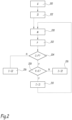
- the data M collected, during a step 200, by the measuring means on board the reconnaissance vehicle D are transmitted in real time to the computer, i.e. dynamically.
- the computer then calculates, during a step 202, values of parameters P relating to the trafficability of the terrain from the measurements M carried out by the reconnaissance vehicle D.
- the values of the P parameters relating to the trafficability of the terrain concern the portion of the route extending over approximately 600 m located approximately 300 m in front of the vehicle E.
- These P parameter values include morphological characteristics of the terrain (clay content, water content, soil composition, etc.), and/or geometric characteristics of the terrain (relief, obstacles, grain size, etc.) and/or mechanical properties of the terrain (bearing capacity, grip, etc.).
- the M data collected by the reconnaissance vehicle make it possible to detect the presence of an obstacle O on the portion of the route I1, this obstacle not being visible from the satellite images.
- This is called a Dynamic Digital Terrain Model (DTM) corresponding to a level 2 terrain analysis (precise local trafficability mapping).
- DTM Dynamic Digital Terrain Model
- the computer is able to estimate, from the values recorded by the reconnaissance vehicle D, the condition of the surface.
- the dynamic digital terrain model makes it possible to establish a dynamic route crossing zone, or more commonly called a “dynamic route geo-fence”.
- the computer calculates the probable average speed V of the vehicle E on the portion of the route extending into the range of the reconnaissance vehicle D. This portion of the route extends approximately, in the example, over 600 m from the position of the reconnaissance vehicle.
- the threshold speed value S can be chosen between 5 and 20 km/h, for example of the order of 10 km/h.
- the threshold speed value S may be chosen to be equal or substantially equal to the originally estimated speed, i.e. the speed calculated from the level 1 terrain analysis for the route portion considered.
- the expression “substantially” means that a tolerance margin may be used.
- the threshold speed S may be chosen to be 10% lower than the passing speed calculated from the level 1 terrain analysis. It is then accepted that the vehicle E travels at a speed slightly lower than that anticipated when calculating the route.
- the threshold speed value S can be equal to the speed originally calculated with the level 1 terrain analysis.
- the calculator can then be used to determine whether the machine has sufficient crossing capabilities to follow the route with different crossing speeds greater than or equal to at least one threshold speed value (the calculator defines the crossing setpoint speeds) and, failing that, to establish a new route I2 to the arrival point based on the cartographic data and/or the values of parameters P relating to the trafficability of the terrain.
- the calculator defines the crossing setpoint speeds
- Each threshold speed value is substantially equal to a passing speed determined from the map data and/or at least one known route layout.
- the calculator is used to determine whether the machine E has sufficient crossing capabilities to follow the route I1 with at least one crossing speed V greater than or equal to at least one threshold speed value S and, failing that, to establish (step 206) a new route I2 to the arrival point B from the cartographic data and/or the values of parameters P relating to the trafficability of the terrain.
- the new route I2 is calculated from the cartographic data (level 1) and, possibly from the values of parameters P relating to the trafficability of the terrain (level 2) calculated using the measurements of the reconnaissance vehicle D. Indeed, the reconnaissance vehicle D can be ordered to explore an area not crossed by the initial route.
- the new route I2 is transmitted by the calculator to the machine's GPS (Global Positioning System).
- GPS Global Positioning System
- the machine only encounters one obstacle O and the route is therefore recalculated only once.
- the route is recalculated as many times as an impassable or difficult-to-pass obstacle is detected on the route of the machine E. Thanks to this method, any obstacle O present on the trajectory of the machine E can be anticipated and easily avoided (without maneuvering) by updating the route.
- the measurement means on board the machine E can be used to compare the values of parameters relating to the trafficability of the terrain, established using the drone D, with the actual trafficability of the terrain.
- the camera on board the machine E can be arranged to estimate the sinking of the machine E into the ground from the tire or track tracks, which makes it possible to calculate the bearing capacity of the ground based on the weight of the machine. It is then possible to calculate a correction coefficient to be applied to the data collected by the reconnaissance vehicle D to refine the Dynamic Digital Terrain Model (DTM-D) established using the reconnaissance vehicle.
- This correction coefficient is calculated from data extracted over one or more dozens, or even one or more hundreds of journeys.
- the purpose of the correction coefficient is to correct the measurements of the reconnaissance vehicle using feedback from one or more previous journeys.
- the measuring means on board the machine can also be used for obstacle detection in the immediate vicinity of the machine E.
- such measuring means can be used in the case where the data collected by the drone D, such as data relating to the characteristics of the terrain (compactness, bearing capacity, grip, etc.), are not reliable enough, for example due to terrain of a very complex nature or the presence of dense vegetation (forest).
- This is referred to as a level 3 terrain analysis.
- Level 3 terrain analysis can also be used to bypass a new unforeseen obstacle, such as a tree lying on the track, not detected by the reconnaissance vehicle D without necessarily changing route or to bypass or cross an obstacle already detected by the reconnaissance vehicle D but for which the position must be more precisely determined to allow it to be bypassed or crossed. This therefore involves taking into account the terrain in very localized terms in front of or around the machine E.
- Tactical data is extracted from a tactical management system or in English "Battle Management System” (BMS). Tactical data can be considered essential for the calculation of the route.
- the route then corresponds to a route with the lowest tactical risk, that is to say a route where the vehicle is least exposed to enemy/allied fire, minefields, or ambushes.
- each of the crossing parameters of the machine is not stored in memory but is communicated by the machine to a computer external to the vehicle.
- the calculator is embedded on the reconnaissance vehicle D.
- level 3 terrain analysis is also taken into account when calculating each new route.
- the route is only modified according to a step 206 if the reconnaissance vehicle detects a blocking obstacle on the route.
- the route is not modified as long as the machine E manages to cross, even if it must adopt a very low speed to do so.
- step 208 is optional.
- the speed of the machine E if the latter is autonomous, will be adapted according to the level 2 terrain analysis, and in particular automatically reduced to cross an unforeseen obstacle, such as a landslide or a tree lying on the track.
- the route I1 can be set manually by a user, such as the driver of the machine E. To do this, the user selects waypoints, i.e. route points to reach in order to reach the arrival point B. The software can then check whether the route established by the user is part of the trajectories included in the crossing zone G calculated in parallel. If this is the case, the route established manually is maintained. On the other hand, if the route established by the user is not entirely part of the crossing zone G, then a new departure route I1 is calculated. It should be noted that if it is not possible to establish a crossing zone, i.e. if there is no cartographic data, or at least no usable cartographic data in the area concerned, then the route established manually by the user is automatically maintained.
- waypoints i.e. route points to reach in order to reach the arrival point B.
- the software can then check whether the route established by the user is part of the trajectories included in the crossing zone G calculated in parallel. If this is the case, the route established manually
- the departure route I1 is calculated on the basis of a straight line connecting points A and B.
- the route may however be modified en route on the basis of the measurements carried out by the reconnaissance vehicle D (Level 2 terrain analysis), i.e. the values of parameters P relating to the trafficability of the terrain.
Landscapes
- Engineering & Computer Science (AREA)
- Radar, Positioning & Navigation (AREA)
- Remote Sensing (AREA)
- Automation & Control Theory (AREA)
- Physics & Mathematics (AREA)
- General Physics & Mathematics (AREA)
- Traffic Control Systems (AREA)
- Navigation (AREA)
- Control Of Driving Devices And Active Controlling Of Vehicle (AREA)
Applications Claiming Priority (1)
| Application Number | Priority Date | Filing Date | Title |
|---|---|---|---|
| FR1656955A FR3054313B1 (fr) | 2016-07-21 | 2016-07-21 | Methode de calcul d'un itineraire pour un engin tout terrain |
Publications (3)
| Publication Number | Publication Date |
|---|---|
| EP3273201A1 EP3273201A1 (fr) | 2018-01-24 |
| EP3273201B1 EP3273201B1 (fr) | 2021-06-30 |
| EP3273201B2 true EP3273201B2 (fr) | 2024-09-04 |
Family
ID=57590584
Family Applications (1)
| Application Number | Title | Priority Date | Filing Date |
|---|---|---|---|
| EP17182421.2A Active EP3273201B2 (fr) | 2016-07-21 | 2017-07-20 | Methode de calcul d'un itineraire pour un engin tout terrain |
Country Status (6)
| Country | Link |
|---|---|
| EP (1) | EP3273201B2 (he) |
| DK (1) | DK3273201T4 (he) |
| ES (1) | ES2882061T5 (he) |
| FI (1) | FI3273201T4 (he) |
| FR (1) | FR3054313B1 (he) |
| IL (1) | IL253514B (he) |
Families Citing this family (5)
| Publication number | Priority date | Publication date | Assignee | Title |
|---|---|---|---|---|
| FR3089456B1 (fr) | 2018-12-05 | 2021-07-16 | Renault Trucks Defense | Ensemble roulant comportant un engin tracteur, au moins une remorque et un système d’attelage automatique de la remorque sur l’engin tracteur |
| JP7240239B2 (ja) * | 2019-04-23 | 2023-03-15 | カワサキモータース株式会社 | 移動支援プログラム、移動支援システムおよび移動支援方法 |
| US11797019B2 (en) | 2020-07-20 | 2023-10-24 | Ford Global Technologies, Llc | Rugged terrain vehicle design and route optimization |
| CN112632750B (zh) * | 2020-12-01 | 2023-09-26 | 北方信息控制研究院集团有限公司 | 虚拟战场环境不同要素相互耦合的仿真建模方法及系统 |
| CN114537057B (zh) * | 2022-03-07 | 2024-01-26 | 哈尔滨工业大学 | 一种应用于金属网胎面的车轮地形识别方法 |
Citations (39)
| Publication number | Priority date | Publication date | Assignee | Title |
|---|---|---|---|---|
| JPS5819555B2 (ja) † | 1974-11-22 | 1983-04-19 | オ−エンス−イリノイ インコ−ポレ−テツド | 容器のラベル添着方法およびラベル用スリ−ブ材を形成する装置 |
| EP0838797A1 (de) † | 1996-10-26 | 1998-04-29 | Philips Patentverwaltung GmbH | Navigationssystem für ein Landfahrzeug |
| EP0908087A1 (de) † | 1997-10-09 | 1999-04-14 | CLAAS Selbstfahrende Erntemaschinen GmbH | Feuchtemesseinrichtung und Verfahren zur Feuchtemessung in Erntemaschinen |
| DE19956108A1 (de) † | 1999-11-22 | 2001-05-23 | Mannesmann Vdo Ag | Verfahren zur dynamischen Zielführung eines Kraftfahrzeugs |
| DE10062856A1 (de) † | 2000-12-16 | 2002-06-20 | Daimler Chrysler Ag | Verfahren zur fahrzeugindividuellen Verkehrsprognose |
| DE10122808A1 (de) † | 2001-05-10 | 2002-11-21 | Richard Boisch | Informationssystem Reibungseigenschaften Fahrbahn-Reifen |
| US6487500B2 (en) † | 1993-08-11 | 2002-11-26 | Jerome H. Lemelson | GPS vehicle collision avoidance warning and control system and method |
| WO2003038730A1 (en) † | 2001-11-01 | 2003-05-08 | Soil And Topography Information, Llc | Soil and topography surveying |
| DE10200759A1 (de) † | 2002-01-10 | 2003-08-14 | Daimler Chrysler Ag | Verfahren und System zur dynamischen Zielführung |
| DE10226084A1 (de) † | 2002-06-12 | 2004-01-08 | Siemens Ag | Navigationssystem für ein Fahrzeug |
| US20040167682A1 (en) † | 2003-02-21 | 2004-08-26 | Lockheed Martin Corporation | Virtual sensor mast |
| US20050195096A1 (en) † | 2004-03-05 | 2005-09-08 | Ward Derek K. | Rapid mobility analysis and vehicular route planning from overhead imagery |
| WO2005114110A1 (de) † | 2004-05-21 | 2005-12-01 | Knorr-Bremse Systeme für Nutzfahrzeuge GmbH | Verfahren zur fehlerkorrektur eines wegsensorsignals |
| DE102005024868A1 (de) † | 2004-05-31 | 2005-12-22 | Denso Corp., Kariya | Routenführungsvorrichtung |
| US20060074557A1 (en) † | 2003-12-12 | 2006-04-06 | Advanced Ceramics Research, Inc. | Unmanned vehicle |
| EP1645888A1 (fr) † | 2004-10-05 | 2006-04-12 | Giat Industries | Dispositif d'assistance au pilotage d'un véhicule en tout terrain |
| JP2006180326A (ja) † | 2004-12-24 | 2006-07-06 | Equos Research Co Ltd | 車両用状況監視システム |
| EP1806562A2 (en) † | 2006-01-09 | 2007-07-11 | Magellan Navigation, Inc. | Automatic determination of route guidance |
| WO2007141795A1 (en) † | 2006-06-08 | 2007-12-13 | Israel Aerospace Industries Ltd. | Unmanned air vehicle system |
| US7581452B2 (en) † | 2008-01-03 | 2009-09-01 | Physical Optics Corporation | System and method for soil strength measurement |
| JP2010250478A (ja) † | 2009-04-14 | 2010-11-04 | Toyota Motor Corp | 運転支援装置 |
| US8108142B2 (en) † | 2005-01-26 | 2012-01-31 | Volkswagen Ag | 3D navigation system for motor vehicles |
| DE102011106170A1 (de) † | 2011-07-01 | 2012-02-02 | Daimler Ag | Verfahren und Vorrichtung zur Unterstützung eines Fahrers bei einer Steuerung eines Fahrzeugs |
| DE102010038661A1 (de) † | 2010-07-29 | 2012-02-02 | Deere & Company | Erntemaschine mit einem an einem Fluggerät befestigten Sensor |
| WO2012051665A1 (en) † | 2010-10-22 | 2012-04-26 | The University Of Sydney | Method for large scale, non-reverting and distributed spatial estimation |
| DE102011078292A1 (de) † | 2011-06-29 | 2013-01-03 | Robert Bosch Gmbh | Verfahren und Vorrichtung zum Erzeugen einer Befahrbarkeitskarte eines Umgebungsbereiches eines Fahrzeuges |
| FR2986647A3 (fr) † | 2012-02-07 | 2013-08-09 | Renault Sas | Vehicule automobile associe a un drone d'observation |
| US20140257621A1 (en) † | 2013-03-08 | 2014-09-11 | Oshkosh Corporation | Terrain classification system for a vehicle |
| DE102013019098B3 (de) † | 2013-11-11 | 2015-01-08 | Hochschule für Technik und Wirtschaft Dresden | System zum Erfassen von Parametern der Umwelt und Umgebung |
| US20150158513A1 (en) † | 2002-06-04 | 2015-06-11 | General Electric Company | Aerial camera system and method for identifying route-related hazards |
| WO2015142166A1 (en) † | 2014-03-20 | 2015-09-24 | Lely Patent N.V. | Method and system for navigating an agricultural vehicle on a land area |
| DE102014205040A1 (de) † | 2014-03-19 | 2015-10-29 | Robert Bosch Gmbh | Durchflussmesser und Verfahren für einen Durchflussmesser |
| WO2015180180A1 (en) † | 2014-05-30 | 2015-12-03 | SZ DJI Technology Co., Ltd. | Systems and methods for uav docking |
| US20160016663A1 (en) † | 2014-07-16 | 2016-01-21 | Ford Global Technologies, Llc | Automotive Drone Deployment System |
| CN105512628A (zh) † | 2015-12-07 | 2016-04-20 | 北京航空航天大学 | 基于无人机的车辆环境感知系统及方法 |
| US20160157414A1 (en) † | 2014-12-05 | 2016-06-09 | Deere & Company | Scouting systems |
| GB2533140A (en) † | 2014-12-11 | 2016-06-15 | Caterpillar Inc | Drone |
| DE102014226458A1 (de) † | 2014-12-18 | 2016-06-23 | Volkswagen Aktiengesellschaft | Verfahren und System zur Steuerung eines autonom bewegbaren, datentechnisch mit einem Fahrzeug gekoppelten Flugkörpers |
| US20160176523A1 (en) † | 2013-10-15 | 2016-06-23 | Elwha Llc | Motor vehicle with captive aircraft |
Family Cites Families (5)
| Publication number | Priority date | Publication date | Assignee | Title |
|---|---|---|---|---|
| GB2334102B (en) * | 1998-02-06 | 2002-04-17 | Rover Group | A navigation system |
| WO2012004553A1 (en) * | 2010-07-06 | 2012-01-12 | Bae Systems Plc | Assisting vehicle guidance over terrain |
| JP6199875B2 (ja) * | 2011-11-18 | 2017-09-20 | トムトム ノース アメリカ インコーポレイテッド | 電子地図上の経路を生成する際に使用するコストデータを作成する方法及び装置 |
| US20140263822A1 (en) | 2013-03-18 | 2014-09-18 | Chester Charles Malveaux | Vertical take off and landing autonomous/semiautonomous/remote controlled aerial agricultural sensor platform |
| CN105282517A (zh) | 2015-11-11 | 2016-01-27 | 程涛 | 一种基于多旋翼无人机的高楼火灾灾情勘察方法及系统 |
-
2016
- 2016-07-21 FR FR1656955A patent/FR3054313B1/fr active Active
-
2017
- 2017-07-16 IL IL253514A patent/IL253514B/he active IP Right Grant
- 2017-07-20 FI FIEP17182421.2T patent/FI3273201T4/fi active
- 2017-07-20 DK DK17182421.2T patent/DK3273201T4/da active
- 2017-07-20 EP EP17182421.2A patent/EP3273201B2/fr active Active
- 2017-07-20 ES ES17182421T patent/ES2882061T5/es active Active
Patent Citations (40)
| Publication number | Priority date | Publication date | Assignee | Title |
|---|---|---|---|---|
| JPS5819555B2 (ja) † | 1974-11-22 | 1983-04-19 | オ−エンス−イリノイ インコ−ポレ−テツド | 容器のラベル添着方法およびラベル用スリ−ブ材を形成する装置 |
| US6487500B2 (en) † | 1993-08-11 | 2002-11-26 | Jerome H. Lemelson | GPS vehicle collision avoidance warning and control system and method |
| EP0838797A1 (de) † | 1996-10-26 | 1998-04-29 | Philips Patentverwaltung GmbH | Navigationssystem für ein Landfahrzeug |
| EP0908087A1 (de) † | 1997-10-09 | 1999-04-14 | CLAAS Selbstfahrende Erntemaschinen GmbH | Feuchtemesseinrichtung und Verfahren zur Feuchtemessung in Erntemaschinen |
| DE19956108A1 (de) † | 1999-11-22 | 2001-05-23 | Mannesmann Vdo Ag | Verfahren zur dynamischen Zielführung eines Kraftfahrzeugs |
| DE10062856A1 (de) † | 2000-12-16 | 2002-06-20 | Daimler Chrysler Ag | Verfahren zur fahrzeugindividuellen Verkehrsprognose |
| DE10122808A1 (de) † | 2001-05-10 | 2002-11-21 | Richard Boisch | Informationssystem Reibungseigenschaften Fahrbahn-Reifen |
| WO2003038730A1 (en) † | 2001-11-01 | 2003-05-08 | Soil And Topography Information, Llc | Soil and topography surveying |
| DE10200759A1 (de) † | 2002-01-10 | 2003-08-14 | Daimler Chrysler Ag | Verfahren und System zur dynamischen Zielführung |
| US20150158513A1 (en) † | 2002-06-04 | 2015-06-11 | General Electric Company | Aerial camera system and method for identifying route-related hazards |
| DE10226084A1 (de) † | 2002-06-12 | 2004-01-08 | Siemens Ag | Navigationssystem für ein Fahrzeug |
| US20040167682A1 (en) † | 2003-02-21 | 2004-08-26 | Lockheed Martin Corporation | Virtual sensor mast |
| US20060074557A1 (en) † | 2003-12-12 | 2006-04-06 | Advanced Ceramics Research, Inc. | Unmanned vehicle |
| US20050195096A1 (en) † | 2004-03-05 | 2005-09-08 | Ward Derek K. | Rapid mobility analysis and vehicular route planning from overhead imagery |
| WO2005114110A1 (de) † | 2004-05-21 | 2005-12-01 | Knorr-Bremse Systeme für Nutzfahrzeuge GmbH | Verfahren zur fehlerkorrektur eines wegsensorsignals |
| DE102005024868A1 (de) † | 2004-05-31 | 2005-12-22 | Denso Corp., Kariya | Routenführungsvorrichtung |
| EP1645888A1 (fr) † | 2004-10-05 | 2006-04-12 | Giat Industries | Dispositif d'assistance au pilotage d'un véhicule en tout terrain |
| JP2006180326A (ja) † | 2004-12-24 | 2006-07-06 | Equos Research Co Ltd | 車両用状況監視システム |
| US8108142B2 (en) † | 2005-01-26 | 2012-01-31 | Volkswagen Ag | 3D navigation system for motor vehicles |
| EP1806562A2 (en) † | 2006-01-09 | 2007-07-11 | Magellan Navigation, Inc. | Automatic determination of route guidance |
| WO2007141795A1 (en) † | 2006-06-08 | 2007-12-13 | Israel Aerospace Industries Ltd. | Unmanned air vehicle system |
| US7581452B2 (en) † | 2008-01-03 | 2009-09-01 | Physical Optics Corporation | System and method for soil strength measurement |
| JP2010250478A (ja) † | 2009-04-14 | 2010-11-04 | Toyota Motor Corp | 運転支援装置 |
| DE102010038661B4 (de) † | 2010-07-29 | 2020-07-02 | Deere & Company | Erntemaschine mit einem an einem Fluggerät befestigten Sensor |
| DE102010038661A1 (de) † | 2010-07-29 | 2012-02-02 | Deere & Company | Erntemaschine mit einem an einem Fluggerät befestigten Sensor |
| WO2012051665A1 (en) † | 2010-10-22 | 2012-04-26 | The University Of Sydney | Method for large scale, non-reverting and distributed spatial estimation |
| DE102011078292A1 (de) † | 2011-06-29 | 2013-01-03 | Robert Bosch Gmbh | Verfahren und Vorrichtung zum Erzeugen einer Befahrbarkeitskarte eines Umgebungsbereiches eines Fahrzeuges |
| DE102011106170A1 (de) † | 2011-07-01 | 2012-02-02 | Daimler Ag | Verfahren und Vorrichtung zur Unterstützung eines Fahrers bei einer Steuerung eines Fahrzeugs |
| FR2986647A3 (fr) † | 2012-02-07 | 2013-08-09 | Renault Sas | Vehicule automobile associe a un drone d'observation |
| US20140257621A1 (en) † | 2013-03-08 | 2014-09-11 | Oshkosh Corporation | Terrain classification system for a vehicle |
| US20160176523A1 (en) † | 2013-10-15 | 2016-06-23 | Elwha Llc | Motor vehicle with captive aircraft |
| DE102013019098B3 (de) † | 2013-11-11 | 2015-01-08 | Hochschule für Technik und Wirtschaft Dresden | System zum Erfassen von Parametern der Umwelt und Umgebung |
| DE102014205040A1 (de) † | 2014-03-19 | 2015-10-29 | Robert Bosch Gmbh | Durchflussmesser und Verfahren für einen Durchflussmesser |
| WO2015142166A1 (en) † | 2014-03-20 | 2015-09-24 | Lely Patent N.V. | Method and system for navigating an agricultural vehicle on a land area |
| WO2015180180A1 (en) † | 2014-05-30 | 2015-12-03 | SZ DJI Technology Co., Ltd. | Systems and methods for uav docking |
| US20160016663A1 (en) † | 2014-07-16 | 2016-01-21 | Ford Global Technologies, Llc | Automotive Drone Deployment System |
| US20160157414A1 (en) † | 2014-12-05 | 2016-06-09 | Deere & Company | Scouting systems |
| GB2533140A (en) † | 2014-12-11 | 2016-06-15 | Caterpillar Inc | Drone |
| DE102014226458A1 (de) † | 2014-12-18 | 2016-06-23 | Volkswagen Aktiengesellschaft | Verfahren und System zur Steuerung eines autonom bewegbaren, datentechnisch mit einem Fahrzeug gekoppelten Flugkörpers |
| CN105512628A (zh) † | 2015-12-07 | 2016-04-20 | 北京航空航天大学 | 基于无人机的车辆环境感知系统及方法 |
Also Published As
| Publication number | Publication date |
|---|---|
| ES2882061T3 (es) | 2021-12-01 |
| DK3273201T3 (da) | 2021-08-09 |
| FR3054313B1 (fr) | 2020-09-25 |
| IL253514B (he) | 2021-05-31 |
| FI3273201T4 (fi) | 2024-10-30 |
| EP3273201A1 (fr) | 2018-01-24 |
| ES2882061T5 (en) | 2025-02-10 |
| FR3054313A1 (fr) | 2018-01-26 |
| DK3273201T4 (da) | 2024-11-11 |
| IL253514A0 (he) | 2017-09-28 |
| EP3273201B1 (fr) | 2021-06-30 |
Similar Documents
| Publication | Publication Date | Title |
|---|---|---|
| EP3273201B2 (fr) | Methode de calcul d'un itineraire pour un engin tout terrain | |
| EP2047345B1 (fr) | Procede de determination de limites de roulage d'un vehicule | |
| CN113195342B (zh) | 转向角度校准 | |
| EP2554443B1 (fr) | Dispositif et procédé de détermination d'un état de piste, aéronef comprenant un tel dispositif et système d'aide au pilotage exploitant cet état de piste | |
| US9733085B2 (en) | System and method for updating a digital map in a driver assistance system | |
| EP3445626B1 (en) | Method and control unit in a vehicle for estimating a stretch of a road based on a set of tracks of another vehicle | |
| US20180164119A1 (en) | System and method for generating an environmental condition database using automotive sensors | |
| DE102022104054A1 (de) | Die fahrzeugzustandsschätzung verbessernde sensordaten zur fahrzeugsteuerung und zum autonomen fahren | |
| FR2930669A1 (fr) | Dispositif et procede de determination d'un etat de piste, aeronef comprenant un tel dispositif et systeme d'aide au pilotage exploitant ce etat de piste | |
| EP3700173B1 (fr) | Dispositif de surveillance à distance d'une flotte de véhicules automobiles autonomes, système de transport et procédé de bridage associés | |
| FR2937776A1 (fr) | Procede pour deplacer un engin de manoeuvre des aeronefs dans une zone aeroportuaire | |
| FR3037413A1 (fr) | Dispositif electronique et procede d'aide au pilotage d'un aeronef, avec calcul et affichage d'au moins une marge en roulis, produit programme d'ordinateur associe | |
| EP4204266B1 (fr) | Méthode de contrôle pour contrôler le mouvement latéral d'un véhicule automobile | |
| CN115552497B (zh) | 多用途车 | |
| EP3933809A1 (fr) | Procédé de détermination de trajectoires de contournement pour un aéronef | |
| EP3734392B1 (fr) | Procédés de guidage d'un véhicule autonome | |
| FR3077053A1 (fr) | Systeme de commande du mode de conduite d’un groupe motopropulseur | |
| EP1004845A1 (fr) | Procédé et installation pour le déplacement précis d'un véhicule sur un terrain en particulier un véhicule de déminage | |
| FR3088040A1 (fr) | Procede de determination d'une trajectoire d'un vehicule autonome | |
| FR3105960A1 (fr) | Méthodes et systèmes d’observation d’une fonction de régulation de la vitesse | |
| EP4263311B1 (fr) | Méthode de contrôle pour contrôler le déplacement d'un véhicule automobile autonome | |
| US20260048761A1 (en) | Method for modifying operating behaviors of an autonomous vehicle to safely navigate adverse road conditions | |
| FR3093311A1 (fr) | Assistance à la conduite d’un véhicule, par détermination de la contrôlabilité de sa conduite | |
| WO2016096757A1 (fr) | Procédé et système d'estimation d'un indicateur de glissance d'une piste d'un aéroport | |
| FR3148926A1 (fr) | Procédé de tractage d'un engin opérationnel robotisé et ensemble de mise en oeuvre. |
Legal Events
| Date | Code | Title | Description |
|---|---|---|---|
| PUAI | Public reference made under article 153(3) epc to a published international application that has entered the european phase |
Free format text: ORIGINAL CODE: 0009012 |
|
| STAA | Information on the status of an ep patent application or granted ep patent |
Free format text: STATUS: THE APPLICATION HAS BEEN PUBLISHED |
|
| AK | Designated contracting states |
Kind code of ref document: A1 Designated state(s): AL AT BE BG CH CY CZ DE DK EE ES FI FR GB GR HR HU IE IS IT LI LT LU LV MC MK MT NL NO PL PT RO RS SE SI SK SM TR |
|
| AX | Request for extension of the european patent |
Extension state: BA ME |
|
| STAA | Information on the status of an ep patent application or granted ep patent |
Free format text: STATUS: REQUEST FOR EXAMINATION WAS MADE |
|
| 17P | Request for examination filed |
Effective date: 20180703 |
|
| RBV | Designated contracting states (corrected) |
Designated state(s): AL AT BE BG CH CY CZ DE DK EE ES FI FR GB GR HR HU IE IS IT LI LT LU LV MC MK MT NL NO PL PT RO RS SE SI SK SM TR |
|
| RAP1 | Party data changed (applicant data changed or rights of an application transferred) |
Owner name: ARQUUS |
|
| STAA | Information on the status of an ep patent application or granted ep patent |
Free format text: STATUS: EXAMINATION IS IN PROGRESS |
|
| 17Q | First examination report despatched |
Effective date: 20200520 |
|
| GRAP | Despatch of communication of intention to grant a patent |
Free format text: ORIGINAL CODE: EPIDOSNIGR1 |
|
| STAA | Information on the status of an ep patent application or granted ep patent |
Free format text: STATUS: GRANT OF PATENT IS INTENDED |
|
| INTG | Intention to grant announced |
Effective date: 20210203 |
|
| RIN1 | Information on inventor provided before grant (corrected) |
Inventor name: DELOUMEAU, FRANCOIS |
|
| GRAS | Grant fee paid |
Free format text: ORIGINAL CODE: EPIDOSNIGR3 |
|
| GRAA | (expected) grant |
Free format text: ORIGINAL CODE: 0009210 |
|
| STAA | Information on the status of an ep patent application or granted ep patent |
Free format text: STATUS: THE PATENT HAS BEEN GRANTED |
|
| AK | Designated contracting states |
Kind code of ref document: B1 Designated state(s): AL AT BE BG CH CY CZ DE DK EE ES FI FR GB GR HR HU IE IS IT LI LT LU LV MC MK MT NL NO PL PT RO RS SE SI SK SM TR |
|
| REG | Reference to a national code |
Ref country code: CH Ref legal event code: EP |
|
| REG | Reference to a national code |
Ref country code: DE Ref legal event code: R096 Ref document number: 602017041119 Country of ref document: DE Ref country code: AT Ref legal event code: REF Ref document number: 1406736 Country of ref document: AT Kind code of ref document: T Effective date: 20210715 |
|
| REG | Reference to a national code |
Ref country code: IE Ref legal event code: FG4D Free format text: LANGUAGE OF EP DOCUMENT: FRENCH |
|
| REG | Reference to a national code |
Ref country code: DK Ref legal event code: T3 Effective date: 20210802 |
|
| REG | Reference to a national code |
Ref country code: SE Ref legal event code: TRGR |
|
| REG | Reference to a national code |
Ref country code: FI Ref legal event code: FGE |
|
| REG | Reference to a national code |
Ref country code: NO Ref legal event code: T2 Effective date: 20210630 |
|
| REG | Reference to a national code |
Ref country code: LT Ref legal event code: MG9D |
|
| REG | Reference to a national code |
Ref country code: EE Ref legal event code: FG4A Ref document number: E021303 Country of ref document: EE Effective date: 20210804 |
|
| PG25 | Lapsed in a contracting state [announced via postgrant information from national office to epo] |
Ref country code: HR Free format text: LAPSE BECAUSE OF FAILURE TO SUBMIT A TRANSLATION OF THE DESCRIPTION OR TO PAY THE FEE WITHIN THE PRESCRIBED TIME-LIMIT Effective date: 20210630 Ref country code: BG Free format text: LAPSE BECAUSE OF FAILURE TO SUBMIT A TRANSLATION OF THE DESCRIPTION OR TO PAY THE FEE WITHIN THE PRESCRIBED TIME-LIMIT Effective date: 20210930 |
|
| REG | Reference to a national code |
Ref country code: NL Ref legal event code: MP Effective date: 20210630 |
|
| REG | Reference to a national code |
Ref country code: AT Ref legal event code: MK05 Ref document number: 1406736 Country of ref document: AT Kind code of ref document: T Effective date: 20210630 |
|
| PG25 | Lapsed in a contracting state [announced via postgrant information from national office to epo] |
Ref country code: RS Free format text: LAPSE BECAUSE OF FAILURE TO SUBMIT A TRANSLATION OF THE DESCRIPTION OR TO PAY THE FEE WITHIN THE PRESCRIBED TIME-LIMIT Effective date: 20210630 Ref country code: LV Free format text: LAPSE BECAUSE OF FAILURE TO SUBMIT A TRANSLATION OF THE DESCRIPTION OR TO PAY THE FEE WITHIN THE PRESCRIBED TIME-LIMIT Effective date: 20210630 Ref country code: GR Free format text: LAPSE BECAUSE OF FAILURE TO SUBMIT A TRANSLATION OF THE DESCRIPTION OR TO PAY THE FEE WITHIN THE PRESCRIBED TIME-LIMIT Effective date: 20211001 |
|
| REG | Reference to a national code |
Ref country code: ES Ref legal event code: FG2A Ref document number: 2882061 Country of ref document: ES Kind code of ref document: T3 Effective date: 20211201 |
|
| PG25 | Lapsed in a contracting state [announced via postgrant information from national office to epo] |
Ref country code: SK Free format text: LAPSE BECAUSE OF FAILURE TO SUBMIT A TRANSLATION OF THE DESCRIPTION OR TO PAY THE FEE WITHIN THE PRESCRIBED TIME-LIMIT Effective date: 20210630 Ref country code: SM Free format text: LAPSE BECAUSE OF FAILURE TO SUBMIT A TRANSLATION OF THE DESCRIPTION OR TO PAY THE FEE WITHIN THE PRESCRIBED TIME-LIMIT Effective date: 20210630 Ref country code: NL Free format text: LAPSE BECAUSE OF FAILURE TO SUBMIT A TRANSLATION OF THE DESCRIPTION OR TO PAY THE FEE WITHIN THE PRESCRIBED TIME-LIMIT Effective date: 20210630 Ref country code: RO Free format text: LAPSE BECAUSE OF FAILURE TO SUBMIT A TRANSLATION OF THE DESCRIPTION OR TO PAY THE FEE WITHIN THE PRESCRIBED TIME-LIMIT Effective date: 20210630 Ref country code: PT Free format text: LAPSE BECAUSE OF FAILURE TO SUBMIT A TRANSLATION OF THE DESCRIPTION OR TO PAY THE FEE WITHIN THE PRESCRIBED TIME-LIMIT Effective date: 20211102 Ref country code: AT Free format text: LAPSE BECAUSE OF FAILURE TO SUBMIT A TRANSLATION OF THE DESCRIPTION OR TO PAY THE FEE WITHIN THE PRESCRIBED TIME-LIMIT Effective date: 20210630 Ref country code: CZ Free format text: LAPSE BECAUSE OF FAILURE TO SUBMIT A TRANSLATION OF THE DESCRIPTION OR TO PAY THE FEE WITHIN THE PRESCRIBED TIME-LIMIT Effective date: 20210630 |
|
| PG25 | Lapsed in a contracting state [announced via postgrant information from national office to epo] |
Ref country code: PL Free format text: LAPSE BECAUSE OF FAILURE TO SUBMIT A TRANSLATION OF THE DESCRIPTION OR TO PAY THE FEE WITHIN THE PRESCRIBED TIME-LIMIT Effective date: 20210630 |
|
| REG | Reference to a national code |
Ref country code: CH Ref legal event code: PL |
|
| REG | Reference to a national code |
Ref country code: DE Ref legal event code: R026 Ref document number: 602017041119 Country of ref document: DE |
|
| PG25 | Lapsed in a contracting state [announced via postgrant information from national office to epo] |
Ref country code: MC Free format text: LAPSE BECAUSE OF FAILURE TO SUBMIT A TRANSLATION OF THE DESCRIPTION OR TO PAY THE FEE WITHIN THE PRESCRIBED TIME-LIMIT Effective date: 20210630 |
|
| REG | Reference to a national code |
Ref country code: BE Ref legal event code: MM Effective date: 20210731 |
|
| PLBI | Opposition filed |
Free format text: ORIGINAL CODE: 0009260 |
|
| PLAX | Notice of opposition and request to file observation + time limit sent |
Free format text: ORIGINAL CODE: EPIDOSNOBS2 |
|
| PG25 | Lapsed in a contracting state [announced via postgrant information from national office to epo] |
Ref country code: LI Free format text: LAPSE BECAUSE OF NON-PAYMENT OF DUE FEES Effective date: 20210731 Ref country code: CH Free format text: LAPSE BECAUSE OF NON-PAYMENT OF DUE FEES Effective date: 20210731 |
|
| REG | Reference to a national code |
Ref country code: FI Ref legal event code: MDE Opponent name: KRAUSS-MAFFEI WEGMANN GMBH & CO. KG |
|
| 26 | Opposition filed |
Opponent name: KRAUSS-MAFFEI WEGMANN GMBH & CO. KG Effective date: 20220329 |
|
| GBPC | Gb: european patent ceased through non-payment of renewal fee |
Effective date: 20210930 |
|
| PG25 | Lapsed in a contracting state [announced via postgrant information from national office to epo] |
Ref country code: LU Free format text: LAPSE BECAUSE OF NON-PAYMENT OF DUE FEES Effective date: 20210720 Ref country code: AL Free format text: LAPSE BECAUSE OF FAILURE TO SUBMIT A TRANSLATION OF THE DESCRIPTION OR TO PAY THE FEE WITHIN THE PRESCRIBED TIME-LIMIT Effective date: 20210630 |
|
| PG25 | Lapsed in a contracting state [announced via postgrant information from national office to epo] |
Ref country code: IE Free format text: LAPSE BECAUSE OF NON-PAYMENT OF DUE FEES Effective date: 20210720 Ref country code: GB Free format text: LAPSE BECAUSE OF NON-PAYMENT OF DUE FEES Effective date: 20210930 Ref country code: BE Free format text: LAPSE BECAUSE OF NON-PAYMENT OF DUE FEES Effective date: 20210731 |
|
| PLBB | Reply of patent proprietor to notice(s) of opposition received |
Free format text: ORIGINAL CODE: EPIDOSNOBS3 |
|
| PG25 | Lapsed in a contracting state [announced via postgrant information from national office to epo] |
Ref country code: LT Free format text: LAPSE BECAUSE OF FAILURE TO SUBMIT A TRANSLATION OF THE DESCRIPTION OR TO PAY THE FEE WITHIN THE PRESCRIBED TIME-LIMIT Effective date: 20210630 |
|
| PG25 | Lapsed in a contracting state [announced via postgrant information from national office to epo] |
Ref country code: HU Free format text: LAPSE BECAUSE OF FAILURE TO SUBMIT A TRANSLATION OF THE DESCRIPTION OR TO PAY THE FEE WITHIN THE PRESCRIBED TIME-LIMIT; INVALID AB INITIO Effective date: 20170720 |
|
| PG25 | Lapsed in a contracting state [announced via postgrant information from national office to epo] |
Ref country code: CY Free format text: LAPSE BECAUSE OF FAILURE TO SUBMIT A TRANSLATION OF THE DESCRIPTION OR TO PAY THE FEE WITHIN THE PRESCRIBED TIME-LIMIT Effective date: 20210630 |
|
| PG25 | Lapsed in a contracting state [announced via postgrant information from national office to epo] |
Ref country code: MK Free format text: LAPSE BECAUSE OF FAILURE TO SUBMIT A TRANSLATION OF THE DESCRIPTION OR TO PAY THE FEE WITHIN THE PRESCRIBED TIME-LIMIT Effective date: 20210630 |
|
| PUAH | Patent maintained in amended form |
Free format text: ORIGINAL CODE: 0009272 |
|
| STAA | Information on the status of an ep patent application or granted ep patent |
Free format text: STATUS: PATENT MAINTAINED AS AMENDED |
|
| 27A | Patent maintained in amended form |
Effective date: 20240904 |
|
| AK | Designated contracting states |
Kind code of ref document: B2 Designated state(s): AL AT BE BG CH CY CZ DE DK EE ES FI FR GB GR HR HU IE IS IT LI LT LU LV MC MK MT NL NO PL PT RO RS SE SI SK SM TR |
|
| REG | Reference to a national code |
Ref country code: DE Ref legal event code: R102 Ref document number: 602017041119 Country of ref document: DE |
|
| PG25 | Lapsed in a contracting state [announced via postgrant information from national office to epo] |
Ref country code: MT Free format text: LAPSE BECAUSE OF FAILURE TO SUBMIT A TRANSLATION OF THE DESCRIPTION OR TO PAY THE FEE WITHIN THE PRESCRIBED TIME-LIMIT Effective date: 20210630 |
|
| REG | Reference to a national code |
Ref country code: DK Ref legal event code: T4 Effective date: 20241104 |
|
| REG | Reference to a national code |
Ref country code: SE Ref legal event code: RPEO |
|
| REG | Reference to a national code |
Ref country code: EE Ref legal event code: LD4A Ref document number: E021303 Country of ref document: EE |
|
| REG | Reference to a national code |
Ref country code: ES Ref legal event code: DC2A Ref document number: 2882061 Country of ref document: ES Kind code of ref document: T5 Effective date: 20250210 |
|
| PGFP | Annual fee paid to national office [announced via postgrant information from national office to epo] |
Ref country code: FI Payment date: 20250626 Year of fee payment: 9 |
|
| PGFP | Annual fee paid to national office [announced via postgrant information from national office to epo] |
Ref country code: DK Payment date: 20250627 Year of fee payment: 9 |
|
| PGFP | Annual fee paid to national office [announced via postgrant information from national office to epo] |
Ref country code: NO Payment date: 20250627 Year of fee payment: 9 |
|
| PGFP | Annual fee paid to national office [announced via postgrant information from national office to epo] |
Ref country code: EE Payment date: 20250620 Year of fee payment: 9 Ref country code: FR Payment date: 20250616 Year of fee payment: 9 |
|
| PGFP | Annual fee paid to national office [announced via postgrant information from national office to epo] |
Ref country code: ES Payment date: 20250811 Year of fee payment: 9 |
|
| PGFP | Annual fee paid to national office [announced via postgrant information from national office to epo] |
Ref country code: DE Payment date: 20250711 Year of fee payment: 9 |
|
| PGFP | Annual fee paid to national office [announced via postgrant information from national office to epo] |
Ref country code: IT Payment date: 20250708 Year of fee payment: 9 Ref country code: TR Payment date: 20250710 Year of fee payment: 9 |
|
| PGFP | Annual fee paid to national office [announced via postgrant information from national office to epo] |
Ref country code: SE Payment date: 20250729 Year of fee payment: 9 |