EP3272312B1 - Device for aortic branched vessel repair - Google Patents
Device for aortic branched vessel repair Download PDFInfo
- Publication number
- EP3272312B1 EP3272312B1 EP17159404.7A EP17159404A EP3272312B1 EP 3272312 B1 EP3272312 B1 EP 3272312B1 EP 17159404 A EP17159404 A EP 17159404A EP 3272312 B1 EP3272312 B1 EP 3272312B1
- Authority
- EP
- European Patent Office
- Prior art keywords
- tubular
- component
- distal
- proximal end
- proximal
- Prior art date
- Legal status (The legal status is an assumption and is not a legal conclusion. Google has not performed a legal analysis and makes no representation as to the accuracy of the status listed.)
- Active
Links
- 230000014759 maintenance of location Effects 0.000 claims description 17
- 239000003550 marker Substances 0.000 claims description 13
- 239000000463 material Substances 0.000 claims description 9
- 229910001000 nickel titanium Inorganic materials 0.000 claims description 4
- HLXZNVUGXRDIFK-UHFFFAOYSA-N nickel titanium Chemical compound [Ti].[Ti].[Ti].[Ti].[Ti].[Ti].[Ti].[Ti].[Ti].[Ti].[Ti].[Ni].[Ni].[Ni].[Ni].[Ni].[Ni].[Ni].[Ni].[Ni].[Ni].[Ni].[Ni].[Ni].[Ni] HLXZNVUGXRDIFK-UHFFFAOYSA-N 0.000 claims description 4
- 238000005192 partition Methods 0.000 claims description 2
- 210000000709 aorta Anatomy 0.000 description 32
- 238000000034 method Methods 0.000 description 21
- 206010002329 Aneurysm Diseases 0.000 description 18
- 210000002376 aorta thoracic Anatomy 0.000 description 9
- 210000001168 carotid artery common Anatomy 0.000 description 9
- 208000007474 aortic aneurysm Diseases 0.000 description 8
- 210000003270 subclavian artery Anatomy 0.000 description 8
- 230000017531 blood circulation Effects 0.000 description 7
- 210000001715 carotid artery Anatomy 0.000 description 5
- 238000002513 implantation Methods 0.000 description 5
- 210000000702 aorta abdominal Anatomy 0.000 description 4
- 208000025865 Ulcer Diseases 0.000 description 3
- 230000003143 atherosclerotic effect Effects 0.000 description 3
- 210000002168 brachiocephalic trunk Anatomy 0.000 description 3
- 210000002434 celiac artery Anatomy 0.000 description 3
- 238000002591 computed tomography Methods 0.000 description 3
- 210000001363 mesenteric artery superior Anatomy 0.000 description 3
- 230000000149 penetrating effect Effects 0.000 description 3
- 210000002254 renal artery Anatomy 0.000 description 3
- 231100000397 ulcer Toxicity 0.000 description 3
- 210000003484 anatomy Anatomy 0.000 description 2
- 210000001367 artery Anatomy 0.000 description 2
- 230000000712 assembly Effects 0.000 description 2
- 238000000429 assembly Methods 0.000 description 2
- 210000004351 coronary vessel Anatomy 0.000 description 2
- 238000002224 dissection Methods 0.000 description 2
- 239000012530 fluid Substances 0.000 description 2
- BASFCYQUMIYNBI-UHFFFAOYSA-N platinum Chemical compound [Pt] BASFCYQUMIYNBI-UHFFFAOYSA-N 0.000 description 2
- 210000000115 thoracic cavity Anatomy 0.000 description 2
- 230000003966 vascular damage Effects 0.000 description 2
- 208000025494 Aortic disease Diseases 0.000 description 1
- 230000009286 beneficial effect Effects 0.000 description 1
- 239000008280 blood Substances 0.000 description 1
- 210000004369 blood Anatomy 0.000 description 1
- 210000004204 blood vessel Anatomy 0.000 description 1
- 210000002302 brachial artery Anatomy 0.000 description 1
- 210000004556 brain Anatomy 0.000 description 1
- 230000002612 cardiopulmonary effect Effects 0.000 description 1
- 238000004891 communication Methods 0.000 description 1
- 230000001010 compromised effect Effects 0.000 description 1
- 238000010276 construction Methods 0.000 description 1
- 230000007717 exclusion Effects 0.000 description 1
- 239000004744 fabric Substances 0.000 description 1
- PCHJSUWPFVWCPO-UHFFFAOYSA-N gold Chemical compound [Au] PCHJSUWPFVWCPO-UHFFFAOYSA-N 0.000 description 1
- 229910052737 gold Inorganic materials 0.000 description 1
- 239000010931 gold Substances 0.000 description 1
- 238000011065 in-situ storage Methods 0.000 description 1
- 230000002452 interceptive effect Effects 0.000 description 1
- 229910052741 iridium Inorganic materials 0.000 description 1
- GKOZUEZYRPOHIO-UHFFFAOYSA-N iridium atom Chemical compound [Ir] GKOZUEZYRPOHIO-UHFFFAOYSA-N 0.000 description 1
- 208000028867 ischemia Diseases 0.000 description 1
- 230000003902 lesion Effects 0.000 description 1
- 210000000056 organ Anatomy 0.000 description 1
- 230000007170 pathology Effects 0.000 description 1
- 230000002093 peripheral effect Effects 0.000 description 1
- 229910052697 platinum Inorganic materials 0.000 description 1
- 238000007634 remodeling Methods 0.000 description 1
- 229910001285 shape-memory alloy Inorganic materials 0.000 description 1
- 238000011477 surgical intervention Methods 0.000 description 1
- 230000002792 vascular Effects 0.000 description 1
Images


Classifications
-
- A—HUMAN NECESSITIES
- A61—MEDICAL OR VETERINARY SCIENCE; HYGIENE
- A61F—FILTERS IMPLANTABLE INTO BLOOD VESSELS; PROSTHESES; DEVICES PROVIDING PATENCY TO, OR PREVENTING COLLAPSING OF, TUBULAR STRUCTURES OF THE BODY, e.g. STENTS; ORTHOPAEDIC, NURSING OR CONTRACEPTIVE DEVICES; FOMENTATION; TREATMENT OR PROTECTION OF EYES OR EARS; BANDAGES, DRESSINGS OR ABSORBENT PADS; FIRST-AID KITS
- A61F2/00—Filters implantable into blood vessels; Prostheses, i.e. artificial substitutes or replacements for parts of the body; Appliances for connecting them with the body; Devices providing patency to, or preventing collapsing of, tubular structures of the body, e.g. stents
- A61F2/02—Prostheses implantable into the body
- A61F2/04—Hollow or tubular parts of organs, e.g. bladders, tracheae, bronchi or bile ducts
- A61F2/06—Blood vessels
- A61F2/07—Stent-grafts
-
- A—HUMAN NECESSITIES
- A61—MEDICAL OR VETERINARY SCIENCE; HYGIENE
- A61F—FILTERS IMPLANTABLE INTO BLOOD VESSELS; PROSTHESES; DEVICES PROVIDING PATENCY TO, OR PREVENTING COLLAPSING OF, TUBULAR STRUCTURES OF THE BODY, e.g. STENTS; ORTHOPAEDIC, NURSING OR CONTRACEPTIVE DEVICES; FOMENTATION; TREATMENT OR PROTECTION OF EYES OR EARS; BANDAGES, DRESSINGS OR ABSORBENT PADS; FIRST-AID KITS
- A61F2/00—Filters implantable into blood vessels; Prostheses, i.e. artificial substitutes or replacements for parts of the body; Appliances for connecting them with the body; Devices providing patency to, or preventing collapsing of, tubular structures of the body, e.g. stents
- A61F2/95—Instruments specially adapted for placement or removal of stents or stent-grafts
- A61F2/962—Instruments specially adapted for placement or removal of stents or stent-grafts having an outer sleeve
- A61F2/966—Instruments specially adapted for placement or removal of stents or stent-grafts having an outer sleeve with relative longitudinal movement between outer sleeve and prosthesis, e.g. using a push rod
-
- A—HUMAN NECESSITIES
- A61—MEDICAL OR VETERINARY SCIENCE; HYGIENE
- A61F—FILTERS IMPLANTABLE INTO BLOOD VESSELS; PROSTHESES; DEVICES PROVIDING PATENCY TO, OR PREVENTING COLLAPSING OF, TUBULAR STRUCTURES OF THE BODY, e.g. STENTS; ORTHOPAEDIC, NURSING OR CONTRACEPTIVE DEVICES; FOMENTATION; TREATMENT OR PROTECTION OF EYES OR EARS; BANDAGES, DRESSINGS OR ABSORBENT PADS; FIRST-AID KITS
- A61F2/00—Filters implantable into blood vessels; Prostheses, i.e. artificial substitutes or replacements for parts of the body; Appliances for connecting them with the body; Devices providing patency to, or preventing collapsing of, tubular structures of the body, e.g. stents
- A61F2/82—Devices providing patency to, or preventing collapsing of, tubular structures of the body, e.g. stents
- A61F2/86—Stents in a form characterised by the wire-like elements; Stents in the form characterised by a net-like or mesh-like structure
- A61F2/89—Stents in a form characterised by the wire-like elements; Stents in the form characterised by a net-like or mesh-like structure the wire-like elements comprising two or more adjacent rings flexibly connected by separate members
-
- A—HUMAN NECESSITIES
- A61—MEDICAL OR VETERINARY SCIENCE; HYGIENE
- A61F—FILTERS IMPLANTABLE INTO BLOOD VESSELS; PROSTHESES; DEVICES PROVIDING PATENCY TO, OR PREVENTING COLLAPSING OF, TUBULAR STRUCTURES OF THE BODY, e.g. STENTS; ORTHOPAEDIC, NURSING OR CONTRACEPTIVE DEVICES; FOMENTATION; TREATMENT OR PROTECTION OF EYES OR EARS; BANDAGES, DRESSINGS OR ABSORBENT PADS; FIRST-AID KITS
- A61F2/00—Filters implantable into blood vessels; Prostheses, i.e. artificial substitutes or replacements for parts of the body; Appliances for connecting them with the body; Devices providing patency to, or preventing collapsing of, tubular structures of the body, e.g. stents
- A61F2/95—Instruments specially adapted for placement or removal of stents or stent-grafts
- A61F2/954—Instruments specially adapted for placement or removal of stents or stent-grafts for placing stents or stent-grafts in a bifurcation
-
- A—HUMAN NECESSITIES
- A61—MEDICAL OR VETERINARY SCIENCE; HYGIENE
- A61F—FILTERS IMPLANTABLE INTO BLOOD VESSELS; PROSTHESES; DEVICES PROVIDING PATENCY TO, OR PREVENTING COLLAPSING OF, TUBULAR STRUCTURES OF THE BODY, e.g. STENTS; ORTHOPAEDIC, NURSING OR CONTRACEPTIVE DEVICES; FOMENTATION; TREATMENT OR PROTECTION OF EYES OR EARS; BANDAGES, DRESSINGS OR ABSORBENT PADS; FIRST-AID KITS
- A61F2/00—Filters implantable into blood vessels; Prostheses, i.e. artificial substitutes or replacements for parts of the body; Appliances for connecting them with the body; Devices providing patency to, or preventing collapsing of, tubular structures of the body, e.g. stents
- A61F2/02—Prostheses implantable into the body
- A61F2/04—Hollow or tubular parts of organs, e.g. bladders, tracheae, bronchi or bile ducts
- A61F2/06—Blood vessels
- A61F2002/061—Blood vessels provided with means for allowing access to secondary lumens
-
- A—HUMAN NECESSITIES
- A61—MEDICAL OR VETERINARY SCIENCE; HYGIENE
- A61F—FILTERS IMPLANTABLE INTO BLOOD VESSELS; PROSTHESES; DEVICES PROVIDING PATENCY TO, OR PREVENTING COLLAPSING OF, TUBULAR STRUCTURES OF THE BODY, e.g. STENTS; ORTHOPAEDIC, NURSING OR CONTRACEPTIVE DEVICES; FOMENTATION; TREATMENT OR PROTECTION OF EYES OR EARS; BANDAGES, DRESSINGS OR ABSORBENT PADS; FIRST-AID KITS
- A61F2/00—Filters implantable into blood vessels; Prostheses, i.e. artificial substitutes or replacements for parts of the body; Appliances for connecting them with the body; Devices providing patency to, or preventing collapsing of, tubular structures of the body, e.g. stents
- A61F2/02—Prostheses implantable into the body
- A61F2/04—Hollow or tubular parts of organs, e.g. bladders, tracheae, bronchi or bile ducts
- A61F2/06—Blood vessels
- A61F2002/065—Y-shaped blood vessels
- A61F2002/067—Y-shaped blood vessels modular
-
- A—HUMAN NECESSITIES
- A61—MEDICAL OR VETERINARY SCIENCE; HYGIENE
- A61F—FILTERS IMPLANTABLE INTO BLOOD VESSELS; PROSTHESES; DEVICES PROVIDING PATENCY TO, OR PREVENTING COLLAPSING OF, TUBULAR STRUCTURES OF THE BODY, e.g. STENTS; ORTHOPAEDIC, NURSING OR CONTRACEPTIVE DEVICES; FOMENTATION; TREATMENT OR PROTECTION OF EYES OR EARS; BANDAGES, DRESSINGS OR ABSORBENT PADS; FIRST-AID KITS
- A61F2/00—Filters implantable into blood vessels; Prostheses, i.e. artificial substitutes or replacements for parts of the body; Appliances for connecting them with the body; Devices providing patency to, or preventing collapsing of, tubular structures of the body, e.g. stents
- A61F2/02—Prostheses implantable into the body
- A61F2/04—Hollow or tubular parts of organs, e.g. bladders, tracheae, bronchi or bile ducts
- A61F2/06—Blood vessels
- A61F2/07—Stent-grafts
- A61F2002/075—Stent-grafts the stent being loosely attached to the graft material, e.g. by stitching
-
- A—HUMAN NECESSITIES
- A61—MEDICAL OR VETERINARY SCIENCE; HYGIENE
- A61F—FILTERS IMPLANTABLE INTO BLOOD VESSELS; PROSTHESES; DEVICES PROVIDING PATENCY TO, OR PREVENTING COLLAPSING OF, TUBULAR STRUCTURES OF THE BODY, e.g. STENTS; ORTHOPAEDIC, NURSING OR CONTRACEPTIVE DEVICES; FOMENTATION; TREATMENT OR PROTECTION OF EYES OR EARS; BANDAGES, DRESSINGS OR ABSORBENT PADS; FIRST-AID KITS
- A61F2/00—Filters implantable into blood vessels; Prostheses, i.e. artificial substitutes or replacements for parts of the body; Appliances for connecting them with the body; Devices providing patency to, or preventing collapsing of, tubular structures of the body, e.g. stents
- A61F2/82—Devices providing patency to, or preventing collapsing of, tubular structures of the body, e.g. stents
- A61F2002/821—Ostial stents
-
- A—HUMAN NECESSITIES
- A61—MEDICAL OR VETERINARY SCIENCE; HYGIENE
- A61F—FILTERS IMPLANTABLE INTO BLOOD VESSELS; PROSTHESES; DEVICES PROVIDING PATENCY TO, OR PREVENTING COLLAPSING OF, TUBULAR STRUCTURES OF THE BODY, e.g. STENTS; ORTHOPAEDIC, NURSING OR CONTRACEPTIVE DEVICES; FOMENTATION; TREATMENT OR PROTECTION OF EYES OR EARS; BANDAGES, DRESSINGS OR ABSORBENT PADS; FIRST-AID KITS
- A61F2/00—Filters implantable into blood vessels; Prostheses, i.e. artificial substitutes or replacements for parts of the body; Appliances for connecting them with the body; Devices providing patency to, or preventing collapsing of, tubular structures of the body, e.g. stents
- A61F2/95—Instruments specially adapted for placement or removal of stents or stent-grafts
- A61F2002/9505—Instruments specially adapted for placement or removal of stents or stent-grafts having retaining means other than an outer sleeve, e.g. male-female connector between stent and instrument
-
- A—HUMAN NECESSITIES
- A61—MEDICAL OR VETERINARY SCIENCE; HYGIENE
- A61F—FILTERS IMPLANTABLE INTO BLOOD VESSELS; PROSTHESES; DEVICES PROVIDING PATENCY TO, OR PREVENTING COLLAPSING OF, TUBULAR STRUCTURES OF THE BODY, e.g. STENTS; ORTHOPAEDIC, NURSING OR CONTRACEPTIVE DEVICES; FOMENTATION; TREATMENT OR PROTECTION OF EYES OR EARS; BANDAGES, DRESSINGS OR ABSORBENT PADS; FIRST-AID KITS
- A61F2/00—Filters implantable into blood vessels; Prostheses, i.e. artificial substitutes or replacements for parts of the body; Appliances for connecting them with the body; Devices providing patency to, or preventing collapsing of, tubular structures of the body, e.g. stents
- A61F2/95—Instruments specially adapted for placement or removal of stents or stent-grafts
- A61F2/962—Instruments specially adapted for placement or removal of stents or stent-grafts having an outer sleeve
- A61F2/966—Instruments specially adapted for placement or removal of stents or stent-grafts having an outer sleeve with relative longitudinal movement between outer sleeve and prosthesis, e.g. using a push rod
- A61F2002/9665—Instruments specially adapted for placement or removal of stents or stent-grafts having an outer sleeve with relative longitudinal movement between outer sleeve and prosthesis, e.g. using a push rod with additional retaining means
-
- A—HUMAN NECESSITIES
- A61—MEDICAL OR VETERINARY SCIENCE; HYGIENE
- A61F—FILTERS IMPLANTABLE INTO BLOOD VESSELS; PROSTHESES; DEVICES PROVIDING PATENCY TO, OR PREVENTING COLLAPSING OF, TUBULAR STRUCTURES OF THE BODY, e.g. STENTS; ORTHOPAEDIC, NURSING OR CONTRACEPTIVE DEVICES; FOMENTATION; TREATMENT OR PROTECTION OF EYES OR EARS; BANDAGES, DRESSINGS OR ABSORBENT PADS; FIRST-AID KITS
- A61F2220/00—Fixations or connections for prostheses classified in groups A61F2/00 - A61F2/26 or A61F2/82 or A61F9/00 or A61F11/00 or subgroups thereof
- A61F2220/0025—Connections or couplings between prosthetic parts, e.g. between modular parts; Connecting elements
- A61F2220/0075—Connections or couplings between prosthetic parts, e.g. between modular parts; Connecting elements sutured, ligatured or stitched, retained or tied with a rope, string, thread, wire or cable
-
- A—HUMAN NECESSITIES
- A61—MEDICAL OR VETERINARY SCIENCE; HYGIENE
- A61F—FILTERS IMPLANTABLE INTO BLOOD VESSELS; PROSTHESES; DEVICES PROVIDING PATENCY TO, OR PREVENTING COLLAPSING OF, TUBULAR STRUCTURES OF THE BODY, e.g. STENTS; ORTHOPAEDIC, NURSING OR CONTRACEPTIVE DEVICES; FOMENTATION; TREATMENT OR PROTECTION OF EYES OR EARS; BANDAGES, DRESSINGS OR ABSORBENT PADS; FIRST-AID KITS
- A61F2250/00—Special features of prostheses classified in groups A61F2/00 - A61F2/26 or A61F2/82 or A61F9/00 or A61F11/00 or subgroups thereof
- A61F2250/0058—Additional features; Implant or prostheses properties not otherwise provided for
- A61F2250/0096—Markers and sensors for detecting a position or changes of a position of an implant, e.g. RF sensors, ultrasound markers
- A61F2250/0098—Markers and sensors for detecting a position or changes of a position of an implant, e.g. RF sensors, ultrasound markers radio-opaque, e.g. radio-opaque markers
Definitions
- Aortic aneurysms are life-threatening conditions.
- Surgical interventions used to treat aortic aneurysms include endovascular repair by transluminal placement of one or more endografts across the longitudinal extent of the lesion.
- the endograft is placed in the aorta with the intention of bridging the aneurysmal sac to exclude it from the high-pressure of aortic blood flow, which can permit remodeling of the aortic wall in and around the aneurysm site.
- accurate placement of the endograft is critical to maintain blood flow to vessels branching from the aorta to minimize compromised blood flow to organs.
- aortic devices are placed within the aortic arch in a manner that offsets the aperture for the left carotid artery, the artery can be occluded, which can result in ischemia to the brain.
- Most surgical methods of treating aneurysms at or near the aortic arch generally involve sternotomy or thoracotomy and may require cardiopulmonary bypass, often resulting in high morbidity rates.
- cardiopulmonary bypass often resulting in high morbidity rates.
- the present invention relates to an aortic graft assembly according claim 1, which may be used to treat aortic vascular damage, in particular, vascular damage associated with aortic disease, such as, aneurysms, penetrating atherosclerotic ulcers and dissection.
- aortic vascular damage in particular, vascular damage associated with aortic disease, such as, aneurysms, penetrating atherosclerotic ulcers and dissection.
- An example is an aortic graft assembly that includes a tubular aortic component having a proximal end and a distal end connected by a wall of the tubular aortic component, the wall defining a wall aperture that is between the proximal and distal ends.
- the aperture has a proximal end that extends perpendicular to a major longitudinal axis of the tubular aortic component when viewed orthogonally to the major longitudinal axis.
- a tunnel graft is connected to the wall of the tubular aortic component and extends from the wall aperture toward the proximal end of the tubular aortic component.
- the tunnel graft has a proximal end and a distal end, the distal end being at the wall aperture of the tubular aortic component.
- a proximal stent abuts the proximal end of the aperture, and a distal stent abuts a distal end of the aperture.
- An example is an aortic graft assembly, comprising a tubular aortic component that includes a proximal end and a distal end connected by a wall of the tubular aortic component, the wall defining a wall aperture that is between the proximal and distal ends, the wall aperture having a proximal end and a distal end, the proximal end of the wall aperture extending perpendicular to a major longitudinal axis of the tubular aortic component when viewed orthogonally to the major longitudinal axis; a tunnel graft connected to the wall of the tubular aortic component and extending from the wall aperture toward the proximal end of the tubular aortic component, the tunnel graft having a proximal end and a distal end, the distal end being at the wall aperture of the tubular aortic component; a proximal stent that supports the proximal end of the tubular aortic component; a distal
- a further example is an aortic graft assembly, comprising a tubular aortic component that includes a proximal end and a distal end connected by a wall of the tubular aortic component, the wall defining a wall aperture that is between the proximal and distal ends, the wall aperture having a proximal end and a distal end, the proximal end of the wall aperture extending perpendicular to a major longitudinal axis of the tubular aortic component when viewed orthogonally to the major longitudinal axis; a tunnel graft connected to the wall of the tubular aortic component and extending from the wall aperture toward the proximal end of the tubular aortic component, the tunnel graft having a proximal end and a distal end, the distal end being at the wall aperture of the tubular aortic component; a proximal stent that abuts the proximal end of the tubular aortic component;
- An another example is a method for implanting a prosthesis, including delivering a tubular aortic component defining a wall aperture through an aorta of a patient to an aneurysm site of the patient, the tubular aortic component being radially and releasably constrained by a distal clasp at a distal end of an outer control tube of a delivery device, and releasably attached by a retention component to a proximal clasp at the outer control tube proximal to the proximal clasp, the tubular aortic component further supported by a control catheter of the delivery device extending within the outer control tube.
- the wall aperture is aligned over at least one vessel ostium at the aneurysm site of the patient.
- the outer tube is retracted, thereby releasing the tubular aortic component from the distal and proximal clasps, thereby deploying the tubular aortic component at the aneurysm site.
- An another example is a method for implanting a prosthesis, comprising the steps of delivering a tubular aortic component defining a wall aperture through an aorta to an aneurysm site of a patient, the tubular aortic component being radially and releasably constrained by a distal clasp at a distal end of an outer control tube of a delivery device, and releasably attached by a retention component to a proximal clasp at the outer control tube proximal to the proximal clasp, the tubular aortic component further supported by a control catheter of the delivery device extending within the outer control tube; aligning the wall aperture over at least one vessel ostium at the aneurysm site of the patient; retracting the outer control tube, thereby releasing the tubular aortic component from the distal and proximal clasps, thereby deploying the tubular aortic component at the aneurysm site in the patient, wherein at least one supporting wire extend
- the method can further includes the step of partially retracting an inner sheath from around the tubular aortic component, whereby the supporting wire at least partially restricts longitudinal movement of the proximal end of the tubular aortic component until the proximal end of the tubular aortic component is secure within the aorta, to thereby prevent collapse of the proximal end of the tubular aortic component at an inferior portion of the aorta, wherein the inner sheath is releasably secured to a distal end within a cavity defined by a proximal end of the nose cone, wherein the steps of the method include partially retracting an inner sheath from around the tubular aortic component to release the distal end of the inner sheath from the nose cone and thereby cause partial deployment of the tubular aortic component; partially retracting the control catheter to thereby release the clasping stent from the distal apex clasp and the retention component from the proximal clasp; further retracting the control catheter
- a stent defining the aperture permits blood flow into the ostium of the target vessel, unlike other systems that rely on a narrowing or dogbone shape of the body of the tubular aortic component of an aortic graft system to permit blood flow outside and around the tubular graft component if the surgeon is unable to align the aperture with the ostium of the target vessel.
- the aortic graft assembly of the invention does not require precise radial or longitudinal alignment in the aorta and permits approximate alignment, which is beneficial in reducing the manipulation of the aortic arch and resulting stroke in the patient.
- the claimed systems can be fully deployed before the surgeon completes the endovascular procedure by deployment of the first tunnel or second tunnel graft, unlike current aortic components that are in a "dogbone" configuration to guard against unintentional obstruction of the target ostium.
- the delivery device employed with the graft assembly aids in proper alignment of the assembly in the aorta by, for example, use of a curved guidewire catheter, proximal clasp and distal clasp.
- the aortic assembly systems of the invention and the described methods can be employed to treat aortic aneurysms, such as aortic aneurysms at, near or around the arch of the aorta, or branches from the abdominal aorta (e.g ., celiac artery, superior mesenteric artery and renal arteries).
- the aortic assembly systems of the invention have a relatively large aperture tapered into a tunnel graft that provides the surgeon with a relatively large margin of error in placement of the system, facilitates canulation and permits alignment of a single aperture for at least one blood vessel.
- Aortic assembly systems of the invention that include a tunnel graft having one aperture extending proximally with two openings permit for easy alignment in the aorta, particularly in regions of the aorta that branch to peripheral and major vessels.
- the size of the aperture allows blood to flow to target vessels during the procedure.
- the aortic graft assembly of the invention generally does not restrict blood flow acutely or chronically, in part, because of a relatively large diameter of the tunnel graft and the stent or stents supporting the tunnel graft.
- Barbs in the interior of the tunnel grafts of the branched graft assembly have the advantage of securing connection of the tubular component to the tunnel graft.
- the telescoping ability of the graft assembly systems of the invention allow the tubular component to be positioned in-situ to ensure maximum use of a "landing zone" inside the target vessel.
- a relatively long tunnel length can ensure adequate overlap with the tubular component into the tunnel grafts to ensure a sufficient seal.
- the delivery device also has the advantage of allowing the proximal end of the stent graft to be aligned perpendicular to the center line axis of the "landing zone.” This is of key concern when the landing zone is in Zone 0 ( FIGs. 15 , 16 , 17 ) of the ascending aorta. When landing in this area much care must be taken to avoid accidental coverage of the coronary arteries, typically the left coronary artery.
- the aortic graft assembly of the invention and the described systems and methods can be used to treat various aortic pathologies, including aortic aneurysms, penetrating atherosclerotic ulcers, dissections and, therefore, avoid complications and death consequent to life-threatening vascular conditions.
- US 2011/0087318 discloses a multi-lumen stent graft comprising: a primary lumen defined by a graft composed of an innermost tube with an opening and an outermost tube with an opening, said graft being supported by a primary stent; and a secondary lumen disposed between the innermost tube and outermost tube of said graft, wherein said secondary lumen is in fluid communication through said openings.
- Proximal means, when reference is made to a delivery system or a component of a delivery system, such as an apex clasp and a nose cone, closest to the clinician using device.
- distal means, when reference is made to a delivery system or a component of a delivery system, such as an apex clasp and a nose cone, away from the clinician using the device.
- proximal means that portion of the prosthesis or component of the prosthesis that is towards the heart of the patient and “distal” means that portion of the prosthesis or component of the prosthesis that is away from the heart of the patient.
- distal means that portion of the prosthesis or component of the prosthesis that is away from the heart of the patient.
- proximate means close to as opposed to “proximal” or “distal.”
- Aortic graft assemblies of the invention can be implanted, for example, by transfemoral access.
- Tubular branch components can be implanted, for example, by supraaortic vessel access (e.g ., brachial artery), or by transfemoral or transapical access.
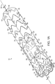
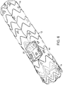
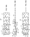
- aortic graft assembly 10 includes tubular aortic component 12 having proximal end 14 and distal end 16 connected by wall 18.
- Wall 18 defines wall aperture 20 that is between proximal end 14 and distal end 16.
- Wall aperture 20 has proximal end 22 that extends perpendicular to a major longitudinal axis 24 of tubular aortic component 12 when viewed orthogonally to major longitudinal axis 24.
- Wall aperture 20 also defines distal end 26 of wall aperture 20.
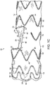
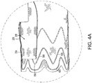
- Tunnel graft 28 shown, for example, in FIGs. 2A, 2B , 3A, 3B , 4A and 4B is connected to wall 18 of tubular aortic component 12 and extends from wall aperture 20 toward proximal end 14 of the tubular aortic component 12.
- Tunnel graft 28 includes proximal end 30 and distal end 32. Distal end 32 of tunnel graft 28 is at wall aperture 20 of tubular aortic component 12.
- proximal stent 34 supports proximal end 14 of tubular aortic component 12.
- Distal stent 36 supports distal end 16 of tubular aortic component 12.
- distal stent 36 can be attached to an interior wall to tubular aortic component 12.
- radiopaque markers 38 are located along a line parallel to major longitudinal axis 24 of tubular aortic component 12.
- radiopaque marker 38 is at a proximal apex of wall aperture distal stent 50 abutting wall aperture 20.
- Another radiopaque marker is at a distal apex 48 of proximal stent 34.
- radiopaque marker 38 is at least one of proximal end 14 and distal end 16 of tubular aortic component 12.
- radiopaque markers 40 extend about the circumference of wall aperture 20 at tubular aortic component 12.
- Radiopaque markers 38, 40 can be made of any suitable material such as platinum, iridium, gold, etc. Examples of radiopaque markers are described in the U.S. Patent No.: 8,062,345 and U.S. Published Patent Application No.: US 201070030255 .
- Wall aperture distal stent 50 includes proximal apices 52 and distal apices 54, a portion of proximal apices 52 of wall aperture distal stent 50 abut distal end 26 of wall aperture 20.
- Clasping stent 56 at proximal end 14 of tubular aortic component 12 includes at least two exposed proximal apices 58 proximate to proximate end 14 of tubular aortic component 12. In one embodiment, clasping stent 56 is attached to an interior wall of tubular aortic component 12.
- Crown stent 60 is located between clasping stent 56 and proximal end 14 of tubular aortic component 12. As can be seen in FIG. 5 , at least two support wire sutures 62 are located within tubular aortic component 12 at proximal end 14 of tubular aortic component 12, distal to proximal apices 58 of clasping stent 56. Support wires sutures 62 are separated by at least one distal apex 61 of clasping stent 56. In one embodiment, proximal apices 59 of crown stent 60 are blunted, as shown in FIG. 1A . Crown stent 60 and clasping stent 56 can be nested, as shown in FIG. 1A . Crown stent 60 and clasping stent 56 are attached to interior wall 76 of tubular aortic component 12.
- At least one stent 64 is located at tubular aortic component 12 between proximal stent 34 and distal stent 36. At least a portion of stents 64 include proximal apices 66 and distal apices 68 connected by struts 70. At least one partial stent 72 is located at tubular aortic component 12 between stents 34, 50 abutting proximal 22 and distal 26 ends of wall aperture 20, respectively, as shown in FIGs. 1B and 1C .
- Stents employed in the invention are constructed of a suitable material.
- the stents employed by the invention include a suitable shape memory alloy, such as nitinol. Further description of suitable materials for construction of stents for use in the invention can be found in U.S. Patent Nos.: 7,763,063 and 8,062,345 .
- the arc length of proximal end 22 of wall aperture 20 is equal to or less than one-half the circumference of tubular aortic component 12.
- suitable arc lengths of proximal end 22 of wall aperture 20 include arc lengths equal to one member selected from the group consisting of about 6 mm, about 8 mm, about 10 mm, about 12 mm or about 14 mm.
- a longitudinal length of wall aperture 20 is equal to or less than about 90 mm. In another embodiment, the longitudinal length of wall aperture 20 is equal to or greater than about 14 mm.
- the distance between proximal end 22 of wall aperture 20 and proximal end 14 of tubular aortic component 12 can be in a range of between about 10 mm and about 80 mm.
- the distance between proximal end 22 of wall aperture 20 and proximal end 14 of tubular aortic component 12 is one member selected from the group consisting of about 20 mm, about 40 mm, about 60 mm, about 80 mm or about 90 mm.
- the distance between proximal end 22 of wall aperture 20 and proximal end 12 of tubular aortic component 12 is about 40 mm, as shown in FIGs. 2A and 2B .
- the distance between proximal end 22 of wall aperture 20 and proximal end 14 of tubular aortic component 12 is about 60 mm, as shown in FIGs. 3A and 3B .
- retention component 78 is located at tubular aortic component 12 distal to wall aperture 20 and within tubular aortic component 12 (only external portion of retention component 78 is shown in FIG. 1A ).
- retention component is a suture loop.
- retention component 78 is at least one of a magnet or a stent apex.
- retention component 78 is radiopaque.
- retention component 78 is at a proximal apex 52 of stent 50 abutting distal end 26 of wall aperture 20.
- circumferential stent 80 is located at tubular aortic component 12 and surrounds wall aperture 20.
- a circumferential stent 80 surrounding wall aperture 20 defines, at least in part, wall aperture 20.
- the diameter of proximal end 14 of tubular aortic component 12 is greater than the diameter of distal end 16 of tubular aortic component 12, as shown in FIG. 1B .
- the interface between tubular aortic component 12 and wall aperture 20, when viewed orthogonally to major longitudinal axis 24 of tubular aortic component 12 is a polygon, such as is shown in the referenced figures, a polygon having four sides.
- the polygon can be a square, a rectangle, a parallelogram, or a rhombus (not shown).
- inferior portion 83 is on one side of tubular aortic component 12 opposite wall aperture 20 and is essentially parallel to major longitudinal axis 24 of tubular aortic component 12, shown in FIG. 1B .
- Exposed apices 58 of clasping stent 56 when collapsed will cause at least partial collapse of proximal end 14 of tubular aortic component 12 at clasping stent 56, as can be seen in FIG. 11 .
- At least one of support wire sutures 62 are at inferior portion 83 within tubular aortic component 12.
- support wire sutures 62 are at apices of clasping stent 56.
- support wire sutures 62 are separated by at least one proximal apex of clasping stent.
- distal end 32 of tunnel graft 28 has a diameter greater than that of proximal end 30 of tunnel graft 28, as can be seen in FIGs. 2A and 3A .
- proximal end 30 of tunnel graft 28 is between the most proximal edge of proximal end 14 of tubular aortic component 12 and proximal end 22 of wall aperture 20, as shown in FIGs. 2A, 2B , 3A, 3B , 4A and 4B .
- tunnel graft 28 is secured to an interior wall of tubular aortic component 12 by a suitable means, such as by sutures 29.
- tunnel graft 28 includes open portion 84 at wall aperture 20.
- Tubular portion 86 extends proximally from open portion 84, as shown in FIGs. 2A, 2B , 3A and 3B .
- tubular portion includes stents 88, 90 at each of a proximal 92 and distal end 94 of tubular portion 86, as shown in FIGs. 2B and 3B .
- stents 88, 90 at proximal 92 and distal 94 ends of tubular portion 86 includes proximal and distal apices connected by struts.
- stent 88 at proximal end 92 of tubular portion 86 includes at least one barb 96 ( FIG. 2B ).
- barbs 96 extend for distal apices of stent 98 of tubular portion 86.
- tubular portion 86 further includes at least one stent 98 between stents 88, 90 at proximal 92 and distal 94 ends, respectively, of tubular portion 86.
- at least one of stents 98 between stents 88, 90 at proximal end 92 and distal end 94 includes at least one barb.
- stents of tubular portion 86 include nitinol.
- distal end 94 of tubular portion 86 is generally conical, whereby distal end 94 of tubular portion 86 essentially matches proximal end 92 of tunnel graft 28 at proximal end 22 of wall aperture 20, as a continuum or, optionally, at a seam, not shown.
- a maximum diameter of proximal end of tunnel graft 28 is equal to or less than the diameter of distal end of tubular portion 94.
- Suitable maximum diameters of proximal end 30 of tunnel graft 28 include, for example, diameters equal to or greater than a diameter selected from the group consisting of about 6 mm, about 8 mm, about 10 mm, about 12 mm or about 14 mm.
- tubular portion 86 has a major longitudinal axis that is parallel to major longitudinal axis 24 of tubular aortic component 12.
- Proximal end 92 of tubular portion 86 is distal to the most proximal edge of proximal end 14 of tubular aortic component 12.
- proximal end 92 of tubular portion 86 is coterminous with the most proximal edge of proximal end 14 of tubular aortic component 12 or, alternatively, as shown in FIGs. 2A and 2B and 3A and 3B , 4A and 4B , is distal to proximal end 14 of tubular aortic component 12.
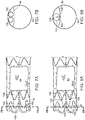
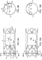
- tubular portion 86 has a major axis at an angle A 81 relative to major longitudinal axis 24 of tubular aortic component 12, as shown in FIG. 9A .
- the angle is in the range of at least one of between about 0° and about 90°, such as 10°, 20°, 30°, 45°, 60°, and 90° C.
- proximal end 92 of tubular portion 86 has geometric center 150 that is distinct from a geometric center 152 of tubular aortic component 12, wherein line 154 defined by geometric center 150 of proximal end 92 of tubular portion 86 and geometric center 152 of tubular aortic component 12 in a plane defined by proximal end 92 of tubular portion 86, taken along line 9 B of FIG. 9A , is at a positive angle B from line 156 defined by geometric center 152 of tubular aortic component 12 and point 158 along centerline 160 bisecting wall aperture 20 and parallel to major longitudinal axis 24 ( FIG.
- suitable positive angles B can be at least one member selected for the group consisting of ⁇ 10°, ⁇ 20°, ⁇ 30°, ⁇ 45°, ⁇ 60°, ⁇ 90°, ⁇ 120°, ⁇ 135°, ⁇ 160°, ⁇ 170° and 180°.
- At least one radiopaque marker 99 is located at at least one of proximal end 92 of tunnel graft 28 and distal end 94 of tubular portion 86 of tunnel graft 28, as shown in FIGs. 2B , 3B and 4B .
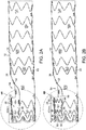
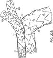
- An embodiment according to the invention includes tubular portion 100 and further includes second tubular portion 102 of tunnel graft 28 extending proximal to open portion 84 of the tunnel graft 28, wherein second tubular portion 102 has distal end 104 and proximal end 106 as shown in FIGs. 7A, 7B, 8A and 8B .
- second tubular portion 102 is of unequal length to that of first tubular portion 100.
- second tubular portion 102 is parallel to first tubular portion 100.
- First tubular portion 100 and second tubular portion 102 are each a distinct, and integrally complete tubular portion.
- tubular portions share common wall of a first graft material 108 that partition a conduit of the second graft material 110.
- first 108 and second 110 graft materials define, at least in part, first tubular portion 100 and second tubular portion 102.
- tubular portions 112 and 114 extend away from each other and proximally from open portion 84.
- proximal end 92 of tunnel graft 28 has a diameter in a range between about 5 mm and about 10 mm, or between about 5 mm and about 15 mm, or between about 8 mm and about 15 mm.
- tubular portion 86 has a length in a range of between about 20 mm and about 60 mm, or between about 20 mm and about 100 mm. Most commonly, tubular portion 86 has a length in a range between about 30 and 50 mm.
- proximal end 92 of tunnel graft 28 is within at least about 5 mm, about 10 mm, and about 15 mm or about 20 mm of proximal end 14 of tubular aortic component 12.
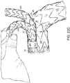
- FIG. 12 shows one embodiment of aortic graft assembly 10 of the invention fully deployed within aorta 117 of a patient.
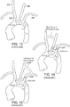
- FIGs. 13-15 show various stages of an aortic bypass operation (prior art).
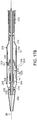
- aortic graft assembly 200 ( FIG. 16A ) includes delivery component 202 ( FIG. 16B ) to which tubular aortic component 12 ( FIG. 16A ) is attached ( FIGs. 16A and 16C ).
- Delivery component 202 includes control catheter 204 ( FIG. 16B ), about which tubular aortic component 12 ( FIG. 16C ) extends, nose cone 206 ( FIGs. 16B and 16C ) is fixed at a distal end of control catheter 204 ( FIGs. 17A and 17B ).
- delivery component 202 further includes inner sheath 210 extending about control catheter 204.
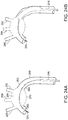
- a distal opening at distal end 214 of inner sheath 210, can be tucked into nose cone 206 ( FIGs. 17A , 17B and 18 ).
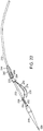
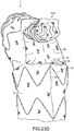
- inner sheath 210 includes inferior portion 82, said inferior portion 82 having fluted portion 85 as can be seen in FIG. 20 .
- inner sheath 210 can be tapered to narrow toward distal end 211 or of essentially constant diameter.
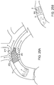
- inner sheath 210 defines at least one through hole 280 at proximal end 282 of inner sheath 210, as shown in FIGs. 25A and 25B .
- introducer sheath 216 extends about inner sheath 210 and about tubular aortic component 12, wherein introducer sheath 216 is retractable relative to inner sheath 210 to thereby release distal end 214 of inner sheath 210. Nose cone 206 can thereafter be retracted within inner sheath 210.
- Delivery component 202 further includes at least one supporting wire 230 fixed at proximal end 224 to support base 235, substantially parallel to a major longitudinal axis of outer control tube 232 and free at the distal end 228, wherein free end 228 of at least one of supporting wire 230 and internal sutures 62 ( FIG. 17B ) at the proximal end 14 of tubular aortic component 12 releasably secures proximal end 14 of tubular aortic component 12 to at least one of supporting wires 230.
- Outer control tube 232 is slidable along control catheter 204.
- Supporting wires 230 are fixed at proximal ends 224 to support base 235 at outer control tube 232 distal to proximal apex clasp 240. Free ends 228 of support wires 230 are proximate to proximal end 14 and to nose cone 206. Proximal portion 252 of distal apex clasp 238 and outer control tube 232 are slidable along the control catheter 204 with movement of outer control tube 232 ( FIGs. 16B and 22 ). Distal apex clasp 238 fixes proximal end 14 of tubular aortic component 12 by securing exposed apices 58 ( FIG. 16C ) of clasping stent 56 at proximal end 14 of tubular aortic component 12.
- distal portion 248 of distal apex clasp 238 mates with of teeth 252 of proximal portion 250 of distal apex clasp 238 in a closed position that secures exposed apices 58 of clasping stent 56 of tubular aortic component 12.
- Proximal apex clasp 240 is at outer control tube 232 ( FIG. 17B ).
- Proximal apex clasp 240 includes teeth 246 ( FIG. 16B ) extending distally from proximal portion 244 of proximal clasp 240.
- Teeth 246 extend distally through retention component 78 of tubular aortic component 12, as shown in FIG. 17B .
- tubular branch component 254 includes proximal end 256 and distal end 258, wherein proximal end 256 of tubular branch component 254 is configured to engage proximal end 30 of tunnel graft 28. In an embodiment, the engagement is by interfering relation between tubular branch component 254 and tunnel graft 28.
- a seal forms with at least one member of the group consisting of the proximal end of at least one of the tubular aortic component 12, tubular branch component 254 and second tubular branch component 260, and the distal end of at least one of tubular aortic component 12, tubular branch component 254 and second tubular component 260.
- a "seal" as defined herein, means that essentially no fluid will seep between the wall of a first conduit and the wall of a second conduit within which the first conduit is located. Such seals typically will be at the most proximal portion of a juncture between nested first and second conduits.
- supporting wire 230 has at least one stop 274 ( FIG. 11 ), wherein stop 274 limits movement of suture loop 62 along supporting wire 230.
- tubular aortic component 12 includes radiopaque sutures 18 and inner sheath 210 includes radiopaque markers 276, all of which are longitudinally aligned along a path of relative movement of inner sheath 210 ( FIGs. 16A-16F and 17A-17C ) and tubular aortic component 12 during deployment of tubular aortic component 12, and are spaced apart from each other, whereby partial retraction of inner sheath 210 will cause overlap of radiopaque markers 276 with radiopaque markers 38.
- radiopaque markers 38 are also, or alternatively, on superior portions of inner sheath 210 and tubular aortic component 12.
- radiopaque markers 38, 276 are asymmetric, wherein a shape of radiopaque markers 38, 276 changes as radiopaque markers 38, 276 are aligned with a surgical site.
- radiopaque markers 38, 276 of tubular aortic component 12 are elongated and are substantially aligned with the major longitudinal axis 24 of inner sheath 210.
- tubular aortic component 12 is further constrained at at least one end by a clasp, such as distal apex clasp 238 or proximal apex clasp 240, and the method includes the step of releasing the clasp with retraction of supporting wire 230 from suture loop 62 of tubular aortic component 12.
- tubular aortic component 12 further includes at least one radiopaque marker 38, wherein, preferably, radiopaque marker 38 is located on tubular aortic component 12 facing away from cavity 284 ( FIG. 18 ) of the curve 286 ( FIG. 18 ) defined by control catheter 204.
- inner sheath 210 further includes at least one radiopaque marker 276, wherein radiopaque marker 276 of inner sheath 210 overlaps at least one radiopaque marker 276 of tubular aortic component 12 when tubular aortic component 12 is partially deployed.
- tubular aortic component 12 is further constrained by proximal clasp 240 and proximal fixed end 234 of supporting wire 230.
- a method for implanting a prosthesis of the invention includes the steps of delivering tubular aortic component 12 within introducer sheath 216 along guidewire 320 through an aorta 262 to aneurysm 270 of the patient, shown in FIGs. 24A-24E .
- Tubular aortic component 12 is radially constrained and supported at least in part by control catheter 204 ( FIGs. 16B, 16C , 16D ), which is slidable along guidewire 320 ( FIGs. 24A-24E ). As shown in FIGs.
- tubular aortic component 12 is further longitudinally constrained by at least one supporting wire 230 extending from support base 235 at outer control tube 232 extending about and slidable along control catheter 204.
- Free end 228 of at least one of supporting wire 230 is arcuate and extends through suture loop 62 ( FIG. 17B ), within proximal end 14 of tubular aortic component 12.
- tubular aortic component 12 is guided to aneurysm 270 along guidewire 320.
- Inner sheath 210 ( FIG. 17B ), is partially retracted from tubular aortic component 12, whereby supporting wire 230 at least partially restricts longitudinal movement of proximal end 14 of tubular aortic component 12 until proximal end 14 of tubular aortic component 12 is secure within aorta 262 ( FIGs. 24A-24E ) of the patient to thereby prevent collapse of proximal end 14 of tubular aortic component 12 at an inferior portion 264 of aorta 262.
- inner sheath 210 is releasably secured at distal end 214 within a cavity defined by the proximal end of nose cone 206 ( FIG. 18 ).
- optional inner sheath 210 is partially retracted to release the distal end of the inner sheath 210 from nose cone 206 and thereby cause partial expansion of tubular aortic component 12.
- Wall aperture 20 is aligned over at least one vessel ostium 290, 292, 294 at aneurysm site 263 of the patient.
- inner sheath 210 is then partially retracted to expose the proximal end 14 of tubular aortic component 12, including crown stent 56 and the clasping stent 60 ( FIG. 1A ).
- Control tube 232 is then partially extended to release bare apices 58 ( FIG. 1A ) of clasping stent 56 from distal clasp 238 and to release retention component 78 from proximal clasp 240 ( FIGs. 16B and 17B ), while retaining suture loops 62 on ends 228 of support wires 230 ( FIGs. 16A-16F and 17A-17C ).
- Nose cone 206 is then partially retracted into proximal end of tubular aortic component 12 and the delivery assembly and tubular aortic component 12 are then advanced to a final position within aorta 262 spanning aneurysm 263 of the patient.
- Control tube 232 is then further retracted to release suture loops 62 from ends 228 of support wires 230.
- Inner sheath 210 is then fully retracted (in embodiments of the invention that employ inner sheath 210) and then nose cone 206 and supporting wires 230 are fully retracted to complete deployment of tubular aortic component 12.
- the method of the invention includes the step of implanting at least one tubular branch component 254 in at least one of an innominate artery (also referred to as "brachiocephalic artery") 290, a left subclavian artery 292, a left common carotid artery 294, or right common carotid artery 296 of the patient into wall aperture 20 and tunnel graft 28 within tubular aortic component 12, as shown, with respect to the prior art, in FIGs. 13-15 , and in FIGs. 24A-24E .
- the method of the invention includes the steps of implanting tubular branch component 254 into innominate artery 290, and another tubular branch component, into the left common carotid artery 294 ( FIG. 24E ).
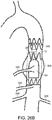
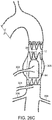
- Implantation of the aortic graft assemblies of the invention can include implantation in at least one of a portion of the ascending aorta, the aortic arch, the descending aorta and abdominal aorta (see FIGs. 12 , 24A-24E and 26A-26C ). Implantation near, around or at the arch of the aorta, can include a right common carotid to left common carotid artery bypass with ligation of the left common carotid inferior to the point of the bypass and a left common carotid artery to left subclavian artery bypass with ligation inferior to the bypass.
- an aortic graft assembly of the invention that includes two tubular branch components (e.g., one into the right common carotid, another into the left common carotid) can include a left common carotid artery to left subclavian artery bypass, with ligation of the left subclavian artery inferior to the bypass (see FIGs. 16 and 17 ).
- aortic assembly systems can be implanted in the abdominal aorta 300. Opening 84 can be placed in abdominal aorta proximate to celiac artery 302, superior mesenteric artery 304 or renal artery 306, thereby spanning aneurysm 308.
- Tubular branch component 254 can then be implanted into at least one of celiac artery 302, superior mesenteric artery 304 or at least one renal artery 306.
- inner sheath 210 about tubular aortic component 12 includes proximal perforated portion 280 that defines through-holes 282.
- Through-holes 282 can be defined by a mesh or fabric of perforation portion 280, as shown in FIG. 25A , or as distinct openings, such as longitudinal through-hole opening 284 shown in FIG. 25B .
- the through-holes permit relatively continuous blood flow during implantation of the prosthesis, as further described in U.S. Published Patent Application No.: 2010/0234932 .
- Patent Nos.: 7,763,063 ; 8,007,605 ; 8,062,345 ; 8,062,349 ; 8,070,790 ; 8,292,943 and 8,308,790 can be employed to deliver the aortic graft assembly of the invention.
- a 74 year old male with penetrating atherosclerotic ulcer (PAU) of the aorta located on the interior side of the thoracic arch at the level of the left common carotid was treated.
- a model of the patient's anatomy was made based on computer tomography (CT) scanning.
- a right carotid to left carotid bypass was performed initially without ligating the left carotid.
- a tubular aortic component of an aortic graft assembly (46 mm-42 mm x 80 mm) was deployed at the sinotubular junction.
- the ascending aorta of this patent had a graft diameter of about 44 mm.
- a tubular aortic component having a diameter of 46/42 mm x 80 mm was employed to provide a smaller healthy neck.
- the proximal end of the tubular aortic component of the aortic graft assembly was released to optimize apposition with the wall of the ascending aorta.
- a tunnel graft (46 mm-34 mm x 220 mm) was used in the aortic graft assembly.
- the tunnel graft was 15 mm in diameter.
- the aperture of the tubular aortic component was 30 mm x 30 mm.
- a graft of a size of 15 mm - 17 mm x 100 mm or 15 mm - 17 mm x 110 mm) was employed to bridge the graft tunnel with the brachial cephalic trunk and a wire-catheter was positioned prior to implantation as a precautionary bailout.
- An angiogram was performed to confirm profusion to the and left common carotid arteries.
- the tunnel graft was advanced to the proximal portion of the aperture of the tubular aortic component with the distal end of at least one tubular branch component.
- the graft was aligned to allow canulation of the tunnel graft through the innominate or the left common carotid arteries based on movement of the tubular aortic component.
- the tunnel graft was canulated via the right common carotid.
- a relatively short tubular branch component was selected in this patient because the tunnel graft was deployed more distally.
- the distal end of the branch graft was aligned with the brachial cephalic trunk bifurcation and the tubular branch graft deployed without complication.
- An angiogram showed exclusion of the aneurysm with flow to the innominate artery and left common carotid artery via a carotid-carotid bypass.
- An 81 year old male with an aneurysm at the arch of the aorta was treated.
- a CT scan was employed to model the patient's anatomy.
- the thoracic aneurysm was in a region of the aortic arch and at least a portion of the descending aorta.
- the tunnel graft had a diameter of about 15 mm.
Landscapes
- Health & Medical Sciences (AREA)
- Engineering & Computer Science (AREA)
- Biomedical Technology (AREA)
- Heart & Thoracic Surgery (AREA)
- Public Health (AREA)
- Transplantation (AREA)
- Cardiology (AREA)
- Veterinary Medicine (AREA)
- Oral & Maxillofacial Surgery (AREA)
- Vascular Medicine (AREA)
- Life Sciences & Earth Sciences (AREA)
- Animal Behavior & Ethology (AREA)
- General Health & Medical Sciences (AREA)
- Gastroenterology & Hepatology (AREA)
- Pulmonology (AREA)
- Prostheses (AREA)
- Media Introduction/Drainage Providing Device (AREA)
Applications Claiming Priority (3)
| Application Number | Priority Date | Filing Date | Title |
|---|---|---|---|
| US201161560517P | 2011-11-16 | 2011-11-16 | |
| PCT/US2012/065622 WO2013074990A1 (en) | 2011-11-16 | 2012-11-16 | Device and method for aortic branched vessel repair |
| EP12805487.1A EP2779940B3 (en) | 2011-11-16 | 2012-11-16 | Device for aortic branched vessel repair |
Related Parent Applications (2)
| Application Number | Title | Priority Date | Filing Date |
|---|---|---|---|
| EP12805487.1A Division EP2779940B3 (en) | 2011-11-16 | 2012-11-16 | Device for aortic branched vessel repair |
| EP12805487.1A Division-Into EP2779940B3 (en) | 2011-11-16 | 2012-11-16 | Device for aortic branched vessel repair |
Publications (2)
| Publication Number | Publication Date |
|---|---|
| EP3272312A1 EP3272312A1 (en) | 2018-01-24 |
| EP3272312B1 true EP3272312B1 (en) | 2019-05-22 |
Family
ID=47425286
Family Applications (2)
| Application Number | Title | Priority Date | Filing Date |
|---|---|---|---|
| EP12805487.1A Active EP2779940B3 (en) | 2011-11-16 | 2012-11-16 | Device for aortic branched vessel repair |
| EP17159404.7A Active EP3272312B1 (en) | 2011-11-16 | 2012-11-16 | Device for aortic branched vessel repair |
Family Applications Before (1)
| Application Number | Title | Priority Date | Filing Date |
|---|---|---|---|
| EP12805487.1A Active EP2779940B3 (en) | 2011-11-16 | 2012-11-16 | Device for aortic branched vessel repair |
Country Status (7)
| Country | Link |
|---|---|
| US (4) | US9592112B2 (ja) |
| EP (2) | EP2779940B3 (ja) |
| JP (2) | JP6097303B2 (ja) |
| CN (2) | CN104066401B (ja) |
| BR (1) | BR112014011779A2 (ja) |
| ES (2) | ES2740804T3 (ja) |
| WO (1) | WO2013074990A1 (ja) |
Families Citing this family (72)
| Publication number | Priority date | Publication date | Assignee | Title |
|---|---|---|---|---|
| US9198786B2 (en) | 2003-09-03 | 2015-12-01 | Bolton Medical, Inc. | Lumen repair device with capture structure |
| US8500792B2 (en) | 2003-09-03 | 2013-08-06 | Bolton Medical, Inc. | Dual capture device for stent graft delivery system and method for capturing a stent graft |
| US7763063B2 (en) | 2003-09-03 | 2010-07-27 | Bolton Medical, Inc. | Self-aligning stent graft delivery system, kit, and method |
| US20070198078A1 (en) | 2003-09-03 | 2007-08-23 | Bolton Medical, Inc. | Delivery system and method for self-centering a Proximal end of a stent graft |
| US20080264102A1 (en) | 2004-02-23 | 2008-10-30 | Bolton Medical, Inc. | Sheath Capture Device for Stent Graft Delivery System and Method for Operating Same |
| US8292943B2 (en) | 2003-09-03 | 2012-10-23 | Bolton Medical, Inc. | Stent graft with longitudinal support member |
| US11259945B2 (en) | 2003-09-03 | 2022-03-01 | Bolton Medical, Inc. | Dual capture device for stent graft delivery system and method for capturing a stent graft |
| US11596537B2 (en) | 2003-09-03 | 2023-03-07 | Bolton Medical, Inc. | Delivery system and method for self-centering a proximal end of a stent graft |
| EP3219292B1 (en) | 2008-06-30 | 2019-08-14 | Bolton Medical Inc. | Abdominal aortic aneurysms systems |
| CN102413794B (zh) | 2009-03-13 | 2017-02-08 | 波顿医疗公司 | 用于在手术部位部署腔内假体的系统和方法 |
| US9839540B2 (en) | 2011-01-14 | 2017-12-12 | W. L. Gore & Associates, Inc. | Stent |
| ES2675177T3 (es) | 2011-11-11 | 2018-07-09 | Bolton Medical, Inc. | Injertos endovasculares universales |
| CN104066401B (zh) | 2011-11-16 | 2016-11-09 | 波顿医疗公司 | 用于主动脉分支血管的修复的装置和方法 |
| CN104363862B (zh) | 2012-04-12 | 2016-10-05 | 波顿医疗公司 | 血管假体输送装置及使用方法 |
| US9283072B2 (en) | 2012-07-25 | 2016-03-15 | W. L. Gore & Associates, Inc. | Everting transcatheter valve and methods |
| US9066793B2 (en) * | 2012-11-12 | 2015-06-30 | Yen-Ni Hung | Method of implanting an aortic stent |
| US9931193B2 (en) | 2012-11-13 | 2018-04-03 | W. L. Gore & Associates, Inc. | Elastic stent graft |
| US9144492B2 (en) | 2012-12-19 | 2015-09-29 | W. L. Gore & Associates, Inc. | Truncated leaflet for prosthetic heart valves, preformed valve |
| US9968443B2 (en) | 2012-12-19 | 2018-05-15 | W. L. Gore & Associates, Inc. | Vertical coaptation zone in a planar portion of prosthetic heart valve leaflet |
| US9101469B2 (en) | 2012-12-19 | 2015-08-11 | W. L. Gore & Associates, Inc. | Prosthetic heart valve with leaflet shelving |
| US9993330B2 (en) * | 2013-03-13 | 2018-06-12 | Cook Medical Technologies Llc | Endoluminal prosthesis system |
| US9439751B2 (en) | 2013-03-15 | 2016-09-13 | Bolton Medical, Inc. | Hemostasis valve and delivery systems |
| US10842918B2 (en) | 2013-12-05 | 2020-11-24 | W.L. Gore & Associates, Inc. | Length extensible implantable device and methods for making such devices |
| US9827094B2 (en) | 2014-09-15 | 2017-11-28 | W. L. Gore & Associates, Inc. | Prosthetic heart valve with retention elements |
| US10524893B2 (en) | 2014-09-23 | 2020-01-07 | Bolton Medical, Inc. | Vascular repair devices and methods of use |
| CN107106310B (zh) * | 2014-10-22 | 2019-03-22 | 波士顿科学国际有限公司 | 具有柔性铰链的支架 |
| JP7007294B2 (ja) | 2016-04-05 | 2022-01-24 | ボルトン メディカル インコーポレイテッド | 内部トンネルおよび開窓を有するステントグラフト |
| ES2956016T3 (es) | 2016-04-21 | 2023-12-11 | Gore & Ass | Endoprótesis ajustables diametralmente |
| WO2017205486A1 (en) | 2016-05-25 | 2017-11-30 | Bolton Medical, Inc. | Stent grafts and methods of use for treating aneurysms |
| US20180206972A1 (en) | 2016-08-10 | 2018-07-26 | Bolton Medical, Inc. | Graft prosthesis coupler, modular system, and methods of use |
| WO2018049111A1 (en) | 2016-09-09 | 2018-03-15 | W. L. Gore & Associates, Inc. | Total arch concept |
| US10537419B2 (en) * | 2016-10-27 | 2020-01-21 | Cook Medical Technologies Llc | Prosthesis with branched portion |
| WO2018156848A1 (en) | 2017-02-24 | 2018-08-30 | Bolton Medical, Inc. | Vascular prosthesis with crimped adapter and methods of use |
| WO2018156853A1 (en) | 2017-02-24 | 2018-08-30 | Bolton Medical, Inc. | Delivery system for radially constricting a stent graft and method of use |
| WO2018156851A1 (en) | 2017-02-24 | 2018-08-30 | Bolton Medical, Inc. | Vascular prosthesis with moveable fenestration |
| CN109890331B (zh) * | 2017-02-24 | 2022-07-12 | 波顿医疗公司 | 具有收缩护套的支架移植物递送系统和使用方法 |
| JP7479844B2 (ja) | 2017-02-24 | 2024-05-09 | ボルトン メディカル インコーポレイテッド | 束縛可能なステントグラフト、送達システムおよび使用方法 |
| WO2018156854A1 (en) | 2017-02-24 | 2018-08-30 | Bolton Medical, Inc. | Radially adjustable stent graft delivery system |
| WO2018156850A1 (en) | 2017-02-24 | 2018-08-30 | Bolton Medical, Inc. | Stent graft with fenestration lock |
| WO2018156849A1 (en) | 2017-02-24 | 2018-08-30 | Bolton Medical, Inc. | Vascular prosthesis with fenestration ring and methods of use |
| ES2863978T3 (es) | 2017-02-24 | 2021-10-13 | Bolton Medical Inc | Sistema para constreñir radialmente un injerto de stent |
| WO2018156847A1 (en) | 2017-02-24 | 2018-08-30 | Bolton Medical, Inc. | Delivery system and method to radially constrict a stent graft |
| JP7275097B2 (ja) | 2017-07-07 | 2023-05-17 | エンドーロジックス リミテッド ライアビリティ カンパニー | 主動脈及び動脈枝において展開するための血管内グラフトシステム及び方法 |
| DE102017120819A1 (de) * | 2017-09-08 | 2019-03-14 | Jotec Gmbh | Intraluminales Gefäßprothesensystem |
| JP7068444B2 (ja) | 2017-09-27 | 2022-05-16 | ダブリュ.エル.ゴア アンド アソシエイツ,インコーポレイティド | 拡張可能なフレームを備えた人工弁、並びに関連するシステム及び方法 |
| CA3155761A1 (en) | 2017-09-27 | 2019-04-04 | W.L. Gore & Associates, Inc. | Prosthetic valves with mechanically coupled leaflets |
| CA3078496C (en) * | 2017-10-09 | 2023-02-28 | W. L. Gore & Associates, Inc. | Matched stent cover |
| WO2019078346A1 (ja) * | 2017-10-20 | 2019-04-25 | 川澄化学工業株式会社 | 管状治療具、管状治療具セット及び管状治療具留置装置 |
| CN111295158A (zh) | 2017-10-31 | 2020-06-16 | W.L.戈尔及同仁股份有限公司 | 医用瓣膜和促进组织向内生长的瓣叶 |
| EP4049633A1 (en) | 2017-10-31 | 2022-08-31 | Bolton Medical, Inc. | Distal torque component, delivery system and method of using same |
| US11648137B2 (en) | 2017-11-24 | 2023-05-16 | Ptmc Institute | Stent graft transport device |
| WO2019103084A1 (ja) * | 2017-11-27 | 2019-05-31 | 川澄化学工業株式会社 | ステントグラフト及びステントグラフト留置装置 |
| CN109984864B (zh) * | 2017-12-29 | 2020-07-17 | 先健科技(深圳)有限公司 | 用于分支血管的支架 |
| CN112118807A (zh) | 2018-06-19 | 2020-12-22 | 美敦力瓦斯科尔勒公司 | 用于多个血管的模块化支架装置和方法 |
| CN109009563B (zh) * | 2018-08-27 | 2024-01-23 | 复旦大学附属中山医院 | 一种改进的主动脉弓覆膜支架型血管 |
| FR3087113B1 (fr) * | 2018-10-12 | 2022-04-08 | Ludovic Canaud | Implant aortique de type stent, et ensemble forme de deux tels implants |
| EP3917461A2 (en) | 2019-02-01 | 2021-12-08 | Bolton Medical, Inc. | Expandable luminal stents and methods of use |
| US11497601B2 (en) | 2019-03-01 | 2022-11-15 | W. L. Gore & Associates, Inc. | Telescoping prosthetic valve with retention element |
| AU2020242051A1 (en) | 2019-03-20 | 2021-11-04 | inQB8 Medical Technologies, LLC | Aortic dissection implant |
| US11116650B2 (en) | 2019-03-28 | 2021-09-14 | Medtronic Vascular, Inc. | Supra aortic access modular stent assembly and method |
| US11083605B2 (en) | 2019-03-28 | 2021-08-10 | Medtronic Vascular, Inc. | Femoral aortic access modular stent assembly and method |
| EP3976124A4 (en) * | 2019-05-31 | 2023-02-08 | DOSE Medical Corporation | CROSS-LINKED HYDROGEL BIOERODABLE IMPLANTS AND ASSOCIATED METHODS OF USE |
| US11096775B2 (en) | 2019-07-03 | 2021-08-24 | Medtronic Vascular, Inc. | Single multibranch stent device assembly and method |
| US11826226B2 (en) | 2019-07-31 | 2023-11-28 | Medtronic Vascular, Inc. | Modular multibranch stent assembly and method |
| US11191633B2 (en) | 2019-08-29 | 2021-12-07 | Medtronic Vascular, Inc. | Modular multibranch stent assembly and method |
| US11324582B2 (en) | 2019-09-27 | 2022-05-10 | Medtronic Vascular, Inc. | Docking graft for placement of parallel distally extending grafts assembly and method |
| AU2021286653A1 (en) * | 2020-06-10 | 2023-01-19 | W. L. Gore & Associates, Inc. | Multi-branch intraluminal devices and methods of making and using same |
| JP2023548040A (ja) | 2020-11-09 | 2023-11-15 | ボルトン メディカル インコーポレイテッド | 大動脈プロテーゼ送達システムおよび使用方法 |
| EP4337144A1 (en) | 2021-05-11 | 2024-03-20 | Bolton Medical, Inc. | Aortic prosthesis delivery device and method of use |
| CN117813067A (zh) | 2021-07-26 | 2024-04-02 | 波顿医疗公司 | 具有通道移植物和栓塞过滤器的主动脉假体 |
| WO2023114371A2 (en) | 2021-12-16 | 2023-06-22 | Bolton Medical, Inc. | Stent graft crimping device and method of use |
| GB2623515A (en) * | 2022-10-17 | 2024-04-24 | Cook Medical Technologies Llc | Stent graft assembly |
Citations (16)
| Publication number | Priority date | Publication date | Assignee | Title |
|---|---|---|---|---|
| US6540779B2 (en) | 1996-05-03 | 2003-04-01 | Medinol Ltd. | Bifurcated stent with improved side branch aperture and method of making same |
| US6645242B1 (en) | 2000-12-11 | 2003-11-11 | Stephen F. Quinn | Bifurcated side-access intravascular stent graft |
| US20070088424A1 (en) | 2005-09-21 | 2007-04-19 | William A. Cook Australia Pty Ltd. | Endoluminal delivery assembly |
| US7264632B2 (en) | 2002-06-07 | 2007-09-04 | Medtronic Vascular, Inc. | Controlled deployment delivery system |
| US7413573B2 (en) | 2003-10-10 | 2008-08-19 | William A. Cook Australia Pty. Ltd. | Fenestrated stent grafts |
| WO2008130503A2 (en) | 2007-04-24 | 2008-10-30 | Gore Enterprise Holdings, Inc. | Catheter having guidewire channel |
| US20080281399A1 (en) | 2004-06-15 | 2008-11-13 | Williams A. Cook Australia Pty. Ltd. | Stent Graft With Internal Tube |
| US20090043377A1 (en) | 2003-01-14 | 2009-02-12 | The Cleveland Clinic Foundation | Branched Vessel Endoluminal Device |
| WO2009020653A1 (en) | 2007-08-08 | 2009-02-12 | Cleveland Clinic Foundation | Branched stent graft system |
| US20100030318A1 (en) | 2003-09-03 | 2010-02-04 | Bolton Medical, Inc. | Dual Capture Device for Stent Graft Delivery System and Method for Capturing a Stent Graft |
| WO2010024879A1 (en) | 2008-08-26 | 2010-03-04 | William A. Cook Australia Pty. Ltd. | Thoracic aorta stent graft with access region |
| WO2010105195A2 (en) | 2009-03-13 | 2010-09-16 | Bolton Medical, Inc. | System and method for deploying an endoluminal prosthesis at a surgical site |
| US7914572B2 (en) | 2006-02-13 | 2011-03-29 | William A. Cook Australia Pty. Ltd. | Side branch stent graft construction |
| US20110087318A1 (en) | 2009-10-09 | 2011-04-14 | Daugherty John R | Bifurcated highly conformable medical device branch access |
| US7972374B2 (en) | 2007-10-29 | 2011-07-05 | Cleveland Clinic Foundation | Securing rods and modular graft systems |
| WO2011100290A1 (en) | 2010-02-09 | 2011-08-18 | Cook Medical Technologies Llc | Thoracic aorta stent graft |
Family Cites Families (121)
| Publication number | Priority date | Publication date | Assignee | Title |
|---|---|---|---|---|
| US4501263A (en) | 1982-03-31 | 1985-02-26 | Harbuck Stanley C | Method for reducing hypertension of a liver |
| US5190546A (en) | 1983-10-14 | 1993-03-02 | Raychem Corporation | Medical devices incorporating SIM alloy elements |
| US5123917A (en) | 1990-04-27 | 1992-06-23 | Lee Peter Y | Expandable intraluminal vascular graft |
| US5231989A (en) | 1991-02-15 | 1993-08-03 | Raychem Corporation | Steerable cannula |
| US5474563A (en) * | 1993-03-25 | 1995-12-12 | Myler; Richard | Cardiovascular stent and retrieval apparatus |
| US5855598A (en) | 1993-10-21 | 1999-01-05 | Corvita Corporation | Expandable supportive branched endoluminal grafts |
| US5507769A (en) | 1994-10-18 | 1996-04-16 | Stentco, Inc. | Method and apparatus for forming an endoluminal bifurcated graft |
| US5575817A (en) | 1994-08-19 | 1996-11-19 | Martin; Eric C. | Aorto femoral bifurcation graft and method of implantation |
| US5683449A (en) | 1995-02-24 | 1997-11-04 | Marcade; Jean Paul | Modular bifurcated intraluminal grafts and methods for delivering and assembling same |
| US5709713A (en) | 1995-03-31 | 1998-01-20 | Cardiovascular Concepts, Inc. | Radially expansible vascular prosthesis having reversible and other locking structures |
| US5843160A (en) | 1996-04-01 | 1998-12-01 | Rhodes; Valentine J. | Prostheses for aneurysmal and/or occlusive disease at a bifurcation in a vessel, duct, or lumen |
| DE69736676T2 (de) | 1996-11-04 | 2007-01-11 | Advanced Stent Technologies, Inc., Pleasanton | Aufweitbarer doppelstent |
| AUPO700897A0 (en) | 1997-05-26 | 1997-06-19 | William A Cook Australia Pty Ltd | A method and means of deploying a graft |
| US6187033B1 (en) | 1997-09-04 | 2001-02-13 | Meadox Medicals, Inc. | Aortic arch prosthetic graft |
| US6306164B1 (en) | 1997-09-05 | 2001-10-23 | C. R. Bard, Inc. | Short body endoprosthesis |
| US5984955A (en) | 1997-09-11 | 1999-11-16 | Wisselink; Willem | System and method for endoluminal grafting of bifurcated or branched vessels |
| US5910144A (en) | 1998-01-09 | 1999-06-08 | Endovascular Technologies, Inc. | Prosthesis gripping system and method |
| US6395018B1 (en) | 1998-02-09 | 2002-05-28 | Wilfrido R. Castaneda | Endovascular graft and process for bridging a defect in a main vessel near one of more branch vessels |
| US5938697A (en) * | 1998-03-04 | 1999-08-17 | Scimed Life Systems, Inc. | Stent having variable properties |
| US6171334B1 (en) | 1998-06-17 | 2001-01-09 | Advanced Cardiovascular Systems, Inc. | Expandable stent and method of use |
| US6059824A (en) | 1998-12-23 | 2000-05-09 | Taheri; Syde A. | Mated main and collateral stent and method for treatment of arterial disease |
| DE10084521T1 (de) | 1999-05-07 | 2002-06-20 | Salviac Ltd | Embolieschutzgerät |
| US6585756B1 (en) | 1999-05-14 | 2003-07-01 | Ernst P. Strecker | Implantable lumen prosthesis |
| US6344056B1 (en) | 1999-12-29 | 2002-02-05 | Edwards Lifesciences Corp. | Vascular grafts for bridging a vessel side branch |
| US6325823B1 (en) | 1999-10-29 | 2001-12-04 | Revasc Corporation | Endovascular prosthesis accommodating torsional and longitudinal displacements and methods of use |
| US8092511B2 (en) | 2000-03-03 | 2012-01-10 | Endovascular Technologies, Inc. | Modular stent-graft for endovascular repair of aortic arch aneurysms and dissections |
| US6814752B1 (en) | 2000-03-03 | 2004-11-09 | Endovascular Technologies, Inc. | Modular grafting system and method |
| US6773454B2 (en) | 2000-08-02 | 2004-08-10 | Michael H. Wholey | Tapered endovascular stent graft and method of treating abdominal aortic aneurysms and distal iliac aneurysms |
| US6595963B1 (en) | 2000-09-07 | 2003-07-22 | Coaxia, Inc. | Aortic shunt for selective cerebral perfusion in stroke and cardiac arrest |
| WO2002038085A1 (en) | 2000-11-13 | 2002-05-16 | Kensey Kenneth R | Device and method for reducing blood pressure |
| US8870946B1 (en) | 2000-12-11 | 2014-10-28 | W.L. Gore & Associates, Inc. | Method of deploying a bifurcated side-access intravascular stent graft |
| US7014653B2 (en) | 2001-12-20 | 2006-03-21 | Cleveland Clinic Foundation | Furcated endovascular prosthesis |
| US20030130725A1 (en) | 2002-01-08 | 2003-07-10 | Depalma Donald F. | Sealing prosthesis |
| US6723116B2 (en) | 2002-01-14 | 2004-04-20 | Syde A. Taheri | Exclusion of ascending/descending aorta and/or aortic arch aneurysm |
| JP4208075B2 (ja) * | 2002-03-25 | 2009-01-14 | クック インコーポレイティド | 二股の/枝分かれした血管用プロテーゼ |
| US7131991B2 (en) | 2002-04-24 | 2006-11-07 | Medtronic Vascular, Inc. | Endoluminal prosthetic assembly and extension method |
| US6676699B2 (en) | 2002-04-26 | 2004-01-13 | Medtronic Ave, Inc | Stent graft with integrated valve device and method |
| US7550004B2 (en) | 2002-08-20 | 2009-06-23 | Cook Biotech Incorporated | Endoluminal device with extracellular matrix material and methods |
| AU2003262754B2 (en) | 2002-08-23 | 2007-06-21 | Cook Incorporated | Composite prosthesis |
| US7731744B1 (en) * | 2002-10-25 | 2010-06-08 | Advanced Cariovascular Systems, Inc. | Intravascular stent for treating vulnerable plaque and method of use |
| CA2507649C (en) | 2003-04-02 | 2011-10-11 | Mehran Bashiri | Detachable and retrievable stent assembly |
| CA2518890C (en) | 2003-04-03 | 2012-06-05 | William A. Cook Australia Pty. Ltd. | Branch stent graft deployment and method |
| US7438721B2 (en) | 2003-04-25 | 2008-10-21 | Medtronic Vascular, Inc. | Universal modular stent graft assembly to accommodate flow to collateral branches |
| US20040230289A1 (en) | 2003-05-15 | 2004-11-18 | Scimed Life Systems, Inc. | Sealable attachment of endovascular stent to graft |
| US7763063B2 (en) | 2003-09-03 | 2010-07-27 | Bolton Medical, Inc. | Self-aligning stent graft delivery system, kit, and method |
| US9198786B2 (en) | 2003-09-03 | 2015-12-01 | Bolton Medical, Inc. | Lumen repair device with capture structure |
| US8292943B2 (en) | 2003-09-03 | 2012-10-23 | Bolton Medical, Inc. | Stent graft with longitudinal support member |
| US20080264102A1 (en) | 2004-02-23 | 2008-10-30 | Bolton Medical, Inc. | Sheath Capture Device for Stent Graft Delivery System and Method for Operating Same |
| US20070198078A1 (en) | 2003-09-03 | 2007-08-23 | Bolton Medical, Inc. | Delivery system and method for self-centering a Proximal end of a stent graft |
| US20050059923A1 (en) | 2003-09-17 | 2005-03-17 | Ricardo Gamboa | Fenestration with intrinsic means of selective closure incorporated to a tubular body and used in interventional cardiovascular procedures |
| US20050096725A1 (en) | 2003-10-29 | 2005-05-05 | Pomeranz Mark L. | Expandable stent having removable slat members |
| US7144421B2 (en) | 2003-11-06 | 2006-12-05 | Carpenter Judith T | Endovascular prosthesis, system and method |
| ATE478629T1 (de) | 2003-12-17 | 2010-09-15 | Cook Inc | Verbundene beinverlängerungen für eine endoluminal-prothese |
| US8048140B2 (en) | 2004-03-31 | 2011-11-01 | Cook Medical Technologies Llc | Fenestrated intraluminal stent system |
| WO2006034276A1 (en) * | 2004-09-21 | 2006-03-30 | William A. Cook Austrialia Pty. Ltd. | Side branch stent graft |
| US7828837B2 (en) | 2005-02-17 | 2010-11-09 | Khoury Medical Devices, LLC. | Vascular endograft |
| US9597209B2 (en) | 2005-02-17 | 2017-03-21 | Khoury Medical Devices, Llc | Vascular endograft |
| WO2006113501A1 (en) * | 2005-04-13 | 2006-10-26 | The Cleveland Clinic Foundation | Endoluminal prosthesis |
| AU2006279305B2 (en) | 2005-08-18 | 2011-07-21 | Cook Incorporated | Design and assembly of fenestrated stent grafts |
| US7955374B2 (en) | 2005-09-02 | 2011-06-07 | Medtronic Vascular, Inc. | Modular branch vessel stent-graft assembly |
| US20070106368A1 (en) | 2005-11-07 | 2007-05-10 | Carlos Vonderwalde | Graft-stent assembly |
| US20070168013A1 (en) | 2006-01-19 | 2007-07-19 | Myles Douglas | Vascular graft and deployment system |
| CA2642107C (en) | 2006-02-15 | 2011-06-07 | Wilson-Cook Medical Inc. | Catheter aperture with attachable structure |
| US20070250151A1 (en) | 2006-04-24 | 2007-10-25 | Scimed Life Systems, Inc. | Endovascular aortic repair delivery system with anchor |
| EP2591751B1 (en) | 2006-06-06 | 2018-11-28 | Cook Medical Technologies LLC | Stent with a crush-resistant zone |
| DE602007003384D1 (de) * | 2006-08-18 | 2009-12-31 | Cook Inc | Stent-implantat |
| US8167930B2 (en) | 2006-11-07 | 2012-05-01 | William A. Cook Australia Pty. Ltd. | Stent graft for treatment of emergency rupture of a vessel |
| US20080114444A1 (en) | 2006-11-09 | 2008-05-15 | Chun Ho Yu | Modular stent graft and delivery system |
| US8273115B2 (en) | 2007-04-24 | 2012-09-25 | W. L. Gore & Associates, Inc. | Side branched endoluminal prostheses and methods of delivery thereof |
| WO2009064353A1 (en) | 2007-11-13 | 2009-05-22 | Cook Incorporated | Intraluminal bypass prosthesis |
| US8728145B2 (en) | 2008-12-11 | 2014-05-20 | Cook Medical Technologies Llc | Low profile non-symmetrical stents and stent-grafts |
| US9226813B2 (en) | 2007-12-26 | 2016-01-05 | Cook Medical Technologies Llc | Low profile non-symmetrical stent |
| US8574284B2 (en) | 2007-12-26 | 2013-11-05 | Cook Medical Technologies Llc | Low profile non-symmetrical bare alignment stents with graft |
| US8992593B2 (en) | 2007-12-26 | 2015-03-31 | Cook Medical Technologies Llc | Apparatus and methods for deployment of a modular stent-graft system |
| US20090264988A1 (en) | 2008-04-18 | 2009-10-22 | Medtronic Vascular, Inc. | Stent Graft Delivery System Including Support for Fenestration in Situ and a Mechanism for Modeling |
| CN201230914Y (zh) | 2008-05-12 | 2009-05-06 | 先健科技(深圳)有限公司 | 主动脉弓支架型血管 |
| EP3219292B1 (en) | 2008-06-30 | 2019-08-14 | Bolton Medical Inc. | Abdominal aortic aneurysms systems |
| AU2009286139B2 (en) | 2008-08-27 | 2013-04-04 | Cleveland Clinic Foundation | Stent graft fixation coupling |
| EP2410945B1 (en) | 2009-03-26 | 2012-11-21 | William A. Cook Australia Pty. Ltd. | Stent graft |
| US20110054586A1 (en) | 2009-04-28 | 2011-03-03 | Endologix, Inc. | Apparatus and method of placement of a graft or graft system |
| CN101601618A (zh) | 2009-07-15 | 2009-12-16 | 郭伟 | 一种主动脉血管支架 |
| US9095456B2 (en) | 2009-10-13 | 2015-08-04 | Cook Medical Technologies Llc | Paraplegia prevention stent graft |
| WO2011047004A1 (en) | 2009-10-13 | 2011-04-21 | William Cook Europe Aps | Paraplegia prevention stent graft |
| EP2493429A1 (en) | 2009-10-27 | 2012-09-05 | Bolton Medical Inc. | Endovascular grafts and methods of use |
| CA2780048A1 (en) | 2009-11-04 | 2011-05-12 | Endospan Ltd. | Treatment of a main body lumen in the vicinity of a branching body lumen |
| AU2010201067B1 (en) | 2010-03-19 | 2011-06-09 | Cook Incorporated | Thoracic stent graft |
| US8333800B2 (en) | 2010-04-29 | 2012-12-18 | Medtronic Vascular, Inc. | Mobile external coupling with internal sealing cuff for branch vessel connection |
| US8337546B2 (en) | 2010-04-29 | 2012-12-25 | Medtronic Vascular, Inc. | Mobile external coupling for branch vessel connection |
| US8520781B2 (en) * | 2010-07-29 | 2013-08-27 | Blackberry Limited | System and method for channel estimation |
| US9101455B2 (en) | 2010-08-13 | 2015-08-11 | Cook Medical Technologies Llc | Preloaded wire for endoluminal device |
| CA2748206C (en) | 2010-08-21 | 2015-06-23 | Blayne A. Roeder | Prosthesis having pivoting fenestration |
| US8870939B2 (en) | 2010-08-21 | 2014-10-28 | Cook Medical Technologies Llc | Prosthesis having pivoting fenestration |
| GB2485762B (en) | 2010-11-12 | 2012-12-05 | Cook Medical Technologies Llc | Introducer assembly and dilator tip therefor |
| US8753386B2 (en) | 2010-11-15 | 2014-06-17 | W. L. Gore & Associates, Inc. | Stent-graft having facing side branch portals |
| AU2010254599B1 (en) | 2010-12-15 | 2011-02-17 | Cook Incorporated | Hybrid Type A dissection device |
| CN102641164B (zh) | 2011-02-16 | 2015-08-26 | 舒畅 | 分支型主动脉支架血管系统 |
| US9839542B2 (en) * | 2011-04-19 | 2017-12-12 | Medtronic Ardian Luxembourg S.A.R.L. | Mobile external coupling for branch vessel connection |
| CN102379757B (zh) | 2011-04-27 | 2014-04-09 | 郭伟 | 一种适用于复杂腹主动脉瘤腔内治疗的支架型血管 |
| EP3583916B1 (en) | 2011-04-28 | 2023-12-06 | Cook Medical Technologies LLC | Apparatus for facilitating deployment of an endoluminal prosthesis |
| US8945205B2 (en) | 2011-04-28 | 2015-02-03 | The Cleveland Clinic Foundation | Branch vessel prostheses |
| US9314328B2 (en) | 2011-08-16 | 2016-04-19 | W. L. Gore & Associates, Inc. | Branched stent graft device and deployment |
| US9662196B2 (en) | 2011-09-27 | 2017-05-30 | Cook Medical Technologies Llc | Endoluminal prosthesis with steerable branch |
| CN102488575A (zh) | 2011-11-11 | 2012-06-13 | 许尚栋 | 主动脉开窗支架 |
| ES2675177T3 (es) | 2011-11-11 | 2018-07-09 | Bolton Medical, Inc. | Injertos endovasculares universales |
| CN104066401B (zh) | 2011-11-16 | 2016-11-09 | 波顿医疗公司 | 用于主动脉分支血管的修复的装置和方法 |
| CA3088874C (en) | 2011-12-06 | 2022-07-19 | Aortic Innovations Llc | Device for endovascular aortic repair and method of using the same |
| GB2499377B (en) | 2012-02-01 | 2014-04-30 | Cook Medical Technologies Llc | Implantable medical device |
| CN104363862B (zh) | 2012-04-12 | 2016-10-05 | 波顿医疗公司 | 血管假体输送装置及使用方法 |
| US9381101B2 (en) | 2012-04-23 | 2016-07-05 | The Charlotte-Mecklenburg Hospital Authority | Hybrid graft for therapy of aortic pathology and associated method |
| CN105050549B (zh) | 2012-08-10 | 2017-07-21 | 阿尔图拉医疗公司 | 支架输送系统以及相关方法 |
| CN102973303B (zh) | 2012-12-21 | 2015-02-04 | 陈宏伟 | 一种主动脉弓覆膜支架型血管 |
| EP3146993B1 (en) | 2013-03-15 | 2018-06-06 | Bolton Medical, Inc. | Hemostasis valve and delivery systems |
| US9439751B2 (en) | 2013-03-15 | 2016-09-13 | Bolton Medical, Inc. | Hemostasis valve and delivery systems |
| JP6499186B2 (ja) | 2014-01-28 | 2019-04-10 | サンフォード ヘルス | 傍腎および胸部弓のステントグラフト、およびその使用方法 |
| US10524893B2 (en) | 2014-09-23 | 2020-01-07 | Bolton Medical, Inc. | Vascular repair devices and methods of use |
| US20170281382A1 (en) | 2016-04-05 | 2017-10-05 | Bolton Medical, Inc. | Delivery systems with introducer and distal sheaths and methods of use |
| JP7007294B2 (ja) | 2016-04-05 | 2022-01-24 | ボルトン メディカル インコーポレイテッド | 内部トンネルおよび開窓を有するステントグラフト |
| WO2017205486A1 (en) | 2016-05-25 | 2017-11-30 | Bolton Medical, Inc. | Stent grafts and methods of use for treating aneurysms |
| AU2017285041A1 (en) | 2016-06-13 | 2019-01-31 | Aortica Corporation | Systems, devices, and methods for marking and/or reinforcing fenestrations in prosthetic implants |
| CN113229998A (zh) | 2016-08-02 | 2021-08-10 | 主动脉公司 | 用于将假体植入物联接到开窗体的系统、装置和方法 |
| US20180206972A1 (en) | 2016-08-10 | 2018-07-26 | Bolton Medical, Inc. | Graft prosthesis coupler, modular system, and methods of use |
-
2012
- 2012-11-16 CN CN201280062560.9A patent/CN104066401B/zh active Active
- 2012-11-16 EP EP12805487.1A patent/EP2779940B3/en active Active
- 2012-11-16 CN CN201610905659.0A patent/CN106420107B/zh active Active
- 2012-11-16 EP EP17159404.7A patent/EP3272312B1/en active Active
- 2012-11-16 ES ES17159404T patent/ES2740804T3/es active Active
- 2012-11-16 JP JP2014542508A patent/JP6097303B2/ja active Active
- 2012-11-16 ES ES12805487.1T patent/ES2625629T7/es active Active
- 2012-11-16 BR BR112014011779A patent/BR112014011779A2/pt not_active Application Discontinuation
- 2012-11-16 WO PCT/US2012/065622 patent/WO2013074990A1/en active Application Filing
-
2013
- 2013-03-07 US US13/788,724 patent/US9592112B2/en active Active
-
2017
- 2017-01-27 US US15/417,467 patent/US10390930B2/en active Active
- 2017-02-17 JP JP2017027414A patent/JP6301518B2/ja active Active
-
2019
- 2019-07-31 US US16/528,267 patent/US11547549B2/en active Active
-
2023
- 2023-01-09 US US18/094,643 patent/US20230157805A1/en active Pending
Patent Citations (16)
| Publication number | Priority date | Publication date | Assignee | Title |
|---|---|---|---|---|
| US6540779B2 (en) | 1996-05-03 | 2003-04-01 | Medinol Ltd. | Bifurcated stent with improved side branch aperture and method of making same |
| US6645242B1 (en) | 2000-12-11 | 2003-11-11 | Stephen F. Quinn | Bifurcated side-access intravascular stent graft |
| US7264632B2 (en) | 2002-06-07 | 2007-09-04 | Medtronic Vascular, Inc. | Controlled deployment delivery system |
| US20090043377A1 (en) | 2003-01-14 | 2009-02-12 | The Cleveland Clinic Foundation | Branched Vessel Endoluminal Device |
| US20100030318A1 (en) | 2003-09-03 | 2010-02-04 | Bolton Medical, Inc. | Dual Capture Device for Stent Graft Delivery System and Method for Capturing a Stent Graft |
| US7413573B2 (en) | 2003-10-10 | 2008-08-19 | William A. Cook Australia Pty. Ltd. | Fenestrated stent grafts |
| US20080281399A1 (en) | 2004-06-15 | 2008-11-13 | Williams A. Cook Australia Pty. Ltd. | Stent Graft With Internal Tube |
| US20070088424A1 (en) | 2005-09-21 | 2007-04-19 | William A. Cook Australia Pty Ltd. | Endoluminal delivery assembly |
| US7914572B2 (en) | 2006-02-13 | 2011-03-29 | William A. Cook Australia Pty. Ltd. | Side branch stent graft construction |
| WO2008130503A2 (en) | 2007-04-24 | 2008-10-30 | Gore Enterprise Holdings, Inc. | Catheter having guidewire channel |
| WO2009020653A1 (en) | 2007-08-08 | 2009-02-12 | Cleveland Clinic Foundation | Branched stent graft system |
| US7972374B2 (en) | 2007-10-29 | 2011-07-05 | Cleveland Clinic Foundation | Securing rods and modular graft systems |
| WO2010024879A1 (en) | 2008-08-26 | 2010-03-04 | William A. Cook Australia Pty. Ltd. | Thoracic aorta stent graft with access region |
| WO2010105195A2 (en) | 2009-03-13 | 2010-09-16 | Bolton Medical, Inc. | System and method for deploying an endoluminal prosthesis at a surgical site |
| US20110087318A1 (en) | 2009-10-09 | 2011-04-14 | Daugherty John R | Bifurcated highly conformable medical device branch access |
| WO2011100290A1 (en) | 2010-02-09 | 2011-08-18 | Cook Medical Technologies Llc | Thoracic aorta stent graft |
Non-Patent Citations (4)
| Title |
|---|
| ANONYMOUS: "Bolton Medical Thoracic Branch Graft Case Presentation", BOLTON MEDICAL THORACIC BRANCH GRAFT CASE PRESENTATION, 8 April 2011 (2011-04-08), pages 1 - 17, XP055693602 |
| FUNOVICS, M, BRANCHED 10- ENDOGRAFTS FOR AORTIC ARCH ANEURYSMS - HOW CLOSE ARE WE?, 14 September 2011 (2011-09-14) |
| FUNOVICS, M, TEVAR IN THE ASCENDING AORTA: A NEW FRONTIER FOR ENDOGRAFTING, October 2011 (2011-10-01) |
| MARTINELLI, L, PARTIAL 14- ASCENDING AORTA AND TOTAL ARCH RECONSTRUCTION WITH BOLTON MEDICAL BRANCHED THORACIC ENDOGRAFT, 15 November 2011 (2011-11-15) |
Also Published As
| Publication number | Publication date |
|---|---|
| CN106420107B (zh) | 2019-02-05 |
| US9592112B2 (en) | 2017-03-14 |
| US20130184806A1 (en) | 2013-07-18 |
| CN104066401B (zh) | 2016-11-09 |
| EP2779940B3 (en) | 2017-09-27 |
| US20170135807A1 (en) | 2017-05-18 |
| US20190350694A1 (en) | 2019-11-21 |
| US20230157805A1 (en) | 2023-05-25 |
| JP6097303B2 (ja) | 2017-03-15 |
| WO2013074990A8 (en) | 2013-08-22 |
| US11547549B2 (en) | 2023-01-10 |
| EP2779940B1 (en) | 2017-03-08 |
| US20140039597A9 (en) | 2014-02-06 |
| US10390930B2 (en) | 2019-08-27 |
| ES2625629T3 (es) | 2017-07-20 |
| ES2740804T3 (es) | 2020-02-06 |
| JP6301518B2 (ja) | 2018-03-28 |
| JP2017109129A (ja) | 2017-06-22 |
| BR112014011779A2 (pt) | 2017-05-09 |
| CN104066401A (zh) | 2014-09-24 |
| CN106420107A (zh) | 2017-02-22 |
| EP2779940A1 (en) | 2014-09-24 |
| ES2625629T7 (es) | 2017-12-19 |
| EP3272312A1 (en) | 2018-01-24 |
| JP2014533559A (ja) | 2014-12-15 |
| WO2013074990A1 (en) | 2013-05-23 |
Similar Documents
| Publication | Publication Date | Title |
|---|---|---|
| US11547549B2 (en) | Aortic graft assembly | |
| US9597204B2 (en) | Branched stent-graft system | |
| EP2563270B1 (en) | Mobile external coupling for branch vessel connection | |
| EP3527169B1 (en) | Endoluminal prosthesis system | |
| EP3215054B1 (en) | Devices for treating aneurysms and other vascular conditions | |
| US20160193029A1 (en) | Ascending aorta stent-graft system | |
| US20100268319A1 (en) | Mobile External Coupling for Branch Vessel Connection | |
| US20120310324A1 (en) | Treatment of a main body lumen in the vicinity of a branching body lumen | |
| US20110270379A1 (en) | Mobile External Coupling for Branch Vessel Connection | |
| JP2019072544A (ja) | モジュール式ステントグラフト装置 | |
| EP2823788A1 (en) | An iliac stent graft | |
| US11096810B2 (en) | Preloaded pusher tip for endografts | |
| US20240164889A1 (en) | Aortic prosthesis with tunnel graft and embolic filter |
Legal Events
| Date | Code | Title | Description |
|---|---|---|---|
| PUAI | Public reference made under article 153(3) epc to a published international application that has entered the european phase |
Free format text: ORIGINAL CODE: 0009012 |
|
| STAA | Information on the status of an ep patent application or granted ep patent |
Free format text: STATUS: THE APPLICATION HAS BEEN PUBLISHED |
|
| AC | Divisional application: reference to earlier application |
Ref document number: 2779940 Country of ref document: EP Kind code of ref document: P |
|
| AK | Designated contracting states |
Kind code of ref document: A1 Designated state(s): AL AT BE BG CH CY CZ DE DK EE ES FI FR GB GR HR HU IE IS IT LI LT LU LV MC MK MT NL NO PL PT RO RS SE SI SK SM TR |
|
| STAA | Information on the status of an ep patent application or granted ep patent |
Free format text: STATUS: REQUEST FOR EXAMINATION WAS MADE |
|
| 17P | Request for examination filed |
Effective date: 20180615 |
|
| RBV | Designated contracting states (corrected) |
Designated state(s): AL AT BE BG CH CY CZ DE DK EE ES FI FR GB GR HR HU IE IS IT LI LT LU LV MC MK MT NL NO PL PT RO RS SE SI SK SM TR |
|
| GRAP | Despatch of communication of intention to grant a patent |
Free format text: ORIGINAL CODE: EPIDOSNIGR1 |
|
| STAA | Information on the status of an ep patent application or granted ep patent |
Free format text: STATUS: GRANT OF PATENT IS INTENDED |
|
| RIC1 | Information provided on ipc code assigned before grant |
Ipc: A61F 2/07 20130101AFI20181128BHEP |
|
| INTG | Intention to grant announced |
Effective date: 20181219 |
|
| GRAS | Grant fee paid |
Free format text: ORIGINAL CODE: EPIDOSNIGR3 |
|
| GRAA | (expected) grant |
Free format text: ORIGINAL CODE: 0009210 |
|
| STAA | Information on the status of an ep patent application or granted ep patent |
Free format text: STATUS: THE PATENT HAS BEEN GRANTED |
|
| AC | Divisional application: reference to earlier application |
Ref document number: 2779940 Country of ref document: EP Kind code of ref document: P |
|
| AK | Designated contracting states |
Kind code of ref document: B1 Designated state(s): AL AT BE BG CH CY CZ DE DK EE ES FI FR GB GR HR HU IE IS IT LI LT LU LV MC MK MT NL NO PL PT RO RS SE SI SK SM TR |
|
| REG | Reference to a national code |
Ref country code: GB Ref legal event code: FG4D |
|
| REG | Reference to a national code |
Ref country code: CH Ref legal event code: EP |
|
| REG | Reference to a national code |
Ref country code: IE Ref legal event code: FG4D |
|
| REG | Reference to a national code |
Ref country code: DE Ref legal event code: R096 Ref document number: 602012060531 Country of ref document: DE |
|
| REG | Reference to a national code |
Ref country code: AT Ref legal event code: REF Ref document number: 1135167 Country of ref document: AT Kind code of ref document: T Effective date: 20190615 |
|
| REG | Reference to a national code |
Ref country code: NL Ref legal event code: MP Effective date: 20190522 |
|
| REG | Reference to a national code |
Ref country code: LT Ref legal event code: MG4D |
|
| PG25 | Lapsed in a contracting state [announced via postgrant information from national office to epo] |
Ref country code: NO Free format text: LAPSE BECAUSE OF FAILURE TO SUBMIT A TRANSLATION OF THE DESCRIPTION OR TO PAY THE FEE WITHIN THE PRESCRIBED TIME-LIMIT Effective date: 20190822 Ref country code: LT Free format text: LAPSE BECAUSE OF FAILURE TO SUBMIT A TRANSLATION OF THE DESCRIPTION OR TO PAY THE FEE WITHIN THE PRESCRIBED TIME-LIMIT Effective date: 20190522 Ref country code: NL Free format text: LAPSE BECAUSE OF FAILURE TO SUBMIT A TRANSLATION OF THE DESCRIPTION OR TO PAY THE FEE WITHIN THE PRESCRIBED TIME-LIMIT Effective date: 20190522 Ref country code: HR Free format text: LAPSE BECAUSE OF FAILURE TO SUBMIT A TRANSLATION OF THE DESCRIPTION OR TO PAY THE FEE WITHIN THE PRESCRIBED TIME-LIMIT Effective date: 20190522 Ref country code: SE Free format text: LAPSE BECAUSE OF FAILURE TO SUBMIT A TRANSLATION OF THE DESCRIPTION OR TO PAY THE FEE WITHIN THE PRESCRIBED TIME-LIMIT Effective date: 20190522 Ref country code: PT Free format text: LAPSE BECAUSE OF FAILURE TO SUBMIT A TRANSLATION OF THE DESCRIPTION OR TO PAY THE FEE WITHIN THE PRESCRIBED TIME-LIMIT Effective date: 20190922 Ref country code: FI Free format text: LAPSE BECAUSE OF FAILURE TO SUBMIT A TRANSLATION OF THE DESCRIPTION OR TO PAY THE FEE WITHIN THE PRESCRIBED TIME-LIMIT Effective date: 20190522 Ref country code: AL Free format text: LAPSE BECAUSE OF FAILURE TO SUBMIT A TRANSLATION OF THE DESCRIPTION OR TO PAY THE FEE WITHIN THE PRESCRIBED TIME-LIMIT Effective date: 20190522 |
|
| PG25 | Lapsed in a contracting state [announced via postgrant information from national office to epo] |
Ref country code: RS Free format text: LAPSE BECAUSE OF FAILURE TO SUBMIT A TRANSLATION OF THE DESCRIPTION OR TO PAY THE FEE WITHIN THE PRESCRIBED TIME-LIMIT Effective date: 20190522 Ref country code: LV Free format text: LAPSE BECAUSE OF FAILURE TO SUBMIT A TRANSLATION OF THE DESCRIPTION OR TO PAY THE FEE WITHIN THE PRESCRIBED TIME-LIMIT Effective date: 20190522 Ref country code: BG Free format text: LAPSE BECAUSE OF FAILURE TO SUBMIT A TRANSLATION OF THE DESCRIPTION OR TO PAY THE FEE WITHIN THE PRESCRIBED TIME-LIMIT Effective date: 20190822 Ref country code: GR Free format text: LAPSE BECAUSE OF FAILURE TO SUBMIT A TRANSLATION OF THE DESCRIPTION OR TO PAY THE FEE WITHIN THE PRESCRIBED TIME-LIMIT Effective date: 20190823 |
|
| REG | Reference to a national code |
Ref country code: AT Ref legal event code: MK05 Ref document number: 1135167 Country of ref document: AT Kind code of ref document: T Effective date: 20190522 |
|
| PG25 | Lapsed in a contracting state [announced via postgrant information from national office to epo] |
Ref country code: CZ Free format text: LAPSE BECAUSE OF FAILURE TO SUBMIT A TRANSLATION OF THE DESCRIPTION OR TO PAY THE FEE WITHIN THE PRESCRIBED TIME-LIMIT Effective date: 20190522 Ref country code: SK Free format text: LAPSE BECAUSE OF FAILURE TO SUBMIT A TRANSLATION OF THE DESCRIPTION OR TO PAY THE FEE WITHIN THE PRESCRIBED TIME-LIMIT Effective date: 20190522 Ref country code: EE Free format text: LAPSE BECAUSE OF FAILURE TO SUBMIT A TRANSLATION OF THE DESCRIPTION OR TO PAY THE FEE WITHIN THE PRESCRIBED TIME-LIMIT Effective date: 20190522 Ref country code: DK Free format text: LAPSE BECAUSE OF FAILURE TO SUBMIT A TRANSLATION OF THE DESCRIPTION OR TO PAY THE FEE WITHIN THE PRESCRIBED TIME-LIMIT Effective date: 20190522 Ref country code: RO Free format text: LAPSE BECAUSE OF FAILURE TO SUBMIT A TRANSLATION OF THE DESCRIPTION OR TO PAY THE FEE WITHIN THE PRESCRIBED TIME-LIMIT Effective date: 20190522 Ref country code: AT Free format text: LAPSE BECAUSE OF FAILURE TO SUBMIT A TRANSLATION OF THE DESCRIPTION OR TO PAY THE FEE WITHIN THE PRESCRIBED TIME-LIMIT Effective date: 20190522 |
|
| REG | Reference to a national code |
Ref country code: ES Ref legal event code: FG2A Ref document number: 2740804 Country of ref document: ES Kind code of ref document: T3 Effective date: 20200206 |
|
| REG | Reference to a national code |
Ref country code: DE Ref legal event code: R026 Ref document number: 602012060531 Country of ref document: DE |
|
| PG25 | Lapsed in a contracting state [announced via postgrant information from national office to epo] |
Ref country code: SM Free format text: LAPSE BECAUSE OF FAILURE TO SUBMIT A TRANSLATION OF THE DESCRIPTION OR TO PAY THE FEE WITHIN THE PRESCRIBED TIME-LIMIT Effective date: 20190522 |
|
| PLBI | Opposition filed |
Free format text: ORIGINAL CODE: 0009260 |
|
| PLAX | Notice of opposition and request to file observation + time limit sent |
Free format text: ORIGINAL CODE: EPIDOSNOBS2 |
|
| PG25 | Lapsed in a contracting state [announced via postgrant information from national office to epo] |
Ref country code: TR Free format text: LAPSE BECAUSE OF FAILURE TO SUBMIT A TRANSLATION OF THE DESCRIPTION OR TO PAY THE FEE WITHIN THE PRESCRIBED TIME-LIMIT Effective date: 20190522 |
|
| 26 | Opposition filed |
Opponent name: COOK MEDICAL TECHNOLOGIES LLC Effective date: 20200221 |
|
| PG25 | Lapsed in a contracting state [announced via postgrant information from national office to epo] |
Ref country code: PL Free format text: LAPSE BECAUSE OF FAILURE TO SUBMIT A TRANSLATION OF THE DESCRIPTION OR TO PAY THE FEE WITHIN THE PRESCRIBED TIME-LIMIT Effective date: 20190522 |
|
| PG25 | Lapsed in a contracting state [announced via postgrant information from national office to epo] |
Ref country code: SI Free format text: LAPSE BECAUSE OF FAILURE TO SUBMIT A TRANSLATION OF THE DESCRIPTION OR TO PAY THE FEE WITHIN THE PRESCRIBED TIME-LIMIT Effective date: 20190522 |
|
| REG | Reference to a national code |
Ref country code: CH Ref legal event code: PL |
|
| PLBB | Reply of patent proprietor to notice(s) of opposition received |
Free format text: ORIGINAL CODE: EPIDOSNOBS3 |
|
| PG25 | Lapsed in a contracting state [announced via postgrant information from national office to epo] |
Ref country code: LI Free format text: LAPSE BECAUSE OF NON-PAYMENT OF DUE FEES Effective date: 20191130 Ref country code: LU Free format text: LAPSE BECAUSE OF NON-PAYMENT OF DUE FEES Effective date: 20191116 Ref country code: MC Free format text: LAPSE BECAUSE OF FAILURE TO SUBMIT A TRANSLATION OF THE DESCRIPTION OR TO PAY THE FEE WITHIN THE PRESCRIBED TIME-LIMIT Effective date: 20190522 Ref country code: CH Free format text: LAPSE BECAUSE OF NON-PAYMENT OF DUE FEES Effective date: 20191130 |
|
| REG | Reference to a national code |
Ref country code: BE Ref legal event code: MM Effective date: 20191130 |
|
| PG25 | Lapsed in a contracting state [announced via postgrant information from national office to epo] |
Ref country code: BE Free format text: LAPSE BECAUSE OF NON-PAYMENT OF DUE FEES Effective date: 20191130 |
|
| PG25 | Lapsed in a contracting state [announced via postgrant information from national office to epo] |
Ref country code: CY Free format text: LAPSE BECAUSE OF FAILURE TO SUBMIT A TRANSLATION OF THE DESCRIPTION OR TO PAY THE FEE WITHIN THE PRESCRIBED TIME-LIMIT Effective date: 20190522 |
|
| PG25 | Lapsed in a contracting state [announced via postgrant information from national office to epo] |
Ref country code: IS Free format text: LAPSE BECAUSE OF FAILURE TO SUBMIT A TRANSLATION OF THE DESCRIPTION OR TO PAY THE FEE WITHIN THE PRESCRIBED TIME-LIMIT Effective date: 20190922 |
|
| PG25 | Lapsed in a contracting state [announced via postgrant information from national office to epo] |
Ref country code: MT Free format text: LAPSE BECAUSE OF FAILURE TO SUBMIT A TRANSLATION OF THE DESCRIPTION OR TO PAY THE FEE WITHIN THE PRESCRIBED TIME-LIMIT Effective date: 20190522 Ref country code: HU Free format text: LAPSE BECAUSE OF FAILURE TO SUBMIT A TRANSLATION OF THE DESCRIPTION OR TO PAY THE FEE WITHIN THE PRESCRIBED TIME-LIMIT; INVALID AB INITIO Effective date: 20121116 |
|
| RDAF | Communication despatched that patent is revoked |
Free format text: ORIGINAL CODE: EPIDOSNREV1 |
|
| APBM | Appeal reference recorded |
Free format text: ORIGINAL CODE: EPIDOSNREFNO |
|
| APBP | Date of receipt of notice of appeal recorded |
Free format text: ORIGINAL CODE: EPIDOSNNOA2O |
|
| APAH | Appeal reference modified |
Free format text: ORIGINAL CODE: EPIDOSCREFNO |
|
| PG25 | Lapsed in a contracting state [announced via postgrant information from national office to epo] |
Ref country code: MK Free format text: LAPSE BECAUSE OF FAILURE TO SUBMIT A TRANSLATION OF THE DESCRIPTION OR TO PAY THE FEE WITHIN THE PRESCRIBED TIME-LIMIT Effective date: 20190522 |
|
| APBQ | Date of receipt of statement of grounds of appeal recorded |
Free format text: ORIGINAL CODE: EPIDOSNNOA3O |
|
| P01 | Opt-out of the competence of the unified patent court (upc) registered |
Effective date: 20230526 |
|
| PGFP | Annual fee paid to national office [announced via postgrant information from national office to epo] |
Ref country code: IE Payment date: 20230912 Year of fee payment: 12 Ref country code: GB Payment date: 20230928 Year of fee payment: 12 |
|
| PGFP | Annual fee paid to national office [announced via postgrant information from national office to epo] |
Ref country code: FR Payment date: 20230911 Year of fee payment: 12 |
|
| PGFP | Annual fee paid to national office [announced via postgrant information from national office to epo] |
Ref country code: ES Payment date: 20231211 Year of fee payment: 12 |
|
| PGFP | Annual fee paid to national office [announced via postgrant information from national office to epo] |
Ref country code: IT Payment date: 20231010 Year of fee payment: 12 Ref country code: DE Payment date: 20230919 Year of fee payment: 12 |