EP3272033B1 - Method and apparatus for spectral efficient data transmission in satellite systems - Google Patents
Method and apparatus for spectral efficient data transmission in satellite systems Download PDFInfo
- Publication number
- EP3272033B1 EP3272033B1 EP16716330.2A EP16716330A EP3272033B1 EP 3272033 B1 EP3272033 B1 EP 3272033B1 EP 16716330 A EP16716330 A EP 16716330A EP 3272033 B1 EP3272033 B1 EP 3272033B1
- Authority
- EP
- European Patent Office
- Prior art keywords
- block
- gateway
- encoding
- modulating
- satellite
- Prior art date
- Legal status (The legal status is an assumption and is not a legal conclusion. Google has not performed a legal analysis and makes no representation as to the accuracy of the status listed.)
- Active
Links
- 238000000034 method Methods 0.000 title claims description 34
- 230000005540 biological transmission Effects 0.000 title description 35
- 230000003595 spectral effect Effects 0.000 title description 14
- 238000012937 correction Methods 0.000 claims description 5
- 230000009471 action Effects 0.000 description 97
- 238000004891 communication Methods 0.000 description 93
- 238000012545 processing Methods 0.000 description 73
- 230000009897 systematic effect Effects 0.000 description 14
- 230000006870 function Effects 0.000 description 13
- 238000010586 diagram Methods 0.000 description 12
- 230000008569 process Effects 0.000 description 10
- 238000005516 engineering process Methods 0.000 description 6
- 238000013461 design Methods 0.000 description 5
- 238000013507 mapping Methods 0.000 description 4
- 230000008054 signal transmission Effects 0.000 description 4
- 125000004122 cyclic group Chemical group 0.000 description 3
- 230000011218 segmentation Effects 0.000 description 3
- 230000003044 adaptive effect Effects 0.000 description 2
- 230000002457 bidirectional effect Effects 0.000 description 2
- 230000005670 electromagnetic radiation Effects 0.000 description 2
- 238000005259 measurement Methods 0.000 description 2
- 239000002245 particle Substances 0.000 description 2
- 230000009467 reduction Effects 0.000 description 2
- 230000003252 repetitive effect Effects 0.000 description 2
- 230000004044 response Effects 0.000 description 2
- 238000012546 transfer Methods 0.000 description 2
- 238000013459 approach Methods 0.000 description 1
- 238000003491 array Methods 0.000 description 1
- 230000008901 benefit Effects 0.000 description 1
- 239000000969 carrier Substances 0.000 description 1
- 230000008859 change Effects 0.000 description 1
- 230000008878 coupling Effects 0.000 description 1
- 238000010168 coupling process Methods 0.000 description 1
- 238000005859 coupling reaction Methods 0.000 description 1
- 230000001934 delay Effects 0.000 description 1
- 230000001419 dependent effect Effects 0.000 description 1
- 238000001514 detection method Methods 0.000 description 1
- 230000000694 effects Effects 0.000 description 1
- 238000009432 framing Methods 0.000 description 1
- 230000007274 generation of a signal involved in cell-cell signaling Effects 0.000 description 1
- 230000003287 optical effect Effects 0.000 description 1
- 239000013307 optical fiber Substances 0.000 description 1
- 230000010363 phase shift Effects 0.000 description 1
- 238000013468 resource allocation Methods 0.000 description 1
- 238000005070 sampling Methods 0.000 description 1
- 238000001228 spectrum Methods 0.000 description 1
Images


Classifications
-
- H—ELECTRICITY
- H03—ELECTRONIC CIRCUITRY
- H03M—CODING; DECODING; CODE CONVERSION IN GENERAL
- H03M13/00—Coding, decoding or code conversion, for error detection or error correction; Coding theory basic assumptions; Coding bounds; Error probability evaluation methods; Channel models; Simulation or testing of codes
- H03M13/03—Error detection or forward error correction by redundancy in data representation, i.e. code words containing more digits than the source words
- H03M13/05—Error detection or forward error correction by redundancy in data representation, i.e. code words containing more digits than the source words using block codes, i.e. a predetermined number of check bits joined to a predetermined number of information bits
- H03M13/09—Error detection only, e.g. using cyclic redundancy check [CRC] codes or single parity bit
-
- H—ELECTRICITY
- H03—ELECTRONIC CIRCUITRY
- H03M—CODING; DECODING; CODE CONVERSION IN GENERAL
- H03M13/00—Coding, decoding or code conversion, for error detection or error correction; Coding theory basic assumptions; Coding bounds; Error probability evaluation methods; Channel models; Simulation or testing of codes
- H03M13/25—Error detection or forward error correction by signal space coding, i.e. adding redundancy in the signal constellation, e.g. Trellis Coded Modulation [TCM]
- H03M13/258—Error detection or forward error correction by signal space coding, i.e. adding redundancy in the signal constellation, e.g. Trellis Coded Modulation [TCM] with turbo codes, e.g. Turbo Trellis Coded Modulation [TTCM]
-
- H—ELECTRICITY
- H03—ELECTRONIC CIRCUITRY
- H03M—CODING; DECODING; CODE CONVERSION IN GENERAL
- H03M13/00—Coding, decoding or code conversion, for error detection or error correction; Coding theory basic assumptions; Coding bounds; Error probability evaluation methods; Channel models; Simulation or testing of codes
- H03M13/29—Coding, decoding or code conversion, for error detection or error correction; Coding theory basic assumptions; Coding bounds; Error probability evaluation methods; Channel models; Simulation or testing of codes combining two or more codes or code structures, e.g. product codes, generalised product codes, concatenated codes, inner and outer codes
- H03M13/2906—Coding, decoding or code conversion, for error detection or error correction; Coding theory basic assumptions; Coding bounds; Error probability evaluation methods; Channel models; Simulation or testing of codes combining two or more codes or code structures, e.g. product codes, generalised product codes, concatenated codes, inner and outer codes using block codes
-
- H—ELECTRICITY
- H04—ELECTRIC COMMUNICATION TECHNIQUE
- H04B—TRANSMISSION
- H04B7/00—Radio transmission systems, i.e. using radiation field
- H04B7/14—Relay systems
- H04B7/15—Active relay systems
- H04B7/185—Space-based or airborne stations; Stations for satellite systems
- H04B7/1851—Systems using a satellite or space-based relay
- H04B7/18517—Transmission equipment in earth stations
-
- H—ELECTRICITY
- H04—ELECTRIC COMMUNICATION TECHNIQUE
- H04B—TRANSMISSION
- H04B7/00—Radio transmission systems, i.e. using radiation field
- H04B7/14—Relay systems
- H04B7/15—Active relay systems
- H04B7/185—Space-based or airborne stations; Stations for satellite systems
- H04B7/1851—Systems using a satellite or space-based relay
- H04B7/18519—Operations control, administration or maintenance
-
- H—ELECTRICITY
- H04—ELECTRIC COMMUNICATION TECHNIQUE
- H04B—TRANSMISSION
- H04B7/00—Radio transmission systems, i.e. using radiation field
- H04B7/14—Relay systems
- H04B7/15—Active relay systems
- H04B7/185—Space-based or airborne stations; Stations for satellite systems
- H04B7/1853—Satellite systems for providing telephony service to a mobile station, i.e. mobile satellite service
- H04B7/18539—Arrangements for managing radio, resources, i.e. for establishing or releasing a connection
- H04B7/18543—Arrangements for managing radio, resources, i.e. for establishing or releasing a connection for adaptation of transmission parameters, e.g. power control
-
- H—ELECTRICITY
- H04—ELECTRIC COMMUNICATION TECHNIQUE
- H04B—TRANSMISSION
- H04B7/00—Radio transmission systems, i.e. using radiation field
- H04B7/14—Relay systems
- H04B7/15—Active relay systems
- H04B7/185—Space-based or airborne stations; Stations for satellite systems
- H04B7/18578—Satellite systems for providing broadband data service to individual earth stations
- H04B7/1858—Arrangements for data transmission on the physical system, i.e. for data bit transmission between network components
-
- H—ELECTRICITY
- H04—ELECTRIC COMMUNICATION TECHNIQUE
- H04B—TRANSMISSION
- H04B7/00—Radio transmission systems, i.e. using radiation field
- H04B7/14—Relay systems
- H04B7/15—Active relay systems
- H04B7/185—Space-based or airborne stations; Stations for satellite systems
- H04B7/18578—Satellite systems for providing broadband data service to individual earth stations
- H04B7/18582—Arrangements for data linking, i.e. for data framing, for error recovery, for multiple access
-
- H—ELECTRICITY
- H04—ELECTRIC COMMUNICATION TECHNIQUE
- H04L—TRANSMISSION OF DIGITAL INFORMATION, e.g. TELEGRAPHIC COMMUNICATION
- H04L1/00—Arrangements for detecting or preventing errors in the information received
-
- H—ELECTRICITY
- H04—ELECTRIC COMMUNICATION TECHNIQUE
- H04L—TRANSMISSION OF DIGITAL INFORMATION, e.g. TELEGRAPHIC COMMUNICATION
- H04L1/00—Arrangements for detecting or preventing errors in the information received
- H04L1/0001—Systems modifying transmission characteristics according to link quality, e.g. power backoff
- H04L1/0002—Systems modifying transmission characteristics according to link quality, e.g. power backoff by adapting the transmission rate
- H04L1/0003—Systems modifying transmission characteristics according to link quality, e.g. power backoff by adapting the transmission rate by switching between different modulation schemes
-
- H—ELECTRICITY
- H04—ELECTRIC COMMUNICATION TECHNIQUE
- H04L—TRANSMISSION OF DIGITAL INFORMATION, e.g. TELEGRAPHIC COMMUNICATION
- H04L1/00—Arrangements for detecting or preventing errors in the information received
- H04L1/0001—Systems modifying transmission characteristics according to link quality, e.g. power backoff
- H04L1/0009—Systems modifying transmission characteristics according to link quality, e.g. power backoff by adapting the channel coding
-
- H—ELECTRICITY
- H04—ELECTRIC COMMUNICATION TECHNIQUE
- H04L—TRANSMISSION OF DIGITAL INFORMATION, e.g. TELEGRAPHIC COMMUNICATION
- H04L1/00—Arrangements for detecting or preventing errors in the information received
- H04L1/004—Arrangements for detecting or preventing errors in the information received by using forward error control
- H04L1/0041—Arrangements at the transmitter end
-
- H—ELECTRICITY
- H04—ELECTRIC COMMUNICATION TECHNIQUE
- H04L—TRANSMISSION OF DIGITAL INFORMATION, e.g. TELEGRAPHIC COMMUNICATION
- H04L1/00—Arrangements for detecting or preventing errors in the information received
- H04L1/004—Arrangements for detecting or preventing errors in the information received by using forward error control
- H04L1/0056—Systems characterized by the type of code used
- H04L1/0057—Block codes
- H04L1/0058—Block-coded modulation
-
- H—ELECTRICITY
- H04—ELECTRIC COMMUNICATION TECHNIQUE
- H04L—TRANSMISSION OF DIGITAL INFORMATION, e.g. TELEGRAPHIC COMMUNICATION
- H04L1/00—Arrangements for detecting or preventing errors in the information received
- H04L1/004—Arrangements for detecting or preventing errors in the information received by using forward error control
- H04L1/0056—Systems characterized by the type of code used
- H04L1/0064—Concatenated codes
- H04L1/0065—Serial concatenated codes
-
- H—ELECTRICITY
- H04—ELECTRIC COMMUNICATION TECHNIQUE
- H04L—TRANSMISSION OF DIGITAL INFORMATION, e.g. TELEGRAPHIC COMMUNICATION
- H04L5/00—Arrangements affording multiple use of the transmission path
- H04L5/003—Arrangements for allocating sub-channels of the transmission path
- H04L5/0053—Allocation of signaling, i.e. of overhead other than pilot signals
- H04L5/0055—Physical resource allocation for ACK/NACK
-
- H—ELECTRICITY
- H04—ELECTRIC COMMUNICATION TECHNIQUE
- H04W—WIRELESS COMMUNICATION NETWORKS
- H04W72/00—Local resource management
- H04W72/04—Wireless resource allocation
- H04W72/044—Wireless resource allocation based on the type of the allocated resource
- H04W72/0446—Resources in time domain, e.g. slots or frames
-
- H—ELECTRICITY
- H04—ELECTRIC COMMUNICATION TECHNIQUE
- H04L—TRANSMISSION OF DIGITAL INFORMATION, e.g. TELEGRAPHIC COMMUNICATION
- H04L1/00—Arrangements for detecting or preventing errors in the information received
- H04L1/12—Arrangements for detecting or preventing errors in the information received by using return channel
- H04L1/16—Arrangements for detecting or preventing errors in the information received by using return channel in which the return channel carries supervisory signals, e.g. repetition request signals
- H04L1/18—Automatic repetition systems, e.g. Van Duuren systems
- H04L1/1867—Arrangements specially adapted for the transmitter end
Definitions
- Various aspects described herein relate to satellite communications, and more particularly, to spectral efficient data transmission for multiple user terminals to a satellite.
- a gateway is an earth station having an antenna for transmitting signals to, and receiving signals from, communication satellites.
- a gateway provides communication links, using satellites, for connecting a user terminal to other user terminals or users of other communication systems, such as a public switched telephone network, the Internet, and various public and/or private networks.
- a satellite is an orbiting receiver and repeater used to relay information.
- a satellite can receive signals from and transmit signals to a user terminal provided the user terminal is within the footprint of the satellite.
- the footprint of a satellite is the geographic region on the surface of the Earth within the range of signals of the satellite.
- the footprint is usually geographically divided into beams, through the use of beamforming antennas. Each beam covers a particular geographic region within the footprint. Beams may be directed so that more than one beam from the same satellite covers the same specific geographic region.
- Geosynchronous satellites have long been used for communications.
- a geosynchronous satellite is stationary relative to a given location on the Earth, and thus there is little timing shift and Doppler frequency shift in radio signal propagation between a communication transceiver on the Earth and the geosynchronous satellite.
- GSO geosynchronous orbit
- the number of satellites that may be placed in the GSO is limited.
- communication systems that utilize a constellation of satellites in non-geosynchronous orbits, such as low-earth orbits (LEO), have been devised to provide communication coverage to the entire Earth or at least large parts of the Earth.
- non-geosynchronous satellite-based systems such as LEO satellite-based systems
- LEO satellite-based systems may present several challenges.
- the communication environment is non-stationary, where the satellites providing communication to the user terminals, as well as the user terminals themselves, are in motion.
- Doppler shifts, time delays, and changing communication channel characteristics all presenting a number of challenges to robust and reliable communications.
- US 2007/0097852 A1 describes a communication system where a modulation scheme is selected for each user terminal according to the signal quality of the respective user terminal.
- US 2012/0147939 A1 describes a similar technology for modulating and demodulating a burst signal in a return link of a satellite system.
- aspects of the claimed subject matter are directed to systems and methods for spectral efficient data transmission in satellite systems.
- a communication satellite system provides for spectral efficient data transmissions by a gateway to multiple user terminals by way of a satellite.
- the gateway transmits multiple blocks in a single slot, each block intended for one of the user terminals, where each block is coded and modulated according to a scheme that may be different for each intended user terminal.
- the block may be coded and modulated according to another scheme so as to provide stronger error control correction and where the modulation is of lower order than in the first transmission of the block.
- aspects of the claimed subject matter are described in terms of sequences of actions to be performed by, for example, elements of a computing device. It will be recognized that various actions described herein can be performed by several entities, such as: specific circuits (e.g., application specific integrated circuits (ASICs)); program instructions being executed by one or more processors; or by a combination of both. Additionally, these sequence of actions described herein can be considered to be embodied entirely within any form of computer readable storage medium having stored therein a corresponding set of computer instructions that upon execution would cause an associated processor to perform the functionality described herein. Thus, the various aspects of the claimed subject matter may be embodied in a number of different forms, all of which have been contemplated to be within the scope of the claimed subject matter. In addition, for each of the aspects of the claimed subject matter described herein, the corresponding form of any such aspect may be described herein as, for example, "logic configured to" perform the described action.
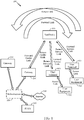
- FIG. 1 illustrates an example of a satellite communication system 100 which includes a plurality of satellites (although only one satellite 300 is shown for clarity of illustration) in non-geosynchronous orbits, for example, low-earth orbits (LEO), a gateway 200 in communication with the satellite 300, a plurality of user terminals (UTs) 400 and 401 in communication with the satellite 300, and a plurality of user equipment (UE) 500 and 501 in communication with the UTs 400 and 401, respectively.
- Each UE 500 or 501 may be a user device such as a mobile device, a telephone, a smartphone, a tablet, a laptop computer, a computer, a wearable device, a smart watch, an audiovisual device, or any device including the capability to communicate with a UT.
- the UE 500 and/or UE 501 may be a device (e.g., access point, small cell, etc.) that is used to communicate to one or more end user devices.
- the UT 400 and the UE 500 communicate with each other via a bidirectional access link (having a forward access link and return access link), and similarly, the UT 401 and the UE 501 communicate with each other via another bidirectional access link.
- one or more additional UE may be configured to receive only and therefore communicate with a UT only using a forward access link.
- one or more additional UE may also communicate with UT 400 or UT 401.
- a UT and a corresponding UE may be integral parts of a single physical device, such as a mobile telephone with an integral satellite transceiver and an antenna for communicating directly with a satellite, for example.
- the gateway 200 may have access to the Internet 108 or one or more other types of public, semiprivate or private networks.
- the gateway 200 is in communication with infrastructure 106, which is capable of accessing the Internet 108 or one or more other types of public, semiprivate or private networks.
- the gateway 200 may also be coupled to various types of communication backhaul, including, for example, landline networks such as optical fiber networks or public switched telephone networks (PSTN) 110.
- PSTN public switched telephone networks
- the gateway 200 may interface to the Internet 108, PSTN 110, or one or more other types of public, semiprivate or private networks without using infrastructure 106.
- gateway 200 may communicate with other gateways, such as gateway 201 through the infrastructure 106 or alternatively may be configured to communicate to gateway 201 without using infrastructure 106.
- Infrastructure 106 may include, in whole or part, a network control center (NCC), a satellite control center (SCC), a wired and/or wireless core network and/or any other components or systems used to facilitate operation of and/or communication with the satellite communication system 100.
- NCC network control center
- SCC satellite control center
- wired and/or wireless core network and/or any other components or systems used to facilitate operation of and/or communication with the satellite communication system 100.
- a signal path from the satellite 300 to a ground station which may be the gateway 200 or one of the UTs 400 and 401, may be generically called a downlink.
- a signal path from a ground station to the satellite 300 may be generically called an uplink.
- signals can have a general directionality such as a forward link and a return link or reverse link.
- a communication link in a direction originating from the gateway 200 and terminating at the UT 400 through the satellite 300 is called a forward link
- a communication link in a direction originating from the UT 400 and terminating at the gateway 200 through the satellite 300 is called a return link or reverse link
- the signal path from the gateway 200 to the satellite 300 is labeled "Forward Feeder Link”
- the signal path from the satellite 300 to the gateway 200 is labeled "Return Feeder Link” in FIG. 1
- the signal path from each UT 400 or 401 to the satellite 300 is labeled "Return Service Link”
- the signal path from the satellite 300 to each UT 400 or 401 is labeled "Forward Service Link” in FIG. 1 .
- FIG. 2 is an example block diagram of gateway 200, which also can apply to gateway 201 of FIG. 1 .
- Gateway 200 is shown to include a number of antennas 205, an RF subsystem 210, a digital subsystem 220, a Public Switched Telephone Network (PSTN) interface 230, a Local Area Network (LAN) interface 240, a gateway interface 245, and a gateway controller 250.
- PSTN Public Switched Telephone Network
- LAN Local Area Network
- Gateway controller 250 is coupled to RF subsystem 210, digital subsystem 220, PSTN interface 230, LAN interface 240, and gateway interface 245.
- each of the RF transceivers 212 may include a transmit chain and a receive chain.
- Each receive chain may include a low noise amplifier (LNA) and a down-converter (e.g., a mixer) to amplify and down-convert, respectively, received communication signals in a well-known manner.
- LNA low noise amplifier
- a down-converter e.g., a mixer
- each receive chain may include an analog-to-digital converter (ADC) to convert the received communication signals from analog signals to digital signals (e.g., for processing by digital subsystem 220).
- ADC analog-to-digital converter
- Each transmit chain may include an up-converter (e.g., a mixer) and a power amplifier (PA) to up-convert and amplify, respectively, communication signals to be transmitted to satellite 300 in a well-known manner.
- each transmit chain may include a digital-to-analog converter (DAC) to convert the digital signals received from digital subsystem 220 to analog signals to be transmitted to satellite 300.
- ADC analog-to-digital converter
- the RF controller 214 may be used to control various aspects of the number of RF transceivers 212 (e.g., selection of the carrier frequency, frequency and phase calibration, gain settings, and the like).
- the antenna controller 216 may control various aspects of the antennas 205 (e.g., beamforming, beam steering, gain settings, frequency tuning, and the like).
- the digital subsystem 220 may include a number of digital receiver modules 222, a number of digital transmitter modules 224, a baseband (BB) processor 226, and a control (CTRL) processor 228.
- Digital subsystem 220 may process communication signals received from RF subsystem 210 and forward the processed communication signals to PSTN interface 230 and/or LAN interface 240, and may process communication signals received from PSTN interface 230 and/or LAN interface 240 and forward the processed communication signals to RF subsystem 210.
- Each digital receiver module 222 may correspond to signal processing elements used to manage communications between gateway 200 and UT 400.
- One of the receive chains of RF transceivers 212 may provide input signals to multiple digital receiver modules 222.
- a number of digital receiver modules 222 may be used to accommodate all of the satellite beams and possible diversity mode signals being handled at any given time.
- each digital receiver module 222 may include one or more digital data receivers, a searcher receiver, and a diversity combiner and decoder circuit.
- the searcher receiver may be used to search for appropriate diversity modes of carrier signals, and may be used to search for pilot signals (or other relatively fixed pattern strong signals).
- the digital transmitter modules 224 may process signals to be transmitted to UT 400 via satellite 300.
- each digital transmitter module 224 may include a transmit modulator that modulates data for transmission.
- the transmission power of each transmit modulator may be controlled by a corresponding digital transmit power controller (not shown for simplicity) that may (1) apply a minimum level of power for purposes of interference reduction and resource allocation and (2) apply appropriate levels of power when needed to compensate for attenuation in the transmission path and other path transfer characteristics.
- the control processor 228, which is coupled to digital receiver modules 222, digital transmitter modules 224, and baseband processor 226, may provide command and control signals to effect functions such as, but not limited to, signal processing, timing signal generation, power control, handoff control, diversity combining, and system interfacing.
- the control processor 228 may also control the generation and power of pilot, synchronization, and paging channel signals and their coupling to the transmit power controller (not shown for simplicity).
- the pilot channel is a signal that is not modulated by data, and may use a repetitive unchanging pattern or non-varying frame structure type (pattern) or tone type input.
- the orthogonal function used to form the channel for the pilot signal generally has a constant value, such as all 1's or 0's, or a well-known repetitive pattern, such as a structured pattern of interspersed 1's and 0's.
- Baseband processor 226 is well known in the art and is therefore not described in detail herein.
- the baseband processor 226 may include a variety of known elements such as (but not limited to) coders, data modems, and digital data switching and storage components.
- the PSTN interface 230 may provide communication signals to, and receive communication signals from, an external PSTN either directly or through additional infrastructure 106, as illustrated in FIG. 1 .
- the PSTN interface 230 is well known in the art, and therefore is not described in detail herein.
- the PSTN interface 230 may be omitted, or may be replaced with any other suitable interface that connects gateway 200 to a ground-based network (e.g., the Internet).
- the LAN interface 240 may provide communication signals to, and receive communication signals from, an external LAN.
- LAN interface 240 may be coupled to the Internet 108 either directly or through additional infrastructure 106, as illustrated in FIG. 1 .
- the LAN interface 240 is well known in the art, and therefore is not described in detail herein.
- the gateway interface 245 may provide communication signals to, and receive communication signals from, one or more other gateways associated with the satellite communication system 100 of FIG. 1 (and/or to/from gateways associated with other satellite communication systems, not shown for simplicity). For some implementations, gateway interface 245 may communicate with other gateways via one or more dedicated communication lines or channels (not shown for simplicity). For other implementations, gateway interface 245 may communicate with other gateways using PSTN 110 and/or other networks such as the Internet 108 (see also FIG. 1 ). For at least one implementation, gateway interface 245 may communicate with other gateways via infrastructure 106.
- the gateway controller 250 may plan and control utilization of satellite 300's resources by gateway 200. For example, the gateway controller 250 may analyze trends, generate traffic plans, allocate satellite resources, monitor (or track) satellite positions, and monitor the performance of gateway 200 and/or satellite 300.
- the gateway controller 250 may also be coupled to a ground-based satellite controller (not shown for simplicity) that maintains and monitors orbits of satellite 300, relays satellite usage information to gateway 200, tracks the positions of satellite 300, and/or adjusts various channel settings of satellite 300.
- the gateway controller 250 includes a local time, frequency, and position references 251, which may provide local time and frequency information to the RF subsystem 210, the digital subsystem 220, and/or the interfaces 230, 240, and 245.
- the time and frequency information may be used to synchronize the various components of gateway 200 with each other and/or with satellite(s) 300.
- the local time, frequency, and position references 251 may also provide position information (e.g., ephemeris data) of satellite(s) 300 to the various components of gateway 200.
- the local time, frequency, and position references 251 may be a separate subsystem that is coupled to gateway controller 250 (and/or to one or more of digital subsystem 220 and RF subsystem 210).
- the gateway controller 250 may also be coupled to a network control center (NCC) and/or a satellite control center (SCC).
- NCC network control center
- SCC satellite control center
- the gateway controller 250 may allow the SCC to communicate directly with satellite(s) 300, for example, to retrieve ephemeris data from satellite(s) 300.
- the gateway controller 250 may also receive processed information (e.g., from the SCC and/or the NCC) that allows gateway controller 250 to properly aim its antennas 205 (e.g., at the appropriate satellite(s) 300), to schedule beam transmissions, to coordinate handovers, and to perform various other well-known functions.
- FIG. 3 is an example block diagram of satellite 300 for illustrative purposes only. It will be appreciated that specific satellite configurations can vary significantly and may or may not include on-board processing. Further, although illustrated as a single satellite, two or more satellites using inter-satellite communication may provide the functional connection between the gateway 200 and UT 400. It will be appreciated that disclosure is not limited to any specific satellite configuration and any satellite or combinations of satellites that can provide the functional connection between the gateway 200 and UT 400 can be considered within the scope of the disclosure.
- satellite 300 is shown to include a forward transponder 310, a return transponder 320, an oscillator 330, a controller 340, forward link antennas 351-352, and return link antennas 361-362.
- the forward transponder 310 which may process communication signals within a corresponding channel or frequency band, may include a respective one of first bandpass filters 311(1)-311(N), a respective one of first LNAs 312(1)-312(N), a respective one of frequency converters 313(1)-313(N), a respective one of second LNAs 314(1)-314(N), a respective one of second bandpass filters 315(1)-315(N), and a respective one of PAs 316(1)-316(N).
- Each of the PAs 316(1)-316(N) is coupled to a respective one of antennas 352(1)-352(N), as shown in FIG. 3 .
- the first bandpass filter 311 passes signal components having frequencies within the channel or frequency band of the respective forward path FP, and filters signal components having frequencies outside the channel or frequency band of the respective forward path FP.
- the pass band of the first bandpass filter 311 corresponds to the width of the channel associated with the respective forward path FP.
- the first LNA 312 amplifies the received communication signals to a level suitable for processing by the frequency converter 313.
- the frequency converter 313 converts the frequency of the communication signals in the respective forward path FP (e.g., to a frequency suitable for transmission from satellite 300 to UT 400).
- the second LNA 314 amplifies the frequency-converted communication signals, and the second bandpass filter 315 filters signal components having frequencies outside of the associated channel width.
- the PA 316 amplifies the filtered signals to a power level suitable for transmission to UTs 400 via respective antenna 352.
- the return transponder 320 which includes a number N of return paths RP(1)-RP(N), receives communication signals from UT 400 along return service link 302R via antennas 361(1)-361(N), and transmits communication signals to gateway 200 along return feeder link 301R via one or more antennas 362.
- Each of the return paths RP(1)-RP(N), which may process communication signals within a corresponding channel or frequency band, may be coupled to a respective one of antennas 361(1)-361(N), and may include a respective one of first bandpass filters 321(1)-321(N), a respective one of first LNAs 322(1)-322(N), a respective one of frequency converters 323(1)-323(N), a respective one of second LNAs 324(1)-324(N), and a respective one of second bandpass filters 325(1)-325(N).
- the first bandpass filter 321 passes signal components having frequencies within the channel or frequency band of the respective return path RP, and filters signal components having frequencies outside the channel or frequency band of the respective return path RP.
- the pass band of the first bandpass filter 321 may for some implementations correspond to the width of the channel associated with the respective return path RP.
- the first LNA 322 amplifies all the received communication signals to a level suitable for processing by the frequency converter 323.
- the frequency converter 323 converts the frequency of the communication signals in the respective return path RP (e.g., to a frequency suitable for transmission from satellite 300 to gateway 200).
- the second LNA 324 amplifies the frequency-converted communication signals, and the second bandpass filter 325 filters signal components having frequencies outside of the associated channel width. Signals from the return paths RP(1)-RP(N) are combined and provided to the one or more antennas 362 via a PA 326. The PA 326 amplifies the combined signals for transmission to the gateway 200.
- Oscillator 330 which may be any suitable circuit or device that generates an oscillating signal, provides a forward local oscillator signal LO(F) to the frequency converters 313(1)-313(N) of forward transponder 310, and provides a return local oscillator signal LO(R) to frequency converters 323(1)-323(N) of return transponder 320.
- the LO(F) signal may be used by frequency converters 313(1)-313(N) to convert communication signals from a frequency band associated with the transmission of signals from gateway 200 to satellite 300 to a frequency band associated with the transmission of signals from satellite 300 to UT 400.
- the LO(R) signal may be used by frequency converters 323(1)-323(N) to convert communication signals from a frequency band associated with the transmission of signals from UT 400 to satellite 300 to a frequency band associated with the transmission of signals from satellite 300 to gateway 200.
- Controller 340 which is coupled to forward transponder 310, return transponder 320, and oscillator 330, may control various operations of satellite 300 including (but not limited to) channel allocations.
- the controller 340 may include a memory coupled to a processor (not shown for simplicity).
- the memory may include a non-transitory computer-readable medium (e.g., one or more nonvolatile memory elements, such as EPROM, EEPROM, Flash memory, a hard drive, etc.) storing instructions that, when executed by the processor, cause the satellite 300 to perform operations including (but not limited to) those described herein.
- FIG. 4 An example of a transceiver for use in the UT 400 or 401 is illustrated in FIG. 4 .
- at least one antenna 410 is provided for receiving forward link communication signals (e.g., from satellite 300), which are transferred to an analog receiver 414, where they are down-converted, amplified, and digitized.
- a duplexer element 412 is often used to allow the same antenna to serve both transmit and receive functions.
- a UT transceiver may employ separate antennas for operating at different transmit and receive frequencies.
- the digital communication signals output by the analog receiver 414 are transferred to at least one digital data receiver 416A and at least one searcher receiver 418. Additional digital data receivers to 416N can be used to obtain desired levels of signal diversity, depending on the acceptable level of transceiver complexity, as would be apparent to one skilled in the relevant art.
- At least one user terminal control processor 420 is coupled to digital data receivers 416A-416N and searcher receiver 418.
- the control processor 420 provides, among other functions, basic signal processing, timing, power and handoff control or coordination, and selection of frequency used for signal carriers. Another basic control function that may be performed by the control processor 420 is the selection or manipulation of functions to be used for processing various signal waveforms.
- Signal processing by the control processor 420 can include a determination of relative signal strength and computation of various related signal parameters. Such computations of signal parameters, such as timing and frequency may include the use of additional or separate dedicated circuitry to provide increased efficiency or speed in measurements or improved allocation of control processing resources.
- the outputs of digital data receivers 416A-416N are coupled to digital baseband circuitry 422 within the user terminal.
- the digital baseband circuitry 422 comprises processing and presentation elements used to transfer information to and from UE 500 as shown in FIG. 1 , for example.
- the digital baseband circuitry 422 may comprise a diversity combiner and decoder. Some of these elements may also operate under the control of, or in communication with, a control processor 420.
- the digital baseband circuitry 422 When voice or other data is prepared as an output message or communications signal originating with the user terminal, the digital baseband circuitry 422 is used to receive, store, process, and otherwise prepare the desired data for transmission.
- the digital baseband circuitry 422 provides this data to a transmit modulator 426 operating under the control of the control processor 420.
- the output of the transmit modulator 426 is transferred to a power controller 428 which provides output power control to a transmit power amplifier 430 for final transmission of the output signal from the antenna 410 to a satellite (e.g., satellite 300).
- the UT transceiver also includes a memory 432 associated with the control processor 420.
- the memory 432 may include instructions for execution by the control processor 420 as well as data for processing by the control processor 420.
- the memory 432 includes instructions to perform some or all of the processes discussed with respect to FIGS. 9 and 11 .
- the UT 400 also includes an optional local time, frequency and/or position references 434 (e.g., a GPS receiver), which may provide local time, frequency and/or position information to the control processor 420 for various applications, including, for example, time and frequency synchronization for the UT 400.
- an optional local time, frequency and/or position references 434 e.g., a GPS receiver
- the control processor 420 may provide local time, frequency and/or position information to the control processor 420 for various applications, including, for example, time and frequency synchronization for the UT 400.
- Digital data receivers 416A-N and searcher receiver 418 are configured with signal correlation elements to demodulate and track specific signals.
- Searcher receiver 418 is used to search for pilot signals, or other relatively fixed pattern strong signals, while digital data receivers 416A-N are used to demodulate other signals associated with detected pilot signals.
- a digital data receiver 416 can be assigned to track the pilot signal after acquisition to accurately determine the ratio of signal chip energies to signal noise, and to formulate pilot signal strength. Therefore, the outputs of these units can be monitored to determine the energy in, or frequency of, the pilot signal or other signals.
- These receivers also employ frequency tracking elements that can be monitored to provide current frequency and timing information to control processor 420 for signals being demodulated.
- the control processor 420 may use such information to determine to what extent the received signals are offset from the oscillator frequency, when scaled to the same frequency band, as appropriate. This and other information related to frequency errors and frequency shifts can be stored in a storage or memory element 432 as desired.
- the control processor 420 may also be coupled to UE interface circuitry 450 to allow communications between UT 400 and one or more UEs.
- UE interface circuitry 450 may be configured as desired for communication with various UE configurations and accordingly may include various transceivers and related components depending on the various communication technologies employed to communicate with the various UEs supported.
- UE interface circuitry 450 may include one or more antennas, a wide area network (WAN) transceiver, a wireless local area network (WLAN) transceiver, a Local Area Network (LAN) interface, a Public Switched Telephone Network (PSTN) interface and/or other known communication technologies configured to communicate with one or more UEs in communication with UT 400.
- WAN wide area network
- WLAN wireless local area network
- LAN Local Area Network
- PSTN Public Switched Telephone Network
- FIG. 5 is a block diagram illustrating an example of UE 500, which also can apply to UE 501 of FIG. 1 .
- the UE 500 as shown in FIG. 5 may be a mobile device, a handheld computer, a tablet, a wearable device, a smart watch, or any type of device capable of interacting with a user, for example. Additionally, the UE may be a network side device that provides connectivity to various ultimate end user devices and/or to various public or private networks.
- the UE 500 may comprise a LAN interface 502, one or more antennas 504, a wide area network (WAN) transceiver 506, a wireless local area network (WLAN) transceiver 508, and a satellite positioning system (SPS) receiver 510.
- WAN wide area network
- WLAN wireless local area network
- SPS satellite positioning system
- the SPS receiver 510 may be compatible with the Global Positioning System (GPS), the Global Navigation Satellite System (GLONASS) and/or any other global or regional satellite based positioning system.
- the UE 500 may include a WLAN transceiver 508, such as a Wi-Fi transceiver, with or without the LAN interface 502, WAN transceiver 506, and/or SPS receiver 510, for example.
- UE 500 may include additional transceivers such as Bluetooth, ZigBee and other known technologies, with or without the LAN interface 502, WAN transceiver 506, WLAN transceiver 508 and/or SPS receiver 510. Accordingly, the elements illustrated for UE 500 are provided merely as an example configuration and are not intended to limit the configuration of UEs in accordance with the various aspects disclosed herein.
- a processor 512 is connected to the LAN interface 502, the WAN transceiver 506, the WLAN transceiver 508 and the SPS receiver 510.
- a motion sensor 514 and other sensors may also be coupled to the processor 512.
- a memory 516 is connected to the processor 512.
- the memory 516 may include data 518 that may be transmitted to and/or received from the UT 400, as shown in FIG. 1 .
- the memory 516 may also include stored instructions 520 to be executed by the processor 512 to perform the process steps for communicating with the UT 400.
- the UE 500 may also include a user interface 522, which may include hardware and software for interfacing inputs or outputs of the processor 512 with the user through light, sound or tactile inputs or outputs, for example.
- the UE 500 includes a microphone/speaker 524, a keypad 526, and a display 528 connected to the user interface 522.
- the user's tactile input or output may be integrated with the display 528 by using a touch-screen display, for example.
- the elements illustrated in FIG. 5 are not intended to limit the configuration of the UEs disclosed herein and it will be appreciated that the elements included in the UE 500 will vary based on the end use of the device and the design choices of the system engineers.
- the UE 500 may be a user device such as a mobile device or external network side device in communication with but separate from the UT 400 as illustrated in FIG. 1 , for example.
- the UE 500 and the UT 400 may be integral parts of a single physical device.
- FIG. 6 illustrates a signal processing system 600 that abstracts some components of a UT or a gateway. Illustrated in FIG. 6 are a processor 602 (the term "processor” is to include multiple processor cores on one or more chips), a memory 604, and a modem 606 coupled to the antenna 608.
- the satellite link 610 may represent any one of the satellite links in FIG. 1 originating from the gateway 200 or the UTs 400 or 401 and terminating at the satellite 300.
- the antenna 610 may be configured for transmitting right-hand polarized electromagnetic radiation or left-hand polarized electromagnetic radiation, and may comprise multiple elements for beam steering.
- a single bus denoted as the bus 612, allows communication among the components in FIG. 6 , but in practice a UT or a gateway may utilize one or more busses and one or more point-to-point interconnects, or other types of interconnection technology.
- the signal processing system 600 may implement one or more protocol stacks, such as for example the protocol stack 614.
- the protocol stack 614 does not show all layers in a typical protocol stack. Illustrated in the protocol stack 614 are the physical layer (PHY) 616, the media access control layer (MAC) 618, and the link layer 620.
- the PHY 616 provides RF (Radio Frequency) modulation and demodulation for signals transmitted and received via the antenna 608, the PHY 616 and MAC 618 provide framing, encoding and decoding (e.g., block coding, convolutional coding, turbo coding), and the link layer 620 provides functionality so that data may be multiplexed and demultiplexed.
- the above functional descriptions of the PHY 616, MAC 618, and the link layer 620 are not meant to be exhaustive or exclusive, but are merely provided to indicate that their functionalities are similar to some of the protocol layers in the Open Systems Interconnection model (OSI) model.
- OSI Open Systems Interconnection model
- link layer 620 are additional layers for accessing the Internet or using voice over Internet Protocol (VoIP), such as for example the Internet Protocol (IP) layer 622 and additional layers, referred to in FIG. 6 as the application and higher layers 624.
- VoIP voice over Internet Protocol
- IP Internet Protocol
- link layer 620 may define other planes.
- the layer in FIG. 6 referred to as the signal and control layers 626 provides additional functionality in the way of a signal plane and a control plane so that a voice call may be set up and various parameters may be set (controlled).
- Some of the functionality of the layers in the protocol stack 614 may be performed by software running on the processor 602, and some of the functionality may be performed by hardware under control of firmware. In some instances, some of the functionality of the layers in the protocol stack 614 may be performed by special purpose hardware, for example application specific integrated circuits (ASIC), or field programmable gate arrays (FPGA). For example, the modem 606 may perform some or all of the functionality of the PHY 616.
- the software for performing some of the functionality of the protocol stack 614, as well as further functionality to be described, may be stored in the memory 604.
- the memory 604 may represent a memory hierarchy, and may be referred to as a non-transitory computer-readable media.
- the signal processing system 600 may implement multiple instances of the protocol stack 614, as well as other protocol stacks to communicate with other devices, such as for example the UE 500 or 501.
- a protocol stack provides functionality to realize multiple physical and logical channels for forward or return links.
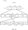
- FIG. 7A illustrates a communication structure 710 for a forward link.
- a plurality of slots is transmitted from the gateway 200 to multiple UTs, where three slots are illustrated: the (n-1) th slot 704, the n th slot 706, and the (n+1) th slot 708.
- a slot represents the smallest unit of transmission time, and its time duration may be referred to as a transmission time interval.
- a slot comprises three components: the pilot 712, the control 714, and the data 716.
- a slot may include other components.
- the pilot 712 comprises a pilot signal that may be used by a UT for synchronization, equalization, channel quality estimation, and so forth.
- the data 716 comprises data payload destined for one or more user terminals, and the control 714 includes information elements to describe the data 716 as discussed below.
- the MAC 618 and PHY 616 can insert multiple blocks into the data 716, where each block is destined for a UT. More than one block in the data 716 may be destined for the same UT. Different blocks may have different lengths. In particular, to achieve flexibility, it is envisioned that various blocks at one time or another will likely occupy varying lengths within the data 716.
- Information elements in the control 714 indicate how many blocks are contained in the data 716, which block belongs to which UT, and the relative positions and lengths of each of the blocks within the data 716. For example, three blocks within data 716 are illustrated: the block(i-1) 718, the block(i) 720, and the block(i+1) 722.
- the information element 724 comprises information relevant to one or more blocks within the data portion of a slot. For example, for the block(i), the information element 724 may provide its relative position and length within the data 716, which UT it is for, the type of coding scheme, and the type of modulation scheme.
- the information element 724 may include information relevant to other blocks, and it is immaterial whether one considers the information element 724 as having a single datum of information regarding a single block, information data regarding a single block, or information data regarding multiple blocks.
- the information element 724 may represent any one of a large number of possible mappings of blocks to user terminals.
- the data 724 in FIG. 7B comprises the five blocks, block(i-2) through block(i+2), for some arbitrary index i.
- the data 724 may include additional blocks. Similar remarks apply to the data 726 illustrated in FIG. 7C .
- the three blocks, block(i-2), block(i-1), and block(i) are mapped to the UT 728, and the two blocks, block(i+1) and block(i+2), are mapped to the UT 730.
- FIG. 7C for the data 726 the five blocks, block(i-2), block(i-1), block(i+1), and block(i+2), are mapped to the UT 732.
- a large number of mappings are possible.
- coding encoding and decoding
- coding schemes may be employed by the PHY 616 of FIG 6 , such as block coding, convolutional or turbo coding, and combinations thereof, such as for example concatenating coding in which an outer code is used with an inner code.
- Interleaving may also be employed, which may be considered to be part of the coding scheme. Consequently, a CRC (Cyclic Redundancy Check) may be generated from the information bits and appended to the information bits for error control.
- CRC Cyclic Redundancy Check
- the PHY 616 translates data symbols (e.g., bits) of a block into channel symbols. For example, every B bits in a block may be grouped together, and each such group mapped to a signal in a signal constellation space comprising at least 2 B signal points.
- the combination of modulation and coding may be represented by a value of an index, which for purposes of this description is referred to as an MCI (Modulation and Coding Index).
- MCI Modulation and Coding Index
- the control 714 in FIG. 7A by way of information elements provides the values of the MCIs for the blocks.
- a UT may employ blind detection and error control in which the MCI for the block it is decoding is not transmitted along with the block. Regardless of whether the MCIs are transmitted or not, different modulation and coding schemes may be employed for the various blocks, so that multiple modulation and coding schemes may be used for multiple blocks in one slot destined for one or more UTs.
- the various satellite communication links may utilize various accessing schemes, such as for example single carrier TDMA.
- the signal constellation space may represent any one of a number of well-known modulation techniques, for example PSK (Phase Shit Keying), QPSK (Quadrature Phase Shift Keying), or different levels of QAM (Quadrature Amplitude Modulation), e.g., 16-QAM, 64-QAM, and so forth.
- PSK Phase Shit Keying
- QPSK Quadrature Phase Shift Keying
- QAM Quadrature Amplitude Modulation
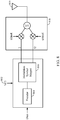
- FIG. 8 illustrates a signal processing chain for the PHY 616 to perform encoding and modulation.
- the encoder 804 encodes the information data, and may implement, as examples, a block encoder, a convolutional or turbo encoder, or a concatenated encoding scheme.
- the encoder 804 may include interleaving.
- the modulation symbol mapper 806 maps bit space into signal constellation space, whereby one or more bits are grouped together and mapped into a modulation symbol, as discussed previously.
- RF (Radio Frequency) modulation symbolized by the RF modulator 808, translates the baseband signal to RF, where the RF output signal is fed to the antenna 810.
- FIG. 8 may illustrate part of a signal processing chain of a UT or a gateway. Furthermore, the modulation and coding scheme used by a UT for transmission may not be the same as that used by a gateway for sending data to that UT.
- a user terminal may determine the channel quality of its satellite communication link based upon various measured parameters, such as for example by measuring the signal-to-noise ratio or by computing a frame error rate (or bit error rate) accumulated over some period of time.
- This channel quality may be encoded into the value of an information element, which may be referred to as the channel state information (CSI).
- the value of the CSI for a UT (e.g., UT 400 or 401) may be transmitted to the gateway 200.
- the gateway 200 assigns to the UT 400 or 401 a value for its MCI where the value is placed in the control 714 and used in the signal processing chain of FIG. 8 as discussed previously.
- the UT 400 or 401 may determine their respective modulation and coding schemes, and in other implementations the gateway 200 may determine modulation and coding schemes.
- the signal processing system 600 may store a lookup table by which values of the CSI map to values of the MCI, so that the appropriate modulation and coding scheme may be determined.
- the modulation and coding scheme may also be varied for re-transmissions of blocks. For example, a relatively high spectral efficiency may be chosen for the initial transmission of a block, whereupon if the sender of the block (e.g., the gateway 200 or the UTs 400 or 401) determines that the block has been lost or received in error, then a new modulation and coding scheme is chosen for the re-transmission of the block to improve the BLER at the expense of spectral efficiency.
- a relatively high spectral efficiency may be chosen for the initial transmission of a block, whereupon if the sender of the block (e.g., the gateway 200 or the UTs 400 or 401) determines that the block has been lost or received in error, then a new modulation and coding scheme is chosen for the re-transmission of the block to improve the BLER at the expense of spectral efficiency.
- the PHY 616 may receive a NAK (negative acknowledgement) and determine that a block has been lost or received in error, in which case the processor 602 running the protocol stack 614 re-sets the MCI 802 so that less spectrally efficient modulation and coding is employed.
- NAK negative acknowledgement
- the processor 602 running the protocol stack 614 re-sets the MCI 802 so that less spectrally efficient modulation and coding is employed.
- a convention may be chosen such that as the MCI value increases, so does the spectral efficiency, or at least, it doesn't decrease. That is, the spectral efficiency as a function of the MCI value may be viewed as an increasing function, but not necessarily a strictly increasing function. In this case, lowering the MCI value implies less spectrally efficient modulation and coding.
- FIG. 9 represents various processes and procedures performed by a gateway and user terminals in a satellite communication system.
- the actions indicated in FIG. 9 although illustrated in an ordered flow diagram, are not necessarily performed in the order indicated in FIG. 9 , nor are all such indicated actions necessarily performed by a gateway or a user terminal. That is, some of the actions indicated in FIG. 9 are optional and need not be performed in a satellite communication system.
- a plurality of user terminals determine their respective CSIs based upon measurements such as signal-to-noise ratio, accumulated bit or frame error rate, or perhaps other parameters that are measured or obtained by the satellite 300.
- the user terminals send the values of their respective CSIs to the gateway 200 using the return link of the satellite communication system.
- the gateway 200 encodes and modulates each block based upon the CSI of its intended (corresponding) UT.
- the gateway may assign to each user terminal a particular modulation and coding scheme, indicated by a value of an MCI, based upon the CSI of that user terminal.
- the modulation and coding scheme may be determined by the gateway 200 without a CSI.
- the gateway 200 transmits in a single slot the blocks that are encoded and modulated in the action 906 destined for the various user terminals, where the modulation and coding scheme for each block is based upon the scheme assigned to it by the gateway 200.
- the plural term "blocks” also includes the singular term "block,” so that in the action 908 there may be only one block in a transmitted slot.
- the user terminals use their assigned modulation and coding schemes (indicated in their respective MCIs) to demodulate and decode their respective blocks.
- the gateway upon re-transmission of that block in another slot may change the modulation and coding scheme, as indicated in the value of the assigned MCI.
- the new modulation and coding scheme (as indicated in a lower value of the MCI) is chosen to reduce the BLER at the expense of a reduction in spectral efficiency.
- a communication system provides flexibility in spectral efficiency for modulation and coding for transmissions and re-transmissions.
- a first modulation and coding scheme is selected for the first transmission of a block, whether by a gateway to a user terminal via a satellite (the forward link), or by a user terminal to a gateway via a satellite (the return link); where if a block is lost or received in error, a second modulation and coding scheme is selected for re-transmission (a second transmission) of the block.
- the first transmission as compared to the second transmission has a relatively higher spectral efficiency.
- the second modulation and coding scheme may employ lower order modulation and lower rate turbo encoding relative to the first modulation and coding scheme.
- the first modulation and coding scheme does not use concatenated coding, but the second modulation and coding scheme may use concatenated coding, where a BCH code is used as an outer code with the turbo code as an inner code.
- a re-transmitted block may occupy a greater portion of a slot than when it was first transmitted. That is, a re-transmission may use more resources in time. For example, with a more robust coding scheme using more error control bits, the extra bits used for error correction results in a block occupying more symbol positions in a transmitted slot than compared to when that block was first transmitted (for the same modulation scheme).
- the first transmitted block may take up a relatively small fraction of a slot, so that upon re-transmission of that block it may be scheduled with fewer other blocks so that it may take up a larger fraction of its slot than when first transmitted, but where nevertheless the re-transmitted block may fit within a single slot.
- a communication system designed to avoid re-segmentation can ensure that a block in a first transmission only occupies a relatively small fraction of a slot. How small this fraction should be may be determined by how much more coding gain is desired in a re-transmission.
- a communication system may be designed so that the first transmission of a block and each successive re-transmission of that block (e.g., a second transmission, a third transmission, and so forth) have a different target BLER.
- a turbo code when used without an outer code has an error floor on the order of 10 -4 .
- First transmissions that have a target BLER of 10 -3 have a target BLER greater than the error floor of the turbo code, so that a turbo code is used without an outer code.
- Re-transmissions that have a target BLER of 10 -6 have a target BLER less than the error floor of the turbo code (when used without an outer code), in which case concatenated coding should be used, for example a turbo code as an inner code and a Bose-Chaudhuri-Hocquenghem (BCH) code as an outer code.
- the concatenated code should have an error floor less than 10 -6 .
- the first transmission of a block occupies a relatively small fraction of the slot.
- the block can take up a larger fraction of the slot compared to its first transmission, without the need to re-segment the block so as to avoid overflowing the slot.
- the communication structure illustrated in FIG. 7A enables the advantage of avoiding segmentation.
- FIG. 10 illustrates a concatenated coding scheme that may be used by a user terminal or a gateway.
- the outer encoder 1002 encodes information bits according to a BCH code
- the inner encoder 1004 encodes the output of the outer encoder 1002 according to a turbo code (which may be termed the inner turbo code).
- the inner decoder 1006 decodes the received bits according to the turbo code implemented by the inner encoder 1004, and the outer decoder 1008 decodes the output of the inner decoder 1006 according to the BCH code implemented by the outer encoder 1002.
- the outer encoder 1002 and the inner encoder 1004 may be viewed as the super encoder 1010, and the inner decoder 1006 and the outer decoder 1008 may be viewed as the super decoder 1012.
- the inner encoder 1004 and the inner decoder 1006 when grouped with the raw channel 1014 as seen by the inner encoder 1004 and the inner decoder 1006 may be viewed as the super channel 1016.
- the table 1018 provides t, the error correcting capability, of the outer BCH code as a function of code block length (CB) in bits and the code rate of the inner turbo code.
- CB code block length
- an outer BCH is not used for a code block length less than or equal to 512 bits.
- using an outer code lowers the error floor at the expense of degraded performance in the waterfall region of the BLER curves.
- FIG. 11 illustrates an ARQ (Automatic Repeat reQuest, or Automatic Repeat Query) method.
- a gateway as well as a UT may implement the method illustrated in FIG. 11 , but for the case of a UT there is no mixing of multiple blocks from multiple UTs within a slot.
- the flexible communication structure illustrated in FIG. 7A allows that the ARQ re-transmissions occur with lower spectral efficiency and without re-segmentation.
- FIG. 11 illustrates actions by which a communication system may implement an adaptive ARQ approach where a first transmission of a block is spectrally more efficient than a re-transmission of the block.
- the actions listed in FIG. 11 pertain to a particular block, where the index n (not the same index n shown in FIG. 7A ) refers to the number of re-transmissions for that block.
- the index n is initialized to 0 as indicated in the action 1100.
- the value of the error floor used in the action 1104 is for the particular modulation and coding scheme selected in the action 1102.
- control is brought to the action 1106, so that the modulation and coding scheme selected in the action 1102 is the scheme that will be used. Otherwise, control is brought to the action 1108 in which concatenated coding is enabled so that an outer code is used.
- the particular outer code selected may depend upon the code that was selected in the action 1102. For example, the code rate of the outer code may depend upon the code selected in the action 1102. Because concatenated coding is enabled, the code that was selected in the action 1102 may now be referred to as an inner code.
- the block is transmitted with the modulation and coding scheme as determined by the previous actions.
- an ACK acknowledgement
- no re-transmission is necessary.
- NAK negative acknowledgement
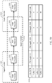
- FIG. 12 illustrates an example of concatenated encoding with an inner turbo code and an outer systematic block code.
- Each block of data (for example, blocks 718, 720, and 722 as illustrated in FIG. 7 and FIG. 12 ) is segmented into sub-blocks that are encoded using a systematic block encoder for the outer encoding and a turbo encoder for the inner encoding.
- the block 720 is provided to the concatenated encoding scheme.
- a CRC Cyclic Redundancy Check
- the appended bits need not necessarily be a CRC, so that other types of check bits may be calculated, but because the algebraic structure of a CRC lends itself to efficient computation it is commonly used in error correction.
- the CRC calculated in the action 1202 is used to declare whether the block 720 when received by a UT has been correctly decoded.
- the block 720 with its appended CRC is segmented into sub-blocks, indicated as B(1), B(2), ..., B(n). Segmentation is performed to match the computational requirements of turbo decoding to the available hardware, so that turbo encoding and turbo decoding is performed on a sub-block by sub-block basis.
- each sub-block is encoded using a systematic block encoder to implement the outer encoding scheme, such as the outer coder illustrated in FIG. 10 .
- a BCH coding scheme is one particular example of a block encoder for the action 1206, although other codes, such as a Reed Solomon code, may be utilized.
- the systematic block encoder in the action 1206 need not be cyclic in its algebraic structure.
- the action 1208, for each sub-block calculates a CRC and appends it to the sub-block.
- the UT receiving a particular sub-block uses the received CRC for that sub-block to determine when to stop the iterations of the turbo decoder.
- the action 1208 is not a requirement.
- each sub-block with its attached CRC is turbo encoded.
- the turbo encoder in the action 1210 provides a stream of systematic bits and parity bits to the circular buffer 1214.
- the rate of the turbo encoder in the action 1210 may be 1/3 so that two parity bits are provided for each systematic bit, although other turbo encoders may be utilized.
- the action 1212 applies a row and column interleave to the output of the turbo encoder.
- the circular buffer 1214 is sampled to provide the appropriate code rate needed for the modulation symbol mapper 806 of FIG. 8 .
- the sampling may include puncturing so that not all of the parity bits provided by the turbo encoder are transmitted, or the circular buffer 1214 may be oversampled in the sense that some of the systematic bits and parity bits are repeated in a transmission.
- the functional units indicated by the actions 1210, 1212, and 1214 may be grouped together, where the grouping may also be referred to as a turbo encoder, as indicated by the dashed box 1215.
- Each such coded sub-block is obtained by applying turbo encoding to a sub-block with its appended CRC, where a sub-block is a subset of a block, such as the block 720.
- the coded sub-block for the sub-block B(k) may be represented in the data structure 1226 by CB(k) for an arbitrary index k, so that for the sub-blocks B(1), B(2), ..., B(n) provided by the segmentation in the action 1204, the turbo encoder 1215 provides the coded sub-blocks CB(1), CB(2), ..., CB(n).
- the action 1216 concatenates the parity bits provided from the systematic block encoder of the action 1206, where the parity block PB represents the concatenation (or grouping) of these parity bits.
- the parity block PB may then be treated in the same way as the systematic bits provided by the systematic block encoder of the action 1206.
- some implementations could segment the parity block PB, depending upon the computational power of the turbo decoder of the intended UT, but for ease of illustration the implementation represented by FIG. 12 does not segment the parity block PB into smaller parity blocks.
- the action 1218 calculates the CRC for the parity block PB and appends it to the parity block PB, although in some implementations the action 1218 could be optional.
- the actions 1220, 1222, and the circular buffer in the action 1224 are essentially equivalent to their counterparts 1210, 1212, and 1214, so that the overall functionality represented in the actions 1220, 1222, and 1224 may be grouped together and considered as the turbo encoder 1225, although the particular turbo code for the turbo encoder 1225 may not be the same as the turbo code for the turbo encoder 1215.
- the output of the circular buffer 1224 (the output of the turbo encoder 1225) may be referred to as a coded parity block CPB.
- the coded sub-blocks from the turbo encoder 1215 and the coded parity block CPB from the turbo encoder 1225 are concatenated and transmitted as the data structure 1226.
- the concatenation of the coded sub-blocks CB(1), CB(2), ..., CB(n) into the data structure 1226 would be the same as if the outer encoder in the action 1206 were absent. Accordingly, the signal processing structures to encode and decode a turbo code without an outer code may be used in the concatenated coding scheme of FIG. 12 .
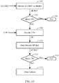
- FIG. 13 illustrates decoding for the concatenated encoding scheme of FIG. 12 .
- the prime in CB(k)' distinguishes a received coded sub-block from the transmitted coded sub-block CB(k).
- the turbo decoder in a UT uses the received CRC in each received coded sub-block CB(k)' to determine when to stop the iterative procedure inherent in turbo decoding.
- FIG. 13 illustrates decoding for the concatenated encoding scheme of FIG. 12 .
- the sub-blocks B(k)' are concatenated together to provide an estimate of the transmitted block and block CRC. That is, concatenating the sub-blocks B(k)' provides an estimate of the transmitted block, for example the block 720 of FIG. 12 , block(i)), and an estimate of the block CRC that was attached to the transmitted block in the action 1202 of FIG. 12 . If in the action 1304 the estimated block CRC passes, then the estimate of the transmitted block is declared to be the transmitted block and the signal processing flow diagram of FIG. 13 may be exited as indicated by the action 1306.
- the action 1308 turbo decodes the received coded parity block CPB', where the prime in CPB' is used to distinguish a received coded parity block from the transmitted coded parity block CPB.
- the output of the turbo decoder in the action 1308 is denoted as PB', an estimate of the parity block PB obtained in the actions 1206 and 1216.
- the actions 1308 and 1302 are indicated as separate actions in the signal processing diagram of FIG. 13 , in practice the same signal processing structure may be used for both actions.
- B(n)'PB'] to provide the outer decoded sub-blocks B(k)", k 1, 2, ..., n, where the double prime denotes that inner turbo decoding and outer decoding have been applied to the received coded sub-blocks CB(k)'.
- the signal processing structure for the action 1304 may be used for the action 1312.
- the (second) estimated block CRC passes, then it is assumed that the received block has been correctly decoded and is available to higher layers in the protocol stack, as indicated by the action 1314.
- the (second) estimated block CRC fails, then as indicated in box 1316 other actions may be taken.
- the UT may send a NAK message so that the gateway may transmit the data structure 1226 again, or the received data may be dropped.
- the action 1218 is repeated so that a CRC is calculated and appended to each parity block, followed by turbo encoding of each parity block with appended CRC.
- the data structure 1226 would then include multiple coded parity blocks.
- the action 1308 is repeated for each received coded parity block associated with a received block (i.e., received data structure 1226).
- the decoded parity blocks are then used in the action 1310 for outer decoding.
- the PHY 616 and MAC 618 layers of the signal processing system 600 of FIG. 6 may perform the signal processing actions indicated in FIGS. 12 and 13 , where for the actions of FIG. 12 the signal processing system 600 is in a gateway, such as for example the gateway 200 in FIG. 1 , and for the actions of FIG. 13 the signal processing system 600 is in a UT, such for example the UT 400 in FIG. 1 (or any of the other user terminals).
- FIG. 14 illustrates an example gateway apparatus 1400 represented as a series of interrelated functional modules as discussed with respect to the examples of FIGS. 6 - 11 .
- a module for receiving channel state information 1402 may correspond at least in some aspects to, for example, a signal processing system or a component thereof as discussed herein (e.g., the signal processing system 600 of FIG. 6 or the like).
- a module for encoding a plurality of blocks 1404 may correspond at least in some aspects to, for example, a signal processing system or a component thereof as discussed herein (e.g., the signal processing system 600 of FIG. 6 or the like).
- a module for modulating encoded blocks into modulated and encoded blocks 1406 may correspond at least in some aspects to, for example, a signal processing system or a component thereof as discussed herein (e.g., the signal processing system 600 of FIG. 6 or the like).
- a module for transmitting a slot comprising the modulated and encoded blocks 1408 may correspond at least in some aspects to, for example, a signal processing system or a component thereof as discussed herein (e.g., the signal processing system 600 of FIG. 6 or the like).
- FIG. 15 illustrates another example gateway apparatus 1500 represented as a series of interrelated functional modules as discussed with respect to the examples of FIG. 12 and FIG. 13 .
- a module for providing a block check and appending a block check to the block 1502 may correspond at least in some aspects to, for example, a signal processing system or a component thereof as discussed herein (e.g., the signal processing system 600 of FIG. 6 or the like).
- a module for segmenting a block with an appended block check into one or more sub-blocks 1504 may correspond at least in some aspects to, for example, a signal processing system or a component thereof as discussed herein (e.g., the signal processing system 600 of FIG. 6 or the like).
- a module for encoding a sub-block with a systematic encoder to provide parity bits 1506 may correspond at least in some aspects to, for example, a signal processing system or a component thereof as discussed herein (e.g., the signal processing system 600 of FIG. 6 or the like).
- a module for providing a sub-block check for each sub-block and appending the corresponding sub-block checks 1508 may correspond at least in some aspects to, for example, a signal processing system or a component thereof as discussed herein (e.g., the signal processing system 600 of FIG. 6 or the like).
- a module for turbo encoding sub-blocks with appended sub-block checks to provide coded sub-blocks 1510 may correspond at least in some aspects to, for example, a signal processing system or a component thereof as discussed herein (e.g., the signal processing system 600 of FIG. 6 or the like).
- a module for grouping parity bits into parity blocks 1512 may correspond at least in some aspects to, for example, a signal processing system or a component thereof as discussed herein (e.g., the signal processing system 600 of FIG. 6 or the like).
- a module for providing parity block checks for parity blocks and appending the corresponding parity block checks 1514 may correspond at least in some aspects to, for example, a signal processing system or a component thereof as discussed herein (e.g., the signal processing system 600 of FIG. 6 or the like).
- a module for turbo encoding the parity blocks with appended parity block checks to provide coded parity blocks 1516 may correspond at least in some aspects to, for example, a signal processing system or a component thereof as discussed herein (e.g., the signal processing system 600 of FIG. 6 or the like).
- a module for transmitting the concatenation of coded sub-blocks with coded parity blocks 1518 may correspond at least in some aspects to, for example, a signal processing system or a component thereof as discussed herein (e.g., the signal processing system 600 of FIG. 6 or the like).
- FIG. 16 illustrates an example user terminal apparatus 1600 represented as a series of interrelated functional modules as discussed with respect to the examples of FIG. 12 and FIG. 13 .
- a module for turbo decoding coded sub-blocks to provide a first estimate of a sub-block 1602 may correspond at least in some aspects to, for example, a signal processing system or a component thereof as discussed herein (e.g., the signal processing system 600 of FIG. 6 or the like).
- a module for concatenating the first estimate of a sub-block to provide a first estimate of a block with a first estimate of a block check 1604 may correspond at least in some aspects to, for example, a signal processing system or a component thereof as discussed herein (e.g., the signal processing system 600 of FIG. 6 or the like).
- a module for determining whether the first estimate of a block check passes or fails 1606 may correspond at least in some aspects to, for example, a signal processing system or a component thereof as discussed herein (e.g., the signal processing system 600 of FIG. 6 or the like).
- a module for turbo decoding a received coded parity block to provide an estimate of parity blocks when the first estimate of the block check fails 1608 may correspond at least in some aspects to, for example, a signal processing system or a component thereof as discussed herein (e.g., the signal processing system 600 of FIG. 6 or the like).
- a module for outer decoding the first estimate of a sub-block using the estimate of parity blocks to provide a second estimate of the sub-block when the first estimate of the block check fails 1610 may correspond at least in some aspects to, for example, a signal processing system or a component thereof as discussed herein (e.g., the signal processing system 600 of FIG. 6 or the like).
- a module for concatenating the second estimate of a sub-block to provide a second estimate of the block with a second estimate of the block check when the first estimate of the block check fails 1612 may correspond at least in some aspects to, for example, a signal processing system or a component thereof as discussed herein (e.g., the signal processing system 600 of FIG. 6 or the like).
- a module for determining whether the second estimate of a block check passes or fails when the first estimate of the block check fails 1614 may correspond at least in some aspects to, for example, a signal processing system or a component thereof as discussed herein (e.g., the signal processing system 600 of FIG. 6 or the like).
- the functionality of the modules of FIGS. 14 , 15 , and 16 may be implemented in various ways consistent with the teachings herein.
- the functionality of these modules may be implemented as one or more electrical components.
- the functionality of these blocks may be implemented as a processing system including one or more processor components.
- the functionality of these modules may be implemented using, for example, at least a portion of one or more integrated circuits (e.g., an ASIC).
- an integrated circuit may include a processor, software, other related components, or some combination thereof.
- the functionality of different modules may be implemented, for example, as different subsets of an integrated circuit, as different subsets of a set of software modules, or a combination thereof.
- a given subset e.g., of an integrated circuit and/or of a set of software modules
- FIGS. 14 , 15 , and 16 may be implemented using any suitable means. Such means also may be implemented, at least in part, using corresponding structure as taught herein.
- the components described above in conjunction with the "module for" components of FIGS. 14 , 15 , and 16 also may correspond to similarly designated “means for” functionality.
- one or more of such means may be implemented using one or more of processor components, integrated circuits, or other suitable structure as taught herein.
- a software module may reside in RAM memory, flash memory, ROM memory, EPROM memory, EEPROM memory, registers, hard disk, a removable disk, a CD-ROM, or any other form of storage medium known in the art.
- An exemplary storage medium is coupled to the processor such that the processor can read information from, and write information to, the storage medium. In the alternative, the storage medium may be integral to the processor.
- aspects of the claimed subject matter may include a non-transitory computer-readable media embodying a method for spectral efficient data transmission in satellite systems. Accordingly, the claimed subject matter is not limited to illustrated examples.
Landscapes
- Engineering & Computer Science (AREA)
- Signal Processing (AREA)
- Computer Networks & Wireless Communication (AREA)
- Physics & Mathematics (AREA)
- Aviation & Aerospace Engineering (AREA)
- General Physics & Mathematics (AREA)
- Astronomy & Astrophysics (AREA)
- Quality & Reliability (AREA)
- Probability & Statistics with Applications (AREA)
- Theoretical Computer Science (AREA)
- Radio Relay Systems (AREA)
- Detection And Prevention Of Errors In Transmission (AREA)
- Mobile Radio Communication Systems (AREA)
- Error Detection And Correction (AREA)
Applications Claiming Priority (4)
| Application Number | Priority Date | Filing Date | Title |
|---|---|---|---|
| US201562136224P | 2015-03-20 | 2015-03-20 | |
| US201562196277P | 2015-07-23 | 2015-07-23 | |
| US14/865,590 US9893800B2 (en) | 2015-03-20 | 2015-09-25 | Method and apparatus for spectral efficient data transmission in satellite systems |
| PCT/US2016/022176 WO2016153822A1 (en) | 2015-03-20 | 2016-03-11 | Method and apparatus for spectral efficient data transmission in satellite systems |
Publications (2)
| Publication Number | Publication Date |
|---|---|
| EP3272033A1 EP3272033A1 (en) | 2018-01-24 |
| EP3272033B1 true EP3272033B1 (en) | 2021-10-20 |
Family
ID=56925701
Family Applications (1)
| Application Number | Title | Priority Date | Filing Date |
|---|---|---|---|
| EP16716330.2A Active EP3272033B1 (en) | 2015-03-20 | 2016-03-11 | Method and apparatus for spectral efficient data transmission in satellite systems |
Country Status (8)
| Country | Link |
|---|---|
| US (2) | US9893800B2 (ja) |
| EP (1) | EP3272033B1 (ja) |
| JP (2) | JP6674475B2 (ja) |
| KR (1) | KR101910311B1 (ja) |
| CN (1) | CN107431532A (ja) |
| BR (1) | BR112017020083B1 (ja) |
| SG (1) | SG11201706052YA (ja) |
| WO (1) | WO2016153822A1 (ja) |
Families Citing this family (29)
| Publication number | Priority date | Publication date | Assignee | Title |
|---|---|---|---|---|
| US9893800B2 (en) | 2015-03-20 | 2018-02-13 | Qualcomm Incorporated | Method and apparatus for spectral efficient data transmission in satellite systems |
| US10944471B2 (en) | 2015-06-17 | 2021-03-09 | Hughes Network Systems, Llc | System and method for providing high throughput data services using MEO and LEO satellite systems |
| US11483877B2 (en) * | 2015-06-17 | 2022-10-25 | Hughes Network Systems, Llc | Approaches for high speed global packet data services for LEO/MEO satellite systems |
| MY191476A (en) * | 2015-07-31 | 2022-06-28 | Viasat Inc | Flexible capacity satellite constellation |
| US9991949B2 (en) * | 2016-04-21 | 2018-06-05 | University Of Louisiana At Lafayette | Experimental smartphone ground station grid system and method |
| US10312996B2 (en) * | 2016-09-30 | 2019-06-04 | Hughes Network Systems, Llc | Systems and methods for using adaptive coding and modulation in a regenerative satellite communication system |
| GB2557628B (en) | 2016-12-13 | 2020-01-01 | Inmarsat Global Ltd | Forward link power control |
| CN108712200B (zh) * | 2018-03-29 | 2021-08-10 | 航天东方红卫星有限公司 | 一种小卫星智能无线星务系统及控制方法 |
| CN112154621B (zh) * | 2018-04-03 | 2023-10-10 | 交互数字专利控股公司 | 用于非地面网络的混合自动重复请求(harq) |
| CN113366872A (zh) | 2018-10-24 | 2021-09-07 | 星盟国际有限公司 | 利用并行级联卷积码的lpwan通信协议设计 |
| US10812216B2 (en) | 2018-11-05 | 2020-10-20 | XCOM Labs, Inc. | Cooperative multiple-input multiple-output downlink scheduling |
| US10432272B1 (en) | 2018-11-05 | 2019-10-01 | XCOM Labs, Inc. | Variable multiple-input multiple-output downlink user equipment |
| US10659112B1 (en) | 2018-11-05 | 2020-05-19 | XCOM Labs, Inc. | User equipment assisted multiple-input multiple-output downlink configuration |
| US10756860B2 (en) | 2018-11-05 | 2020-08-25 | XCOM Labs, Inc. | Distributed multiple-input multiple-output downlink configuration |
| CA3119325C (en) | 2018-11-27 | 2023-07-04 | XCOM Labs, Inc. | Non-coherent cooperative multiple-input multiple-output communications |
| US10756795B2 (en) | 2018-12-18 | 2020-08-25 | XCOM Labs, Inc. | User equipment with cellular link and peer-to-peer link |
| US11063645B2 (en) | 2018-12-18 | 2021-07-13 | XCOM Labs, Inc. | Methods of wirelessly communicating with a group of devices |
| CN113242086B (zh) * | 2019-01-23 | 2022-12-09 | 长沙天仪空间科技研究院有限公司 | 一种通信卫星 |
| US11330649B2 (en) | 2019-01-25 | 2022-05-10 | XCOM Labs, Inc. | Methods and systems of multi-link peer-to-peer communications |
| US10756767B1 (en) | 2019-02-05 | 2020-08-25 | XCOM Labs, Inc. | User equipment for wirelessly communicating cellular signal with another user equipment |
| CN111726744B (zh) * | 2019-03-21 | 2023-02-17 | 大唐移动通信设备有限公司 | 一种随机接入方法、装置及终端 |
| US10686502B1 (en) | 2019-04-29 | 2020-06-16 | XCOM Labs, Inc. | Downlink user equipment selection |
| US10735057B1 (en) | 2019-04-29 | 2020-08-04 | XCOM Labs, Inc. | Uplink user equipment selection |
| US11411778B2 (en) | 2019-07-12 | 2022-08-09 | XCOM Labs, Inc. | Time-division duplex multiple input multiple output calibration |
| US10924203B1 (en) * | 2019-07-26 | 2021-02-16 | Hughes Network Systems, Llc | On-the-fly inroute adaptive modulation |
| US11700424B2 (en) * | 2019-12-31 | 2023-07-11 | Hughes Network Systems, Llc | DVB-S2 downlink ACM algorithm enhancement to improve data throughput |
| US11411779B2 (en) | 2020-03-31 | 2022-08-09 | XCOM Labs, Inc. | Reference signal channel estimation |
| CN111641445B (zh) * | 2020-04-17 | 2021-12-07 | 中国人民解放军军事科学院国防科技创新研究院 | 卫星通信与导航一体化处理系统及方法 |
| CN114867082B (zh) * | 2022-03-31 | 2024-04-05 | 国网江苏省电力有限公司电力科学研究院 | 一种大规模电力物联网设备免授权接入系统及方法 |
Citations (1)
| Publication number | Priority date | Publication date | Assignee | Title |
|---|---|---|---|---|
| EP2637432A1 (en) * | 2010-11-04 | 2013-09-11 | Fujitsu Limited | Wireless communication method, relay station, mobile station and mobile communication system |
Family Cites Families (27)
| Publication number | Priority date | Publication date | Assignee | Title |
|---|---|---|---|---|
| US4344171A (en) | 1980-12-11 | 1982-08-10 | International Business Machines Corporation | Effective error control scheme for satellite communications |
| GB2384394A (en) | 2002-01-18 | 2003-07-23 | Inmarsat Ltd | Adapting transmission parameters to link conditions |
| US7287206B2 (en) * | 2002-02-13 | 2007-10-23 | Interdigital Technology Corporation | Transport block set transmission using hybrid automatic repeat request |
| US6744766B2 (en) | 2002-06-05 | 2004-06-01 | Meshnetworks, Inc. | Hybrid ARQ for a wireless Ad-Hoc network and a method for using the same |
| US7203490B2 (en) | 2003-03-24 | 2007-04-10 | Atc Technologies, Llc | Satellite assisted push-to-send radioterminal systems and methods |
| JP2004304268A (ja) | 2003-03-28 | 2004-10-28 | Matsushita Electric Ind Co Ltd | 無線送信装置、無線受信装置及び方法 |
| PL1949584T3 (pl) | 2005-10-28 | 2019-09-30 | Viasat, Inc. | Adaptacyjne kodowanie i modulacja danych przesyłanych infrastrukturą szerokopasmową |
| US7630682B2 (en) | 2006-01-04 | 2009-12-08 | Globalstar, Inc. | Satellite communication system employing a combination of time slots and orthogonal codes |
| FR2905045B1 (fr) * | 2006-08-17 | 2011-09-02 | Cit Alcatel | Dispositif de traitement pour la transmission de mesures effectuees par des terminaux radio |
| WO2008097367A2 (en) * | 2006-10-03 | 2008-08-14 | Viasat, Inc. | Forward satellite link with sub-channels |
| EP2074769A2 (en) * | 2006-10-06 | 2009-07-01 | ViaSat, Inc. | Dynamic feedback for outbound link rate adjustment in multi-rate downstream |
| EP1944896A1 (en) | 2007-01-09 | 2008-07-16 | Matsushita Electric Industrial Co., Ltd. | Configuration of control channels in a mobile communication system |
| US8660481B2 (en) * | 2007-03-21 | 2014-02-25 | Viasat, Inc. | Techniques for providing broadcast services on spot beam satellites |
| US7853857B2 (en) * | 2007-09-14 | 2010-12-14 | Motorola Mobility, Inc. | Multi-layer cyclic redundancy check code in wireless communication system |
| US9083474B2 (en) * | 2008-04-25 | 2015-07-14 | Qualcomm Incorporated | Multimedia broadcast forwarding systems and methods |
| CN101282204B (zh) * | 2008-05-13 | 2011-04-27 | 山东大学 | 基于自适应编码调制的自适应协作重传方法 |
| WO2010001610A1 (ja) | 2008-07-02 | 2010-01-07 | パナソニック株式会社 | 消失訂正符号化装置及び消失訂正符号化方法 |
| CN102763361B (zh) | 2010-02-12 | 2016-04-27 | 交互数字专利控股公司 | 发送用于多个下行链路载波的反馈 |
| KR20120065130A (ko) | 2010-12-10 | 2012-06-20 | 한국전자통신연구원 | 위성 시스템의 리턴 링크에서의 신호 복조방법 및 그 복조장치, 리턴 링크에서의 신호 변조방법 및 그 변조 장치 |
| JP2013021544A (ja) | 2011-07-12 | 2013-01-31 | Fujitsu Ltd | 無線通信システム、無線通信装置及び無線通信方法 |
| US8797966B2 (en) | 2011-09-23 | 2014-08-05 | Ofinno Technologies, Llc | Channel state information transmission |
| KR20130050718A (ko) | 2011-11-08 | 2013-05-16 | 한국전자통신연구원 | 기상 데이터를 토대로 하는 채널 예측 방법 및 그 장치 |
| KR101687047B1 (ko) | 2012-08-22 | 2016-12-15 | 한국전자통신연구원 | 위성통신용 포워드링크의 적응형 코딩 변조장치 및 방법 |
| JP6101544B2 (ja) * | 2013-04-05 | 2017-03-22 | 京セラ株式会社 | 基地局、通信制御方法、及びプロセッサ |
| FR3006133B1 (fr) * | 2013-05-24 | 2016-09-02 | Thales Sa | Procede de decodage d'un code correcteur, par exemple un turbo-code, par analyse du spectre etendu des mots du code |
| US9491269B2 (en) * | 2014-04-11 | 2016-11-08 | Apple Inc. | Uplink transmission rate in a wireless communication device |
| US9893800B2 (en) | 2015-03-20 | 2018-02-13 | Qualcomm Incorporated | Method and apparatus for spectral efficient data transmission in satellite systems |
-
2015
- 2015-09-25 US US14/865,590 patent/US9893800B2/en active Active
-
2016
- 2016-03-11 CN CN201680016610.8A patent/CN107431532A/zh active Pending
- 2016-03-11 SG SG11201706052YA patent/SG11201706052YA/en unknown
- 2016-03-11 BR BR112017020083-0A patent/BR112017020083B1/pt active IP Right Grant
- 2016-03-11 WO PCT/US2016/022176 patent/WO2016153822A1/en active Application Filing
- 2016-03-11 KR KR1020177026307A patent/KR101910311B1/ko active IP Right Grant
- 2016-03-11 JP JP2017548407A patent/JP6674475B2/ja not_active Expired - Fee Related
- 2016-03-11 EP EP16716330.2A patent/EP3272033B1/en active Active
-
2018
- 2018-01-18 US US15/874,361 patent/US10454569B2/en active Active
-
2019
- 2019-12-09 JP JP2019222101A patent/JP2020092425A/ja active Pending
Patent Citations (1)
| Publication number | Priority date | Publication date | Assignee | Title |
|---|---|---|---|---|
| EP2637432A1 (en) * | 2010-11-04 | 2013-09-11 | Fujitsu Limited | Wireless communication method, relay station, mobile station and mobile communication system |
Also Published As
| Publication number | Publication date |
|---|---|
| US20160277096A1 (en) | 2016-09-22 |
| JP6674475B2 (ja) | 2020-04-01 |
| SG11201706052YA (en) | 2017-10-30 |
| US10454569B2 (en) | 2019-10-22 |
| EP3272033A1 (en) | 2018-01-24 |
| WO2016153822A1 (en) | 2016-09-29 |
| US9893800B2 (en) | 2018-02-13 |
| JP2020092425A (ja) | 2020-06-11 |
| BR112017020083A2 (pt) | 2018-06-05 |
| CN107431532A (zh) | 2017-12-01 |
| KR20170128341A (ko) | 2017-11-22 |
| JP2018515955A (ja) | 2018-06-14 |
| US20180198518A1 (en) | 2018-07-12 |
| BR112017020083B1 (pt) | 2024-01-02 |
| KR101910311B1 (ko) | 2018-10-19 |
Similar Documents
| Publication | Publication Date | Title |
|---|---|---|
| US10454569B2 (en) | Method and apparatus for spectral efficient data transmission in satellite systems | |
| EP3642975B1 (en) | Method and apparatus for multiplexing hybrid satellite constellations | |
| US10211909B2 (en) | Link adaptation with RF intermediary element | |
| US8620230B2 (en) | Wireless network architecture and method for base station utilization | |
| JP5318299B2 (ja) | 中継装置および中継補助装置 | |
| JP6600101B2 (ja) | 非対称的な順方向リンクおよび逆方向リンクのサブフレーム分割 |
Legal Events
| Date | Code | Title | Description |
|---|---|---|---|
| STAA | Information on the status of an ep patent application or granted ep patent |
Free format text: STATUS: THE INTERNATIONAL PUBLICATION HAS BEEN MADE |
|
| PUAI | Public reference made under article 153(3) epc to a published international application that has entered the european phase |
Free format text: ORIGINAL CODE: 0009012 |
|
| STAA | Information on the status of an ep patent application or granted ep patent |
Free format text: STATUS: REQUEST FOR EXAMINATION WAS MADE |
|
| 17P | Request for examination filed |
Effective date: 20170802 |
|
| AK | Designated contracting states |
Kind code of ref document: A1 Designated state(s): AL AT BE BG CH CY CZ DE DK EE ES FI FR GB GR HR HU IE IS IT LI LT LU LV MC MK MT NL NO PL PT RO RS SE SI SK SM TR |
|
| AX | Request for extension of the european patent |
Extension state: BA ME |
|
| DAV | Request for validation of the european patent (deleted) | ||
| DAX | Request for extension of the european patent (deleted) | ||
| STAA | Information on the status of an ep patent application or granted ep patent |
Free format text: STATUS: EXAMINATION IS IN PROGRESS |
|
| 17Q | First examination report despatched |
Effective date: 20191121 |
|
| STAA | Information on the status of an ep patent application or granted ep patent |
Free format text: STATUS: EXAMINATION IS IN PROGRESS |
|
| GRAP | Despatch of communication of intention to grant a patent |
Free format text: ORIGINAL CODE: EPIDOSNIGR1 |
|
| STAA | Information on the status of an ep patent application or granted ep patent |
Free format text: STATUS: GRANT OF PATENT IS INTENDED |
|
| INTG | Intention to grant announced |
Effective date: 20210507 |
|
| GRAS | Grant fee paid |
Free format text: ORIGINAL CODE: EPIDOSNIGR3 |
|
| GRAA | (expected) grant |
Free format text: ORIGINAL CODE: 0009210 |
|
| STAA | Information on the status of an ep patent application or granted ep patent |
Free format text: STATUS: THE PATENT HAS BEEN GRANTED |
|
| AK | Designated contracting states |
Kind code of ref document: B1 Designated state(s): AL AT BE BG CH CY CZ DE DK EE ES FI FR GB GR HR HU IE IS IT LI LT LU LV MC MK MT NL NO PL PT RO RS SE SI SK SM TR |
|
| REG | Reference to a national code |
Ref country code: GB Ref legal event code: FG4D |
|
| REG | Reference to a national code |
Ref country code: CH Ref legal event code: EP |
|
| REG | Reference to a national code |
Ref country code: IE Ref legal event code: FG4D |
|
| REG | Reference to a national code |
Ref country code: DE Ref legal event code: R096 Ref document number: 602016065089 Country of ref document: DE |
|
| REG | Reference to a national code |
Ref country code: AT Ref legal event code: REF Ref document number: 1440781 Country of ref document: AT Kind code of ref document: T Effective date: 20211115 |
|
| REG | Reference to a national code |
Ref country code: LT Ref legal event code: MG9D |
|
| REG | Reference to a national code |
Ref country code: NL Ref legal event code: MP Effective date: 20211020 |
|
| REG | Reference to a national code |
Ref country code: AT Ref legal event code: MK05 Ref document number: 1440781 Country of ref document: AT Kind code of ref document: T Effective date: 20211020 |
|
| PG25 | Lapsed in a contracting state [announced via postgrant information from national office to epo] |
Ref country code: RS Free format text: LAPSE BECAUSE OF FAILURE TO SUBMIT A TRANSLATION OF THE DESCRIPTION OR TO PAY THE FEE WITHIN THE PRESCRIBED TIME-LIMIT Effective date: 20211020 Ref country code: LT Free format text: LAPSE BECAUSE OF FAILURE TO SUBMIT A TRANSLATION OF THE DESCRIPTION OR TO PAY THE FEE WITHIN THE PRESCRIBED TIME-LIMIT Effective date: 20211020 Ref country code: FI Free format text: LAPSE BECAUSE OF FAILURE TO SUBMIT A TRANSLATION OF THE DESCRIPTION OR TO PAY THE FEE WITHIN THE PRESCRIBED TIME-LIMIT Effective date: 20211020 Ref country code: BG Free format text: LAPSE BECAUSE OF FAILURE TO SUBMIT A TRANSLATION OF THE DESCRIPTION OR TO PAY THE FEE WITHIN THE PRESCRIBED TIME-LIMIT Effective date: 20220120 Ref country code: AT Free format text: LAPSE BECAUSE OF FAILURE TO SUBMIT A TRANSLATION OF THE DESCRIPTION OR TO PAY THE FEE WITHIN THE PRESCRIBED TIME-LIMIT Effective date: 20211020 |
|
| PG25 | Lapsed in a contracting state [announced via postgrant information from national office to epo] |
Ref country code: IS Free format text: LAPSE BECAUSE OF FAILURE TO SUBMIT A TRANSLATION OF THE DESCRIPTION OR TO PAY THE FEE WITHIN THE PRESCRIBED TIME-LIMIT Effective date: 20220220 Ref country code: SE Free format text: LAPSE BECAUSE OF FAILURE TO SUBMIT A TRANSLATION OF THE DESCRIPTION OR TO PAY THE FEE WITHIN THE PRESCRIBED TIME-LIMIT Effective date: 20211020 Ref country code: PT Free format text: LAPSE BECAUSE OF FAILURE TO SUBMIT A TRANSLATION OF THE DESCRIPTION OR TO PAY THE FEE WITHIN THE PRESCRIBED TIME-LIMIT Effective date: 20220221 Ref country code: PL Free format text: LAPSE BECAUSE OF FAILURE TO SUBMIT A TRANSLATION OF THE DESCRIPTION OR TO PAY THE FEE WITHIN THE PRESCRIBED TIME-LIMIT Effective date: 20211020 Ref country code: NO Free format text: LAPSE BECAUSE OF FAILURE TO SUBMIT A TRANSLATION OF THE DESCRIPTION OR TO PAY THE FEE WITHIN THE PRESCRIBED TIME-LIMIT Effective date: 20220120 Ref country code: NL Free format text: LAPSE BECAUSE OF FAILURE TO SUBMIT A TRANSLATION OF THE DESCRIPTION OR TO PAY THE FEE WITHIN THE PRESCRIBED TIME-LIMIT Effective date: 20211020 Ref country code: LV Free format text: LAPSE BECAUSE OF FAILURE TO SUBMIT A TRANSLATION OF THE DESCRIPTION OR TO PAY THE FEE WITHIN THE PRESCRIBED TIME-LIMIT Effective date: 20211020 Ref country code: HR Free format text: LAPSE BECAUSE OF FAILURE TO SUBMIT A TRANSLATION OF THE DESCRIPTION OR TO PAY THE FEE WITHIN THE PRESCRIBED TIME-LIMIT Effective date: 20211020 Ref country code: GR Free format text: LAPSE BECAUSE OF FAILURE TO SUBMIT A TRANSLATION OF THE DESCRIPTION OR TO PAY THE FEE WITHIN THE PRESCRIBED TIME-LIMIT Effective date: 20220121 Ref country code: ES Free format text: LAPSE BECAUSE OF FAILURE TO SUBMIT A TRANSLATION OF THE DESCRIPTION OR TO PAY THE FEE WITHIN THE PRESCRIBED TIME-LIMIT Effective date: 20211020 |
|
| REG | Reference to a national code |
Ref country code: DE Ref legal event code: R097 Ref document number: 602016065089 Country of ref document: DE |
|
| PG25 | Lapsed in a contracting state [announced via postgrant information from national office to epo] |
Ref country code: SM Free format text: LAPSE BECAUSE OF FAILURE TO SUBMIT A TRANSLATION OF THE DESCRIPTION OR TO PAY THE FEE WITHIN THE PRESCRIBED TIME-LIMIT Effective date: 20211020 Ref country code: SK Free format text: LAPSE BECAUSE OF FAILURE TO SUBMIT A TRANSLATION OF THE DESCRIPTION OR TO PAY THE FEE WITHIN THE PRESCRIBED TIME-LIMIT Effective date: 20211020 Ref country code: RO Free format text: LAPSE BECAUSE OF FAILURE TO SUBMIT A TRANSLATION OF THE DESCRIPTION OR TO PAY THE FEE WITHIN THE PRESCRIBED TIME-LIMIT Effective date: 20211020 Ref country code: EE Free format text: LAPSE BECAUSE OF FAILURE TO SUBMIT A TRANSLATION OF THE DESCRIPTION OR TO PAY THE FEE WITHIN THE PRESCRIBED TIME-LIMIT Effective date: 20211020 Ref country code: DK Free format text: LAPSE BECAUSE OF FAILURE TO SUBMIT A TRANSLATION OF THE DESCRIPTION OR TO PAY THE FEE WITHIN THE PRESCRIBED TIME-LIMIT Effective date: 20211020 Ref country code: CZ Free format text: LAPSE BECAUSE OF FAILURE TO SUBMIT A TRANSLATION OF THE DESCRIPTION OR TO PAY THE FEE WITHIN THE PRESCRIBED TIME-LIMIT Effective date: 20211020 |
|
| PLBE | No opposition filed within time limit |
Free format text: ORIGINAL CODE: 0009261 |
|
| STAA | Information on the status of an ep patent application or granted ep patent |
Free format text: STATUS: NO OPPOSITION FILED WITHIN TIME LIMIT |
|
| 26N | No opposition filed |
Effective date: 20220721 |
|
| PG25 | Lapsed in a contracting state [announced via postgrant information from national office to epo] |
Ref country code: MC Free format text: LAPSE BECAUSE OF FAILURE TO SUBMIT A TRANSLATION OF THE DESCRIPTION OR TO PAY THE FEE WITHIN THE PRESCRIBED TIME-LIMIT Effective date: 20211020 Ref country code: AL Free format text: LAPSE BECAUSE OF FAILURE TO SUBMIT A TRANSLATION OF THE DESCRIPTION OR TO PAY THE FEE WITHIN THE PRESCRIBED TIME-LIMIT Effective date: 20211020 |
|
| REG | Reference to a national code |
Ref country code: CH Ref legal event code: PL |
|
| PG25 | Lapsed in a contracting state [announced via postgrant information from national office to epo] |
Ref country code: SI Free format text: LAPSE BECAUSE OF FAILURE TO SUBMIT A TRANSLATION OF THE DESCRIPTION OR TO PAY THE FEE WITHIN THE PRESCRIBED TIME-LIMIT Effective date: 20211020 |
|
| REG | Reference to a national code |
Ref country code: BE Ref legal event code: MM Effective date: 20220331 |
|
| PG25 | Lapsed in a contracting state [announced via postgrant information from national office to epo] |
Ref country code: LU Free format text: LAPSE BECAUSE OF NON-PAYMENT OF DUE FEES Effective date: 20220311 Ref country code: LI Free format text: LAPSE BECAUSE OF NON-PAYMENT OF DUE FEES Effective date: 20220331 Ref country code: IE Free format text: LAPSE BECAUSE OF NON-PAYMENT OF DUE FEES Effective date: 20220311 Ref country code: CH Free format text: LAPSE BECAUSE OF NON-PAYMENT OF DUE FEES Effective date: 20220331 |
|
| PG25 | Lapsed in a contracting state [announced via postgrant information from national office to epo] |
Ref country code: BE Free format text: LAPSE BECAUSE OF NON-PAYMENT OF DUE FEES Effective date: 20220331 |
|
| PGFP | Annual fee paid to national office [announced via postgrant information from national office to epo] |
Ref country code: FR Payment date: 20230209 Year of fee payment: 8 |
|
| PG25 | Lapsed in a contracting state [announced via postgrant information from national office to epo] |
Ref country code: IT Free format text: LAPSE BECAUSE OF FAILURE TO SUBMIT A TRANSLATION OF THE DESCRIPTION OR TO PAY THE FEE WITHIN THE PRESCRIBED TIME-LIMIT Effective date: 20211020 |
|
| PG25 | Lapsed in a contracting state [announced via postgrant information from national office to epo] |
Ref country code: HU Free format text: LAPSE BECAUSE OF FAILURE TO SUBMIT A TRANSLATION OF THE DESCRIPTION OR TO PAY THE FEE WITHIN THE PRESCRIBED TIME-LIMIT; INVALID AB INITIO Effective date: 20160311 |
|
| PG25 | Lapsed in a contracting state [announced via postgrant information from national office to epo] |
Ref country code: MK Free format text: LAPSE BECAUSE OF FAILURE TO SUBMIT A TRANSLATION OF THE DESCRIPTION OR TO PAY THE FEE WITHIN THE PRESCRIBED TIME-LIMIT Effective date: 20211020 Ref country code: CY Free format text: LAPSE BECAUSE OF FAILURE TO SUBMIT A TRANSLATION OF THE DESCRIPTION OR TO PAY THE FEE WITHIN THE PRESCRIBED TIME-LIMIT Effective date: 20211020 |
|
| PGFP | Annual fee paid to national office [announced via postgrant information from national office to epo] |
Ref country code: DE Payment date: 20240126 Year of fee payment: 9 Ref country code: GB Payment date: 20240208 Year of fee payment: 9 |