EP3270782B1 - Atmungsmessvorrichtungen - Google Patents
Atmungsmessvorrichtungen Download PDFInfo
- Publication number
- EP3270782B1 EP3270782B1 EP16730032.6A EP16730032A EP3270782B1 EP 3270782 B1 EP3270782 B1 EP 3270782B1 EP 16730032 A EP16730032 A EP 16730032A EP 3270782 B1 EP3270782 B1 EP 3270782B1
- Authority
- EP
- European Patent Office
- Prior art keywords
- substrate
- belt
- fastening mechanism
- casing
- measurement device
- Prior art date
- Legal status (The legal status is an assumption and is not a legal conclusion. Google has not performed a legal analysis and makes no representation as to the accuracy of the status listed.)
- Active
Links
Images


Classifications
-
- A—HUMAN NECESSITIES
- A61—MEDICAL OR VETERINARY SCIENCE; HYGIENE
- A61B—DIAGNOSIS; SURGERY; IDENTIFICATION
- A61B5/00—Measuring for diagnostic purposes; Identification of persons
- A61B5/103—Measuring devices for testing the shape, pattern, colour, size or movement of the body or parts thereof, for diagnostic purposes
- A61B5/11—Measuring movement of the entire body or parts thereof, e.g. head or hand tremor or mobility of a limb
- A61B5/113—Measuring movement of the entire body or parts thereof, e.g. head or hand tremor or mobility of a limb occurring during breathing
- A61B5/1135—Measuring movement of the entire body or parts thereof, e.g. head or hand tremor or mobility of a limb occurring during breathing by monitoring thoracic expansion
-
- A—HUMAN NECESSITIES
- A61—MEDICAL OR VETERINARY SCIENCE; HYGIENE
- A61B—DIAGNOSIS; SURGERY; IDENTIFICATION
- A61B5/00—Measuring for diagnostic purposes; Identification of persons
- A61B5/0002—Remote monitoring of patients using telemetry, e.g. transmission of vital signals via a communication network
- A61B5/0004—Remote monitoring of patients using telemetry, e.g. transmission of vital signals via a communication network characterised by the type of physiological signal transmitted
-
- A—HUMAN NECESSITIES
- A61—MEDICAL OR VETERINARY SCIENCE; HYGIENE
- A61B—DIAGNOSIS; SURGERY; IDENTIFICATION
- A61B5/00—Measuring for diagnostic purposes; Identification of persons
- A61B5/08—Measuring devices for evaluating the respiratory organs
- A61B5/0803—Recording apparatus specially adapted therefor
-
- A—HUMAN NECESSITIES
- A61—MEDICAL OR VETERINARY SCIENCE; HYGIENE
- A61B—DIAGNOSIS; SURGERY; IDENTIFICATION
- A61B5/00—Measuring for diagnostic purposes; Identification of persons
- A61B5/08—Measuring devices for evaluating the respiratory organs
- A61B5/0816—Measuring devices for examining respiratory frequency
-
- A—HUMAN NECESSITIES
- A61—MEDICAL OR VETERINARY SCIENCE; HYGIENE
- A61B—DIAGNOSIS; SURGERY; IDENTIFICATION
- A61B5/00—Measuring for diagnostic purposes; Identification of persons
- A61B5/08—Measuring devices for evaluating the respiratory organs
- A61B5/087—Measuring breath flow
-
- A—HUMAN NECESSITIES
- A61—MEDICAL OR VETERINARY SCIENCE; HYGIENE
- A61B—DIAGNOSIS; SURGERY; IDENTIFICATION
- A61B5/00—Measuring for diagnostic purposes; Identification of persons
- A61B5/08—Measuring devices for evaluating the respiratory organs
- A61B5/091—Measuring volume of inspired or expired gases, e.g. to determine lung capacity
-
- A—HUMAN NECESSITIES
- A61—MEDICAL OR VETERINARY SCIENCE; HYGIENE
- A61B—DIAGNOSIS; SURGERY; IDENTIFICATION
- A61B5/00—Measuring for diagnostic purposes; Identification of persons
- A61B5/68—Arrangements of detecting, measuring or recording means, e.g. sensors, in relation to patient
- A61B5/6801—Arrangements of detecting, measuring or recording means, e.g. sensors, in relation to patient specially adapted to be attached to or worn on the body surface
- A61B5/6813—Specially adapted to be attached to a specific body part
- A61B5/6823—Trunk, e.g., chest, back, abdomen, hip
-
- A—HUMAN NECESSITIES
- A61—MEDICAL OR VETERINARY SCIENCE; HYGIENE
- A61B—DIAGNOSIS; SURGERY; IDENTIFICATION
- A61B5/00—Measuring for diagnostic purposes; Identification of persons
- A61B5/72—Signal processing specially adapted for physiological signals or for diagnostic purposes
- A61B5/7271—Specific aspects of physiological measurement analysis
- A61B5/7278—Artificial waveform generation or derivation, e.g. synthesizing signals from measured signals
-
- A—HUMAN NECESSITIES
- A61—MEDICAL OR VETERINARY SCIENCE; HYGIENE
- A61B—DIAGNOSIS; SURGERY; IDENTIFICATION
- A61B5/00—Measuring for diagnostic purposes; Identification of persons
- A61B5/74—Details of notification to user or communication with user or patient; User input means
- A61B5/742—Details of notification to user or communication with user or patient; User input means using visual displays
-
- G—PHYSICS
- G01—MEASURING; TESTING
- G01B—MEASURING LENGTH, THICKNESS OR SIMILAR LINEAR DIMENSIONS; MEASURING ANGLES; MEASURING AREAS; MEASURING IRREGULARITIES OF SURFACES OR CONTOURS
- G01B7/00—Measuring arrangements characterised by the use of electric or magnetic techniques
- G01B7/16—Measuring arrangements characterised by the use of electric or magnetic techniques for measuring the deformation in a solid, e.g. by resistance strain gauge
-
- A—HUMAN NECESSITIES
- A61—MEDICAL OR VETERINARY SCIENCE; HYGIENE
- A61B—DIAGNOSIS; SURGERY; IDENTIFICATION
- A61B2562/00—Details of sensors; Constructional details of sensor housings or probes; Accessories for sensors
- A61B2562/02—Details of sensors specially adapted for in-vivo measurements
- A61B2562/0261—Strain gauges
-
- A—HUMAN NECESSITIES
- A61—MEDICAL OR VETERINARY SCIENCE; HYGIENE
- A61B—DIAGNOSIS; SURGERY; IDENTIFICATION
- A61B5/00—Measuring for diagnostic purposes; Identification of persons
- A61B5/68—Arrangements of detecting, measuring or recording means, e.g. sensors, in relation to patient
- A61B5/6801—Arrangements of detecting, measuring or recording means, e.g. sensors, in relation to patient specially adapted to be attached to or worn on the body surface
- A61B5/683—Means for maintaining contact with the body
- A61B5/6831—Straps, bands or harnesses
Definitions
- the present invention relates to ventilation measurement devices and methods.
- the invention relates to wearable devices capable of measuring ventilation based on measurement of the change in tension of a belt to be worn around the chest of a person and to methods for processing the data generated from such devices.
- Heart rate monitors that can be worn in a belt attached around a person's chest have become popular by professional athletes as well as runners and others engaged in physical exercises where the heart rate provides information about the effects of a training program and allows a user to exercise according to a plan in order to optimize efficiency and measure results of the training program. Recently, heart rate monitors that can measure heartrate at the wrist has also become available. It is well known that additional information can be obtained by measuring ventilation and/or respiration, but devices capable of performing such measurements are bulky and mostly used in laboratories, for example spirometers and cannulas, which a person has to breathe through while running on a treadmill or using a stationary exercise bike.
- US patent 5,454,376 describes a breathing monitor integrated into apparel particularly, but not exclusively, for child users, in order to monitor breathing conditions resulting from some physiological disorder.
- the breathing monitor includes a belt with an associated strain gauge capable of detecting chest-wall expansion and contraction.
- the strain gauge is stitched to the belt and not provided with any casing or other protection from the environment.
- respiration normally refers to the exchange of gases, primarily O 2 and CO 2
- ventilation refers to the transportation of air into and out of the lungs through inhalation and exhalation.
- a ventilation measurement device comprising a fastening mechanism capable of permanently or detachably fastening the ventilation measurement device to an elastic belt which can be worn around a part of a subject's torso that expands as a function of inhalation.
- a substrate is coupled to the fastening mechanism and capable of receiving tensional forces transmitted from the flexible belt through the fastening mechanism.
- a strain gauge is mounted on the substrate and configured to output a signal with a functional relationship with the tensional forces.
- a controller unit is configured to receive and process the signal and produce processed data therefrom, and a transmitter is configured to be controlled by the controller to transmit processed data to an external receiver.
- the device further comprises a casing, and the fastening mechanism includes two parts, the first of which is attached directly to a first end of said substrate and the second of which is attached either directly to a second end of the substrate in order to transmit tensional forces directly to the substrate, or directly to the casing in order to transmit tensional forces to an other end of the substrate.
- the second end of the substrate is attached directly to the casing, and the attachment of the first part of the fastening mechanism passes through a flexible ring which connects the fastening mechanism to the casing while allowing the first part of the fastening mechanism to move relatively to the casing in order to transmit tensional forces to the substrate.
- the fastening mechanism includes two parts attached to respective ends of the substrate and to respective points of the belt.
- the substrate is according to this embodiment made from a polymer and is subjected to tensional forces transmitted from the belt as a function of the belt being stretched when the subject is inhaling air.
- the ventilation measurement device may further include a protective plate at at least one end of the substrate, which is configured to restrict movement to one direction and prevent rotational movement, primarily by cooperating with or being restricted by internal surfaces, lugs or ears of the casing of the device.
- the attachment of the fastening mechanism to the substrate at at least one end of the substrate may include a screw which passes through the protective plate, through a flexible ring which connects the screw to the casing, and into the fastening mechanism.
- the ventilation measurement device may include a fastening mechanism with a first part attached to one end of the substrate and a second part attached to a casing of the ventilation measurement device.
- the substrate may in this case be made from a metal, and be attached to the casing at an end not attached to the first part of the fastening mechanism.
- the substrate may be configured such that the strain gauge is subjected to tensional or compressional forces when tensional forces are transmitted from the flexible belt to the substrate.
- the tensional forces transmitted from the flexible belt may be translated to bending forces in the substrate, and the strain gauge may be subjected to tensional of compressional forces depending on which side of the substrate it is attached to.
- the attachment of the first part of the fastening mechanism to the one end of the substrate may include a screw which passes through a flexible ring which connects the screw to the casing, and into the fastening mechanism.
- the controller may be a microprocessor, and the microprocessor may be configured to sample signals received from the strain gauge and control the transmitter to transmit data with a functional relationship with tensional forces in the flexible belt.
- a computing device comprising a microprocessor, a transmitter receiver connected to the microprocessor, a storage unit capable of holding instructions and data, and a display unit.
- the storage unit includes instructions enabling the microprocessor to receive data samples representative of tensional forces in a flexible belt worn by a person, determine maximum and minimum values from the received data samples, determine inhale time and breathing period from the temporal relationship of the data samples, calculate an estimated change in lung volume during inhalation based on the maximum and minimum values, calculate at least one of an estimated flow during inhalation, and estimated ventilation rate and an estimated oxygen uptake for the person wearing the flexible belt, and display information representative of the calculations on the display unit.
- a computer program product may also be provided.
- the computer program product may be stored on a computer readable medium and include instructions enabling a computer to process data samples representative of tensional forces in a flexible belt worn by a person.
- the computer may then determine maximum and minimum values from the received data samples, determine inhale time and breathing period from the temporal relationship of the data samples, calculate an estimated change in lung volume during inhalation based on the maximum and minimum values, calculate at least one of an estimated flow during inhalation, and estimated ventilation rate and an estimated oxygen uptake for the person wearing the flexible belt, and display information representative of the calculations on the display unit.
- FIG. 1 shows a sensor unit 1 attached to an elastic belt 2 in a manner which is well known from heart rate monitors.
- a sensor unit may include a ventilation sensor in addition to or instead of a heart rate sensor.
- Heart rate monitors are used to measure the heart rate during an exercise. Based on the measured heart rate, information about the effects of the exercise can be made known to the user, for example as an indication of the intensity level of the activities, the resting heart rate level, the maximum heart rate, etc.
- HRV Heart Rate Variability
- the heart beat measurement itself contains certain amount of information, but is desirable to obtain additional information about the state of the body during exercise.
- respiration is another very important factor.
- the ventilatory threshold is a parameter it would be desirable to be able to monitor.
- the ventilatory threshold is the point at which ventilation starts to increase at a faster rate than the oxygen uptake. The concept is illustrated in the diagram in FIG. 2 .
- VT1 - which is the point at which respiration rate begins to increase
- VT2 - which is the point described above where ventilation starts to increase faster than oxygen uptake
- VT2 ventilatory threshold
- respiration rate RR
- HRV respiration rate
- respiration activity measurement can become a very valuable addition for the heart rate measurement.
- respiration activities detection additional useful and interesting features may be developed.
- FIG. 3 shows two different views of a first embodiment of a sensor unit 1 consistent with the principles of the invention.
- ventilation can be measured by the sensor unit 1 by providing a strain gauge 3 attached to a substrate 4.
- the strain gauge 3 measures the strain transferred from the belt 2 to the substrate 4 as a function of the wearer's breathing. When the wearer inhales, his/her chest will expand, and the tension in the belt 2 ( FIG. 1 ) will increase. This increased tension is released when the wearer exhales.
- the substrate 4 is a polymer substrate 4 upon which the strain gauge 3 is attached.
- the polymer substrate 4 is attached at each end to parts of the sensor unit 1 which engage with the belt 2.
- a screw 5 passes through a protective plate 6, through the substrate 4 and through a flexible ring 7 before it enters and is fastened to a snap on button 8.
- the protective plate 6 is free to move in a longitudinal direction of the sensor unit 1, i.e. in the direction of tensional forces transmitted from the belt 2, and the flexible ring allows movement relative to a casing of the sensor unit 1.
- connection from the other end of the substrate 4 to the belt may also be rigidly attached to the casing.
- the flexible ring 7 may be made from rubber or some other organic or synthetic material that allows the required minimum movement relative to the casing.
- the casing which may be made from a plastic material, for example ABS, may consist of two halves, a front part 9 and a back part 10, wherein the back part has room for a battery 11 and other electronic circuitry, and the front part provides protection from the environment, and may also hold additional electronic circuitry.
- the two parts may be detachably or permanently attached to each other, for example by screws, as suggested in the drawing, by glue, tabs, or by any other means that is known in the art.
- a removable cover may be part of the room for a battery 11.
- the electronic circuitry is not illustrated in FIG. 3 , but may for example include a Wheatstone bridge or a similar electronic device for measuring small resistance changes connected to the strain gauge 3, an analog-to-digital converter including an amplifier circuit connected to the Wheatstone bridge, a memory with a look-up-table correlating sensor output with applied force, a Bluetooth transmitter, and potentially other components or modules that are known in the art, such as a controller module or microprocessor for controlling the operation of the sensor unit, memory circuits for storing data and/or instructions, a near field communication (NFC) module, a global positioning system (GPS) module etc.
- NFC near field communication
- GPS global positioning system
- the back part 10 of the casing may also include protrusions such as tabs, ears or lugs that project from the inner surface of the back part in order to hold, support or guide the various internal parts of the sensor unit 2.
- the embodiment shown in FIG. 3 shows four such L-shaped protrusions 12 which together with the protective plates 6 prevent sideways motion of the substrate 4 and ensures that only transversal tension is transferred to the substrate 4 and thus to the strain gauge 3.
- the L-shaped protrusions 12 also serve as stoppers that establish a limit to transversal movement of the protective plates 6 and the substrate 4, preventing the substrate 4 from being stretched beyond an acceptable maximum. This maximum is determined by a tiny gap 13 between each L-shaped protrusion 12 and the corresponding protective plate 6.
- the size of the gap must be determined based on the elasticity of the substrate 4, the flexible rings 7 and the belt 2, as well the sensitivity of the strain gauge 3, such that the sensor 1 can operate within the desired range of transmitted forces from the belt, but without causing damage or unnecessary wear to the substrate 4 and strain gauge 3.
- the front part 9 of the casing may be provided with protrusions that limit or prevent rotational movement by providing a surface along which the top of the screw 5 (or a corresponding washer) or the protective plate 6 can slide, but preventing rotational movement.
- Corresponding protrusions or surfaces may be part of the back part 10 of the casing. These protrusions are not illustrated in the drawing.
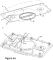
- FIG. 4a shows two corresponding views of a second embodiment of a sensor unit 1 consistent with the principles of the invention.
- This embodiment has many of the same features as the embodiment discussed with reference to FIG. 3 , including a strain gauge 3, a substrate 4', a screw 5 which passes through the substrate 4' and a flexible ring 7 and is screwed into a snap on button 8.
- This embodiment also includes a front part 9 and a back part 10 of a casing and a battery holder 11, as well as necessary room for additional electronic circuitry (not shown).
- the substrate 4' in this embodiment is made from a metal alloy, for example steel.
- the substrate 4' is attached to the back part 10 of the casing, for example by being held inside a narrow gap between two protrusions 13, although other alternatives are possible, for example by gluing or using screws.
- the substrate 4' is configured such that when a force is applied to the substrate 4' from the belt 2 ( FIG. 1 ) through the snap button 8 and the screw 5, the part of the substrate 4' to which the strain gauge 3 is attached will bend.
- Several configurations of the substrate 4' may provide this functionality.
- the strain gauge is attached to a surface of a first portion of the substrate 4' that is normal to the direction of the force transmitted from the belt 2, while the screw 5 passes through a second portion of the substrate 4' with a surface that is parallel to the direction of the applied force and attached to the first portion at the opposite end from the end that is attached to the back part 10 of the casing.
- only one snap on button 8 is configured to transmit force to the substrate 4'.
- the snap on button and screw that only serve to provide attachment to the belt 2 are without reference numbers in order to avoid confusion an unnecessary clutter in the drawing.
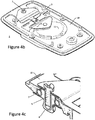
- FIG. 4b is a view of an alternative configuration of the second embodiment.
- one end of the substrate 4' is attached to the back part of the casing 10, for instance to the top of the room for the battery 11.
- the other end is attached with the screw 5 just like in the first configuration.
- the substrate 4' is substantially straight and flat between the to attachment points, but may be curved relative to its own plane such that when it is subject to stretching forces the corved sections will straighten.
- a strain gauge 3 may be attached to a section of the substrate that is particularly subject to deformation by stretching forces transmitted from the belt.
- FIG. 4c is a detail view of the end of the substrate 4' which is attached to the screw 5 and snap on button 8.
- the screw enters the snap on button 8 which is mounted in a flexible ring 7.
- the flexible ring 7 holds the snap on button 8 while at the same time allowing it to move relatively to the back part of the casing 10.
- the flexible ring 7, which may be an o-ring, also serves as a watertight seal which prevents water from entering the device 1. This design can be adapted to all the embodiments described herein where the substrate is attached to the fastening mechanism and not to the casing.
- screw 5 may be replaced with some other fastening device, for instance a metal post which passes through the substrate and into the snap button where it is riveted.
- some other fastening device for instance a metal post which passes through the substrate and into the snap button where it is riveted.
- Other alternatives include gluing and plastic welding.
- FIG. 5 is an illustration of yet another embodiment of the invention, in which the strain gauge 3 is mounted on a polymer substrate 4" mounted between two layers of the belt 2.
- the substrate 4" is attached to two snap on buttons 14 which are configured to mate with corresponding snap on buttons on a device holding electronic circuitry, battery and other components.
- the electronic device is not shown, but may be shaped in the same manner as the sensor units 1 illustrated in FIG. 3 and FIG. 4 , but without the components that have been moved to the belt 2.
- One or both of the snap on buttons on the device corresponding to snap on buttons 8 must be free to move sufficiently so they do not prevent the relative movement of the snap on buttons 14 with respect to each other, such that force can be transmitted to the substrate 4". This may be achieved by use of one or two flexible rings corresponding to flexible rings 7 in FIG. 3 and FIG. 4 .
- the substrate is provided between two snap on buttons. This may require that the sensor unit provides sufficient flexibility to allow the stretching forces in the belt to deform the substrate 4".
- An alternative is to provide the substrate 4" and the strain gauge 3 in a different part of the belt 2. This is possible provided that the opposite ends of the substrate is attached to the layers of the belt in a manner that transmits tensile forces in a consistent manner.
- the strain gauge 3 may still be electrically connected to the snap on buttons 8 for transmission of signals to the electronic circuitry in the sensor unit 1. Any other sensors provided in the belt 2, such as heart rate measurement electrodes, may transfer signals in the same manner through the snap on buttons 8.
- the strain gauge 3 measures deformation of the substrate 4, 4', 4"
- this deformation depends on the elasticity, dimensions and shape of the material from which the substrade is made and the amount of force transmitted to the substrate 4, 4', 4" from the belt 2, which again depends on the elasticity of the belt. Consequently, the belt and the substrate, as well as the parts that transmit force from the one to the other, must be designed to work well with each other. On the one hand it is desirable make the belt as flexible as possible in order to increas comfort for the person wearing the belt. On the other hand the belt must transmit sufficient force to the substrate to cause the desired deformation.
- the belt can be almost entirely without flexibility, provided that the substrate and other mechanisms in the sensor unit 1 is able to stretch sufficiently.
- the belt is at least somewhat flexible, but a belt without elasticity combined with a sensor unit providing the necessary elasticity instead is within the scope of the invention.
- the combination belt and sensor unit should be capable of expanding approximately 2 to 3 cm during use.
- Flow t ⁇ V ⁇ t
- A is the area defined by the circumference (assumed to be circular)
- O is the circumference
- r the radius
- V the volume.
- O start 0.83m
- k 1 300
- 1/k 1 0.003
- Fmax 6.2 N
- Fmin 3.0 N
- ⁇ t 1.5
- O start is the circumference of the belt when it is adjusted to fit the wearer, but not actually worn (i.e.
- O max is the maximum circumference i.e. when the maximum force, F max is measured by the sensor
- O min is the minimum circumference i.e. when the minimum force, F min is measured by the sensor.
- O start will depend on the adjustment of the belt made by the user, and the device may allow for individual calibration by entering this value for example over a Bluetooth interface. However, in some embodiments of the invention, the belt may not allow adjustment and operate with a fixed circumference which is known in advance, or only a minimum of adjustment may be possible and the margin of error introduced by this adjustment may be considered acceptable.
- the flow calculated here as 0.27 l/s is the rate at which air flows into the lungs during inhalation. To determine air intake over time, i.e. ventilation, this value must be multiplied with the ratio ⁇ t / Bp.
- the electronic circuitry of the sensor unit 1 includes a controller which is capable of sampling the output of the strain gauge with a sampling rate at least twice the maximum breathing rate (or, since inhalation time is typically shorter than exhalation time, a frequency that is at least 1/ ⁇ t min ), where ⁇ t min is the shortest expected inhalation time.
- Respiratory rate during exercise will typically reach a level of approximately 30 breaths per minute, but may go significantly higher at high levels of exhaustion, and may reach levels as high as 60 breaths per minute or more, which translates to a sampling rate of at least 2Hz.
- the breathing signal delivered from the strain gauge may include higher frequency components and in some embodiments of the invention the signal form the strain gauge is filtered with a low pass filter at somewhere in the range of 7-10 Hz, which requires a sampling rate of 14-20 Hz. It may, however, be desirable to track the signal more closely in order to simplify the algorithms used to detect the maximum and minimum values. For this purpose a sampling rate of 100 Hz has been found suitable. On the other hand, higher sampling frequency increases power consumption in the sensor unit and it may therefore be desirable to reduce the number of samples.
- low power electronics detect the minimum and maximum values of the signal and send an interrupt to the controller, which may be a microprocessor or CPU, such that the controller operates at high power only near the maximum and minimum values of the signal and revert to a low power mode in between.
- the controller which may be a microprocessor or CPU, such that the controller operates at high power only near the maximum and minimum values of the signal and revert to a low power mode in between.
- Sampling rate is consequently a design parameter that must be chosen based on the range of respiratory rates the device should be able to measure.
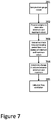
- FIG. 7 illustrates in a flow chart a method of calculating ventilation based on measurements performed with a device consistent with the principles of the invention. It should be understood that this flowchart by necessity have to show the steps in sequence, but that some of the steps may be performed in a different sequence or simultaneously. Equally well, some steps may be performed in the sensor unit while other steps are performed in a receiving unit. Some steps may even be performed partially in the receiver unit in order to reduce the amount of data that is transmitted to the receiving unit, for example in order to conserve power used for transmission, and the calculations may then be completed in the receiving unit. Additional steps such as filtering, may also be performed.
- a first step 701 the output form the strain gauge 3 sampled in order to produce a digital signal that can be processed further.
- Sampling rate has been discussed above, and the number of bits per sample may be 12, although other alternatives, such as 8, 10 or 16 bits/sample, are within the scope of the invention.
- step 702 the samples are processed in order to detect minimum and maximum values. This may be performed using derivation, using mathematical methods that are well known in the art.
- step 703 Based on the detection of maximum and minimum values, significant points in time may be detected in step 703 and the inhalation time ⁇ t and breathing period Bp may be determined. The values produced by these calculations may then be used in step 704 to determine an estimate of change in lung volume during inhalation, ⁇ V. From this result, further refinements may be calculated in step 705, such as flow during inhalation, total ventilation (e.g. expressed as liters/minute), oxygen uptake VO 2 , ventilation threshold, lactate threshold etc.
- flow during inhalation e.g. expressed as liters/minute
- oxygen uptake VO 2 e.g. expressed as liters/minute
- ventilation threshold e.g. expressed as liters/minute
- FIG. 8 is a drawing depicting a block diagram of the most important modules of the electronic circuitry of devices operating according to the invention.
- the drawing includes two main units, a sensor unit 801 and a computing device 850.
- the sensor unit 801 includes a strain gauge 803 connected to a Wheatstone bridge 820.
- the Wheatstone bride 820 is connected to an amplifier 822 which delivers a signal to an analog-to-digital converter 824.
- the digital signal is sampled by a controller 826 which may be a microprocessor.
- the controller may operate in accordance with instructions stored in local memory 828, although other hardware/software combinations are possible, as discussed above.
- the controller and the memory 828 may communicate over a signal bus which is also connected to a wireless unit 830, which may for example be a Bluetooth device.
- the wireless unit 830 is able to establish a communication link with a corresponding wireless unit 852 in computing unit 850.
- the computing unit 850 includes another microprocessor 854 and local memory 856, all communicating over a bus.
- the computing unit may also include a display device 858 as well as other user interface components (not shown) such as a loudspeaker, input buttons, a keyboard, a touch interface etc.
- the calculations are performed in the sensor unit 1.
- the electronic circuitry of the sensor unit 1 may include a microprocessor, a microcontroller, an ASIC or some other type of system-on-chip (SoC), for example a field-programmable gate array (FPGA) capable of performing the necessary calculations.
- SoC system-on-chip
- FPGA field-programmable gate array
- the sensor unit may include such circuitry even if these calculations are performed external to the sensor unit 1.
- the sensor unit 1 must at least include sufficient circuitry to perform analog/digital conversion and the capability of transmitting samples in a manner that preserves sufficient information regarding both measured force and time to enable the receiving device to perform the calculations described above.
- the sensor unit 1 may be configured to transmit raw measurement data to an external device which is configured to perform the calculations.
- the sensor unit 1 may be capable of transmitting data to a device worn by the person wearing the sensor unit 1 and the belt 2.
- This device may be substantially similar to devices known in the art for receiving HRM data, and indeed the device may include some or all of the capabilities of such a HRM device, just as the sensor unit 1 and the belt 2 may include HRM capabilities in combination with the features provided by the invention.
- the sensor unit 1 may be configured to simply store date during exercise and allow the data to be downloaded for example to a computer after the exercise has been completed.
- the method described above may, according to the invention, be embodied in a computer program product which is stored in a computer readable memory or installed in a device which is capable of receiving data from the sensor unit 1 for example using a Bluetooth link.
- a device may be a wearable device which is capable of performing the calculations in real time and display the results on a display or produce audible signals indicating operation within or outside a desirable range.
- the device may be a general purpose computer such as a PC which is capable of downloading the data after an exercise is completed and perform calculations and present results to the user at that time.
- the strain gauge may be a semiconductor strain gauge, but other alternatives include the foil gauge type, the piezoresistor type or any other type of strain gauge known in the art. Other details may also vary from the examples used in this description.
- the snap on buttons may be replaced by other fastening devices known in the art.
- the sensor unit may be an integrated part of the belt, and not detachable.
- the belt may be part of a larger harness such as a sports bra, an elastic shirt or some other wearable device which transmits force as a function of expansion of the chest of a wearer while breathing.
- the term belt should be understood as any garment which encircles the chest or stomach of the wearer, even if the actual belt shape is integrated into another garment.
- the invention may also be adapted to other large mammals, such as a racing horse or a racing dog, and the belt may be worn around a part of the torso of the subject that expands and contracts as a function of the subject's breathing, which in most cases means the chest and part of the stomach.
- the force is transmitted from the belt to the substrate by way of the mechanism including a snap on button 8, a screw 5 and, with respect to FIG. 3 , a protective plate 6, and the mechanism is coupled to the casing with a flexible ring 7.
- the mechanism including a snap on button 8, a screw 5 and, with respect to FIG. 3 , a protective plate 6, and the mechanism is coupled to the casing with a flexible ring 7.
- Other alternatives are possible within the scope of the invention, including permanent attachment to the belt by glue, molded plastic, or sewing, and with a flexible attachment to the casing of the sensor device using plastic or metal parts that are free to slide relatively to each other, that include springs or other flexible material such as foam rubber.
Landscapes
- Health & Medical Sciences (AREA)
- Life Sciences & Earth Sciences (AREA)
- Engineering & Computer Science (AREA)
- Physics & Mathematics (AREA)
- General Health & Medical Sciences (AREA)
- Molecular Biology (AREA)
- Veterinary Medicine (AREA)
- Public Health (AREA)
- Animal Behavior & Ethology (AREA)
- Surgery (AREA)
- Biophysics (AREA)
- Pathology (AREA)
- Biomedical Technology (AREA)
- Heart & Thoracic Surgery (AREA)
- Medical Informatics (AREA)
- Physiology (AREA)
- Pulmonology (AREA)
- Dentistry (AREA)
- Oral & Maxillofacial Surgery (AREA)
- Computer Vision & Pattern Recognition (AREA)
- Artificial Intelligence (AREA)
- Signal Processing (AREA)
- General Physics & Mathematics (AREA)
- Psychiatry (AREA)
- Computer Networks & Wireless Communication (AREA)
- Measurement Of The Respiration, Hearing Ability, Form, And Blood Characteristics Of Living Organisms (AREA)
- Measuring Pulse, Heart Rate, Blood Pressure Or Blood Flow (AREA)
Claims (8)
- Atmungsmessvorrichtung umfassend:einen Befestigungsmechanismus (8), der die Atmungsmessvorrichtung (1) an einem Gurt (2) permanent oder abnehmbar befestigen kann, der um einen Teil des Rumps eines Individuums getragen werden kann, welcher sich als eine Funktion der Einatmung aufweitet;ein Substrat (4, 4', 4"), das mit dem Befestigungsmechanismus (8) verbunden ist und Zugkräfte aufnehmen kann, die vom Gurt (2) durch den Befestigungsmechanismus (8) übertragen werden;ein Dehnungsmessgerät (3), das auf dem Substrat montiert ist und dafür ausgelegt ist, ein Signal mit einem Funktionsverhältnis mit den Zugkräften auszugeben;eine Steuereinheit, die dafür ausgelegt ist, das Signal zu empfangen und zu behandeln und daraus behandelte Daten zu erzeugen; undeinen Sender, der dafür ausgelegt ist, durch die Steuereinheit gesteuert zu werden, um behandelte Daten an einen externen Empfänger zu übertragen;dadurch gekennzeichnet, dass sie weiter ein Gehäuse (10) umfasst; und wobeider Befestigungsmechanismus (8) zwei Teile enthält, wovon der erste an einem ersten Ende des Substrats (4) direkt befestigt ist und der zweite entweder- direkt am zweiten Ende des Substrats (4) befestigt ist, um Zugkräfte direkt an das Substrat (4) zu übertragen, oder- direkt am Gehäuse (10) befestigt ist, um Zugkräfte an ein anderes Ende des Substrats (4) zu übertragen, wobei das zweite Ende des Substrats (4) direkt am Gehäuse (10) befestigt ist; unddie Befestigung des ersten Teils des Befestigungsmechanismus (8) durch einen flexiblen Ring (7) durchgeht, der den Befestigungsmechanismus mit dem Gehäuse (10) verbindet, während der erste Teil des Befestigungsmechanismus sich im Verhältnis zum Gehäuse (10) bewegen kann, um Zugkräfte an das Substrat (4) zu übertragen.
- Atmungsmessvorrichtung nach Anspruch 1, wobei:die zwei Teile des Befestigungsmechanismus (8) an jeweiligen Enden des Substrats (4) und an jeweiligen Punkten des Gurts (2) befestigt sind; unddas Substrat (4) aus einem Polymer hergestellt ist und Zugkräften ausgesetzt wird, die vom Gurt (2) als eine Funktion einer Streckung des Gurts übertragen werden.
- Atmungsmessvorrichtung nach Anspruch 2, weiter umfassend:eine Schutzplatte (6) an zumindest einem Ende des Substrats (4), die dafür ausgelegt ist, die Bewegung in eine Richtung einzuschränken und eine Drehbewegung zu verhindern; und wobeidie Befestigung des Befestigungsmechanismus (8) am Substrat (4) am zumindest einen Ende des Substrats (4) eine Schraube (5) umfasst, die durch die Schutzplatte (6) durch den flexiblen Ring (7), der die Schraube mit dem Gehäuse (10) verbindet, durchgeht und in den Befestigungsmechanismus (8) hineingeht.
- Atmungsmessvorrichtung nach Anspruch 1, wobei:der Befestigungsmechanismus einen ersten Teil, der an einem Ende des Substrats (4') befestigt ist, und einen zweiten Teil, der am Gehäuse (10) der Atmungsmessvorrichtung (1) befestigt ist, umfasst; unddas Substrat (4') aus einem Metall hergestellt ist, am Gehäuse (10) an einem Ende befestigt ist, das am ersten Teil des Befestigungsmechanismus (8) nicht befestigt ist, und so ausgelegt ist, dass das Dehnungsmessgerät (3) Zug- oder Kompressionskräften ausgesetzt wird, wenn Zugkräfte vom Gurt (2) an das Substrat (4') übertragen werden.
- Atmungsmessvorrichtung nach Anspruch 4, wobei:
die Befestigung des ersten Teils des Befestigungsmechanismus (8) an einem Ende des Substrats (4') eine Schraube (5) umfasst, die durch den flexiblen Ring (7), der die Schraube mit dem Gehäuse (10) verbindet, durchgeht und in den Befestigungsmechanismus (8) hineingeht. - Atmungsmessvorrichtung nach einem der vorgehenden Ansprüche, wobei die Steuereinheit ein Mikroprozessor ist.
- Atmungsmessvorrichtung nach Anspruch 6, wobei der Mikroprozessor dafür ausgelegt ist, Signale abzutasten, die vom Dehnungsmessgerät (3) empfangen werden; und
den Sender dazu zu steuern, Daten mit einem Funktionsverhältnis mit Zugkräften im Gurt (2) zu übertragen. - Atmungsmessvorrichtung nach einem der vorgehenden Ansprüche, weiter umfassend:einen Mikroprozessor;eine Sende-Empfangsvorrichtung, die mit dem Mikroprozessor verbunden ist;eine Lagerungseinheit, die Anweisungen und Daten aufbewahren kann; undeine Anzeigeeinheit; wobeidie Lagerungseinheit Anweisungen enthält, die bewirken, dass der MikroprozessorDatenproben empfängt, die Zugkräfte im Gurt (2) darstellen;Maximum- und Minimumwerte aus den empfangenen Datenproben festlegt;Einatmungszeit und Atmungszeitraum aus dem zeitlichen Verhältnis der Datenproben festlegt;eine geschätzte Änderung des Lungenvolumens während der Einatmung basierend auf den Maximum- und Minimumwerten berechnet;mindestens eine von einer geschätzten Strömung während der Einatmung, einer geschätzten Atmungsrate, einer geschätzten Sauerstoffaufnahme und einer Atmungsschwelle für die Person, die den Gurt (2) trägt, berechnet; und Information, die die Berechnungen auf der Anzeigeeinheit darstellt, anzeigt.
Applications Claiming Priority (3)
| Application Number | Priority Date | Filing Date | Title |
|---|---|---|---|
| NO20150351 | 2015-03-20 | ||
| NO20150372A NO346802B1 (en) | 2015-03-20 | 2015-03-24 | Ventilation measurement devices and computer program product |
| PCT/NO2016/050054 WO2016153358A2 (en) | 2015-03-20 | 2016-03-18 | Ventilation measurement devices, methods and computer program product |
Publications (2)
| Publication Number | Publication Date |
|---|---|
| EP3270782A2 EP3270782A2 (de) | 2018-01-24 |
| EP3270782B1 true EP3270782B1 (de) | 2021-03-10 |
Family
ID=56134529
Family Applications (1)
| Application Number | Title | Priority Date | Filing Date |
|---|---|---|---|
| EP16730032.6A Active EP3270782B1 (de) | 2015-03-20 | 2016-03-18 | Atmungsmessvorrichtungen |
Country Status (3)
| Country | Link |
|---|---|
| US (1) | US10595779B2 (de) |
| EP (1) | EP3270782B1 (de) |
| WO (1) | WO2016153358A2 (de) |
Families Citing this family (3)
| Publication number | Priority date | Publication date | Assignee | Title |
|---|---|---|---|---|
| US20230018531A1 (en) * | 2021-07-09 | 2023-01-19 | Stream DX, Inc | Uroflow measurement device implementing load cell based weight measurement using rigid support passing through spacer within flexible diaphragm of housing |
| CN114287926A (zh) * | 2021-12-28 | 2022-04-08 | 深圳融昕医疗科技有限公司 | 监测人体呼吸和胸腹运动的装置 |
| US12457443B2 (en) * | 2023-03-31 | 2025-10-28 | Merry Electronics (Shenzhen) Co., Ltd. | Headset device and control method thereof |
Family Cites Families (9)
| Publication number | Priority date | Publication date | Assignee | Title |
|---|---|---|---|---|
| FR2353268A1 (fr) | 1976-06-02 | 1977-12-30 | Keczely Lajos | Capteur de respiration |
| US4960118A (en) | 1989-05-01 | 1990-10-02 | Pennock Bernard E | Method and apparatus for measuring respiratory flow |
| US5454376A (en) | 1993-08-16 | 1995-10-03 | Stephens; David L. | Breathing monitor articles of wearing apparel |
| US20090131759A1 (en) | 2003-11-04 | 2009-05-21 | Nathaniel Sims | Life sign detection and health state assessment system |
| US20070299325A1 (en) * | 2004-08-20 | 2007-12-27 | Brian Farrell | Physiological status monitoring system |
| US7942824B1 (en) | 2005-11-04 | 2011-05-17 | Cleveland Medical Devices Inc. | Integrated sleep diagnostic and therapeutic system and method |
| US9028404B2 (en) | 2010-07-28 | 2015-05-12 | Foster-Miller, Inc. | Physiological status monitoring system |
| JP2014096220A (ja) * | 2012-11-07 | 2014-05-22 | Seiko Instruments Inc | 電子機器 |
| JP6132603B2 (ja) * | 2013-03-12 | 2017-05-24 | セイコーインスツル株式会社 | 携帯型電子機器 |
-
2016
- 2016-03-18 EP EP16730032.6A patent/EP3270782B1/de active Active
- 2016-03-18 WO PCT/NO2016/050054 patent/WO2016153358A2/en not_active Ceased
- 2016-03-18 US US15/560,073 patent/US10595779B2/en active Active
Non-Patent Citations (1)
| Title |
|---|
| None * |
Also Published As
| Publication number | Publication date |
|---|---|
| EP3270782A2 (de) | 2018-01-24 |
| WO2016153358A3 (en) | 2016-12-01 |
| WO2016153358A2 (en) | 2016-09-29 |
| US10595779B2 (en) | 2020-03-24 |
| US20180078208A1 (en) | 2018-03-22 |
Similar Documents
| Publication | Publication Date | Title |
|---|---|---|
| US11172850B2 (en) | System and method to monitor, guide, and evaluate breathing, utilizing posture and diaphragm sensor signals | |
| US7108659B2 (en) | Respiratory analyzer for exercise use | |
| US20140073970A1 (en) | Physiological Condition Monitor | |
| US20220087575A1 (en) | System and method to monitor, guide, and evaluate breathing | |
| CN109937000A (zh) | 便携式肺活量计 | |
| US12138037B2 (en) | Device, system, and method for assessing sleep disorders | |
| TWI535414B (zh) | 訊號量測方法及相關穿戴式電子裝置 | |
| US20210076980A1 (en) | Portable handheld electronic spirometer | |
| KR20060019869A (ko) | 필름형 압박 센서를 통한 운동량 측정 장치 및 그 방법 | |
| JP2007296266A (ja) | 生体センサ装置 | |
| WO2016142666A1 (en) | Monitoring vital signs | |
| EP3212082B1 (de) | Mundvorrichtung für beatmungsflussmessung | |
| EP3270782B1 (de) | Atmungsmessvorrichtungen | |
| WO2014171547A1 (ja) | 歩行試験装置 | |
| JP2018007979A (ja) | 運動支援装置及び運動支援方法、運動支援プログラム | |
| KR102202015B1 (ko) | 생체 신호 측정 장치 | |
| JP6566047B2 (ja) | 体温計 | |
| CN107205672B (zh) | 用于评估监测对象的呼吸数据的装置和方法 | |
| CN113769342B (zh) | 腹式呼吸训练带及穿戴式治疗仪 | |
| US20230084864A1 (en) | Method And Device That Generates A Respiration Signal | |
| NO20150372A1 (en) | Ventilation measurement devices and computer program product | |
| CN108523845A (zh) | 便携式新陈代谢测量仪 | |
| KR102129488B1 (ko) | 자세 교정이 가능한 헬스 케어 기기 | |
| RU2401062C1 (ru) | Портативная телеметрическая система регистрации параметров внешнего дыхания спортсмена в реальном времени и дыхательная трубка пловца для ее осуществления | |
| US20230405374A1 (en) | Methods, apparatuses, and systems for evaluating respiratory protective devices |
Legal Events
| Date | Code | Title | Description |
|---|---|---|---|
| STAA | Information on the status of an ep patent application or granted ep patent |
Free format text: STATUS: THE INTERNATIONAL PUBLICATION HAS BEEN MADE |
|
| PUAI | Public reference made under article 153(3) epc to a published international application that has entered the european phase |
Free format text: ORIGINAL CODE: 0009012 |
|
| STAA | Information on the status of an ep patent application or granted ep patent |
Free format text: STATUS: REQUEST FOR EXAMINATION WAS MADE |
|
| 17P | Request for examination filed |
Effective date: 20171018 |
|
| AK | Designated contracting states |
Kind code of ref document: A2 Designated state(s): AL AT BE BG CH CY CZ DE DK EE ES FI FR GB GR HR HU IE IS IT LI LT LU LV MC MK MT NL NO PL PT RO RS SE SI SK SM TR |
|
| AX | Request for extension of the european patent |
Extension state: BA ME |
|
| DAV | Request for validation of the european patent (deleted) | ||
| DAX | Request for extension of the european patent (deleted) | ||
| GRAP | Despatch of communication of intention to grant a patent |
Free format text: ORIGINAL CODE: EPIDOSNIGR1 |
|
| STAA | Information on the status of an ep patent application or granted ep patent |
Free format text: STATUS: GRANT OF PATENT IS INTENDED |
|
| INTG | Intention to grant announced |
Effective date: 20201009 |
|
| GRAS | Grant fee paid |
Free format text: ORIGINAL CODE: EPIDOSNIGR3 |
|
| GRAA | (expected) grant |
Free format text: ORIGINAL CODE: 0009210 |
|
| STAA | Information on the status of an ep patent application or granted ep patent |
Free format text: STATUS: THE PATENT HAS BEEN GRANTED |
|
| AK | Designated contracting states |
Kind code of ref document: B1 Designated state(s): AL AT BE BG CH CY CZ DE DK EE ES FI FR GB GR HR HU IE IS IT LI LT LU LV MC MK MT NL NO PL PT RO RS SE SI SK SM TR |
|
| REG | Reference to a national code |
Ref country code: GB Ref legal event code: FG4D |
|
| REG | Reference to a national code |
Ref country code: AT Ref legal event code: REF Ref document number: 1368881 Country of ref document: AT Kind code of ref document: T Effective date: 20210315 Ref country code: CH Ref legal event code: EP |
|
| REG | Reference to a national code |
Ref country code: DE Ref legal event code: R096 Ref document number: 602016053992 Country of ref document: DE |
|
| REG | Reference to a national code |
Ref country code: IE Ref legal event code: FG4D |
|
| REG | Reference to a national code |
Ref country code: LT Ref legal event code: MG9D |
|
| PG25 | Lapsed in a contracting state [announced via postgrant information from national office to epo] |
Ref country code: GR Free format text: LAPSE BECAUSE OF FAILURE TO SUBMIT A TRANSLATION OF THE DESCRIPTION OR TO PAY THE FEE WITHIN THE PRESCRIBED TIME-LIMIT Effective date: 20210611 Ref country code: HR Free format text: LAPSE BECAUSE OF FAILURE TO SUBMIT A TRANSLATION OF THE DESCRIPTION OR TO PAY THE FEE WITHIN THE PRESCRIBED TIME-LIMIT Effective date: 20210310 Ref country code: FI Free format text: LAPSE BECAUSE OF FAILURE TO SUBMIT A TRANSLATION OF THE DESCRIPTION OR TO PAY THE FEE WITHIN THE PRESCRIBED TIME-LIMIT Effective date: 20210310 Ref country code: NO Free format text: LAPSE BECAUSE OF FAILURE TO SUBMIT A TRANSLATION OF THE DESCRIPTION OR TO PAY THE FEE WITHIN THE PRESCRIBED TIME-LIMIT Effective date: 20210610 Ref country code: LT Free format text: LAPSE BECAUSE OF FAILURE TO SUBMIT A TRANSLATION OF THE DESCRIPTION OR TO PAY THE FEE WITHIN THE PRESCRIBED TIME-LIMIT Effective date: 20210310 Ref country code: BG Free format text: LAPSE BECAUSE OF FAILURE TO SUBMIT A TRANSLATION OF THE DESCRIPTION OR TO PAY THE FEE WITHIN THE PRESCRIBED TIME-LIMIT Effective date: 20210610 |
|
| REG | Reference to a national code |
Ref country code: AT Ref legal event code: MK05 Ref document number: 1368881 Country of ref document: AT Kind code of ref document: T Effective date: 20210310 |
|
| REG | Reference to a national code |
Ref country code: NL Ref legal event code: MP Effective date: 20210310 |
|
| PG25 | Lapsed in a contracting state [announced via postgrant information from national office to epo] |
Ref country code: SE Free format text: LAPSE BECAUSE OF FAILURE TO SUBMIT A TRANSLATION OF THE DESCRIPTION OR TO PAY THE FEE WITHIN THE PRESCRIBED TIME-LIMIT Effective date: 20210310 Ref country code: RS Free format text: LAPSE BECAUSE OF FAILURE TO SUBMIT A TRANSLATION OF THE DESCRIPTION OR TO PAY THE FEE WITHIN THE PRESCRIBED TIME-LIMIT Effective date: 20210310 Ref country code: LV Free format text: LAPSE BECAUSE OF FAILURE TO SUBMIT A TRANSLATION OF THE DESCRIPTION OR TO PAY THE FEE WITHIN THE PRESCRIBED TIME-LIMIT Effective date: 20210310 |
|
| PG25 | Lapsed in a contracting state [announced via postgrant information from national office to epo] |
Ref country code: NL Free format text: LAPSE BECAUSE OF FAILURE TO SUBMIT A TRANSLATION OF THE DESCRIPTION OR TO PAY THE FEE WITHIN THE PRESCRIBED TIME-LIMIT Effective date: 20210310 |
|
| PG25 | Lapsed in a contracting state [announced via postgrant information from national office to epo] |
Ref country code: EE Free format text: LAPSE BECAUSE OF FAILURE TO SUBMIT A TRANSLATION OF THE DESCRIPTION OR TO PAY THE FEE WITHIN THE PRESCRIBED TIME-LIMIT Effective date: 20210310 Ref country code: CZ Free format text: LAPSE BECAUSE OF FAILURE TO SUBMIT A TRANSLATION OF THE DESCRIPTION OR TO PAY THE FEE WITHIN THE PRESCRIBED TIME-LIMIT Effective date: 20210310 Ref country code: SM Free format text: LAPSE BECAUSE OF FAILURE TO SUBMIT A TRANSLATION OF THE DESCRIPTION OR TO PAY THE FEE WITHIN THE PRESCRIBED TIME-LIMIT Effective date: 20210310 Ref country code: AT Free format text: LAPSE BECAUSE OF FAILURE TO SUBMIT A TRANSLATION OF THE DESCRIPTION OR TO PAY THE FEE WITHIN THE PRESCRIBED TIME-LIMIT Effective date: 20210310 |
|
| REG | Reference to a national code |
Ref country code: CH Ref legal event code: PL |
|
| PG25 | Lapsed in a contracting state [announced via postgrant information from national office to epo] |
Ref country code: IS Free format text: LAPSE BECAUSE OF FAILURE TO SUBMIT A TRANSLATION OF THE DESCRIPTION OR TO PAY THE FEE WITHIN THE PRESCRIBED TIME-LIMIT Effective date: 20210710 Ref country code: PL Free format text: LAPSE BECAUSE OF FAILURE TO SUBMIT A TRANSLATION OF THE DESCRIPTION OR TO PAY THE FEE WITHIN THE PRESCRIBED TIME-LIMIT Effective date: 20210310 Ref country code: PT Free format text: LAPSE BECAUSE OF FAILURE TO SUBMIT A TRANSLATION OF THE DESCRIPTION OR TO PAY THE FEE WITHIN THE PRESCRIBED TIME-LIMIT Effective date: 20210712 Ref country code: SK Free format text: LAPSE BECAUSE OF FAILURE TO SUBMIT A TRANSLATION OF THE DESCRIPTION OR TO PAY THE FEE WITHIN THE PRESCRIBED TIME-LIMIT Effective date: 20210310 Ref country code: RO Free format text: LAPSE BECAUSE OF FAILURE TO SUBMIT A TRANSLATION OF THE DESCRIPTION OR TO PAY THE FEE WITHIN THE PRESCRIBED TIME-LIMIT Effective date: 20210310 |
|
| REG | Reference to a national code |
Ref country code: DE Ref legal event code: R097 Ref document number: 602016053992 Country of ref document: DE |
|
| REG | Reference to a national code |
Ref country code: BE Ref legal event code: MM Effective date: 20210331 |
|
| PLBE | No opposition filed within time limit |
Free format text: ORIGINAL CODE: 0009261 |
|
| STAA | Information on the status of an ep patent application or granted ep patent |
Free format text: STATUS: NO OPPOSITION FILED WITHIN TIME LIMIT |
|
| PG25 | Lapsed in a contracting state [announced via postgrant information from national office to epo] |
Ref country code: DK Free format text: LAPSE BECAUSE OF FAILURE TO SUBMIT A TRANSLATION OF THE DESCRIPTION OR TO PAY THE FEE WITHIN THE PRESCRIBED TIME-LIMIT Effective date: 20210310 Ref country code: IE Free format text: LAPSE BECAUSE OF NON-PAYMENT OF DUE FEES Effective date: 20210318 Ref country code: ES Free format text: LAPSE BECAUSE OF FAILURE TO SUBMIT A TRANSLATION OF THE DESCRIPTION OR TO PAY THE FEE WITHIN THE PRESCRIBED TIME-LIMIT Effective date: 20210310 Ref country code: AL Free format text: LAPSE BECAUSE OF FAILURE TO SUBMIT A TRANSLATION OF THE DESCRIPTION OR TO PAY THE FEE WITHIN THE PRESCRIBED TIME-LIMIT Effective date: 20210310 Ref country code: CH Free format text: LAPSE BECAUSE OF NON-PAYMENT OF DUE FEES Effective date: 20210331 Ref country code: LI Free format text: LAPSE BECAUSE OF NON-PAYMENT OF DUE FEES Effective date: 20210331 Ref country code: MC Free format text: LAPSE BECAUSE OF FAILURE TO SUBMIT A TRANSLATION OF THE DESCRIPTION OR TO PAY THE FEE WITHIN THE PRESCRIBED TIME-LIMIT Effective date: 20210310 Ref country code: LU Free format text: LAPSE BECAUSE OF NON-PAYMENT OF DUE FEES Effective date: 20210318 |
|
| 26N | No opposition filed |
Effective date: 20211213 |
|
| PLAA | Information modified related to event that no opposition was filed |
Free format text: ORIGINAL CODE: 0009299DELT |
|
| PLBE | No opposition filed within time limit |
Free format text: ORIGINAL CODE: 0009261 |
|
| GBPC | Gb: european patent ceased through non-payment of renewal fee |
Effective date: 20210610 |
|
| PG25 | Lapsed in a contracting state [announced via postgrant information from national office to epo] |
Ref country code: SI Free format text: LAPSE BECAUSE OF FAILURE TO SUBMIT A TRANSLATION OF THE DESCRIPTION OR TO PAY THE FEE WITHIN THE PRESCRIBED TIME-LIMIT Effective date: 20210310 |
|
| R26N | No opposition filed (corrected) |
Effective date: 20211213 |
|
| RAP2 | Party data changed (patent owner data changed or rights of a patent transferred) |
Owner name: VIMSCORE AS |
|
| PG25 | Lapsed in a contracting state [announced via postgrant information from national office to epo] |
Ref country code: IT Free format text: LAPSE BECAUSE OF FAILURE TO SUBMIT A TRANSLATION OF THE DESCRIPTION OR TO PAY THE FEE WITHIN THE PRESCRIBED TIME-LIMIT Effective date: 20210310 Ref country code: GB Free format text: LAPSE BECAUSE OF NON-PAYMENT OF DUE FEES Effective date: 20210610 |
|
| PG25 | Lapsed in a contracting state [announced via postgrant information from national office to epo] |
Ref country code: IS Free format text: LAPSE BECAUSE OF FAILURE TO SUBMIT A TRANSLATION OF THE DESCRIPTION OR TO PAY THE FEE WITHIN THE PRESCRIBED TIME-LIMIT Effective date: 20210710 Ref country code: FR Free format text: LAPSE BECAUSE OF NON-PAYMENT OF DUE FEES Effective date: 20210510 |
|
| PG25 | Lapsed in a contracting state [announced via postgrant information from national office to epo] |
Ref country code: BE Free format text: LAPSE BECAUSE OF NON-PAYMENT OF DUE FEES Effective date: 20210331 |
|
| PG25 | Lapsed in a contracting state [announced via postgrant information from national office to epo] |
Ref country code: CY Free format text: LAPSE BECAUSE OF FAILURE TO SUBMIT A TRANSLATION OF THE DESCRIPTION OR TO PAY THE FEE WITHIN THE PRESCRIBED TIME-LIMIT Effective date: 20210310 |
|
| PG25 | Lapsed in a contracting state [announced via postgrant information from national office to epo] |
Ref country code: HU Free format text: LAPSE BECAUSE OF FAILURE TO SUBMIT A TRANSLATION OF THE DESCRIPTION OR TO PAY THE FEE WITHIN THE PRESCRIBED TIME-LIMIT; INVALID AB INITIO Effective date: 20160318 |
|
| PG25 | Lapsed in a contracting state [announced via postgrant information from national office to epo] |
Ref country code: MK Free format text: LAPSE BECAUSE OF FAILURE TO SUBMIT A TRANSLATION OF THE DESCRIPTION OR TO PAY THE FEE WITHIN THE PRESCRIBED TIME-LIMIT Effective date: 20210310 |
|
| PG25 | Lapsed in a contracting state [announced via postgrant information from national office to epo] |
Ref country code: TR Free format text: LAPSE BECAUSE OF FAILURE TO SUBMIT A TRANSLATION OF THE DESCRIPTION OR TO PAY THE FEE WITHIN THE PRESCRIBED TIME-LIMIT Effective date: 20210310 |
|
| PG25 | Lapsed in a contracting state [announced via postgrant information from national office to epo] |
Ref country code: MT Free format text: LAPSE BECAUSE OF FAILURE TO SUBMIT A TRANSLATION OF THE DESCRIPTION OR TO PAY THE FEE WITHIN THE PRESCRIBED TIME-LIMIT Effective date: 20210310 |
|
| PGFP | Annual fee paid to national office [announced via postgrant information from national office to epo] |
Ref country code: DE Payment date: 20250224 Year of fee payment: 10 |