EP3269999B1 - Elektromagnetische feder und elastischer aktuator damit - Google Patents
Elektromagnetische feder und elastischer aktuator damit Download PDFInfo
- Publication number
- EP3269999B1 EP3269999B1 EP16197879.6A EP16197879A EP3269999B1 EP 3269999 B1 EP3269999 B1 EP 3269999B1 EP 16197879 A EP16197879 A EP 16197879A EP 3269999 B1 EP3269999 B1 EP 3269999B1
- Authority
- EP
- European Patent Office
- Prior art keywords
- stator
- electromagnetic spring
- rotor
- gear set
- elastic actuator
- Prior art date
- Legal status (The legal status is an assumption and is not a legal conclusion. Google has not performed a legal analysis and makes no representation as to the accuracy of the status listed.)
- Active
Links
Images




Classifications
-
- H—ELECTRICITY
- H02—GENERATION; CONVERSION OR DISTRIBUTION OF ELECTRIC POWER
- H02K—DYNAMO-ELECTRIC MACHINES
- H02K7/00—Arrangements for handling mechanical energy structurally associated with dynamo-electric machines, e.g. structural association with mechanical driving motors or auxiliary dynamo-electric machines
- H02K7/10—Structural association with clutches, brakes, gears, pulleys or mechanical starters
- H02K7/116—Structural association with clutches, brakes, gears, pulleys or mechanical starters with gears
-
- B—PERFORMING OPERATIONS; TRANSPORTING
- B25—HAND TOOLS; PORTABLE POWER-DRIVEN TOOLS; MANIPULATORS
- B25J—MANIPULATORS; CHAMBERS PROVIDED WITH MANIPULATION DEVICES
- B25J19/00—Accessories fitted to manipulators, e.g. for monitoring, for viewing; Safety devices combined with or specially adapted for use in connection with manipulators
- B25J19/06—Safety devices
- B25J19/068—Actuating means with variable stiffness
-
- B—PERFORMING OPERATIONS; TRANSPORTING
- B25—HAND TOOLS; PORTABLE POWER-DRIVEN TOOLS; MANIPULATORS
- B25J—MANIPULATORS; CHAMBERS PROVIDED WITH MANIPULATION DEVICES
- B25J9/00—Program-controlled manipulators
- B25J9/10—Program-controlled manipulators characterised by positioning means for manipulator elements
- B25J9/102—Gears specially adapted therefor, e.g. reduction gears
-
- F—MECHANICAL ENGINEERING; LIGHTING; HEATING; WEAPONS; BLASTING
- F16—ENGINEERING ELEMENTS AND UNITS; GENERAL MEASURES FOR PRODUCING AND MAINTAINING EFFECTIVE FUNCTIONING OF MACHINES OR INSTALLATIONS; THERMAL INSULATION IN GENERAL
- F16F—SPRINGS; SHOCK-ABSORBERS; MEANS FOR DAMPING VIBRATION
- F16F15/00—Suppression of vibrations in systems; Means or arrangements for avoiding or reducing out-of-balance forces, e.g. due to motion
- F16F15/02—Suppression of vibrations of non-rotating, e.g. reciprocating systems; Suppression of vibrations of rotating systems by use of members not moving with the rotating systems
- F16F15/03—Suppression of vibrations of non-rotating, e.g. reciprocating systems; Suppression of vibrations of rotating systems by use of members not moving with the rotating systems using magnetic or electromagnetic means
-
- F—MECHANICAL ENGINEERING; LIGHTING; HEATING; WEAPONS; BLASTING
- F16—ENGINEERING ELEMENTS AND UNITS; GENERAL MEASURES FOR PRODUCING AND MAINTAINING EFFECTIVE FUNCTIONING OF MACHINES OR INSTALLATIONS; THERMAL INSULATION IN GENERAL
- F16F—SPRINGS; SHOCK-ABSORBERS; MEANS FOR DAMPING VIBRATION
- F16F15/00—Suppression of vibrations in systems; Means or arrangements for avoiding or reducing out-of-balance forces, e.g. due to motion
- F16F15/10—Suppression of vibrations in rotating systems by making use of members moving with the system
- F16F15/18—Suppression of vibrations in rotating systems by making use of members moving with the system using electric, magnetic or electromagnetic means
-
- F—MECHANICAL ENGINEERING; LIGHTING; HEATING; WEAPONS; BLASTING
- F16—ENGINEERING ELEMENTS AND UNITS; GENERAL MEASURES FOR PRODUCING AND MAINTAINING EFFECTIVE FUNCTIONING OF MACHINES OR INSTALLATIONS; THERMAL INSULATION IN GENERAL
- F16H—GEARING
- F16H1/00—Toothed gearings for conveying rotary motion
- F16H1/28—Toothed gearings for conveying rotary motion with gears having orbital motion
-
- H—ELECTRICITY
- H02—GENERATION; CONVERSION OR DISTRIBUTION OF ELECTRIC POWER
- H02K—DYNAMO-ELECTRIC MACHINES
- H02K7/00—Arrangements for handling mechanical energy structurally associated with dynamo-electric machines, e.g. structural association with mechanical driving motors or auxiliary dynamo-electric machines
- H02K7/003—Couplings; Details of shafts
Definitions
- the technical field relates to an electromagnetic spring and an elastic actuator having the electromagnetic spring.
- rehabilitation robot can not only train patients by conventional rehabilitation training, but also can train the patients by interactive rehabilitation training.
- the stiffness of the joints of a robot is adjustable.
- the stiffness of the joints of a robot should increase to help the patient in training; on the contrary, when the muscle strength of the patent is sufficient, the stiffness of the joints of the robot should decrease for the patient to more effectively train his/her muscle.
- JP 2014 087170 A which is considered to form the closest prior art, describes an electromechanical device comprising a transmission.
- US 2016/153535 A1 discloses a compliance motor structure with a compact structure design, comprising a first and a second motor and a first gear set, and method for manufacturing.
- an elastic actuator which may include a position motor and an electromagnetic spring.
- the position motor may include a motor output shaft.
- the electromagnetic spring may include a rotor, a stator and a gear set.
- the stator may restrain the rotor to rotate.
- the gear set may include a first input shaft, a second input shaft and an output shaft; the second input shaft may connect the motor output shaft, and the first input may connect to the rotor.
- the power generated by the rotor and the power generated by the position motor may be outputted from the output shaft after being coupled via the gear set.
- an elastic actuator which may include a positioning motor, an electromagnetic spring.
- the electromagnetic spring may include a rotor, a stator and a gear set.
- the stator may restrain the rotor to rotate.
- the gear set may include a first input shaft, a second input shaft and an output shaft; the first input shaft may connect to the motor output shaft, and the second input shaft may connect to the rotor; the power generated by the rotor and the power generated by the position motor may be coupled via the gear set, and then outputted from the output shaft.
- FIG. 1 , FIG. 2 and FIG. 3 are a first schematic view, a second schematic view and a third schematic view of a first embodiment of an electromagnetic spring in accordance with the present disclosure.
- FIG. 1 shows the assembly drawing of the electromagnetic spring of the embodiment;
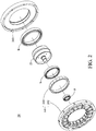
- FIG. 2 shows the exploded drawing of the electromagnetic spring of the embodiment;
- FIG. 3 shows the exploded drawing of the gear set of the embodiment.
- the electromagnetic spring 24 may include a spring main body SB, a gear set 23, a rear cover 243 and a plurality of bearings B; the spring main body SB may include a rotor 241, a gear set 242; the spring main body SB and the gear set 23 may be mounted on the rear cover 243; the gear set 23 may include a first input shaft, a second input shaft and an output shaft.
- the stator may be hollow, and may include a stator lamination 2421 and a stator coil 2422.
- the rotor may be hollow, and may include a back iron and a magnet set; the rotor 241 may be disposed in the accommodating space inside the stator 242, and the gear set 23 may be disposed in the accommodating space inside the rotor 241.
- the slot number of the stator 242 may be the integral multiple of the pole number of the rotor 241, so the electromagnetic spring 24 may have higher elasticity coefficient; in the embodiment, the slot number of the stator 242 may be 18, and the pole number of the rotor 241 may be also 18.
- the gear set 23 may be a planetary gear set, which may include a sun gear 231, a ring gear 232, a planet carrier 233 and a plurality of planet gears 234.
- the ring gear 232 may be the first input shaft, and the sun gear 231 may be the second input shaft.
- the sun gear 231, the ring gear 232, the planet carrier 233 and the planet gears 234 may be coupled with one another.
- the planet carrier 233 may include a planet carrier front cover 2331 and a planet carrier rear cover 2332; the planet carrier front cover 2331 may include a cup-shaped planet carrier extension part, which may serve as the output shaft of the electromagnetic spring 24.
- the gear set 23 may be disposed in the accommodating space inside the rotor 241, and the ring gear 232 of the gear set 23 may connect to rotor 241; the power generated by the rotor 241 and the power inputted from the sun gear 231 may be coupled and then outputted from the planet carrier 233.
- the stator 242 and the rotor 241 of the electromagnetic spring 24 may be hollow, so the rotor 241 may be disposed in the accommodating space inside the stator 242, and the gear set 23 may be disposed in the accommodating space of the rotor 241.
- the gear set 23 may be directly integrated with the spring main body SB of the electromagnetic spring 24.
- the above special structure design can significantly decrease the size of the electromagnetic spring 24.
- the elasticity coefficient of the electromagnetic spring 24 can be directly adjusted by controlling the current in order to change its output stiffness; thus, the electromagnetic spring 24 can have high operation response.
- FIG. 4 is a fourth schematic view of a first embodiment of an electromagnetic spring in accordance with the present disclosure.
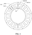
- FIG. 4 illustrates a preferred structure of the stator of the electromagnetic spring of the embodiment.
- the stator 242 may be hollow, and may include the stator lamination 2421 and the stator coil 2422.
- the stator coil 2422 may be the single phase serial winding.
- the stator lamination 2421 may include a plurality of first stator teeth 24211A, and the stator coil 2422 may be wound on the first stator teeth 24211A.
- the stator lamination 2421 may further include a pair of second stator teeth 24211B, and the second stator tooth 24211B may be slightly shorter than the first stator tooth 24211A; therefore, a space may be formed between the tooth shoe of each of the second stator teeth 24211B and the rotor 241, and the tooth shoe of each of the second stator teeth 24211B may mount a magnet ES.
- the special magnet auxiliary structure composed of the second stator teeth 24211B and the magnets ES can effectively increase the electromagnetic field generated by the stator coil 2422, so the electromagnetic spring 24 can still provide the spring effect without power supply. In this way, the electromagnetic spring 24 can have better performance.
- FIG. 5 and FIG. 6 is a fifth schematic view and a sixth schematic view of a first embodiment of an electromagnetic spring in accordance with the present disclosure.
- FIG. 5 and FIG. 6 illustrate several preferred structures of the stator of the electromagnetic spring of the embodiment.
- the magnet auxiliary structure of the electromagnetic spring 24 of the embodiment may be modified according to the requirements; as shown in FIG. 5 , the stator lamination 2421 may include a plurality of first stator teeth 24221A and 3 pairs of the second stator teeth 24211B.
- the stator coil 2422 may be wound on the first stator teeth 24211A.
- the second stator tooth 24211B may be slightly shorter than the first stator tooth 24211A; therefore, a space may be formed between the tooth shoe of each of the second stator teeth 24211B and the rotor 241, and the tooth shoe of each of the second stator teeth 24211B may mount a magnet ES.
- the above magnet auxiliary structure can further increase the electromagnetic field generated by the stator coil 2422, so the electromagnetic spring 24 can still provide the spring effect without power supply. In this way, the electromagnetic spring 24 can have better performance.
- the electromagnetic spring 24 may have no the aforementioned magnet auxiliary structure; in other words, the stator lamination 2421 may only include a plurality of first stator teeth 24211A, but have no the second stator tooth 24211B.
- FIG. 7 , FIG. 8 and FIG. 9 are a first schematic view, a second schematic view and a third schematic view of a first embodiment of an elastic actuator in accordance with the present disclosure.
- FIG. 7 shows the assembly drawing of the elastic actuator of the embodiment;
- FIG. 8 shows the exploded drawing of the elastic actuator of the embodiment;
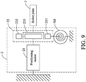
- FIG. 9 shows the assembly drawing of the elastic actuator and a robot joint.
- the elastic actuator of the embodiment can use the electromagnetic spring to adjust its output stiffness.
- the elastic actuator 2 may include a positioning motor 21 and an electromagnetic spring 24; the positioning motor 21 may include a motor output shaft 211; in a preferred embodiment, the positioning motor 21 may be a servo motor.
- the electromagnetic spring may include a spring main body SB, a gear set 23, a rear cover 243 and a plurality of bearings; the spring main body SB may include a rotor 241 and a stator 242; the spring main body SB and the gear set 23 may be mounted on the rear cover 243; the gear set 23 may include a first input shaft, a second input shaft and an output shaft.
- the gear set 23 may be a planetary gear set, which may include a sun gear, a ring gear, a planet carrier and a plurality of planet gears.
- the ring gear may be the first input shaft
- the sun gear 231 may be the second input shaft and the planet carrier may be the output shaft.
- the sun gear, the ring gear, the planet carrier and the planet gears may be coupled with one another; the detailed structure of the gear set 23 is the same with previous embodiment, so will not be described therein again.
- FIG. 9 illustrates a preferred connection structure of the elastic actuator 2 of the embodiment and a robot joint J, which is a parallel connection structure.
- the spring main body SB may connect to the ring gear 232
- the positioning motor 21 may connect to the sun gear 231
- the planet carrier 233 may connect to the robot joint J; therefore, the power generated by the spring main body SB and the power generated by the positioning motor 21 may be coupled and then outputted to the robot joint J via the planet carrier 233.
- the elastic actuator 2 can directly use the electromagnetic spring 24 to adjust its output stiffness, the overall structure of the elastic actuator 2 can be simplified; therefore, the size, weight and cost of the elastic actuator 2 can be significantly reduced.
- the elastic actuator may include an electromagnetic spring, so the output stiffness of the elastic actuator can be freely adjusted according to the requirements, which is more flexible in use.
- the elastic actuator may adopt the electromagnetic spring, so the size and the weight of the elastic actuator can be significantly reduced.
- the elastic actuator may adopt the electromagnetic spring, so the overall structure of the elastic actuator can be simplified; thus, the cost of the electromagnetic spring can be reduced.
- the electromagnetic spring can be controlled by adjusting current, so the operation response of the electromagnetic spring can be very high.
- the slot number of the electromagnetic spring is the integral multiple of its pole number, so the elasticity coefficient of the electromagnetic spring can dramatically increase.
- the stator coil of the electromagnetic spring may adopt single phase serial winding, which further simplifies the structure of the electromagnetic spring; thus, the cost of the electromagnetic spring can be further reduced.
- the stator of the electromagnetic spring may include a magnet auxiliary structure, which may increase the electromagnetic field generated by the stator coil, so the electromagnetic spring can still provide the spring effect without power supply; therefore, the electromagnetic spring can have better performance.
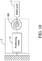
- FIG. 10 is a schematic view of a second embodiment of an elastic actuator in accordance with the present disclosure
- FIG. 10 illustrates another preferred connection structure of the elastic actuator 2 of the embodiment and a robot joint J; the difference between the embodiment and the previous embodiment is that the embodiment adopts serial connection structure.
- the elastic actuator may include an electromagnetic spring, so the output stiffness of the elastic actuator can be freely adjusted according to the requirements.
- the elastic actuator may adopt the electromagnetic spring, so the size and the weight of the elastic actuator can be significantly reduced.
- the elastic actuator may adopt the electromagnetic spring, so the overall structure of the elastic actuator can be simplified; thus, the cost of the electromagnetic spring can be reduced.
- the electromagnetic spring can be controlled by adjusting current, so the operation response of the electromagnetic spring can be very high.
- the slot number of the electromagnetic spring is the integral multiple of its pole number, so the elasticity coefficient of the electromagnetic spring can dramatically increase.
- the stator coil of the electromagnetic spring may adopt single phase serial winding, which further simplifies the structure of the electromagnetic spring; thus, the cost of the electromagnetic spring can be further reduced.
- the stator of the electromagnetic spring may include a magnet auxiliary structure, which may increase the electromagnetic field generated by the stator coil, so the electromagnetic spring can still provide the spring effect without power supply; therefore, the electromagnetic spring can have better performance.
Landscapes
- Engineering & Computer Science (AREA)
- General Engineering & Computer Science (AREA)
- Mechanical Engineering (AREA)
- Physics & Mathematics (AREA)
- Robotics (AREA)
- Electromagnetism (AREA)
- Acoustics & Sound (AREA)
- Aviation & Aerospace Engineering (AREA)
- Power Engineering (AREA)
- Connection Of Motors, Electrical Generators, Mechanical Devices, And The Like (AREA)
- Reciprocating, Oscillating Or Vibrating Motors (AREA)
Claims (21)
- Elektromagnetische Feder (24), dadurch gekennzeichnet, dass die elektromagnetische Feder (24) umfasst:einen Rotor (241);einen Stator (242), der betreibbar ist, um eine Drehung des Rotors (241) zu bremsen;einen Getriebesatz (23), der eine erste Eingangswelle (232), eine zweite Eingangswelle (231) und eine Ausgangswelle umfasst, wobei die zweite Eingangswelle (231) mit dem Rotor (241) verbunden ist, und eine von dem Rotor (241) erzeugte Leistung und eine von der ersten Eingangswelle (232) eingegebene externe Leistung über den Getriebesatz (23) gekoppelt und dann von der Ausgangswelle ausgegeben werden.
- Elektromagnetische Feder (24) nach Anspruch 1, dadurch gekennzeichnet, dass der Stator (242) hohl ist, und der Rotor (241) in einem Aufnahmeraum innerhalb des Stators (242) angeordnet ist.
- Elektromagnetische Feder (24) nach Anspruch 1, dadurch gekennzeichnet, dass der Getriebesatz (23) ein Planetengetriebesatz ist, und ein Hohlrad (232) des Planetengetriebesatzes mit dem Rotor (241) verbunden ist, und die vom Rotor (241) erzeugte Leistung und eine von einem Sonnenrad (231) des Planetengetriebesatzes aufgenommene Leistung gekoppelt und dann von einem Planetenträger (233) des Planetengetriebesatzes ausgegeben wird.
- Elektromagnetische Feder (24) nach Anspruch 1, dadurch gekennzeichnet, dass eine Zahl von Aussparungen der elektromagnetischen Feder (24) ein ganzzahliges Vielfaches einer Polzahl der elektromagnetischen Feder (24) ist.
- Elektromagnetische Feder (24) nach Anspruch 1, dadurch gekennzeichnet, dass eine Zahl der Aussparungen der elektromagnetischen Feder (24) 18 ist und eine Polzahl der elektromagnetischen Feder (24) 18 ist.
- Elektromagnetische Feder (24) nach Anspruch 1, dadurch gekennzeichnet, dass der Stator (242) eine Statorspule (2422) und eine Statorlamellierung (2421) umfasst; wobei die Statorlamellierung (2421) eine Mehrzahl von ersten Statorzähnen (24211A) umfasst und die Statorspule (2422) auf die ersten Statorzähne (24211A) gewickelt ist.
- Elektromagnetische Feder (24) nach Anspruch 2, dadurch gekennzeichnet, dass der Rotor (241) hohl ist, und der Getriebesatz (23) in einem Aufnahmeraum innerhalb des Rotors (241) angeordnet ist.
- Elektromagnetische Feder (24) nach Anspruch 6, dadurch gekennzeichnet, dass die Statorspule (2422) eine einphasige Serienwicklung ist.
- Elektromagnetische Feder (24) nach Anspruch 6, dadurch gekennzeichnet, dass die Statorlamellierung (2421) ferner eine Vielzahl von zweiten Statorzähnen (24211B) umfasst, und an einem Zahnschuh jedes der zweiten Zähne ein Magneten (ES) angebracht ist.
- Elektromagnetische Feder (24) nach Anspruch 7, dadurch gekennzeichnet, dass die elektromagnetische Feder (24) weiterhin eine hintere Abdeckung (243) umfasst, wobei die hintere Abdeckung (243) hohl ist und der Rotor (241), der Stator (242) und der Getriebesatz (23) auf der hinteren Abdeckung (243) angeordnet sind.
- Elastischer Aktuator (2), dadurch gekennzeichnet, dass der elastische Aktuator (2) umfasst:einen Positionsmotor (21), der eine Motorausgangswelle aufweist; undeine elektromagnetische Feder (24) nach Anspruch 1,wobei die erste Eingangswelle (232) mit der Motorausgangswelle verbunden ist, und die Kraft durch den Positionsmotor (21) erzeugt wird.
- Elastischer Aktuator (2) nach Anspruch 11, dadurch gekennzeichnet, dass der Stator (242) hohl ist, und der Rotor (241) in einem Aufnahmeraum innerhalb des Stators (242) angeordnet ist.
- Elastischer Aktuator (2) nach Anspruch 11, dadurch gekennzeichnet, dass der Getriebesatz (23) ein Planetengetriebesatz ist und ein Hohlrad (23) des Planetengetriebesatzes mit dem Rotor (241) verbunden ist, und die vom Rotor (241) erzeugte Leistung und eine von einem Sonnenrad (231) des Planetengetriebesatzes aufgenommene Leistung gekoppelt und dann von einem Planetenträger (233) des Planetengetriebesatzes ausgegeben wird.
- Elastischer Aktor (2) nach Anspruch 11, dadurch gekennzeichnet, dass eine Zahl von Aussparungen der elektromagnetischen Feder (24) ein ganzzahliges Vielfaches einer Polzahl der elektromagnetischen Feder (24) ist.
- Elastischer Aktuator (2) nach Anspruch 11, dadurch gekennzeichnet, dass eine Zahl von Aussparungen der elektromagnetischen Feder (24) 18 ist und eine Polzahl der elektromagnetischen Feder (24) 18 ist.
- Elastischer Aktuator (2) nach Anspruch 11, dadurch gekennzeichnet, dass der Stator (242) eine Statorspule (2422) und eine Statorlamellierung (2421) umfasst; wobei die Statorlamellierung (2421) eine Mehrzahl von ersten Statorzähnen (24211A) umfasst und die Statorspule (2422) auf die ersten Statorzähne (24211A) gewickelt ist.
- Elastischer Aktuator (2) nach Anspruch 11, dadurch gekennzeichnet, dass der Positionsmotor ein Servomotor ist.
- Elastischer Stellantrieb (2) nach Anspruch 12, dadurch gekennzeichnet, dass der Rotor (241) hohl ist und der Getriebesatz (23) in einem Aufnahmeraum innerhalb des Rotors (241) angeordnet ist.
- Elastischer Aktuator (2) nach Anspruch 16, dadurch gekennzeichnet, dass die Statorspule (2422) eine einphasige Serienwicklung ist.
- Elastischer Aktuator (2) nach Anspruch 16, dadurch gekennzeichnet, dass die Statorlamellierung (2421) ferner eine Vielzahl von zweiten Statorzähnen (24211B) umfasst, und ein Zahnschuh jedes der zweiten Zähne (24211B) einen Magneten (ES) trägt.
- Elastischer Aktuator (2) nach Anspruch 18, dadurch gekennzeichnet, dass die elektromagnetische Feder (24) weiterhin eine hintere Abdeckung (243) umfasst und die hintere Abdeckung (243) hohl ist; der Rotor (241), der Stator (242) und der Getriebesatz (23) auf der hinteren Abdeckung (243) angeordnet sind.
Applications Claiming Priority (1)
| Application Number | Priority Date | Filing Date | Title |
|---|---|---|---|
| TW105121954A TWI592588B (zh) | 2016-07-12 | 2016-07-12 | 電磁彈簧及包含此電磁彈簧的彈性致動器 |
Publications (2)
| Publication Number | Publication Date |
|---|---|
| EP3269999A1 EP3269999A1 (de) | 2018-01-17 |
| EP3269999B1 true EP3269999B1 (de) | 2021-06-23 |
Family
ID=57281078
Family Applications (1)
| Application Number | Title | Priority Date | Filing Date |
|---|---|---|---|
| EP16197879.6A Active EP3269999B1 (de) | 2016-07-12 | 2016-11-09 | Elektromagnetische feder und elastischer aktuator damit |
Country Status (3)
| Country | Link |
|---|---|
| US (1) | US10367394B2 (de) |
| EP (1) | EP3269999B1 (de) |
| TW (1) | TWI592588B (de) |
Families Citing this family (3)
| Publication number | Priority date | Publication date | Assignee | Title |
|---|---|---|---|---|
| JP6758211B2 (ja) * | 2017-02-03 | 2020-09-23 | アズビル株式会社 | 操作器 |
| TWI763544B (zh) | 2021-06-18 | 2022-05-01 | 財團法人工業技術研究院 | 致動器 |
| US11994390B2 (en) * | 2022-02-09 | 2024-05-28 | Honeywell International Inc. | Vibratory sensor with electronic balancing |
Family Cites Families (33)
| Publication number | Priority date | Publication date | Assignee | Title |
|---|---|---|---|---|
| US5502363A (en) | 1994-01-04 | 1996-03-26 | University Of Maryland-Baltimore County | Apparatus for controlling angular positioning and stiffness modulations of joint of robotic manipulator |
| JP3209409B2 (ja) | 1997-07-31 | 2001-09-17 | 小倉クラッチ株式会社 | 電磁スプリングクラッチ |
| JP2002021876A (ja) * | 2000-07-10 | 2002-01-23 | Toyota Industries Corp | 電磁スプリングクラッチ |
| EP1803168A4 (de) | 2004-10-21 | 2009-05-20 | Michelin Soc Tech | Miniaturisierte, auf piezoelektrik basierende vibrationsenergie-sammelvorrichtung |
| US8933607B1 (en) * | 2005-01-18 | 2015-01-13 | Revolution Electric Motor Company, Inc. | High efficiency air core motor-generator |
| US8500823B2 (en) | 2005-03-31 | 2013-08-06 | Massachusetts Institute Of Technology | Powered artificial knee with agonist-antagonist actuation |
| WO2007067704A2 (en) | 2005-12-07 | 2007-06-14 | Bei Sensors And Systems Company, Inc. | Linear voice coil actuator as a bi-directional electromagnetic spring |
| TWM293393U (en) | 2006-01-16 | 2006-07-01 | Chuen-Chang Li | Improved xenon lamp base |
| DE102006022491A1 (de) | 2006-05-13 | 2008-01-17 | Chr. Mayr Gmbh & Co. Kg | Geräuschdämpfung Bremse |
| DE202007014518U1 (de) | 2007-10-17 | 2007-12-20 | Chr. Mayr Gmbh + Co. Kg | Vier-Segment-Bremse |
| DE102008043144B4 (de) | 2008-10-24 | 2017-08-17 | Robert Bosch Gmbh | Vorrichtung zur Fixierung von Magneten |
| TWI357471B (en) | 2008-11-19 | 2012-02-01 | Jiun Yih Kuan | Force-controllable adaptive coupled elastic actuat |
| TW201105467A (en) | 2009-08-04 | 2011-02-16 | Mirle Automation Corp | Robotic fashion model |
| KR101706094B1 (ko) | 2010-01-14 | 2017-02-14 | 삼성전자주식회사 | 로봇용 관절 구동장치 및 이를 포함하는 로봇, 로봇용 관절 구동장치의 케이블 연결방법 |
| US8525460B2 (en) | 2010-02-02 | 2013-09-03 | GM Global Technology Operations LLC | Architecture for robust force and impedance control of series elastic actuators |
| DE102010003431B4 (de) | 2010-03-30 | 2019-05-16 | Seg Automotive Germany Gmbh | Startvorrichtung mit Hohlrad- und Zwischenlagerdämpfung |
| WO2011126985A2 (en) | 2010-04-05 | 2011-10-13 | Iwalk, Inc. | Controlling torque in a prosthesis or orthosis |
| ITTO20100360A1 (it) | 2010-04-28 | 2011-10-29 | Fond Istituto Italiano Di Tecnologia | Attuatore rotante elastico, particolarmente per applicazioni robotiche, con dispositivo di smorzamento semiattivo |
| TWI374800B (en) | 2010-06-24 | 2012-10-21 | Univ Nat Taiwan | Compliant torque output device |
| CN101934525B (zh) | 2010-09-15 | 2012-07-25 | 北京航空航天大学 | 仿人机器人可变刚度柔性关节设计 |
| TR201807071T4 (tr) | 2011-06-21 | 2018-06-21 | Univ Sabanci | Diş i̇skelet. |
| WO2013003241A2 (en) * | 2011-06-30 | 2013-01-03 | Mcintosh Devon R | Low-cost low-cog pm machine |
| US9564779B2 (en) * | 2011-10-14 | 2017-02-07 | Mitsubishi Electric Corporation | Permanent magnet motor |
| CN102632508B (zh) | 2012-04-17 | 2015-04-29 | 浙江大学 | 一种适用于机器人关节的平面扭簧 |
| US9079305B2 (en) | 2012-08-28 | 2015-07-14 | Rethink Robotics, Inc. | Monitoring robot sensor consistency |
| US20140100491A1 (en) | 2012-10-05 | 2014-04-10 | Jianjuen Hu | Lower Extremity Robotic Rehabilitation System |
| JP5997581B2 (ja) * | 2012-10-24 | 2016-09-28 | セイコーエプソン株式会社 | 電気機械装置、並びに、これを備える移動体およびロボット |
| US8900087B2 (en) * | 2013-03-15 | 2014-12-02 | Francis Daly Ward | Multi-speed inline automatic bicycle transmission |
| EP2989345B1 (de) | 2013-04-24 | 2019-04-10 | Marquette University | Aktuator mit variabler steifigkeit und grossem steifheitsbereich |
| US9239100B1 (en) | 2013-06-24 | 2016-01-19 | Meka Robotics, LLC | Rotary series elastic actuator |
| TWI538363B (zh) | 2014-12-02 | 2016-06-11 | 財團法人工業技術研究院 | 順應性馬達結構及其製造方法 |
| TWM519487U (zh) | 2015-09-04 | 2016-04-01 | Lee Ai Ju | 醫學檢驗用的偵檢設備 |
| CN105587812B (zh) | 2016-03-15 | 2018-05-18 | 哈尔滨工程大学 | 一种具有线性负刚度特性的电磁弹簧 |
-
2016
- 2016-07-12 TW TW105121954A patent/TWI592588B/zh active
- 2016-11-04 US US15/343,758 patent/US10367394B2/en active Active
- 2016-11-09 EP EP16197879.6A patent/EP3269999B1/de active Active
Non-Patent Citations (1)
| Title |
|---|
| None * |
Also Published As
| Publication number | Publication date |
|---|---|
| US20180019639A1 (en) | 2018-01-18 |
| TW201809497A (zh) | 2018-03-16 |
| TWI592588B (zh) | 2017-07-21 |
| EP3269999A1 (de) | 2018-01-17 |
| US10367394B2 (en) | 2019-07-30 |
Similar Documents
| Publication | Publication Date | Title |
|---|---|---|
| US9752665B2 (en) | Compliance motor structure and manufacturing method thereof | |
| US10367394B2 (en) | Electromagnetic spring and elastic actuator having the same | |
| US7777385B2 (en) | Compact, electromagnetically braked actuator assembly | |
| CN107378915A (zh) | 一种基于能量回馈的下肢助力装置 | |
| CN102377306B (zh) | 旋转电机、风力发电系统和旋转电机的制造方法 | |
| TW201808718A (zh) | 輪轂式馬達減速機 | |
| JP3186812U (ja) | 変速伝動ベアリング | |
| CN111466070B (zh) | 执行器 | |
| JP2019041567A (ja) | 反転ハーモニックギヤアクチュエータ及び反転ハーモニックギヤアクチュエータの組立方法 | |
| CN105048714B (zh) | 一种一体化的丝杠机电惯容器 | |
| JP7050534B2 (ja) | ポンプ装置 | |
| CN103490555B (zh) | 一种单偏心轴式啮合电动机 | |
| CN110714997B (zh) | 一种集成磁流体刹车的轮电机驱动器 | |
| US11689087B2 (en) | Permanent magnet motor with field weakening arrangement | |
| JP5914102B2 (ja) | 磁気機能装置 | |
| TWI793273B (zh) | 具有閉合迴路滑動帶之改良式體操機 | |
| NL2021361B1 (en) | Electric low-power supply system for devices and device comprising such a low-power supply system | |
| KR20110012177A (ko) | 가속기를 갖는 회전자 및 그를 포함하는 bldc 모터 | |
| CN206647504U (zh) | 行星齿轮脚踝用双自由度舵机及机器人 | |
| KR20190018401A (ko) | 다중의 회전자 및 고정자로 구성되는 발전기 | |
| CN104953786A (zh) | 基于铰链四杆机构的超磁致伸缩步进电机 | |
| CN104048017A (zh) | 一种齿轮动态消隙装置 | |
| Chang et al. | A new compliant actuation: Electromagnetic spring uses in parallel elastic actuator | |
| CN105379071B (zh) | 具有低短路转矩的电动电机、具有多个电机的驱动装置、和制造这种电机的方法 | |
| CN203570873U (zh) | 一种三速电磁离合器总成 |
Legal Events
| Date | Code | Title | Description |
|---|---|---|---|
| PUAI | Public reference made under article 153(3) epc to a published international application that has entered the european phase |
Free format text: ORIGINAL CODE: 0009012 |
|
| STAA | Information on the status of an ep patent application or granted ep patent |
Free format text: STATUS: REQUEST FOR EXAMINATION WAS MADE |
|
| 17P | Request for examination filed |
Effective date: 20161208 |
|
| AK | Designated contracting states |
Kind code of ref document: A1 Designated state(s): AL AT BE BG CH CY CZ DE DK EE ES FI FR GB GR HR HU IE IS IT LI LT LU LV MC MK MT NL NO PL PT RO RS SE SI SK SM TR |
|
| AX | Request for extension of the european patent |
Extension state: BA ME |
|
| STAA | Information on the status of an ep patent application or granted ep patent |
Free format text: STATUS: EXAMINATION IS IN PROGRESS |
|
| 17Q | First examination report despatched |
Effective date: 20191108 |
|
| GRAP | Despatch of communication of intention to grant a patent |
Free format text: ORIGINAL CODE: EPIDOSNIGR1 |
|
| STAA | Information on the status of an ep patent application or granted ep patent |
Free format text: STATUS: GRANT OF PATENT IS INTENDED |
|
| INTG | Intention to grant announced |
Effective date: 20210120 |
|
| GRAS | Grant fee paid |
Free format text: ORIGINAL CODE: EPIDOSNIGR3 |
|
| GRAA | (expected) grant |
Free format text: ORIGINAL CODE: 0009210 |
|
| STAA | Information on the status of an ep patent application or granted ep patent |
Free format text: STATUS: THE PATENT HAS BEEN GRANTED |
|
| AK | Designated contracting states |
Kind code of ref document: B1 Designated state(s): AL AT BE BG CH CY CZ DE DK EE ES FI FR GB GR HR HU IE IS IT LI LT LU LV MC MK MT NL NO PL PT RO RS SE SI SK SM TR |
|
| REG | Reference to a national code |
Ref country code: GB Ref legal event code: FG4D |
|
| REG | Reference to a national code |
Ref country code: CH Ref legal event code: EP |
|
| REG | Reference to a national code |
Ref country code: DE Ref legal event code: R096 Ref document number: 602016059602 Country of ref document: DE Ref country code: AT Ref legal event code: REF Ref document number: 1404569 Country of ref document: AT Kind code of ref document: T Effective date: 20210715 |
|
| REG | Reference to a national code |
Ref country code: IE Ref legal event code: FG4D |
|
| REG | Reference to a national code |
Ref country code: LT Ref legal event code: MG9D |
|
| PG25 | Lapsed in a contracting state [announced via postgrant information from national office to epo] |
Ref country code: LT Free format text: LAPSE BECAUSE OF FAILURE TO SUBMIT A TRANSLATION OF THE DESCRIPTION OR TO PAY THE FEE WITHIN THE PRESCRIBED TIME-LIMIT Effective date: 20210623 Ref country code: FI Free format text: LAPSE BECAUSE OF FAILURE TO SUBMIT A TRANSLATION OF THE DESCRIPTION OR TO PAY THE FEE WITHIN THE PRESCRIBED TIME-LIMIT Effective date: 20210623 Ref country code: BG Free format text: LAPSE BECAUSE OF FAILURE TO SUBMIT A TRANSLATION OF THE DESCRIPTION OR TO PAY THE FEE WITHIN THE PRESCRIBED TIME-LIMIT Effective date: 20210923 Ref country code: HR Free format text: LAPSE BECAUSE OF FAILURE TO SUBMIT A TRANSLATION OF THE DESCRIPTION OR TO PAY THE FEE WITHIN THE PRESCRIBED TIME-LIMIT Effective date: 20210623 |
|
| REG | Reference to a national code |
Ref country code: AT Ref legal event code: MK05 Ref document number: 1404569 Country of ref document: AT Kind code of ref document: T Effective date: 20210623 |
|
| PG25 | Lapsed in a contracting state [announced via postgrant information from national office to epo] |
Ref country code: LV Free format text: LAPSE BECAUSE OF FAILURE TO SUBMIT A TRANSLATION OF THE DESCRIPTION OR TO PAY THE FEE WITHIN THE PRESCRIBED TIME-LIMIT Effective date: 20210623 Ref country code: GR Free format text: LAPSE BECAUSE OF FAILURE TO SUBMIT A TRANSLATION OF THE DESCRIPTION OR TO PAY THE FEE WITHIN THE PRESCRIBED TIME-LIMIT Effective date: 20210924 Ref country code: NO Free format text: LAPSE BECAUSE OF FAILURE TO SUBMIT A TRANSLATION OF THE DESCRIPTION OR TO PAY THE FEE WITHIN THE PRESCRIBED TIME-LIMIT Effective date: 20210923 Ref country code: RS Free format text: LAPSE BECAUSE OF FAILURE TO SUBMIT A TRANSLATION OF THE DESCRIPTION OR TO PAY THE FEE WITHIN THE PRESCRIBED TIME-LIMIT Effective date: 20210623 Ref country code: SE Free format text: LAPSE BECAUSE OF FAILURE TO SUBMIT A TRANSLATION OF THE DESCRIPTION OR TO PAY THE FEE WITHIN THE PRESCRIBED TIME-LIMIT Effective date: 20210623 |
|
| REG | Reference to a national code |
Ref country code: NL Ref legal event code: MP Effective date: 20210623 |
|
| PG25 | Lapsed in a contracting state [announced via postgrant information from national office to epo] |
Ref country code: SK Free format text: LAPSE BECAUSE OF FAILURE TO SUBMIT A TRANSLATION OF THE DESCRIPTION OR TO PAY THE FEE WITHIN THE PRESCRIBED TIME-LIMIT Effective date: 20210623 Ref country code: SM Free format text: LAPSE BECAUSE OF FAILURE TO SUBMIT A TRANSLATION OF THE DESCRIPTION OR TO PAY THE FEE WITHIN THE PRESCRIBED TIME-LIMIT Effective date: 20210623 Ref country code: EE Free format text: LAPSE BECAUSE OF FAILURE TO SUBMIT A TRANSLATION OF THE DESCRIPTION OR TO PAY THE FEE WITHIN THE PRESCRIBED TIME-LIMIT Effective date: 20210623 Ref country code: CZ Free format text: LAPSE BECAUSE OF FAILURE TO SUBMIT A TRANSLATION OF THE DESCRIPTION OR TO PAY THE FEE WITHIN THE PRESCRIBED TIME-LIMIT Effective date: 20210623 Ref country code: AT Free format text: LAPSE BECAUSE OF FAILURE TO SUBMIT A TRANSLATION OF THE DESCRIPTION OR TO PAY THE FEE WITHIN THE PRESCRIBED TIME-LIMIT Effective date: 20210623 Ref country code: PT Free format text: LAPSE BECAUSE OF FAILURE TO SUBMIT A TRANSLATION OF THE DESCRIPTION OR TO PAY THE FEE WITHIN THE PRESCRIBED TIME-LIMIT Effective date: 20211025 Ref country code: NL Free format text: LAPSE BECAUSE OF FAILURE TO SUBMIT A TRANSLATION OF THE DESCRIPTION OR TO PAY THE FEE WITHIN THE PRESCRIBED TIME-LIMIT Effective date: 20210623 Ref country code: RO Free format text: LAPSE BECAUSE OF FAILURE TO SUBMIT A TRANSLATION OF THE DESCRIPTION OR TO PAY THE FEE WITHIN THE PRESCRIBED TIME-LIMIT Effective date: 20210623 Ref country code: ES Free format text: LAPSE BECAUSE OF FAILURE TO SUBMIT A TRANSLATION OF THE DESCRIPTION OR TO PAY THE FEE WITHIN THE PRESCRIBED TIME-LIMIT Effective date: 20210623 |
|
| PG25 | Lapsed in a contracting state [announced via postgrant information from national office to epo] |
Ref country code: PL Free format text: LAPSE BECAUSE OF FAILURE TO SUBMIT A TRANSLATION OF THE DESCRIPTION OR TO PAY THE FEE WITHIN THE PRESCRIBED TIME-LIMIT Effective date: 20210623 |
|
| REG | Reference to a national code |
Ref country code: DE Ref legal event code: R097 Ref document number: 602016059602 Country of ref document: DE |
|
| PG25 | Lapsed in a contracting state [announced via postgrant information from national office to epo] |
Ref country code: DK Free format text: LAPSE BECAUSE OF FAILURE TO SUBMIT A TRANSLATION OF THE DESCRIPTION OR TO PAY THE FEE WITHIN THE PRESCRIBED TIME-LIMIT Effective date: 20210623 |
|
| PLBE | No opposition filed within time limit |
Free format text: ORIGINAL CODE: 0009261 |
|
| STAA | Information on the status of an ep patent application or granted ep patent |
Free format text: STATUS: NO OPPOSITION FILED WITHIN TIME LIMIT |
|
| 26N | No opposition filed |
Effective date: 20220324 |
|
| PG25 | Lapsed in a contracting state [announced via postgrant information from national office to epo] |
Ref country code: AL Free format text: LAPSE BECAUSE OF FAILURE TO SUBMIT A TRANSLATION OF THE DESCRIPTION OR TO PAY THE FEE WITHIN THE PRESCRIBED TIME-LIMIT Effective date: 20210623 |
|
| PG25 | Lapsed in a contracting state [announced via postgrant information from national office to epo] |
Ref country code: MC Free format text: LAPSE BECAUSE OF FAILURE TO SUBMIT A TRANSLATION OF THE DESCRIPTION OR TO PAY THE FEE WITHIN THE PRESCRIBED TIME-LIMIT Effective date: 20210623 |
|
| REG | Reference to a national code |
Ref country code: CH Ref legal event code: PL |
|
| GBPC | Gb: european patent ceased through non-payment of renewal fee |
Effective date: 20211109 |
|
| PG25 | Lapsed in a contracting state [announced via postgrant information from national office to epo] |
Ref country code: LU Free format text: LAPSE BECAUSE OF NON-PAYMENT OF DUE FEES Effective date: 20211109 Ref country code: IT Free format text: LAPSE BECAUSE OF FAILURE TO SUBMIT A TRANSLATION OF THE DESCRIPTION OR TO PAY THE FEE WITHIN THE PRESCRIBED TIME-LIMIT Effective date: 20210623 Ref country code: BE Free format text: LAPSE BECAUSE OF NON-PAYMENT OF DUE FEES Effective date: 20211130 |
|
| REG | Reference to a national code |
Ref country code: BE Ref legal event code: MM Effective date: 20211130 |
|
| PG25 | Lapsed in a contracting state [announced via postgrant information from national office to epo] |
Ref country code: LI Free format text: LAPSE BECAUSE OF NON-PAYMENT OF DUE FEES Effective date: 20211130 Ref country code: CH Free format text: LAPSE BECAUSE OF NON-PAYMENT OF DUE FEES Effective date: 20211130 |
|
| PG25 | Lapsed in a contracting state [announced via postgrant information from national office to epo] |
Ref country code: IE Free format text: LAPSE BECAUSE OF NON-PAYMENT OF DUE FEES Effective date: 20211109 Ref country code: GB Free format text: LAPSE BECAUSE OF NON-PAYMENT OF DUE FEES Effective date: 20211109 |
|
| PG25 | Lapsed in a contracting state [announced via postgrant information from national office to epo] |
Ref country code: FR Free format text: LAPSE BECAUSE OF NON-PAYMENT OF DUE FEES Effective date: 20211130 |
|
| PG25 | Lapsed in a contracting state [announced via postgrant information from national office to epo] |
Ref country code: HU Free format text: LAPSE BECAUSE OF FAILURE TO SUBMIT A TRANSLATION OF THE DESCRIPTION OR TO PAY THE FEE WITHIN THE PRESCRIBED TIME-LIMIT; INVALID AB INITIO Effective date: 20161109 |
|
| PG25 | Lapsed in a contracting state [announced via postgrant information from national office to epo] |
Ref country code: CY Free format text: LAPSE BECAUSE OF FAILURE TO SUBMIT A TRANSLATION OF THE DESCRIPTION OR TO PAY THE FEE WITHIN THE PRESCRIBED TIME-LIMIT Effective date: 20210623 |
|
| PG25 | Lapsed in a contracting state [announced via postgrant information from national office to epo] |
Ref country code: MK Free format text: LAPSE BECAUSE OF FAILURE TO SUBMIT A TRANSLATION OF THE DESCRIPTION OR TO PAY THE FEE WITHIN THE PRESCRIBED TIME-LIMIT Effective date: 20210623 |
|
| PG25 | Lapsed in a contracting state [announced via postgrant information from national office to epo] |
Ref country code: MT Free format text: LAPSE BECAUSE OF FAILURE TO SUBMIT A TRANSLATION OF THE DESCRIPTION OR TO PAY THE FEE WITHIN THE PRESCRIBED TIME-LIMIT Effective date: 20210623 |
|
| PG25 | Lapsed in a contracting state [announced via postgrant information from national office to epo] |
Ref country code: TR Free format text: LAPSE BECAUSE OF FAILURE TO SUBMIT A TRANSLATION OF THE DESCRIPTION OR TO PAY THE FEE WITHIN THE PRESCRIBED TIME-LIMIT Effective date: 20210623 |
|
| PGFP | Annual fee paid to national office [announced via postgrant information from national office to epo] |
Ref country code: DE Payment date: 20251128 Year of fee payment: 10 |