EP3269307B1 - Röntgenaufnahmevorrichtung und röntgenaufnahmeerzeugungsverfahren - Google Patents
Röntgenaufnahmevorrichtung und röntgenaufnahmeerzeugungsverfahren Download PDFInfo
- Publication number
- EP3269307B1 EP3269307B1 EP17185289.0A EP17185289A EP3269307B1 EP 3269307 B1 EP3269307 B1 EP 3269307B1 EP 17185289 A EP17185289 A EP 17185289A EP 3269307 B1 EP3269307 B1 EP 3269307B1
- Authority
- EP
- European Patent Office
- Prior art keywords
- ray
- image
- energy
- rays
- imaging apparatus
- Prior art date
- Legal status (The legal status is an assumption and is not a legal conclusion. Google has not performed a legal analysis and makes no representation as to the accuracy of the status listed.)
- Active
Links
Images





Classifications
-
- A—HUMAN NECESSITIES
- A61—MEDICAL OR VETERINARY SCIENCE; HYGIENE
- A61B—DIAGNOSIS; SURGERY; IDENTIFICATION
- A61B6/00—Apparatus or devices for radiation diagnosis; Apparatus or devices for radiation diagnosis combined with radiation therapy equipment
-
- A—HUMAN NECESSITIES
- A61—MEDICAL OR VETERINARY SCIENCE; HYGIENE
- A61B—DIAGNOSIS; SURGERY; IDENTIFICATION
- A61B6/00—Apparatus or devices for radiation diagnosis; Apparatus or devices for radiation diagnosis combined with radiation therapy equipment
- A61B6/48—Diagnostic techniques
- A61B6/482—Diagnostic techniques involving multiple energy imaging
-
- A—HUMAN NECESSITIES
- A61—MEDICAL OR VETERINARY SCIENCE; HYGIENE
- A61B—DIAGNOSIS; SURGERY; IDENTIFICATION
- A61B6/00—Apparatus or devices for radiation diagnosis; Apparatus or devices for radiation diagnosis combined with radiation therapy equipment
- A61B6/40—Arrangements for generating radiation specially adapted for radiation diagnosis
-
- A—HUMAN NECESSITIES
- A61—MEDICAL OR VETERINARY SCIENCE; HYGIENE
- A61B—DIAGNOSIS; SURGERY; IDENTIFICATION
- A61B6/00—Apparatus or devices for radiation diagnosis; Apparatus or devices for radiation diagnosis combined with radiation therapy equipment
- A61B6/40—Arrangements for generating radiation specially adapted for radiation diagnosis
- A61B6/4035—Arrangements for generating radiation specially adapted for radiation diagnosis the source being combined with a filter or grating
-
- A—HUMAN NECESSITIES
- A61—MEDICAL OR VETERINARY SCIENCE; HYGIENE
- A61B—DIAGNOSIS; SURGERY; IDENTIFICATION
- A61B6/00—Apparatus or devices for radiation diagnosis; Apparatus or devices for radiation diagnosis combined with radiation therapy equipment
- A61B6/46—Arrangements for interfacing with the operator or the patient
- A61B6/461—Displaying means of special interest
- A61B6/463—Displaying means of special interest characterised by displaying multiple images or images and diagnostic data on one display
-
- A—HUMAN NECESSITIES
- A61—MEDICAL OR VETERINARY SCIENCE; HYGIENE
- A61B—DIAGNOSIS; SURGERY; IDENTIFICATION
- A61B6/00—Apparatus or devices for radiation diagnosis; Apparatus or devices for radiation diagnosis combined with radiation therapy equipment
- A61B6/48—Diagnostic techniques
- A61B6/488—Diagnostic techniques involving pre-scan acquisition
-
- A—HUMAN NECESSITIES
- A61—MEDICAL OR VETERINARY SCIENCE; HYGIENE
- A61B—DIAGNOSIS; SURGERY; IDENTIFICATION
- A61B6/00—Apparatus or devices for radiation diagnosis; Apparatus or devices for radiation diagnosis combined with radiation therapy equipment
- A61B6/50—Apparatus or devices for radiation diagnosis; Apparatus or devices for radiation diagnosis combined with radiation therapy equipment specially adapted for specific body parts; specially adapted for specific clinical applications
- A61B6/502—Apparatus or devices for radiation diagnosis; Apparatus or devices for radiation diagnosis combined with radiation therapy equipment specially adapted for specific body parts; specially adapted for specific clinical applications for diagnosis of breast, i.e. mammography
-
- A—HUMAN NECESSITIES
- A61—MEDICAL OR VETERINARY SCIENCE; HYGIENE
- A61B—DIAGNOSIS; SURGERY; IDENTIFICATION
- A61B6/00—Apparatus or devices for radiation diagnosis; Apparatus or devices for radiation diagnosis combined with radiation therapy equipment
- A61B6/52—Devices using data or image processing specially adapted for radiation diagnosis
- A61B6/5205—Devices using data or image processing specially adapted for radiation diagnosis involving processing of raw data to produce diagnostic data
-
- A—HUMAN NECESSITIES
- A61—MEDICAL OR VETERINARY SCIENCE; HYGIENE
- A61B—DIAGNOSIS; SURGERY; IDENTIFICATION
- A61B6/00—Apparatus or devices for radiation diagnosis; Apparatus or devices for radiation diagnosis combined with radiation therapy equipment
- A61B6/52—Devices using data or image processing specially adapted for radiation diagnosis
- A61B6/5211—Devices using data or image processing specially adapted for radiation diagnosis involving processing of medical diagnostic data
- A61B6/5217—Devices using data or image processing specially adapted for radiation diagnosis involving processing of medical diagnostic data extracting a diagnostic or physiological parameter from medical diagnostic data
-
- A—HUMAN NECESSITIES
- A61—MEDICAL OR VETERINARY SCIENCE; HYGIENE
- A61B—DIAGNOSIS; SURGERY; IDENTIFICATION
- A61B6/00—Apparatus or devices for radiation diagnosis; Apparatus or devices for radiation diagnosis combined with radiation therapy equipment
- A61B6/54—Control of apparatus or devices for radiation diagnosis
-
- A—HUMAN NECESSITIES
- A61—MEDICAL OR VETERINARY SCIENCE; HYGIENE
- A61B—DIAGNOSIS; SURGERY; IDENTIFICATION
- A61B6/00—Apparatus or devices for radiation diagnosis; Apparatus or devices for radiation diagnosis combined with radiation therapy equipment
- A61B6/54—Control of apparatus or devices for radiation diagnosis
- A61B6/545—Control of apparatus or devices for radiation diagnosis involving automatic set-up of acquisition parameters
-
- G—PHYSICS
- G16—INFORMATION AND COMMUNICATION TECHNOLOGY [ICT] SPECIALLY ADAPTED FOR SPECIFIC APPLICATION FIELDS
- G16H—HEALTHCARE INFORMATICS, i.e. INFORMATION AND COMMUNICATION TECHNOLOGY [ICT] SPECIALLY ADAPTED FOR THE HANDLING OR PROCESSING OF MEDICAL OR HEALTHCARE DATA
- G16H50/00—ICT specially adapted for medical diagnosis, medical simulation or medical data mining; ICT specially adapted for detecting, monitoring or modelling epidemics or pandemics
- G16H50/30—ICT specially adapted for medical diagnosis, medical simulation or medical data mining; ICT specially adapted for detecting, monitoring or modelling epidemics or pandemics for calculating health indices; for individual health risk assessment
Definitions
- Apparatuses and methods consistent with exemplary embodiments relate to generating an X-ray image which clearly distinguishes the internal tissues of the object.
- An X-ray imaging device generates images of an inner structure of an object by radiating X-rays to the object and analyzing X-rays passing through the object.
- X-ray transmittance varies depending on internal substances of the object, and an image of the inner structure of the object is acquired using an attenuation coefficient indicating transmittance as a numeric value.
- US 5,748,705 A describes a system which can generate dual energy and single energy images by collecting dual energy x-ray data when scanning the patient and extracting single energy image data from the dual energy data.
- the dual energy scan data can be used to extract or construct dual energy and single energy images for display. These images can be selectively displayed on the monitor of a workstation, or they can be simultaneously displayed on, for example, a split screen display.
- US 2010/0131885 A1 discloses systems and methods for displaying multi-energy data received from an operably connected data source, wherein the data is displayed as an image, a region of interested is selected in said image and information regarding the selected region of interest are displayed on a graphical user interface.
- Exemplary embodiments may address at least the above problems and/or disadvantages and other disadvantages not described above. Also, the exemplary embodiments are not required to overcome the disadvantages described above, and an exemplary embodiment may not overcome any of the problems described above.
- the invention is defined by the appended claims.
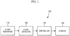
- FIG. 1 is a block diagram illustrating a configuration of an X-ray imaging device.
- the X-ray imaging device or the X-ray imaging apparatus 100 includes an X-ray generator 110 to generate X-rays and radiate the same to an object, an X-ray detector 120 to detect X-rays passing through the object, a controller 130 to evaluate characteristics of the object using the detected X-rays and produce a single energy X-ray image or a multiple energy X-ray image, based on the evaluated results, and a display 140 to display the produced X-ray image.
- the X-ray generator 110 generates X-rays having a predetermined energy level and radiates the same to the object.
- the X-ray generator 110 receives power from a power supply (not shown) and generates X-rays.
- the X-ray energy may be controlled by a supplied tube voltage and the X-ray intensity or dose may be controlled by a tube current and an X-ray exposure time.
- X-rays radiated from the X-ray generator 110 may be monochromatic X-rays or polychromatic X-rays, a configuration in which polychromatic X-rays are radiated from the X-ray generator is described below with reference to exemplary examples, for convenience of description.
- the X-ray generator 110 radiates X-rays having a predetermined energy band, and an energy band of the radiated X-rays is defined by an upper limit and a lower limit.
- X-ray energy may be represented as average energy, maximum energy, energy band or the like.
- X-ray energy is represented by an X-ray energy band or maximum energy of the X-ray energy band.
- the upper limit of the energy band that is, the maximum energy of radiated X-ray is controlled by a level of tube voltage
- energy band lower limit that is, a minimum energy of radiated X-rays is controlled by a filter provided inside or outside the X-ray generator 110.
- the X-ray detector 120 detects X-rays passing through the object and converts the detected X-rays into electrical signals.
- X-rays radiated from the X-ray generator 110 pass through the object and are attenuated.
- An attenuation ratio of X-rays varies depending on characteristics of tissues of an object area, to which the X-rays are radiated, or thickness of the object area, and an amount of detected X-rays varies depending on the inner composition of the object.
- the object is imaged by using the electrical signal of the X-ray detector 120 and a signal output from the X-ray detector 120 is a type of image signal.
- the X-ray detector 120 acquires a plurality of image signals with different energy bands.
- a method of acquiring image signals includes a method including radiating respectively a plurality of X-rays having different energy bands by the X-ray generator 110 and detecting respectively the plurality of X-rays by the X-ray detector 120, and a method including radiating X-rays having a predetermined energy band by the X-ray generator 110 and dividing the X-rays into specific energy bands by the X-ray detector 120.
- the different energy bands may have at least one of upper and lower limits of energy bands which are different from one another.
- the controller 130 analyzes the image signal acquired by the X-ray detector 120 and evaluates characteristics of the object.
- the characteristics of the object include at least one of structures of the tissues constituting the object, ratios of respective tissues and densities of specific tissues, and another characteristic of the object evaluated by the controller 130 may be used as a characteristic of the object so long as it determines an X-ray image which is easy to analyze.
- the controller 130 generates at least one of a single energy X-ray image and a multiple energy X-ray image, based on the evaluation results of the object.
- the single energy X-ray image means an X-ray image which is produced by detecting X-rays having a single energy band
- the multiple energy X-ray image means an X-ray image which is produced by detecting a plurality of X-rays having different energy bands and increasing a contrast between components of the object using the X-rays detected.
- An image signal produced from X-rays having a single energy band exhibits good signal-to-noise ratio (SNR) and a single energy X-ray image thus exhibits superior spatial resolution and contrast.
- SNR signal-to-noise ratio
- the multiple energy X-ray image has a high contrast between tissues and is thus useful for specific tissues such as lesions.
- the controller 130 produces a multiple energy X-ray image with increased contrast between tissues, when the object has a dense tissue having a high ratio of fat tissue to parenchymal tissue, and the controller 130 produces a single energy X-ray image, when the object has a tissue having a high ratio of parenchymal tissue to fat tissue.
- the controller 130 analyzes an image signal acquired by pre-shot and controls imaging conditions such as tube voltage and tube current supplied to the X-ray generator 110 and X-ray exposure time.
- the pre-shot aims at controlling X-ray imaging conditions depending on characteristics of the object prior to main imaging and is performed at X-rays dose decreased by controlling tube current and X-ray exposure time.
- the controller 130 may select a target material (anode) used for X-ray generation in the X-ray generator 110, or a filter used for filtering the generated X-ray.
- the display 140 displays the X-ray image generated by the controller 130 for a user to perform diagnosis by analyzing the image.
- the X-ray imaging device may be used to image the chest, mouth, breasts and various other tissues, organs, or bones of the human body according to an application and the structure of the X-ray imaging device may be slightly changed according to imaging area.
- the X-ray imaging device has no restrictions as to imaging area, for convenience of description, a detailed operation of the mammography X-ray imaging device is described below with reference to an exemplary example.
- FIG. 2 illustrates an overall exterior appearance of an X-ray imaging device to image breast according to an exemplary example.
- FIG. 3 is a sectional view illustrating an internal composition of a breast.
- the X-ray imaging device 100 to image breasts includes a housing 101 to support the X-ray generator 110 and the X-ray detector 120, and a compression paddle 20 to compress the breast.
- a breast is disposed between the X-ray detector 120 and the compression paddle 20, to reduce a thickness of the breast by compression using the compression paddle 20, and X-rays are irradiated using the X-ray generator 110, to perform X-ray imaging.
- the controller 130 controls X-ray imaging conditions depending on breast characteristics and for this purpose, the X-ray imaging device performs pre-shot to evaluate characteristics of the breast.
- the controller 130 analyzes an image signal acquired by pre-shot, estimates or calculates a density of breast and a thickness of compressed breast and determines imaging conditions suitable for characteristics of the object using these properties as analysis factors. Information associated with the thickness of the compressed breast may be acquired from the compression paddle 20.
- the controller 130 may be provided in a workstation or a host device to control an operation of the X-ray imaging device, but a position thereof is not limited.
- the tissues of the breast 50 include fibrous tissue 51 which surrounds the breast periphery and supports the breast shape, fat tissue 52 distributed throughout the breast, a breast gland tissue 53 to produce human milk, and a breast duct tissue 54 to provide a passage for breast milk and the like.
- Tissues associated with production and supply of breast milk, such as the breast gland tissue 53 and the breast duct tissue 54, are referred to as parenchymal tissues of breast.
- the parenchymal tissues have similar lesions, such as tumors, and similar X-ray absorbance. Accordingly, it is difficult to detect lesions from a breast X-ray image in which parenchymal tissues are dense and/or large, and it is relatively easy to detect lesions in a breast X-ray image in which little parenchymal tissue is present.
- the breast 50 when the breast 50 is a dense breast in which parenchymal tissues are dense, a multiple energy X-ray image with an increased contrast between tissues is produced.
- the breast 50 has less density, a single energy X-ray image with a superior signal-to-noise ratio is produced.
- the method for producing a multiple energy X-ray image is divided into irradiation of a plurality of X-rays with different energy bands from the X-ray generator 110 and separation of X-rays detected from the X-ray detector 120 according to respective energy bands.
- FIG. 4 is a block diagram illustrating X-rays imaging device according to an exemplary example in detail.
- the X-ray imaging device 200 radiates X-rays with different energy bands to produce a multiple energy X-ray image and performs pre-shot prior to main imaging.
- the controller 230 includes an image analyzer 231 to analyze the image signal acquired by the X-ray detector 220 and evaluate characteristics of the object, an image controller 232 to determine X-ray imaging conditions depending on characteristics of the object, and an image processor 233 to produce a single energy X-ray image or a multiple energy X-ray image using the image signal acquired by the X-ray detector 220.
- the X-ray generator 210 radiates X-rays having a lower dose, as compared to the main imaging, to perform pre-shot.
- the X-ray detector 220 detects X-rays passing through the object during pre-shot and acquires an image signal of the object.
- pre-shot may be performed by adjusting X-ray dose to about 4 mAs.
- the image analyzer 231 analyzes the image signal acquired by the X-ray detector 220 and evaluates characteristics of the object.
- the image analyzer 220 determines the breast density. As described above with reference to FIG. 3 , when parenchymal tissues of breast are dense and/or large, it is not easy to detect lesions in the breast tissue. A growth or a size degree of parenchymal tissues in the breast is referred to as breast density.
- a breast region is extracted from the image signal acquired by the X-ray detector 220 and a region to be estimated as a parenchymal tissue is extracted from the breast region.
- a ratio of an area of the parenchymal tissue region with respect to a total area of the breast region is calculated to represent the breast density.
- the region corresponding to the parenchymal tissue is estimated as a region which has a high image signal brightness or intensity.
- a predetermined first value is compared with the brightness or intensity of the image signal in each pixel region of the breast. When the brightness or intensity of the image signal exceeds the first value, the corresponding pixel region is estimated to belong to the parenchymal tissue.
- the first value may be predetermined through experimentation, statistics or theoretically.
- the image controller 232 controls main imaging based on characteristics of the object evaluated by the image analyzer 231. Specifically, the image controller 232 determines whether a single energy X-ray image or a multiple energy X-ray image is to be acquired by main imaging, based on characteristics of the object and controls the X-ray generator 210 based on the results. That is, when the characteristic of object corresponds to a single energy X-ray image, the single energy X-ray image is acquired, and when the characteristic of object corresponds to a multiple energy X-ray image, the multiple energy X-ray image is acquired.
- the characteristic of object is determined to correspond to the multiple energy X-ray image
- the characteristic of object is determined to correspond to the single energy X-ray image.
- the second standard value means a standard value which determines that the breast as the object is a dense breast.
- the second value may be predetermined by a designer or a user. For example, when a breast density exceeds 50%, the breast is determined to be a dense breast in accordance with the classification standard of breast imaging reporting and database system (BI-RADS).
- BI-RADS breast imaging reporting and database system
- an exemplary example of the X-ray imaging device 200 is not limited thereto and other standard values may be set through experimentation or theoretically.
- the image controller 232 may control imaging conditions such as tube voltage and tube current supplied to the X-ray generator 210 and X-ray exposure time depending on object characteristics.
- the X-ray generator 210 When the characteristic of object corresponds to a multiple energy X-ray image, the X-ray generator 210 respectively radiates a plurality of X-rays having different energy bands for main imaging.
- the energy bands of radiated X-rays may be set according to type or characteristics of object.
- FIG. 5 is a graph showing energy bands of X-rays radiated from the X-ray imaging device.
- the X-ray generator radiates X-rays with a first energy band E1, X-rays with a second energy band E2 and X-rays with a third energy band E3 and the energy bands may partially overlap one another.
- a tube voltage of about 25 kVp is supplied to the X-ray generator 210 to generate X-rays with a maximum energy E1 max of about 25 keV.
- the X-ray generator 210 adjusts a minimum energy E1 min of the radiated X-rays to about 10 keV using the filter provided inside or outside the device. As a result, X-rays having the first energy band E1 (about 10 to about 25 keV) are emitted.
- a tube voltage of about 35 kVp is supplied to the X-ray generator 210 to generate X-rays having a maximum energy E2 max of about 35 keV.
- the X-ray generator 210 adjusts a minimum energy E2 min of emitted X-rays to about 15 keV using the filter. As a result, X-rays having the second energy band E2 (about 15 to about 35 keV) are emitted.
- a tube voltage of 50 kVp is supplied to the X-ray generator 210 to generate X-rays having a maximum energy E3 max of about 50 keV.
- the X-ray generator 210 adjusts a minimum energy E3 min of emitted X-rays to about 30 keV using the filter. As a result, X-rays having the third energy band E3 (about 30 to about 50 keV) are emitted.
- the X-ray detector 220 detects a plurality of X-rays passing through the object, acquires a plurality of image signals of respective energy bands from the detected X-rays and transmits the image signals to a first image processor 233a.
- the first image processor 233a performs multiple energy image processing on the transmitted image signals to produce a multiple energy X-ray image with an increased contrast between tissues.
- the multiple energy image processing is an image processing method for producing an image having an increased contrast between soft tissues and lesions having similar X-ray absorbance from a plurality of image signals having different energy bands, or an image having an increased contrast of soft tissues and hard tissues (such as bones or calcified materials) and any multiple energy image processing may be used in the X-ray imaging device.
- FIG. 6 is a graph schematically showing variation in attenuation coefficient with respect to individual substances constituting the human body.
- X-ray transmittance is changed depending on characteristics of an object, through which the X-ray passes, and this is defined as an attenuation coefficient.
- FIG. 6 shows variation in attenuation coefficient as a function of X-ray energy with respect to bone, muscle and fat of the human body. As shown in FIG. 6 , bone, muscle and fat exhibit different variations in attenuation coefficient and the difference in attenuation coefficient between substances is changed according to X-ray energy.
- the attenuation coefficient varies between various soft tissues containing fat. Accordingly, by using a plurality of image signals with different energy bands, substances having different attenuation properties may be extracted from one image.
- N N 0 ⁇ e ⁇ ⁇ E T
- Equation 1 may be represented by the following Equation 2.
- N N 0 ⁇ e ⁇ ⁇ 1 E T1 + ⁇ 2 E T2 + ... + ⁇ M E TM
- an image pixel value is determined by dividing both sides by a measurable value N 0 and applying antilogarithm (-log ).
- the pixel value I(E 1 ) may be represented by the following Equation 3.
- Equation 4 is derived based on an ideal monochromatic X-ray image, but a modification of Equation 4 may be used when X-rays having a predetermined energy band image are used.
- the multiple energy X-ray image produced by the first image processor 233a may be a plurality of images separated according to respective substances, an image of only a specific substance, a region in which a ratio difference between substances is out of a normal range is diacritically marked as an abnormal tissue using the images separated according to respective substances, or an image in which the plurality of images are combined and the respective substances are diacritically marked in one image.
- a difference in attenuation coefficient between the substances decreases, as X-ray energy increases, and increases, as X-ray energy decreases. Accordingly, X-rays with a low energy band in which a difference in attenuation coefficient between the substances is great may be used to obtain a breast X-ray image consisting of soft tissues such as parenchymal tissue, fat tissue and fibrous tissue.
- an X-ray image with increased contrast between substances is produced by obtaining image signals regarding energy bands which may be imaged without great limitation of X-ray dose and estimating an image signal regarding a low energy band showing a great difference in attenuation coefficient between the substances from these image signals.
- the produced image is displayed on the display 240 and a user easily detects lesions on an image with an increased contrast ratio.
- the image controller 232 controls the X-ray generator 210 to radiate X-rays having a single energy band to an object, when the characteristic of object corresponds to a single energy X-ray image, that is, the breast is determined not to be a dense breast.
- the X-ray detector 220 detects X-rays passing through the object and acquires an image signal of the object.
- the acquired image signal is transmitted to the second image processor 233b which subjects the image signal to image processing to produce an X-ray image.
- the image processing may include noise removal, edge enhancement or contrast ratio adjustment to produce a single energy X-ray image.
- the second image processor 233b controls gradation and frequency properties of images by gradation processing and frequency processing, improves image quality through spatial frequency processing and realizes objective image enhancement by gradation processing. Details of such image processing are known to those skilled in the art and a detailed explanation thereof will be omitted.
- the produced X-ray image is displayed on the display 240 and a user analyzes the X-ray image with a superior signal-to-noise ratio (SNR) and thereby detects lesions.
- SNR signal-to-noise ratio
- the image signal acquired during pre-shot is analyzed and characteristics of the object are evaluated.
- an image of main imaging may be analyzed and characteristics of the object may be evaluated instead of or in addition to the pre-shot.
- the X-ray generator 210 radiates X-rays with a first energy band to an object and the X-ray detector 220 detects X-rays passing through the object to acquire an image signal.
- the first energy band corresponds to an energy band to produce a single energy X-ray image and is set by pre-shot or according to object type (chest, abdomen, breast and other skeletons) without pre-shot. For example, when chest is used as the imaging region, a high energy band having a maximum energy of about 140 keV is set at a first energy band and, when a breast is used as the imaging region, a low energy band having a maximum energy of about 30 keV is set at the first energy band.
- the acquired image signal is transmitted to the image analyzer 231 and the image analyzer 231 analyzes the image signal and evaluates characteristics of the object.
- a method for evaluating characteristics of the object is described above.
- the image controller 232 controls the X-ray generator 210 to radiate X-rays with a second energy band to an nth energy (n ⁇ 2, n is an integer) band, the X-ray detector 220 detects the X-rays and converts the x-rays into image signals.
- n may be set depending on characteristics of the object and an order of n is not related to an energy level.
- n when imaging the chest, n is set at 2 and X-rays with an energy band having a maximum energy of about 70 keV are radiated, and when imaging the breast, n is set at 2 and X-rays with an energy band having a maximum energy of about 50 keV are radiated.
- High energy and low energy are relative concepts. That is, when chest is imaged, X-rays with an energy band having a maximum energy of about 70 keV are X-rays with a low energy band, and when breast is imaged, an X-ray with an energy band having a maximum energy of about 50 keV is an X-ray with a high energy band.
- the converted image signal is transmitted to the first image processor 233a which performs multiple energy image processing on an image signal corresponding to the first energy band and an image signal corresponding to the remaining energy band, produces a multiple energy X-ray image with increased contrast between tissues and displays the image on the display 240.
- a first energy X-ray signal is transmitted to the second image processor 233b, and, thus, a single energy X-ray image is generated without further radiation of X-rays.
- An exemplary example using a method for acquiring a multiple energy X-ray image by respectively radiating a plurality of X-rays from the X-ray generator is described above.
- an exemplary example using a method for separating X-rays according to respective energy bands in the X-ray detector is described below.
- FIG. 7 is a block diagram illustrating a configuration of an X-ray imaging device according to an exemplary example.
- the X-ray imaging device 300 includes an X-ray generator 310 to generate X-rays, an X-ray detector 320 to detect the X-ray passing through the object, a controller 330 to evaluate characteristics of the object using the detected X-rays and produce a single energy X-ray image or a multiple energy X-ray image, based on the evaluated results, and a display 340 to display the X-ray image.
- the X-ray generator 310 may perform pre-shot by radiating a reduced dose of X-rays.
- the X-rays radiated from the X-ray generator 310 may be a wide band X-ray including a wide energy band which is an energy band including a plurality of different single energy bands.
- the energy band of the radiated X-ray may be changed depending on object type. For example, when imaging the chest X-rays having an energy band of about 10 to about 140 keV may be radiated, and when imaging the breast, X-rays having an energy band of about 10 to about 50 keV may be radiated.
- the radiated X-rays pass through the object and are detected by the X-ray detector 320.
- the X-ray detector 320 includes a photon counting detector (PCD) 322 and separates the detected X-rays according to energy band.
- PCD photon counting detector
- FIG. 8 a circuit view of the pixel area of the PCD is shown.
- the PCD 322 is divided into a sensor region 151 to detect X-rays and a readout circuit region 152, and the sensor region may include a light-receiving device such as photodiode.
- the two regions may be connected to each other by bonding such as bump bonding.
- the electrons or holes moved based on the electric field are input to the readout circuit region 152 through bump bonding, and an amplifier 52a of the readout circuit region 152 charges an input charge generated from one photon and outputs a voltage signal corresponding thereto.
- the comparator 52b compares the input voltage signal with the threshold voltage, outputs the comparison results as pulses and input the same to the counter 52c.
- the counter 52c counts the number of output pulses of the comparator per unit time and measures X-ray intensity (represented as the number of photons) with a predetermined energy band among incident X-rays.
- the readout circuit region 52 may include three comparators corresponding to the energy bands.
- a signal output from the X-ray detector 320 is an X-ray image signal of each energy band.
- the X-ray image signal includes information associated with the number of photons present in each pixel.
- the signals output from the X-ray detector 320 are a first energy image signal, a second energy image signal and a third energy image signal.
- the image signals may be output from the entire energy band which is not separated.
- the X-ray detector 320 may output an image signal in the entire energy band, instead of separating X-rays according to energy bands.
- the controller 330 includes an image analyzer 331 to analyze an image signal and evaluate characteristics of the object, an image controller 332 to control an X-ray generator 310 or X-ray detector 320, based on the analysis results of the image analyzer 331, and an image processor 333 to produce a multiple energy X-ray image or a single energy X-ray image.
- the image analyzer 331 analyzes at least one of image signals output from the X-ray detector 320 and evaluates object characteristics.
- the image signal used for analysis may be the first energy image signal, the second energy image signal, the third energy image signal or any image signal of the entire energy band.
- the image analyzer 331 evaluates tissue properties of the object and, in an exemplary example, the image analyzer 331 determines breast density. Operation of the image analyzer 331 is described in detail above and a detailed description thereof is thus omitted.
- the image controller 332 determines whether the characteristic of object corresponds to a multiple energy X-ray image or a single energy X-ray image, based on the determination results of the image analyzer 331, controls the X-ray generator 310 or the X-ray detector 320 based on the result and begins main imaging.
- a broadband X-ray having a greater dose than X-rays radiated from the X-ray generator 310 during pre-shot is radiated to the object and the X-ray detector 320 detects X-rays passing through the object.
- the energy band of radiated X-rays may be the same as the energy band of X-ray radiated during pre-shot and may be newly set, based on characteristics of the object.
- the X-ray detector 320 detects the X-ray, converts the same into a voltage signal and separates the converted voltage signal according to predetermined energy bands.
- the separated energy band may be set by the image controller 332 or the user according to object type, or by the image controller 332 depending on object characteristics analyzed in the image analyzer 331.
- Image signals of the image are acquired according to individual energy bands and the acquired image signals are transmitted to the first image processor 333a.
- the first image processor 333a performs multiple energy image processing on the image signals according to individual energy bands, produces a multiple energy X-ray image with an improved contrast between tissues and displays the image on the display 340.
- the image processing operation of the first image processor 333a is described in detail above.
- characteristics of the object are evaluated by analyzing image signals acquired by pre-shot, but in another exemplary example, characteristics of the object may be evaluated by analyzing image signals acquired by main imaging.
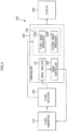
- FIG. 9 is a block diagram illustrating an X-ray imaging device according to an exemplary embodiment.
- X-ray dose may be decreased even during main imaging, an energy band suitable for characteristics of an object may be set once after X-rays are radiated and pre-shot may be thus not performed.
- the X-ray imaging device 400 according to the exemplary embodiment of FIG. 9 analyzes image signals acquired during main imaging, regardless of performance of pre-shot.
- the X-ray generator 410 radiates a broadband X-ray including a plurality of energy bands to an object. X-rays passing through the object are converted into an electric signal by the X-ray detector 420 and the X-ray detector 420 including the PCD separates the converted electric signals into individual energy bands predetermined according to object type, or separates only an energy band used for determination of object characteristics or acquires an image signal of the entire energy band.
- the image analyzer 431 of the controller 430 analyzes image signals of the object and evaluates characteristics of the object.
- the image signal used for evaluation of characteristics of the object is one of image signals converted by the X-ray detector 420.
- the X-ray detector 420 separates the X-ray into predetermined individual energy bands, one of the separated energy bands may be selected and analyzed. For example, when imaging the breast, an image signal corresponding to a low energy band may be analyzed, and when imaging the chest, an image signal corresponding to a high energy band may be analyzed.
- the evaluation of characteristics of the object is described in detail above.
- the image controller 432 determines whether the characteristic of object determined in the image analyzer 431 corresponds to a multiple energy X-ray image or a single energy X-ray image.
- the image signals are stored in a memory (not shown) provided in the X-ray detector 420 or the controller 430.
- the memory transmits the image signals to a first image processor 433a, and the first image processor 433a produces a multiple energy X-ray image with improved contrast between tissues through multiple energy image processing.
- the memory transmits one of the image signals to the second image processor 433b.
- the image signal transmitted to the second image processor 433b may be determined depending on type or characteristics of the object and may be an image signal used for the image analyzer 431.
- the X-ray detector 420 separates only an energy band used for evaluation of characteristics of the object
- the characteristic of object corresponds to a multiple energy X-ray image
- X-rays are separated at a not-separated band among the energy bands
- image signals at respective energy bands and image signals used for evaluation of characteristics of the object are transmitted to the first image processor 433a.
- the image signal used for evaluation of characteristics of the object is transmitted to the second image processor 433b.
- the image X-ray detector 420 converts the entire energy band of X-rays into an image signal
- the image X-ray detector acquires image signals of respective energy bands and transmits the same to the first image processor 433a.
- the image X-ray detector transmits the entire energy band of image signal to the second image processor 433b, or the X-ray detector 420 acquires an image signal of the single energy band determined according to type or characteristic of object and transmits the same to the second image processor 433b.
- the energy bands separated by the X-ray detector 420 or the single energy band may be predetermined by the user or the imaging controller 432 depending on type or thickness of object, or by the imaging controller 432 depending on object characteristics evaluated by the image analyzer 431.
- both a multiple energy X-ray image and a single energy X-ray image may be produced and displayed on a display 440.
- FIG. 10 is a flowchart illustrating a method for producing an X-ray image according to an exemplary example.
- an image signal acquired during pre-shot is analyzed, in a method for radiating X-rays several times in order to acquire a multiple energy X-ray image.
- X-rays are radiated to an object (operation 611).
- the radiated X-ray dose is decreased by decreasing tube current and exposure time, as compared to main imaging and the X-ray energy band may be suitably set according to the object.
- a high energy band of about 120 to about 140 keV may be set and when imaging the breast, a low energy band of about 10 to about 30 keV may be set.
- X-rays passing through the object are detected.
- An image signal is acquired (operation 613).
- X-rays passing through the object are detected at each pixel by the X-ray detector and the detected X-rays are converted into an electric signal.
- the electric signal may be an analog signal or a digital signal. When all the electric signals of respective pixels are combined, one image of the object may be acquired and the electric signal corresponds to an image signal of the object.
- the acquired image signal is analyzed and object characteristics are evaluated (operation 614).
- the object characteristics include characteristics affecting image analysis and are associated with inner structures of the object, as for example, at least one of tissue composition, ratios of respective tissues and a ratio of specific tissue of the object.
- the breast density is determined.
- the breast density may be represented by a ratio of a parenchymal tissue with respect to the total breast tissue, and a reference value, providing an estimation basis of the parenchymal tissue, may be predetermined according to experiments, statistics or theory.
- a plurality of X-rays having different energy bands are respectively radiated to the object (operation 616).
- the energy band of the radiated X-rays and the number of X-ray irradiation may be predetermined depending on object type or may be set depending on object characteristics evaluated by analyzing image signals.
- the radiated X-ray pass through the object and a plurality of X-rays passing through the object are detected and are converted into a plurality of image signals (operation 617).
- the flowchart shows that the X-rays are radiated and then detected. This disclosure is given for convenience of description only. In an exemplary example, a first X-ray is radiated, the following X-ray is radiated, and the X-rays are then detected.
- the image signals are subjected to multiple energy image processing to produce a multiple energy X-ray image (operation 618).
- the multiple energy image processing enables one image with an improved contrast between tissues to be acquired from the image signals, as described in detail above.
- the produced multiple energy X-ray image is displayed on the display (operation 619).
- a user analyzes dense breast using a multiple energy X-ray image with an improved contrast between tissues and thereby efficiently determines presence of lesions.
- the characteristic of object does not correspond to a multiple energy X-ray image (NO)
- the characteristic of the object corresponds to a single energy X-ray image
- a single energy X-ray image is produced by performing main imaging.
- X-rays having a single energy band are radiated to an object (operation 621).
- An energy of the radiated X-rays may be the same as an energy of X-rays radiated during pre-shot, but X-ray dose may be increased by increasing tube current and exposure time, as compared to pre-shot.
- the X-ray passing through the object is detected (operation 622) and an image signal is acquired (operation 623).
- the converted image signal is subjected to image processing to produce a single energy X-ray image (operation 624).
- the image processing means image processing generally used for generation of the X-ray image and a detailed explanation thereof is thus omitted.
- the obtained image is displayed on the display (operation 625).
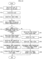
- FIG. 11 is a flowchart illustrating a method for producing an X-ray image according to an exemplary example.
- the pre-shot is not performed.
- an X-ray with a first energy band is radiated to the object (operation 631).
- the first energy band X-ray may be used for generation of the single energy X-ray image and a first level of energy may be changed depending on object type.
- the X-ray passing through the object is detected (operation 632), and a first energy image signal of the object is acquired from the detected X-ray (operation 633).
- the first energy image signal corresponds to an image signal indicating a general single energy X-ray image.
- the first energy image signal is analyzed and characteristics of the object are evaluated (operation 634).
- the evaluation of object characteristics is described with reference to FIG. 8 above and a detailed explanation thereof is thus omitted.
- the characteristic of object corresponds to a multiple energy X-ray image (operation 635), as for example, when the tissues of the object are dense and/or an image with an improved contrast between the tissues is needed, and a multiple energy X-ray image of the object is produced.
- 2 nd to n th energy (n ⁇ 2, in which n is an integer) bands of X-rays are radiated to the object (operation 636).
- the 2 nd to n th energy bands are different energy bands and are different from the first energy band.
- X-rays of different energy bands are sequentially radiated from the X-ray generator and the 1 st to n th energy bands may indicate an X-ray irradiation order and may be unrelated to energy levels.
- the energy level of X-rays and the number (n) of different energy bands may be predetermined depending on object type and may be set depending on object characteristics evaluated by analyzing image signals.
- the 2 nd to n th energies passing through the object are detected (operation 637) and 2 nd to n th energy image signals of the object are acquired from the detected X-rays (operation 638).
- the flowchart discloses that 2 nd to n th energy X-rays are radiated and then detected. This disclosure is given only for convenience of description. In the exemplary example, a second energy X-ray is radiated, the following X-ray is radiated and the X-rays are then detected.
- the 1 st to n th energy image signals are subjected to multiple energy image processing to produce a multiple energy X-ray image (operation 639), and the produced image is displayed on the display (operation 640).
- the first energy image signal is the image signal used for evaluation of characteristics of the object.
- the acquired first energy image signal is subjected to image processing to produce a first energy X-ray image (operation 641), and the image is displayed on the display (operation 640).
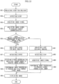
- FIG. 12 is a flowchart illustrating a method for producing an X-ray image according to an exemplary example.
- the pre-shot is performed.
- X-rays are radiated to the object, for pre-shot (operation 651).
- the radiated X-ray has a dose or irradiation amount which is decreased by decreasing a tube current and an exposure time, and the X-rays may have an energy band set according to object type and may be a broadband X-ray including a plurality of energy bands.
- the X-ray passing through the object is detected (operation 652) and an image signal of the object is acquired from the detected X-ray (operation 653).
- an energy band suitable for the object may be separated during acquisition of an appropriate image signal. For example, when imaging the breast, an image signal of an energy band of about 30 keV or less is acquired.
- An image signal of the object is analyzed and characteristics of the object are evaluated (operation 654).
- the evaluation of characteristics of the object is described in detail above.
- the determined characteristic of the object corresponds to a multiple energy X-ray image (YES), as for example, when the tissues of the object are dense and/or an image with improved contrast between tissues is needed, and a multiple energy X-ray image of the object is produced.
- YES multiple energy X-ray image
- X-rays are radiated to the object to begin main imaging (operation 656).
- the radiated X-rays may be polychromatic X-rays having a predetermined energy band and include both a low energy band and a high energy band. For example, when imaging the breast, X-rays with a 10-50 keV band may be radiated.
- the X-rays passing through the object are detected (operation 657) and the detected X-rays are divided according to individual energy bands to acquire a plurality of image signals (operation 658).
- the separation of the energy bands may be predetermined depending on object type or be set in consideration of object characteristics.
- the image signals are image signals of individual energy bands.
- the image signals are subjected to multiple energy image processing to produce a multiple energy X-ray image with improved contrast between tissues (operation 659), and the produced image is displayed on the display (operation 660).
- X-rays are radiated to the object to begin main imaging (operation 661).
- An X-ray of a specific energy band set according to type or properties of the object may be radiated and a broadband X-ray including the specific energy band may be radiated.
- the X-ray passing through the object is detected (operation 662) and an image signal of the object is acquired from the detected X-ray (operation 663).
- the radiated X-ray is a broadband X-ray having a specific energy band
- an X-ray with a specific energy level set according to type or characteristic of object is separated from the detected broadband X-ray and an image signal corresponding to the corresponding energy level may be acquired.
- the acquired image signal is subjected to image processing to produce a single energy X-ray image (operation 664) and the produced image is displayed on the display (operation 660).
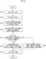
- FIG. 13 is a flowchart illustrating a method for producing an X-ray image according to an exemplary example.
- the pre-shot is not performed.
- an X-ray is radiated to the object (operation 671).
- the radiated X-ray is an X-ray for main imaging which includes a plurality of energy bands set depending on the object.
- the X-ray passing through the object is detected (operation 672) and an image signal of the object is acquired from the detected X-ray (operation 673).
- Characteristics of the object are evaluated by analyzing image signals (operation 674). The evaluation of object characteristics is described above.
- the characteristic of the object corresponds to a multiple energy X-ray image (YES), as for example, when the tissues of the object are dense and/or an image with improved contrast between tissues is needed, and a multiple energy X-ray image of the object is produced.
- YES multiple energy X-ray image
- the X-rays detected in (operation 672) are divided according to individual energy bands and a plurality of image signals corresponding to the energy bands are acquired (operation 676).
- the divided energy bands may be set depending on type or characteristics of the object.
- the acquired image signals are subjected to multiple energy image processing to produce a multiple energy X-ray image (operation 677) and the produced image is displayed on the display (operation 678).
- the acquired image signal acquired is subjected to image processing to produce a single energy X-ray image (operation 679). That is, an X-ray image corresponding to the entire energy band of the detected X-ray may be produced.
- an X-ray with a desired energy band is extracted, an image signal is acquired from the extracted X-ray and production of a single energy X-ray image from the image signal is possible. For example, when imaging the breast, an X-ray with a low energy band (10-30 keV) may be extracted and when imaging the chest, an X-ray with a high energy band (120-140 keV) may be extracted.
- the produced image is displayed on the display (operation 678) and the user analyzes a single energy X-ray image with superior image quality and thereby detects lesions.
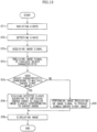
- FIG. 14 is a flowchart illustrating a method for producing an X-ray image according to an exemplary example.
- the pre-shot is not performed and X-rays are separated into individual energy bands before evaluation of object characteristics.
- X-rays are radiated to an object (operation 681).
- the radiated X-rays are used for main imaging and include a plurality of energy bands predetermined depending on the object.
- the X-rays passing through the object are detected (operation 682) and the detected X-rays are divided according to individual energy bands to acquire a plurality of image signals (operation 683). An image signal of the entire energy band may be acquired.
- the analyzed image signal may be an image signal of the entire energy band, an image signal of a low energy band or an image signal of a high energy band according to the object.
- the characteristic of the object corresponds to a multiple energy X-ray image (YES), as for example, the tissues of the object are dense and/or an image with improved contrast between tissues is needed, and a multiple energy X-ray image of the object is produced.
- YES multiple energy X-ray image
- the acquired image signals are subjected to multiple energy image processing to produce a multiple energy X-ray image (operation 686) and the produced image is displayed on the display (operation 687).
- the characteristic of object does not correspond to a multiple energy X-ray image (NO), as for example, the tissues of the object are not dense and/or easy detection of lesions is possible with a single energy X-ray image, a single energy X-ray image of the object is produced.
- NO multiple energy X-ray image
- one of the acquired image signals is subjected to image processing to produce a single energy X-ray image (operation 688) and the produced image is displayed on the display (operation 687).
- At least one of a single energy X-ray image and a multiple energy X-ray image is produced according to tissue characteristics of the object and efficient image analysis is thus possible.
Landscapes
- Health & Medical Sciences (AREA)
- Life Sciences & Earth Sciences (AREA)
- Engineering & Computer Science (AREA)
- Medical Informatics (AREA)
- Public Health (AREA)
- Pathology (AREA)
- General Health & Medical Sciences (AREA)
- Biomedical Technology (AREA)
- Surgery (AREA)
- Radiology & Medical Imaging (AREA)
- Nuclear Medicine, Radiotherapy & Molecular Imaging (AREA)
- Heart & Thoracic Surgery (AREA)
- Molecular Biology (AREA)
- Physics & Mathematics (AREA)
- Animal Behavior & Ethology (AREA)
- High Energy & Nuclear Physics (AREA)
- Biophysics (AREA)
- Veterinary Medicine (AREA)
- Optics & Photonics (AREA)
- Computer Vision & Pattern Recognition (AREA)
- Physiology (AREA)
- Dentistry (AREA)
- Human Computer Interaction (AREA)
- Oral & Maxillofacial Surgery (AREA)
- Data Mining & Analysis (AREA)
- Databases & Information Systems (AREA)
- Epidemiology (AREA)
- Primary Health Care (AREA)
- Apparatus For Radiation Diagnosis (AREA)
Claims (12)
- Röntgenaufnahmeeinrichtung, umfassend:einen Röntgengenerator (110), der dazu konfiguriert ist, Röntgenstrahlen zu erzeugen und auf ein Objekt zu strahlen;einen Röntgendetektor (120), der dazu konfiguriert ist, die Röntgenstrahlen, die das Objekt durchdrungen haben, zu detektieren und ein Bildsignal des Objekts zu erfassen;wobei der Röntgendetektor dazu konfiguriert ist, eine Vielzahl von Bildsignalen gemäß einer Vielzahl von individuellen Energiebändern zu erfassen;einen Speicher zum Speichern der Vielzahl von Bildsignalen; undeine Steuerung (130), die dazu konfiguriert ist, eine Eigenschaft des Objekts basierend auf einem der Bildsignale auszuwerten und ein Einzelenergie-Röntgenbild basierend auf einem der im Speicher gespeicherten Bildsignale und ein Mehrfachenergie-Röntgenbild basierend auf der Vielzahl von im Speicher gespeicherten Bildsignalen zu erzeugen,wobei das Bildsignal, auf dem das Einzelenergiebild basiert, basierend auf dem Auswertungsergebnis der Eigenschaften des Objekts bestimmt wird;wobei die Röntgenaufnahmeeinrichtung ferner eine Anzeige (140) umfasst und sowohl das Mehrfachenergie-Röntgenbild als auch das Einzel-Röntgenbild auf der Anzeige produziert und angezeigt werden; undwobei der Röntgengenerator dazu konfiguriert ist, die Röntgenstrahlen mit einem Energieband abzustrahlen, das gemäß einem Typ oder der Eigenschaft des Objekts festgelegt ist.
- Röntgenaufnahmeeinrichtung nach Anspruch 1, wobei die Steuerung so konfiguriert ist, dass sie die Anzeige steuert, um das Einzelenergie-Röntgenbild und das Mehrfachenergie-Röntgenbild auf der Anzeige anzuzeigen.
- Röntgenaufnahmeeinrichtung nach Anspruch 1 oder 2, wobei die Eigenschaft mindestens eines von einer Struktur der inneren Gewebe des Objekts, einem Verhältnis der jeweiligen inneren Gewebe und einer Dichte eines spezifischen inneren Gewebes umfasst.
- Röntgenaufnahmeeinrichtung nach einem der Ansprüche 1 bis 3, wobei der Röntgengenerator so konfiguriert ist, dass er die Röntgenstrahlen für eine Voraufnahme abstrahlt, und
die Steuerung so konfiguriert ist, dass sie die Eigenschaft des Objekts basierend auf dem Bildsignal bestimmt, das anhand der für die Voraufnahme abgestrahlten Röntgenstrahlen erfasst wurde. - Röntgenaufnahmeeinrichtung nach einem der Ansprüche 1 bis 4, wobei die Röntgensteuerung so konfiguriert ist, dass sie die Eigenschaft des Objekts basierend auf dem Bildsignal auswertet, das zum Erzeugen des Einzelenergie-Röntgenbildes verwendet wird.
- Röntgenaufnahmeeinrichtung nach einem der Ansprüche 1 bis 5, wobei die individuellen Energiebänder in Abhängigkeit von einem Typ oder einer Dicke des Objekts bestimmt werden.
- Röntgenaufnahmeeinrichtung nach Anspruch 6, wobei der Typ des Objekts einem von Brustkorb, Abdomen, Brust und Skelett entspricht.
- Röntgenaufnahmeeinrichtung nach Anspruch 1 bis 5, wobei die individuellen Energiebänder basierend auf Objekteigenschaften bestimmt werden.
- Röntgenaufnahmeeinrichtung nach Anspruch 8, wobei die Objekteigenschaften mindestens eines von einer Gewebezusammensetzung, Verhältnissen der jeweiligen Gewebe und einem Verhältnis eines spezifischen Gewebes des Objekts beinhalten.
- Röntgenaufnahmeeinrichtung nach Anspruch 9, wobei eine Region, in der ein Verhältnisunterschied zwischen Substanzen außerhalb eines normalen Bereichs liegt, unter Verwendung von Bildern, die gemäß jeweiligen Substanzen getrennt sind, diakritisch als abnormales Gewebe markiert wird.
- Röntgenaufnahmeeinrichtung nach einem der Ansprüche 1 bis 10, wobei die Steuerung ferner so konfiguriert ist, dass sie Bildsignale mit nicht aufgenommenen Energiebändern aus der Vielzahl von Bildsignalen, die der Vielzahl von Energiebändern entsprechen, erfasst.
- Röntgenaufnahmeeinrichtung nach einem der Ansprüche 1 bis 11, wobei die Mehrfachenergie-Röntgenbilder ein Bild mit erhöhtem Kontrast zwischen Substanzen des Objekts umfassen.
Applications Claiming Priority (2)
| Application Number | Priority Date | Filing Date | Title |
|---|---|---|---|
| KR20120098185A KR101479212B1 (ko) | 2012-09-05 | 2012-09-05 | 엑스선 영상 장치 및 엑스선 영상 생성 방법 |
| EP13183170.3A EP2705795B2 (de) | 2012-09-05 | 2013-09-05 | Röntgenaufnahmevorrichtung und Röntgenaufnahmeerzeugungsverfahren |
Related Parent Applications (2)
| Application Number | Title | Priority Date | Filing Date |
|---|---|---|---|
| EP13183170.3A Division-Into EP2705795B2 (de) | 2012-09-05 | 2013-09-05 | Röntgenaufnahmevorrichtung und Röntgenaufnahmeerzeugungsverfahren |
| EP13183170.3A Division EP2705795B2 (de) | 2012-09-05 | 2013-09-05 | Röntgenaufnahmevorrichtung und Röntgenaufnahmeerzeugungsverfahren |
Publications (3)
| Publication Number | Publication Date |
|---|---|
| EP3269307A1 EP3269307A1 (de) | 2018-01-17 |
| EP3269307C0 EP3269307C0 (de) | 2024-10-30 |
| EP3269307B1 true EP3269307B1 (de) | 2024-10-30 |
Family
ID=49212568
Family Applications (2)
| Application Number | Title | Priority Date | Filing Date |
|---|---|---|---|
| EP13183170.3A Active EP2705795B2 (de) | 2012-09-05 | 2013-09-05 | Röntgenaufnahmevorrichtung und Röntgenaufnahmeerzeugungsverfahren |
| EP17185289.0A Active EP3269307B1 (de) | 2012-09-05 | 2013-09-05 | Röntgenaufnahmevorrichtung und röntgenaufnahmeerzeugungsverfahren |
Family Applications Before (1)
| Application Number | Title | Priority Date | Filing Date |
|---|---|---|---|
| EP13183170.3A Active EP2705795B2 (de) | 2012-09-05 | 2013-09-05 | Röntgenaufnahmevorrichtung und Röntgenaufnahmeerzeugungsverfahren |
Country Status (5)
| Country | Link |
|---|---|
| US (3) | US9492132B2 (de) |
| EP (2) | EP2705795B2 (de) |
| JP (2) | JP6234740B2 (de) |
| KR (1) | KR101479212B1 (de) |
| CN (2) | CN103654810B (de) |
Families Citing this family (44)
| Publication number | Priority date | Publication date | Assignee | Title |
|---|---|---|---|---|
| WO2013078476A1 (en) | 2011-11-27 | 2013-05-30 | Hologic, Inc. | System and method for generating a 2d image using mammography and/or tomosynthesis image data |
| WO2007095330A2 (en) | 2006-02-15 | 2007-08-23 | Hologic Inc | Breast biopsy and needle localization using tomosynthesis systems |
| CN102481146B (zh) | 2009-10-08 | 2016-08-17 | 霍罗吉克公司 | 乳房的穿刺活检系统及其使用方法 |
| US20120133600A1 (en) | 2010-11-26 | 2012-05-31 | Hologic, Inc. | User interface for medical image review workstation |
| JP6057922B2 (ja) | 2011-03-08 | 2017-01-11 | ホロジック, インコーポレイテッドHologic, Inc. | スクリーニング、診断及び生検のための二重エネルギー及び/又は造影強化乳房撮像のためのシステム及び方法 |
| WO2013123091A1 (en) | 2012-02-13 | 2013-08-22 | Hologic, Inc. | System and method for navigating a tomosynthesis stack using synthesized image data |
| KR101479212B1 (ko) | 2012-09-05 | 2015-01-06 | 삼성전자 주식회사 | 엑스선 영상 장치 및 엑스선 영상 생성 방법 |
| WO2014151646A1 (en) | 2013-03-15 | 2014-09-25 | Hologic Inc. | Tomosynthesis-guided biopsy in prone |
| US10624598B2 (en) | 2013-03-15 | 2020-04-21 | Hologic, Inc. | System and method for navigating a tomosynthesis stack including automatic focusing |
| JP6305692B2 (ja) * | 2013-05-28 | 2018-04-04 | キヤノンメディカルシステムズ株式会社 | X線診断装置 |
| JP2015024097A (ja) * | 2013-07-29 | 2015-02-05 | 株式会社ジョブ | 低エネルギx線画像形成装置及びその画像の形成方法 |
| EP3646798B1 (de) * | 2013-10-24 | 2023-09-27 | Hologic, Inc. | System und methode zur röntgengestützen brust biopsie |
| EP2871496B1 (de) * | 2013-11-12 | 2020-01-01 | Samsung Electronics Co., Ltd | Strahlungsdetektor und Computertomografievorrichtung damit |
| US10111631B2 (en) | 2014-02-28 | 2018-10-30 | Hologic, Inc. | System and method for generating and displaying tomosynthesis image slabs |
| KR101606746B1 (ko) * | 2014-03-14 | 2016-03-28 | 주식회사 레이언스 | 디지털 엑스레이 영상 시스템, 엑스레이 조사 조절 장치 및 그 방법 |
| US9615803B2 (en) | 2014-06-16 | 2017-04-11 | General Electric Company | System and method for determining X-ray exposure parameters |
| US9610057B2 (en) | 2014-06-16 | 2017-04-04 | General Electric Company | System and method for determining X-ray exposure parameters |
| US20180132810A1 (en) * | 2015-06-09 | 2018-05-17 | The Board Of Trustees Of The Leland Stanford Junior University | System for determining tissue density values using polychromatic x-ray absorptiometry |
| DE102016206071B4 (de) * | 2016-04-12 | 2018-11-15 | Siemens Healthcare Gmbh | Verfahren und Röntgenbildgebungsgerät zur automatischen Regelung der Belichtung bei einer Röntgenbildgebung |
| KR101860145B1 (ko) * | 2016-12-26 | 2018-06-27 | 연세대학교 원주산학협력단 | 광자계수기반 디지털 단층영상합성 장치, 시스템에서의 이중에너지 영상화방법 및 이를 이용한 시스템 |
| CN110621233B (zh) | 2017-03-30 | 2023-12-12 | 豪洛捷公司 | 用于处理乳房组织图像数据的方法 |
| EP3600047A1 (de) | 2017-03-30 | 2020-02-05 | Hologic, Inc. | System und verfahren zur hierarchischen mehrstufigen merkmalsbildsynthese und -darstellung |
| CN110662489B (zh) | 2017-03-30 | 2024-08-02 | 豪洛捷公司 | 用于靶向对象增强以生成合成乳房组织图像的系统和方法 |
| WO2018236565A1 (en) | 2017-06-20 | 2018-12-27 | Hologic, Inc. | METHOD AND SYSTEM FOR MEDICAL IMAGING WITH DYNAMIC SELF-LEARNING |
| EP3467771A1 (de) * | 2017-10-05 | 2019-04-10 | Koninklijke Philips N.V. | Bildmerkmalannotation in der diagnostischen bildgebung |
| US10779791B2 (en) * | 2018-03-16 | 2020-09-22 | General Electric Company | System and method for mobile X-ray imaging |
| EP3787520B1 (de) | 2018-05-04 | 2024-09-25 | Hologic, Inc. | Biopsienadelvisualisierung |
| US12121304B2 (en) | 2018-05-04 | 2024-10-22 | Hologic, Inc. | Introducer and localization wire visualization |
| JP6893491B2 (ja) * | 2018-06-08 | 2021-06-23 | 富士フイルム株式会社 | 画像処理装置、放射線画像撮影システム、画像処理方法、及び画像処理プログラム |
| CN112804944B (zh) | 2018-09-24 | 2024-07-23 | 豪洛捷公司 | 乳房映射和异常定位 |
| JP7098813B2 (ja) * | 2019-02-28 | 2022-07-11 | 富士フイルム株式会社 | 放射線画像処理装置及びプログラム |
| US11883206B2 (en) | 2019-07-29 | 2024-01-30 | Hologic, Inc. | Personalized breast imaging system |
| EP4035176A1 (de) | 2019-09-27 | 2022-08-03 | Hologic, Inc. | Ki-system zur vorhersage der befundungszeit und des befundungsaufwands für die rekonstruktion von 2d/3d-brustbildern |
| AU2021241536A1 (en) | 2020-03-27 | 2022-08-18 | Hologic, Inc. | Systems and methods for identifying regions of interest in multiple imaging modalities |
| US11481038B2 (en) | 2020-03-27 | 2022-10-25 | Hologic, Inc. | Gesture recognition in controlling medical hardware or software |
| JP2023519878A (ja) | 2020-03-27 | 2023-05-15 | ホロジック, インコーポレイテッド | 複数のイメージングモダリティにおける関心領域を相関させるためのシステムおよび方法 |
| CN113038024B (zh) * | 2020-04-16 | 2022-12-23 | 北京纳米维景科技有限公司 | 一种图像校正方法 |
| WO2022060553A1 (en) * | 2020-09-15 | 2022-03-24 | Hologic, Inc. | Systems and methods for determining performance of a breast compression paddle |
| US20220164951A1 (en) | 2020-11-20 | 2022-05-26 | Hologic, Inc. | Systems and methods for using ai to identify regions of interest in medical images |
| JP7740950B2 (ja) * | 2021-10-06 | 2025-09-17 | キヤノンメディカルシステムズ株式会社 | X線画像処理装置、x線診断装置、方法及びプログラム |
| US12254586B2 (en) | 2021-10-25 | 2025-03-18 | Hologic, Inc. | Auto-focus tool for multimodality image review |
| IL313196A (en) | 2021-11-29 | 2024-07-01 | Hologic Inc | Systems and methods for correlating objects of interest |
| KR102760999B1 (ko) | 2022-04-11 | 2025-02-03 | 주식회사 디알텍 | 엑스선 촬영 장치 및 이를 이용하는 엑스선 촬영 방법 |
| EP4548851A1 (de) * | 2023-11-02 | 2025-05-07 | Koninklijke Philips N.V. | Spektralrettung für kontrastierte ct-untersuchungen |
Family Cites Families (38)
| Publication number | Priority date | Publication date | Assignee | Title |
|---|---|---|---|---|
| DE4330787A1 (de) † | 1993-09-10 | 1995-03-23 | Siemens Ag | Verfahren zum Betrieb eines Röntgenbelichtungsautomaten |
| US5748705A (en) * | 1993-11-22 | 1998-05-05 | Hologic Inc. | X-ray bone densitometry |
| CA2184237A1 (en) | 1995-09-08 | 1997-03-09 | Jay A. Stein | X-ray bone densitometry |
| US6683934B1 (en) † | 2000-06-05 | 2004-01-27 | General Electric Company | Dual energy x-ray imaging system and method for radiography and mammography |
| US6501819B2 (en) * | 2000-12-18 | 2002-12-31 | Ge Medical Systems Global Technology Company, Llc | Medical diagnostic method and apparatus to control dual energy exposure techniques based on image information |
| US7263214B2 (en) † | 2002-05-15 | 2007-08-28 | Ge Medical Systems Global Technology Company Llc | Computer aided diagnosis from multiple energy images |
| US7295691B2 (en) * | 2002-05-15 | 2007-11-13 | Ge Medical Systems Global Technology Company, Llc | Computer aided diagnosis of an image set |
| US6813333B2 (en) | 2002-11-27 | 2004-11-02 | Ge Medical Systems Global Technology Company, Llc | Methods and apparatus for detecting structural, perfusion, and functional abnormalities |
| US6898263B2 (en) | 2002-11-27 | 2005-05-24 | Ge Medical Systems Global Technology Company, Llc | Method and apparatus for soft-tissue volume visualization |
| DE102004008735B4 (de) † | 2004-02-23 | 2015-07-23 | Siemens Aktiengesellschaft | Verfahren und Einrichtung zum Erzeugen eines Röntgenbildes der weiblichen Brust |
| KR100721007B1 (ko) | 2004-11-17 | 2007-05-23 | 주식회사 메디슨엑스레이 | 엑스선 진단 장치 |
| EP1882449A4 (de) | 2005-05-18 | 2010-05-05 | Hitachi Medical Corp | Röntgenbild- und bildverarbeitungsprogramm |
| US20070076842A1 (en) * | 2005-09-30 | 2007-04-05 | Tkaczyk John E | Adaptable energy discriminating computed tomography system |
| DE102006052874B4 (de) † | 2006-11-09 | 2021-04-08 | Siemens Healthcare Gmbh | Verfahren zur Erzeugung eines Röntgenbildes während einer Mammographie |
| US20100027743A1 (en) * | 2006-11-21 | 2010-02-04 | Koninklijke Philips Electronics N. V. | Apparatus and method for determiining a detector energy weighting function of a detection unit |
| JP2008229122A (ja) | 2007-03-22 | 2008-10-02 | Fujifilm Corp | 画像成分分離装置、方法、およびプログラム |
| DE112008001902T5 (de) * | 2007-07-19 | 2010-10-14 | North Carolina State University | Stationäre digitale Röntgen-Brust-Tomosynthese-Systeme und entsprechende Verfahren |
| US7724875B2 (en) * | 2007-10-19 | 2010-05-25 | General Electric Company | Image guided acquisition of quantitative dual energy data |
| DE102008037347A1 (de) † | 2008-08-12 | 2010-02-25 | Siemens Aktiengesellschaft | Verfahren und Steuereinrichtung zur Steuerung eines Schnittbildaufnahmesystems |
| KR101529876B1 (ko) | 2008-10-10 | 2015-06-19 | 삼성전자주식회사 | 영상 처리 장치 및 방법 |
| US8115784B2 (en) * | 2008-11-26 | 2012-02-14 | General Electric Company | Systems and methods for displaying multi-energy data |
| US9036879B2 (en) * | 2008-11-28 | 2015-05-19 | General Electric Company | Multi-material decomposition using dual energy computed tomography |
| JP2010201157A (ja) * | 2009-02-06 | 2010-09-16 | Toshiba Corp | 放射線診断装置、x線コンピュータ断層撮影装置および画像処理方法 |
| DE102009008060A1 (de) † | 2009-02-09 | 2010-08-19 | Siemens Aktiengesellschaft | Verfahren zur Gewinnung repräsentativer Bilddaten und Steuerungseinheit eines Computertomographen |
| KR20110032047A (ko) | 2009-09-22 | 2011-03-30 | 삼성전자주식회사 | 멀티-에너지 x선 시스템 및 멀티-에너지 x선 물질 분리 이미지 처리 장치와, 멀티-에너지 x선 시스템의 물질 분리 이미지 처리 방법 |
| US9451924B2 (en) | 2009-12-30 | 2016-09-27 | General Electric Company | Single screen multi-modality imaging displays |
| KR101669434B1 (ko) * | 2010-01-06 | 2016-10-27 | 삼성전자주식회사 | 멀티-에너지 X-ray 영상 처리 방법 및 그 시스템 |
| JP5443237B2 (ja) | 2010-03-30 | 2014-03-19 | 富士フイルム株式会社 | 医用画像表示装置および方法並びにプログラム |
| DE102010027311B4 (de) * | 2010-07-16 | 2016-09-01 | Siemens Healthcare Gmbh | CT-System zur Abtastung eines Patienten mit Computersystem zur Steuerung des CT Systems |
| KR101486776B1 (ko) * | 2010-07-29 | 2015-01-29 | 삼성전자주식회사 | 영상 처리 방법 및 장치와 이를 채용한 의료영상시스템 |
| KR101689866B1 (ko) | 2010-07-29 | 2016-12-27 | 삼성전자주식회사 | 영상 처리 방법 및 장치와 이를 채용한 의료영상시스템 |
| DE102010035920A1 (de) † | 2010-08-31 | 2012-03-01 | Siemens Aktiengesellschaft | Verfahren zur Darstellung eines vorbestimmten Volumenabschnitts eines Untersuchungsobjekts mittels eines Tomosynthesegeräts und entsprechendes Tomosynthesegerät |
| US8744041B2 (en) † | 2010-09-09 | 2014-06-03 | Hologic, Inc. | Methods and systems for dynamically modifying acquisition parameter during image acquisition |
| KR101689867B1 (ko) * | 2010-09-15 | 2016-12-27 | 삼성전자주식회사 | 영상을 처리하는 방법, 이를 수행하는 영상처리장치 및 의료영상시스템 |
| US8494244B2 (en) * | 2010-09-27 | 2013-07-23 | General Electric Company | System and method for blood vessel stenosis visualization and quantification using spectral CT analysis |
| JP2013545575A (ja) * | 2010-12-13 | 2013-12-26 | コーニンクレッカ フィリップス エヌ ヴェ | X線画像処理システム及び情報提供方法 |
| CN102068268B (zh) * | 2010-12-17 | 2012-09-05 | 浙江康源医疗器械有限公司 | 一种利用多能量x射线复合投影数字合成成像的方法及其装置 |
| KR101479212B1 (ko) | 2012-09-05 | 2015-01-06 | 삼성전자 주식회사 | 엑스선 영상 장치 및 엑스선 영상 생성 방법 |
-
2012
- 2012-09-05 KR KR20120098185A patent/KR101479212B1/ko active Active
-
2013
- 2013-09-03 CN CN201310395362.0A patent/CN103654810B/zh active Active
- 2013-09-03 CN CN201710953370.0A patent/CN107753048B/zh active Active
- 2013-09-04 JP JP2013183059A patent/JP6234740B2/ja active Active
- 2013-09-04 US US14/017,480 patent/US9492132B2/en active Active
- 2013-09-05 EP EP13183170.3A patent/EP2705795B2/de active Active
- 2013-09-05 EP EP17185289.0A patent/EP3269307B1/de active Active
-
2016
- 2016-10-14 US US15/293,788 patent/US10201319B2/en active Active
-
2017
- 2017-10-25 JP JP2017206417A patent/JP6681864B2/ja active Active
-
2018
- 2018-12-21 US US16/230,716 patent/US10925566B2/en active Active
Also Published As
| Publication number | Publication date |
|---|---|
| EP2705795B1 (de) | 2017-08-09 |
| EP3269307C0 (de) | 2024-10-30 |
| CN107753048A (zh) | 2018-03-06 |
| US10201319B2 (en) | 2019-02-12 |
| US20170027534A1 (en) | 2017-02-02 |
| JP2014050708A (ja) | 2014-03-20 |
| EP2705795B2 (de) | 2024-02-07 |
| JP6681864B2 (ja) | 2020-04-15 |
| KR101479212B1 (ko) | 2015-01-06 |
| JP6234740B2 (ja) | 2017-11-22 |
| CN103654810B (zh) | 2017-11-14 |
| KR20140032058A (ko) | 2014-03-14 |
| EP3269307A1 (de) | 2018-01-17 |
| US20140064444A1 (en) | 2014-03-06 |
| CN103654810A (zh) | 2014-03-26 |
| JP2018012018A (ja) | 2018-01-25 |
| US10925566B2 (en) | 2021-02-23 |
| US20190142355A1 (en) | 2019-05-16 |
| CN107753048B (zh) | 2020-12-29 |
| US9492132B2 (en) | 2016-11-15 |
| EP2705795A1 (de) | 2014-03-12 |
Similar Documents
| Publication | Publication Date | Title |
|---|---|---|
| US10925566B2 (en) | X-ray imaging device and X-ray image forming method | |
| CN110678125B (zh) | 能量鉴别光子计数检测器及其用途 | |
| KR102003042B1 (ko) | 멀티 에너지 엑스선에 기초한 의료 영상을 합성 및 표시하는 의료 영상 처리 장치 및 방법 | |
| EP2951615B1 (de) | Verfahren und vorrichtung zur erzeugung eines energieaufgelösten röntgenbildes mit angepasster energieschwelle | |
| JP4949664B2 (ja) | Ctコロノグラフィ・システム | |
| US7983383B2 (en) | X-ray CT apparatus | |
| EP3247275B1 (de) | Vorrichtung und verfahren für tomografiebildgebung | |
| WO2014176328A1 (en) | Hybrid detector modules and dynamic thresholding for spectral ct | |
| JPWO2018235823A1 (ja) | X線装置、x線検査方法、及びデータ処理装置 | |
| KR20140084912A (ko) | 엑스선 영상 생성 모듈, 엑스선 촬영 장치 및 엑스선 영상 생성 방법 | |
| CN105745686B (zh) | 处理双能量谱乳房摄影图像 | |
| KR20150142854A (ko) | 엑스선 영상 장치 및 그 제어 방법 | |
| KR20160139163A (ko) | 엑스선 장치 및 그 제어방법 | |
| CN103505228A (zh) | X射线成像设备和x射线成像系统 | |
| JP2015024097A (ja) | 低エネルギx線画像形成装置及びその画像の形成方法 | |
| CN103764037B (zh) | 医用图像处理装置及x射线计算机断层摄影装置 | |
| CN121987234A (zh) | 平面x射线成像检测方法及系统 | |
| CN103764037A (zh) | 医用图像处理装置及x射线计算机断层摄影装置 |
Legal Events
| Date | Code | Title | Description |
|---|---|---|---|
| PUAI | Public reference made under article 153(3) epc to a published international application that has entered the european phase |
Free format text: ORIGINAL CODE: 0009012 |
|
| STAA | Information on the status of an ep patent application or granted ep patent |
Free format text: STATUS: REQUEST FOR EXAMINATION WAS MADE |
|
| 17P | Request for examination filed |
Effective date: 20170808 |
|
| AC | Divisional application: reference to earlier application |
Ref document number: 2705795 Country of ref document: EP Kind code of ref document: P |
|
| AK | Designated contracting states |
Kind code of ref document: A1 Designated state(s): AL AT BE BG CH CY CZ DE DK EE ES FI FR GB GR HR HU IE IS IT LI LT LU LV MC MK MT NL NO PL PT RO RS SE SI SK SM TR |
|
| RBV | Designated contracting states (corrected) |
Designated state(s): AL AT BE BG CH CY CZ DE DK EE ES FI FR GB GR HR HU IE IS IT LI LT LU LV MC MK MT NL NO PL PT RO RS SE SI SK SM TR |
|
| R17P | Request for examination filed (corrected) |
Effective date: 20170808 |
|
| STAA | Information on the status of an ep patent application or granted ep patent |
Free format text: STATUS: EXAMINATION IS IN PROGRESS |
|
| 17Q | First examination report despatched |
Effective date: 20191009 |
|
| GRAP | Despatch of communication of intention to grant a patent |
Free format text: ORIGINAL CODE: EPIDOSNIGR1 |
|
| STAA | Information on the status of an ep patent application or granted ep patent |
Free format text: STATUS: GRANT OF PATENT IS INTENDED |
|
| INTG | Intention to grant announced |
Effective date: 20240517 |
|
| GRAS | Grant fee paid |
Free format text: ORIGINAL CODE: EPIDOSNIGR3 |
|
| GRAA | (expected) grant |
Free format text: ORIGINAL CODE: 0009210 |
|
| STAA | Information on the status of an ep patent application or granted ep patent |
Free format text: STATUS: THE PATENT HAS BEEN GRANTED |
|
| AC | Divisional application: reference to earlier application |
Ref document number: 2705795 Country of ref document: EP Kind code of ref document: P |
|
| AK | Designated contracting states |
Kind code of ref document: B1 Designated state(s): AL AT BE BG CH CY CZ DE DK EE ES FI FR GB GR HR HU IE IS IT LI LT LU LV MC MK MT NL NO PL PT RO RS SE SI SK SM TR |
|
| REG | Reference to a national code |
Ref country code: GB Ref legal event code: FG4D |
|
| REG | Reference to a national code |
Ref country code: CH Ref legal event code: EP |
|
| REG | Reference to a national code |
Ref country code: IE Ref legal event code: FG4D |
|
| REG | Reference to a national code |
Ref country code: DE Ref legal event code: R096 Ref document number: 602013086242 Country of ref document: DE |
|
| U01 | Request for unitary effect filed |
Effective date: 20241118 |
|
| U07 | Unitary effect registered |
Designated state(s): AT BE BG DE DK EE FI FR IT LT LU LV MT NL PT RO SE SI Effective date: 20241125 |
|
| PG25 | Lapsed in a contracting state [announced via postgrant information from national office to epo] |
Ref country code: HR Free format text: LAPSE BECAUSE OF FAILURE TO SUBMIT A TRANSLATION OF THE DESCRIPTION OR TO PAY THE FEE WITHIN THE PRESCRIBED TIME-LIMIT Effective date: 20241030 Ref country code: IS Free format text: LAPSE BECAUSE OF FAILURE TO SUBMIT A TRANSLATION OF THE DESCRIPTION OR TO PAY THE FEE WITHIN THE PRESCRIBED TIME-LIMIT Effective date: 20250228 |
|
| PG25 | Lapsed in a contracting state [announced via postgrant information from national office to epo] |
Ref country code: ES Free format text: LAPSE BECAUSE OF FAILURE TO SUBMIT A TRANSLATION OF THE DESCRIPTION OR TO PAY THE FEE WITHIN THE PRESCRIBED TIME-LIMIT Effective date: 20241030 |
|
| PG25 | Lapsed in a contracting state [announced via postgrant information from national office to epo] |
Ref country code: NO Free format text: LAPSE BECAUSE OF FAILURE TO SUBMIT A TRANSLATION OF THE DESCRIPTION OR TO PAY THE FEE WITHIN THE PRESCRIBED TIME-LIMIT Effective date: 20250130 |
|
| PG25 | Lapsed in a contracting state [announced via postgrant information from national office to epo] |
Ref country code: GR Free format text: LAPSE BECAUSE OF FAILURE TO SUBMIT A TRANSLATION OF THE DESCRIPTION OR TO PAY THE FEE WITHIN THE PRESCRIBED TIME-LIMIT Effective date: 20250131 |
|
| PG25 | Lapsed in a contracting state [announced via postgrant information from national office to epo] |
Ref country code: PL Free format text: LAPSE BECAUSE OF FAILURE TO SUBMIT A TRANSLATION OF THE DESCRIPTION OR TO PAY THE FEE WITHIN THE PRESCRIBED TIME-LIMIT Effective date: 20241030 |
|
| PG25 | Lapsed in a contracting state [announced via postgrant information from national office to epo] |
Ref country code: RS Free format text: LAPSE BECAUSE OF FAILURE TO SUBMIT A TRANSLATION OF THE DESCRIPTION OR TO PAY THE FEE WITHIN THE PRESCRIBED TIME-LIMIT Effective date: 20250130 |
|
| PG25 | Lapsed in a contracting state [announced via postgrant information from national office to epo] |
Ref country code: SM Free format text: LAPSE BECAUSE OF FAILURE TO SUBMIT A TRANSLATION OF THE DESCRIPTION OR TO PAY THE FEE WITHIN THE PRESCRIBED TIME-LIMIT Effective date: 20241030 |
|
| PG25 | Lapsed in a contracting state [announced via postgrant information from national office to epo] |
Ref country code: SK Free format text: LAPSE BECAUSE OF FAILURE TO SUBMIT A TRANSLATION OF THE DESCRIPTION OR TO PAY THE FEE WITHIN THE PRESCRIBED TIME-LIMIT Effective date: 20241030 |
|
| PG25 | Lapsed in a contracting state [announced via postgrant information from national office to epo] |
Ref country code: CZ Free format text: LAPSE BECAUSE OF FAILURE TO SUBMIT A TRANSLATION OF THE DESCRIPTION OR TO PAY THE FEE WITHIN THE PRESCRIBED TIME-LIMIT Effective date: 20241030 |
|
| PLBE | No opposition filed within time limit |
Free format text: ORIGINAL CODE: 0009261 |
|
| STAA | Information on the status of an ep patent application or granted ep patent |
Free format text: STATUS: NO OPPOSITION FILED WITHIN TIME LIMIT |
|
| 26N | No opposition filed |
Effective date: 20250731 |
|
| PGFP | Annual fee paid to national office [announced via postgrant information from national office to epo] |
Ref country code: GB Payment date: 20250820 Year of fee payment: 13 |
|
| U20 | Renewal fee for the european patent with unitary effect paid |
Year of fee payment: 13 Effective date: 20250924 |
|
| REG | Reference to a national code |
Ref country code: CH Ref legal event code: H13 Free format text: ST27 STATUS EVENT CODE: U-0-0-H10-H13 (AS PROVIDED BY THE NATIONAL OFFICE) Effective date: 20260504 |