EP3269286B2 - Spülvorrichtung - Google Patents
Spülvorrichtung Download PDFInfo
- Publication number
- EP3269286B2 EP3269286B2 EP17181055.9A EP17181055A EP3269286B2 EP 3269286 B2 EP3269286 B2 EP 3269286B2 EP 17181055 A EP17181055 A EP 17181055A EP 3269286 B2 EP3269286 B2 EP 3269286B2
- Authority
- EP
- European Patent Office
- Prior art keywords
- rinsing
- cleaning
- cleaning device
- tank
- tray
- Prior art date
- Legal status (The legal status is an assumption and is not a legal conclusion. Google has not performed a legal analysis and makes no representation as to the accuracy of the status listed.)
- Active
Links
Images


Classifications
-
- A—HUMAN NECESSITIES
- A47—FURNITURE; DOMESTIC ARTICLES OR APPLIANCES; COFFEE MILLS; SPICE MILLS; SUCTION CLEANERS IN GENERAL
- A47L—DOMESTIC WASHING OR CLEANING; SUCTION CLEANERS IN GENERAL
- A47L13/00—Implements for cleaning floors, carpets, furniture, walls, or wall coverings
- A47L13/10—Scrubbing; Scouring; Cleaning; Polishing
- A47L13/50—Auxiliary implements
-
- A—HUMAN NECESSITIES
- A47—FURNITURE; DOMESTIC ARTICLES OR APPLIANCES; COFFEE MILLS; SPICE MILLS; SUCTION CLEANERS IN GENERAL
- A47L—DOMESTIC WASHING OR CLEANING; SUCTION CLEANERS IN GENERAL
- A47L13/00—Implements for cleaning floors, carpets, furniture, walls, or wall coverings
- A47L13/10—Scrubbing; Scouring; Cleaning; Polishing
- A47L13/20—Mops
- A47L13/24—Frames for mops; Mop heads
- A47L13/254—Plate frames
- A47L13/256—Plate frames for mops made of cloth
-
- A—HUMAN NECESSITIES
- A47—FURNITURE; DOMESTIC ARTICLES OR APPLIANCES; COFFEE MILLS; SPICE MILLS; SUCTION CLEANERS IN GENERAL
- A47L—DOMESTIC WASHING OR CLEANING; SUCTION CLEANERS IN GENERAL
- A47L13/00—Implements for cleaning floors, carpets, furniture, walls, or wall coverings
- A47L13/10—Scrubbing; Scouring; Cleaning; Polishing
- A47L13/50—Auxiliary implements
- A47L13/58—Wringers for scouring pads, mops, or the like, combined with buckets
- A47L13/60—Wringers for scouring pads, mops, or the like, combined with buckets with squeezing rollers
Definitions
- This disclosure relates to a rinsing device for increasing the rinsing quality of a cleaning device to facilitate and improve the cleanliness of surface cleaning.
- Such a device for private or professional use, can be used to improve the rinsing of any type of cleaning device, and in particular those of the wet broom type such as mops, wipes or fringes, to name just these examples.
- the present disclosure relates to a rinsing device for a cleaning device as defined in claim 1, comprising a first tank adapted to collect dirty water from the cleaning device, a second tank adapted to store clean water, and a mechanical pumping device of the rotary type, configured to pump clean water from the second tank in order to humidify the cleaning device, the pumping device comprising an Archimedes screw.
- the cleaning device is restored to a high state of cleanliness at the end of each of the rinse cycles so that the cleanliness and cleaning quality remain high throughout the cleaning.
- This rinsing device is also more environmentally friendly since it reduces the quantities of water and detergent used, as the head of the cleaning device no longer has to be completely immersed in the cleaning liquid. Such a configuration also allows for reduced space requirements.
- axial means a plane passing through the main axis of the rinsing device and "radial plane” means a plane perpendicular to this main axis;
- upstream means any cleaning liquid essentially comprising water, possibly mixed with a detergent or another cleaning product.
- the pumping device is rotary, centrifugal or impeller for example.
- the pumping device is configured to be activated via the cleaning device.
- the rinsing device is thus very easy to use: the user can hold the cleaning device in his hand, avoiding hazardous manipulations that could cause the cleaning device to fall, and is not required, for example, to activate a particular lever or pedal.
- the rinsing device can be activated while remaining at a distance, which ensures more hygienic use, since the user is not required to directly manipulate the rinsing device or the cleaning head of the cleaning device; this also reduces the risk of the user being splashed during rinsing.
- the pumping device is configured to pump clean water when an activating member of the pumping device is rotated.
- the device of pumping device is configured to pump clean water when an activation member of the pumping device is rotated by the cleaning device.
- Such a configuration is particularly suitable when the cleaning device is provided with a rotation drive mechanism, in particular of the type allowing spinning by centrifugation. Indeed, in such a case, the pumping device is triggered by the activation of the spinning device of the cleaning device, without it being necessary to provide a separate actuator: in a single gesture, the user can thus trigger the spinning and the pumping of clean water.
- the pumping device is of the rotary type.
- the pumping device comprises an Archimedes screw. Such a configuration is particularly effective for raising water, substantially vertically, from a reservoir to a level above the reservoir.
- the rinsing device includes a tray adapted to contact the cleaning device.
- a tray adapted to contact the cleaning device.
- Such a tray provides a large surface area for easy engagement with the rinsing device.
- the pumping device is configured to flow clean water along the tray.
- the cleaning device can then soak up clean water when in contact with the surface of the tray.
- the second reservoir includes a cover and the tray is formed by this cover.
- the surface of the tray is inclined outwardly. In particular, it may be conical or domed. In this way, excess clean water can be drained from the surface of the tray, preferably towards the dirty water tank: this avoids leaving stagnant water, possibly soiled by the mop, on the surface of the tray.
- the rinsing device includes a connecting member configured to cooperate with a connecting member of the cleaning device. This allows the position of the cleaning device to be indexed on the rinsing device in order to facilitate the use of the latter.
- These connecting members can also lock the cleaning device to prevent it from moving during rinsing. They can also allow the transmission of a rotational torque from the cleaning device to the rinsing device.
- the connecting member is rotatably mounted relative to the tray. This allows relative rotational movement between the cleaning device and the rinsing device, which may facilitate wringing of the cleaning device.
- the rinsing device includes an elevating mechanism configured to move the connecting member between at least one lower level and an upper level.
- the connecting member when the connecting member is at the lower level, the cleaning device is in contact with the clean water supplied by the pumping device and can therefore be rinsed; conversely, when the connecting member is at the upper level, the cleaning device is at a distance from the clean water and can then be wrung out without being re-wet.
- the elevating mechanism is configured such that when the connecting member is positioned at the lower level, the cleaning device is flush with the surface of the tray. This facilitates the passage of clean water from the surface of the tray to the cleaning device.
- At least two centimeters, and preferably three centimeters separate the upper level from the lower level.
- the elevation mechanism comprises a cam surface, integral in translation with the plate, and at least one follower element, integral in translation with the connection member.
- two parts are “integral in translation” when the movement of one part according to a translational movement integrally causes the movement of the other part according to the same translational movement; on the other hand, these two parts are free to rotate independently of each other, one being able for example to be mounted in rotation relative to the other.
- cam surface is translationally integral with the connecting member while the follower element is translationally integral with the plate.
- the elevating mechanism is configured to include at least one lower stable position, in which the connecting member is located at the lower level, and at least one upper stable position, in which the connecting member is located at the upper level.
- the elevating mechanism includes a biasing member configured to bias the follower member toward a stable position, the follower member being able to move from one stable position to the next by exerting a predetermined force against the biasing force of the biasing member.
- the cleaning device includes a rotational drive device transforming a vertical movement of a sleeve or of the cleaning device itself into a rotational movement, the simple activation of this drive device can allow moving from one stable position to the next.
- the lifting device is devoid of a return element.
- gravity can be used to define the stable positions: the user then passes from one stable position to another by lifting the cleaning device.
- the elevating mechanism includes a plurality of successive lower stable positions. Preferably, it includes at least three successive lower stable positions. In this manner, the cleaning device remains in its lower position for a sufficient time to allow effective rinsing before rising to the upper position.
- the lifting mechanism comprises at least one intermediate stable position in which the connecting member is located at an intermediate level between the lower level and the upper level. In this way, the cleaning device does not suddenly and abruptly rise from the lower level to the upper level but passes through at least one intermediate level: the lifting movement is therefore progressive, which avoids surprising the user. The risk of splashing during lifting is also reduced.
- the lifting mechanism is configured such that the force to be exerted against the restoring force of the restoring element to leave an upper stable position is greater, preferably at least twice as great, than the force to be exerted to leave a lower stable position. In this way, the risk of the cleaning device moving from the upper position to the lower position unintentionally is reduced.
- the cleaning device is provided with a rotational drive device actuable by vertical back-and-forth movements, it is possible to actuate the latter without necessarily exceeding this greater predetermined force and therefore without going back down to the lower position: the user must thus voluntarily exert a greater force to reach the next stable position at the chosen time.
- the rinsing device comprises a clutch mechanism configured to enable or prevent, depending on a predetermined condition, the transmission of rotation from the connection member to the activation member. This allows greater freedom in the management of clean water: in particular, it is thus avoided to pump clean water, and therefore to waste the latter, when this is not necessary, in particular when the cleaning device is in the upper spin position.
- the clutch mechanism is configured to allow transmission of rotation from the connecting member to the activating member when the connecting member is at the lower level and to prevent such transmission when the connecting member is at the upper level.
- the connecting member includes a finger engaging a cavity of the activating member when the connecting member is at the lower level and escaping from the cavity of the activating member when the connecting member is at the upper level.
- the pumping device is configured to pump clean water when the cleaning device presses on the rinsing device, preferably on an activation member of the pumping device.
- the rinsing device is thus very easy to use since it is sufficient to press against the rinsing device using the cleaning device to initiate a rinsing cycle.
- the plate is connected to the activation member of the pumping device. Pressing the plate thus activates the pumping device.
- the tray includes a plurality of nozzles connected to the pumping device, for example to the ejection conduit. It is thus possible to inject clean water directly into the cleaning head of the cleaning device, as close as possible to the latter.
- the tray includes at least one wringing member. These may include protrusions projecting from the tray to exert wringing pressure on the cleaning head of the cleaning device.
- the plate comprises at least one wringing roller.
- a roller rotatably mounted about an axis, makes it possible to exert an axial wringing pressure on the cleaning head of the cleaning device while reducing the tangential friction force exerted on the latter.
- the tray includes at least one tuft of brush bristles and preferably rows of brush bristles.
- Such brush bristles facilitate the removal of large dirt that may be present on the head of the cleaning device.
- At least one wringing member is movably, and preferably spring-loaded, on the plate. This facilitates wringing while reducing the tangential friction force on the head of the cleaning device.
- the tray is removable.
- removable is meant that the tray can be separated from the rest of the flushing device without the use of special tools. This allows for easy cleaning of the tray and access to the reservoirs and the mechanism of the pumping device.
- the rinsing device includes a tray rotation drive mechanism configured to rotate the tray when the cleaning device exerts pressure on the tray. Such tray rotation can improve the wringing of the cleaning device. Tray rotation could also be driven using a drive mechanism carried by the cleaning device.
- the drive mechanism includes a fixed cam surface and at least one follower element integral with the platen.
- the configuration could be reversed.
- the follower element is a pin integral with the piston of the pumping device.
- the drive mechanism and the pumping mechanism are thus linked and can be activated simultaneously and in a single movement when the cleaning device exerts pressure against the platen.
- the drive mechanism is configured to drive the tray through a given angle of between 30 and 180°, preferably equal to 60 or 120°, when the cleaning device exerts pressure on the tray.
- a given angle of between 30 and 180° preferably equal to 60 or 120°. The inventor has indeed found that such angles allow a good compromise between wringing efficiency and ease of use, in particular in terms of the amplitude of the force to be exerted to activate the drive mechanism.
- the rinsing device comprises a blocking device configured to prevent clean water from the second tank from reaching the cleaning device when the cleaning device exerts pressure on the activation member of the pumping device.
- a blocking device makes it possible, for example, to completely wring out the cleaning device at the end of use, without re-wetting it, in order to obtain a sufficiently dry state allowing it to be stored.
- Such a blocking device is also useful for wringing out the cleaning device more intensively, without re-injecting an additional quantity of water, in order to clean a fragile surface such as a parquet floor for example.
- the blocking device includes an obstacle mounted on the tray for movement between a blocking position in which it interposes in front of the nozzles and a clearing position in which it moves away from the nozzles. In such a case, clean water is pumped, ejected by the nozzles, but intercepted by the blocking device and then collected by the dirty water tank.
- the flushing device takes the form of a bucket, with the second reservoir mounted within the interior volume of the bucket and the bottom of the bucket forming the first reservoir.
- the flushing device includes a second tank feed chimney extending from the second tank to the upper edge of the bucket. This facilitates filling of the second tank.
- the present disclosure also relates to an assembly comprising a cleaning device and a rinsing device according to any of the preceding embodiments.
- This cleaning device may, or may not, be provided with an integrated wringing device, for example a centrifugal wringing device.
- the cleaning device includes an integrated wringing device, preferably of the centrifugal type.
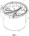
- FIG 1 represents, in perspective, a rinsing device 1 according to a first exemplary embodiment not forming part of the claimed object.
- This rinsing device is also visible in FIG 3 , 4 And 5 .
- It takes the general form of a bucket 8, provided with a handle 2, and comprises a bottom wall 3 and an external circular wall 4 delimiting an interior volume 5.
- a central pillar 10 In this interior volume 5, are mounted a central pillar 10, a tank 40 and a tray 60.
- the bottom wall 3 has at its center an annular protrusion forming an annular promontory 3a surrounding a central cavity 3b.
- the tank 40 comprising said lower wall 45, an external circular wall 46 and a removable cover 47, forms for its part a second reservoir 42 intended for the storage of clean water, possibly mixed with a detergent or another cleaning liquid.
- the tank 40 is also equipped with a chimney 48 extending from the second reservoir 42 towards the upper end of the bucket 8, allowing easy filling of the second reservoir 42.
- the tank 40 comprises a central cavity 50, sinking below the level of the lower wall 45 and delimited by a low wall 50a projecting on the lower wall 45.
- the plate 60 mounted on the central pillar 10, comprises at its center a connection pad 61, mounted on the plate 60 via a bearing 62, configured to cooperate with a connection cavity 91 provided under the head 92 of the brush 90 associated with the rinsing device 1 and shown in the FIG 2A and 2B .
- This broom 90 also has a cleaning pad 93, of the microfiber mop type for example, removably fixed on the lower surface of the head 2, using self-gripping strips or buttonholes for example.
- the broom 90 further comprises a handle 94 mounted on the head 92 by means of a joint 95 of the Cardan type and a free wheel 96 allowing the head 92 to rotate only in one direction relative to the handle 94.
- the plate 60 further comprises wringing rollers 63, provided in this example in the number of three, regularly distributed around the central axis A of the rinsing device 1, and extending radially from this axis A.
- Each wringing roller 63 of substantially frustoconical shape, is mounted mobile in rotation on a base 64; the axis of rotation 65 of the rollers 63 is slightly inclined such that the upper segment of each roller 63 is horizontal.
- each base 64 is mounted on the plate 60 so as to benefit from a certain freedom of movement in the axial direction, springs 66 making it possible to return each base 64, and therefore each roller 63, towards its position projecting the most on the plate 60.
- the tray 60 also includes tufts of brush bristles 66 facilitating cleaning of the broom 90.
- the tray 60 includes three rows of brush bristles 66, each provided along a wringer roller 63.
- the tray 60 further comprises water ejection nozzles 67 intended to eject clean water from the second reservoir 42 onto the mop 93 of the broom 90. More specifically, in the present example, the tray 60 comprises three radial conduits 68 regularly distributed around the central axis A, and therefore extending in a star shape radially from this axis A on the surface of the tray 60. Each of the radial conduits 68 is pierced with a plurality of aligned orifices forming the water ejection nozzles 67. In addition, the inner end of the radial conduits 68 communicates fluidically with an axial conduit 69 of the tray 60, extending along the central axis A from the lower face of the tray 60, through which the clean water from the second reservoir 42 arrives.
- the plate 60 also comprises a locking device 70, taking in the present example the form of a three-branched propeller 71.
- This locking device is rotatably mounted between two positions shown in FIG 10A and 10B .
- each branch 71 covers a radial conduit 68 such that the ejection nozzles 67 are all masked by the blocking device 70.
- each branch 71 In the second position, called erasing and shown in FIG 10B , each branch 71 abuts against a cleat 72 provided on the plate 60 and uncovers the radial conduit 68 such that no obstacle is interposed between the nozzles 67 and the brush 90.
- a cam device or simply a groove 73 is also provided on the surface of the plate 60, opposite each branch 71, in order to guide the rotation of the locking device 70 and ensure the stability of the locking and erasing positions, respectively.
- the plate 60 further comprises a connection socket 74 to the central pillar 10, cylindrical, extending axially from the lower face of the plate 60, coaxially with the axial conduit 69 over a length however less than the latter.
- the central pillar 10 houses a pumping device, making it possible to pump clean water from the second tank 42 towards the ejection nozzles 37, and a rotation drive device, operating simultaneously with the pumping device, making it possible to drive the plate 60 in rotation.
- the central pillar 10 firstly comprises a mounting sleeve 11 comprising a threaded cylindrical part 12, received and screwed into the mounting base 9.
- the mounting sleeve 11 also comprises a horizontal annular support part 13 carrying three threaded blocks 13a.
- the tank 40 is then mounted on the mounting sleeve 11, its central cavity 50 extending within the cylindrical portion 12 of the mounting sleeve 11.
- An annular seal 51 the section of which takes the form of an L, is then placed in a circular groove 52 provided in the lower wall 45 of the tank 40.
- a helical return spring 59 is further installed in the central cavity 50, vertically along the central axis A, its lower portion engaging around a protuberance 58 projecting vertically from the bottom of the central cavity 50, in the center of the latter.
- the central pillar 10 then comprises a frame 14, a piston 15, a first cam cylinder 23 and a second cam cylinder 24 assembled with each other.
- the piston 15, of generally cylindrical shape, although having material removals to reduce its mass, comprises a lower cavity 16 open at its lower end and provided with a neck 17 at its upper end.
- This neck 17 delimits an orifice allowing the lower cavity 16 to communicate with an ejection duct 18 formed axially in the piston 15.
- a ball 19 inserted in the ejection duct 18 is pressed against the neck 17 using a spring 20 resting on a shoulder (not shown) of the ejection duct 18: the ball 19 and the spring 20 thus form a valve closing the neck 17 unless a sufficient threshold pressure is exerted against the ball 19 from the lower cavity 16 of the piston.
- the piston 15 further comprises an upper cavity 21 open at its upper end and communicating with the ejection duct 18 at its lower end.
- the piston 15 also includes pins 22, here three in number, provided at regular intervals on the outer surface of the piston 15.
- Cam cylinders 23, 24, better visible on the FIG 7 And 8 are generally cylindrical parts whose inner surface is provided with reliefs forming cam surfaces 25, 26.
- the cam cylinders 23, 24 are configured to fit together so as to enclose the pins 22 of the piston 15 between the upper cam surface 25, carried by the first cam cylinder 23, and the lower cam surface 26, carried by the second cam cylinder 24.
- the assembly is inserted into the cylindrical internal cavity of the armature 14 and the whole is positioned within the tank 40 such that the contour 14a of the armature 14 rests on the annular seal 51, that the second cam cylinder 24 rests on the wall 50a surrounding the central cavity 50 of the tank 40, that the lower end of the piston 15, provided with a skirt 15a, penetrates into the central cavity 50, and that the upper end of the return spring 59 is received in the lower cavity 16 of the piston 15 and rests against a shoulder 16b of the lower cavity 16.
- the armature 14 is then screwed onto the tapped blocks 13a of the mounting sleeve 13, through coincident bores of the tank 40, which makes it possible to secure the assembly formed by the mounting sleeve 13, the tank 40, the armature 14, the cam cylinders 23, 24 and the piston 15.
- the central pillar 10 further comprises a casing 27 covering the frame 14, the contour 28 of which also applies to the annular seal 51, and provided with an upper opening 29 through which the top of the frame 14 and the piston 15 protrude.
- the casing 27 is then screwed onto the frame 14, which makes it possible to completely secure all of the parts of the central pillar 10. From then on, the entire central pillar 10 can easily be removed from the interior volume 5 of the bucket 8 by unscrewing the mounting sleeve 12 from the mounting base 9 secured to the bottom wall 3 of the bucket 8.
- connection sleeve 74 of the plate 60 is received in the upper cavity 21 of the piston 15 until the lower end of the connection sleeve 74 bears against the lower wall of the upper cavity 21 of the piston 15.
- the axial duct 69 of the plate enters the ejection duct 18 of the piston, an O-ring 75 being provided between an external shoulder of the axial duct 69 and the lower wall of the upper cavity 21 of the piston 15.
- connection sleeve 74 of the plate 60 is provided with axial grooves cooperating with axial grooves 79 of the upper cavity 21 of the piston 15.
- the plate 60 is provided with a pawl 76 comprising a finger configured to penetrate into a locking hole in the piston: the pawl 76 is pushed radially in the direction of the central axis A, and therefore in the direction of the locking hole, using a spring; the pawl 76 also has a handle projecting from the upper surface of the plate 60 allowing a user to push the finger of the pawl 76 out of the locking slot in order to disassemble the plate 60.
- the plate 60 has guide tabs 77, here three in number and mounted under the bases 64, capable of sliding along the casing 27 of the central pillar 10 when the plate 60 rises and falls in the bucket 8 in order to stabilize the plate 60 relative to the central pillar 10 and reinforce its mechanical strength.
- the blocking device 70 In order to operate the rinsing device 1, whether at the start of cleaning to initially moisten the mop 93 of the broom 90 or during cleaning to rinse the mop 93, evacuate the dirt trapped by the latter and re-moisten it before a new cleaning cycle, the blocking device 70 is positioned in its exhaust position then the head 92 of the broom 90 is applied against the plate 60 until the connection pad 61 engages in the connection cavity 91 of the broom 90.
- the mop 93 of the broom is in contact with the wringer rollers 63 and the rows of brush bristles 66.
- the user then exerts a downward force on the broom 90 so as to exert pressure against the plate 60 and therefore to drive the piston 15 downwards against the return force of the return spring 59.
- each pin 22 of the piston 15 will follow the cam surfaces 25, 26 and therefore cause a rotation of the piston 15.
- the first cam surface 25 comprises, in the clockwise direction, a succession of grooves 25a and peaks 25b connected by successively descending ramps 25c then ascending ramps 25d.
- the second cam surface 26 comprises, in the clockwise direction, a succession of descending ramps 26a, in sawtooth form, separated by ditches 26b.
- each descending ramp 26a extends from an angular position located clockwise from the groove 25a to an angular position located beyond the next peak 25b.
- the first and second cam surfaces 25, 26 are thus periodic and have the same number of repetitions, which is moreover a multiple of the number of pins 22 carried by the piston 15.
- the pattern of the cam surfaces 25, 26 is repeated three times, such that 120° separates two grooves 25a and therefore two stable equilibrium positions of the piston 15.
- the pin 22 continues its descent by sliding along the ramp 26a until it falls into the ditch 26b located at the angular coordinate a2, thus following a second movement M2 during which the piston 15 performs a first rotation movement of a2-a1 degrees in the clockwise direction.
- the user can then release the pressure exerted on the plate: the return spring 59 then pushes the piston 15 upwards.
- each pin 22 follows a third upward vertical movement M3 until it meets the upward ramp 25d of the first cam surface 25.
- the pin 22 continues its ascent by sliding along the ramp 25d until it lodges in the next groove 25a, located at an angular coordinate a3, thus following a fourth movement M4 during which the piston performs a second rotation movement of a3-a2 degrees in the clockwise direction.
- the piston 15, and therefore the plate 60 has completed a rotation of a3-a1 degrees in the clockwise direction.
- the ditches 26b are located halfway between the grooves 25a such that the piston 15 travels 60° during descent and 60° during ascent.
- the plate 60 is therefore driven in rotation. Therefore, due to the differences in friction at the interface between the plate 60 and the mop head 92, at the bearing 62 and at the freewheel 96, a relative rotational movement occurs between the plate 60 and the mop head 92: the wringing rollers 63 and the rows of brush bristles 66 thus move along the mop 93, which allows it to be wrung out and cleaned.
- the wringing rollers 63 and the rows of brush bristles 66 have traveled over the entire surface of the mop 93, thus completing the wringing and cleaning of the latter.
- a filling passage P connects the second reservoir 42 and the central cavity 50, forming a compression chamber, of the tank 40.
- the passage section of this filling passage P is limited at two locations. Firstly, upstream, the seal 51 makes it possible to limit the flow of clean water entering the filling passage P at the interface between the frame 14 and the casing 27 on the one hand and the lower wall 45 of the tank 40 on the other hand. Then, downstream, the passage section of the filling passage P is limited by the narrowness of the clearance J left between the wall 50a of the compression chamber 50 and the skirt 15a of the piston 15. In this example, when the piston 15 is in its high rest position, the clearance J measures approximately 0.1 mm.
- this flow rate is sufficient for the compression chamber 50 to be able to fill completely during the interval between two uses of the rinsing device 1, that is to say while the user is using the broom 90 to clean the target surface.
- the compression chamber 50 is capable of filling completely in less than 30 seconds; for this, the filling flow rate via the filling passage P is approximately 1 cl/s.
- this flow rate is sufficiently low relative to the actuation time of the rinsing device 1 to neglect, or at least minimize, the reflux flow rate from the compression chamber 50 to the second reservoir 42 during actuation of the rinsing device 1, i.e. during the descent of the piston 15 into the compression chamber 50.
- the reflux flow rate may be less than the filling flow rate.
- the wall 50a has a beveled profile which causes the clearance J to decrease during the descent of the piston 15 into the compression chamber 50.
- the reflux flow rate via the filling passage P is less than 0.5 cl/s.
- the quantity of water capable of flowing back through the filling passage P during a compression cycle is limited to 1 or 2 mL, which is sufficiently small to allow the pressure to build up in the compression chamber 50 and the water to be ejected through the ejection conduit 18.
- the compression chamber 50 is initially filled with clean water.
- the rapid descent of the piston 15 increases the water pressure in the compression chamber 50 while the neck 17 of the piston 15 is blocked by the ball 19 and the backflow of water via the obstructed filling passage P is negligible given the compression speed.
- the ball 19 is pushed back against its spring 20 and clean water is expelled via the ejection duct 18, the axial duct 69, the radial ducts 68 and the nozzles 67 to the mop 93 of the broom 90.
- the water level in the compression chamber 50 becomes insufficient to perform a new ejection of water, which is a signal to the user that the rinsing is complete and that he can use the brush 90 again to clean the target surface. During this time, the compression chamber 50 can fill again.
- each compression cycle will make it possible to rotate the plate 60, and therefore to clean and wring out the mop 93 of the broom 90, without however re-wetting the latter, the water ejected by the nozzles 67 being intercepted by the branches 71 of the locking device 70 and thus directly diverted to the first tank 41 dedicated to dirty water.
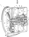
- FIG 11 represents, in perspective, a rinsing device 101 according to an exemplary embodiment of the invention.
- This rinsing device 101 is also visible in FIG 12 , 13 And 14 . It takes the general form of a bucket 108, provided with a handle 102, and comprises a bottom wall 103 and an external circular wall 104 delimiting an interior volume 105. A tank 140 is mounted in this interior volume 105.
- This rinsing device 101 is designed to cooperate with a brush 90 of the same type as that of the first example shown in the drawings. FIG 2A and 2B except that the broom 90 is provided with a device for driving the broom head 92 in rotation.
- the bottom wall 103 has in its center a cylindrical outgrowth forming a promontory 103a provided in its center with a protuberance 103b.
- the tank 140 is suspended by three arms 151 from a suspension ring 152 mounted astride the upper edge of the outer circular wall 104 of the bucket 108. In this suspended state, the tank 140 also rests on the top of the promontory 103a, the protuberance 103b engaging in a cavity 153 provided in the center of the lower wall 145 of the tank 140.
- the tank 140 comprising said lower wall 145, an external circular wall 146 and a removable cover 147, forms for its part a second reservoir 142 intended for the storage of clean water, possibly mixed with a detergent or another cleaning liquid.
- a pumping device 110 for pumping clean water from the second tank 142 towards the plate 160 formed by the cover 147 of the second tank 142, as well as a lifting device 120, for adjusting the position of the brush 90 relative to the plate 160, are mounted within the tank 140 along the central axis A of the rinsing device 101.
- the tank 140 comprises at its center a column 149 extending along the central axis A over approximately half the height of the tank 140, the cavity 153 mentioned above moreover corresponding to the interior space of this column 149.
- a split centering sleeve 111 is threaded loosely around the column 149 and rests on a shoulder of the lower wall 145 of the tank 140.
- a pumping cylinder 112 is placed in the center of the tank 140, around the column 149. It comprises an outer wall 113, substantially cylindrical, extending substantially over the entire height of the tank 140, and an inner wall 114, substantially cylindrical, extending along the column 149 only.
- An Archimedes screw 115 double in the present example, is formed between the outer wall 113 and the inner wall 114 of the pumping cylinder 112.
- the pumping cylinder 112 also comprises an annular skirt 116 extending substantially radially from the upper end of the outer wall 113.
- the top of the column 149 is provided with a cup on which a ball 117 is placed.
- a top hat-shaped hat piece 118 is then attached over the ball 117 and the top of the column 149, the top of the ball 117 being received in a cup provided in the interior space of the top hat piece 118: the top hat piece 118 is thus mounted in rotation relative to the column 149.
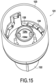
- a transmission part 121 is then placed within the tank 140. This part is also visible on the FIG 15 , 16 , 17 And 18 . It comprises a lower cylinder 122 connected to an upper cylinder 123, of larger diameter and forming a first cam cylinder, and further comprises a central column 124 of smaller diameter than the lower cylinder 122.
- the lower cylinder 122 is received with clearance between the centering sleeve 111 and the inner wall 114 of the cylinder of pumping 112 while the internal cavity 124a formed by the central column 124 is engaged around the cap piece 118 until an axial stop 124b of the internal cavity 124a rests on the top of the cap piece 118.
- the lower cylinder 122 has snap-in fingers 122a designed to irreversibly engage in notches 114a in the inner wall 114 of the pumping cylinder 112 so as to secure the pumping cylinder 112 to the transmission part 121.
- the lower cylinder 122 also has internal ribs 122b allowing the transmission part 121 to be axially blocked by screwing onto a screw thread 149a of the column 149 of the tank 140.
- the central column 124 of the transmission part 121 further comprises at its upper end an upper cavity 124c, open upwards, within which two diametrically opposed radial lugs 124d protrude.
- a spring 125 is then placed around the central column 124 of the transmission part 121, the lower end of the spring 125 resting on a shoulder of the central column 124.
- a 128 follower cylinder is then positioned within the transmission part 121.
- the follower cylinder comprises an outer cylinder 129 extending over the entire height of the upper cylinder of the transmission part 121 and an inner cylinder 130, of diameter substantially equal to that of the column 124 of the transmission part 121, extending over approximately one third of the length of the outer cylinder 129, the outer cylinder 129 and the inner cylinder 130 being connected by a radial ring 131.
- the inner cylinder 130 engages inside the spring 125 while the lower surface of the radial ring 131 is connected to the first bearing 127.
- the follower cylinder 128 also comprises, at the lower end of its outer cylinder 129, two diametrically opposed pins 137 extending radially outwards. As can be better seen in the FIG 18 , the rear edges, upper and lower, of each pin 137 are chamfered.
- a second cam cylinder 132 substantially cylindrical, also visible on the FIG 16 , 17 And 18 , is engaged between the first cam cylinder 123, formed by the outer cylinder of the transmission part 121, and the follower cylinder 128, the second cam cylinder 132 being fixed to the first cam cylinder 123.
- the cam cylinders 123, 132 are portions of generally cylindrical parts whose inner surface is provided with reliefs forming cam surfaces 135, 136.
- the cam cylinders 123, 132 are configured to fit together so as to enclose the pins 137 of the follower cylinder 128 between the lower cam surface 135, carried by the first cam cylinder 123, and the upper cam surface 136, carried by the second cam cylinder 132.
- connection pad 161 is mounted on the follower cylinder 132 by means of a second bearing 162.
- this connection pad 161 is configured to cooperate with a connection cavity 91 provided under the head 92 of the brush 90 associated with the rinsing device 101.
- the lower end of the connection pad 161 extends towards the upper cavity 124c of the column 124 of the transmission part 161 and comprises a dog-engaging finger 163 provided with two diametrically opposed radial lugs 163a.
- the head 92 of the broom 90 is applied against the connection pad 161 so as to engage the latter in the connection cavity 91 of the broom 90.
- the mop 93 of the broom is in contact with the plate 160 formed by the cover 147 of the tank 140.
- the user then actuates the device for driving the broom 90 in rotation by performing vertical back-and-forth movements with the broom 90 or with a movable member of the broom, such as a sleeve, depending on the model of the rotation drive device.
- the head 92 of the broom 90 then begins to rotate, driving with it the rotation of the connection pad 161.
- the dog finger 163 of the connection pad 161 enters the upper cavity 124c of the column 124 of the transmission part 121 such that the lugs 163a of the dog finger 163 push the lugs 124d of the column 124, thus driving the transmission part 121 in rotation.
- the Archimedes screw 115 of the pumping cylinder 112 is rotated, which causes clean water to rise in the pumping cylinder 112 from the clean water tank 142, the clean water then being released along the skirt 116 before flowing along the plate 160 formed by the cover 147 of the tank 140.
- the mop 93 of the broom 90 rotating in contact with the plate 160 can then be rinsed with this clean water and be re-humidified.
- the surface of the plate 160 is slightly inclined outwards so as to allow the evacuation excess clean water to the dirty water tank 141.
- the brush 90 exerts a downward force against the connection pad 161, and therefore against the follower cylinder 128, against the return force of the spring 125.
- each pin 137 of the follower cylinder 128 will follow the cam surfaces 135, 136.
- the first cam surface 135 comprises, in the clockwise direction, a succession of grooves 135a and sawtooth peaks 135b connected by descending ramps 135c.
- the second cam surface 136 comprises, in the clockwise direction, a succession of grooves 136a and sawtooth peaks 136b connected by ascending ramps 136c.
- a groove 135a of the first cam surface 135 is located opposite an ascending ramp 136c of the second cam surface 136 and a groove 136a of the second cam surface 136 is located opposite a descending ramp 135c of the first cam surface 135.
- the first and second cam surfaces 135, 136 are periodic and have the same number of repetitions, which is also a multiple of the number of pins 137 carried by the follower cylinder 128. In the present example, the pattern of the cam surfaces 135, 136 repeats twice.
- a pin 137 has been shown in each of the available stable positions: it should however be understood that these stable positions are in reality occupied successively by the pins 137.
- a unitary pattern thus comprises six lower stable positions 138a located at a lower level, an upper stable position 138b located at a higher level, and two intermediate stable positions 138c and 138d located at two different levels, increasing between the lower level and the upper level.
- a vertical distance of approximately 4 cm separates the lower level from the upper level.
- the force to be exerted against the spring 125 to move from one stable position 138a-138d to the next is then a function of the vertical distance separating this stable position of the groove 135a from the first cam surface 135 located immediately after in the clockwise direction.
- a vertical movement of 1 cm maximum is sufficient to reach the next groove 135a: therefore, a moderate force exerted downwards is sufficient to allow the passage to the next stable position.
- the back-and-forth movement necessary to activate the device for driving the brush 90 in rotation is then sufficient to progress from stable position to stable position until reaching the upper stable position 138b.
- the broom 90 remains in the lower position, in contact with the plate 160, for five back-and-forth movements, which is considered sufficient to rinse the mop 63, then the broom 90 gradually rises over three back-and-forth movements before reaching its upper position.
- the mop 93 of the broom 90 is no longer in contact with the plate 160 and therefore with the water present on the surface of the latter.
- the broom 90 can then be wrung out by centrifugation while continuing to actuate the rotation drive device.
- the dirty water discharged by the mop 93 flows around the plate 160, falls to the bottom of the bucket 108 and is thus collected in the first tank 141 intended for dirty water.
- connection pad 161 when the connection pad 161 is located in the upper position, its clutch finger 163 disengages from the upper cavity 124c of the column 124 of the transmission part 121. From then on, the transmission part 121 and the Archimedes screw 115 are no longer driven, which stops the pumping device 110 and therefore the rise of the clean water.
Landscapes
- Cleaning By Liquid Or Steam (AREA)
- Cleaning Or Drying Semiconductors (AREA)
Claims (5)
- Spülvorrichtung für Reinigungsvorrichtung, die einen ersten Behälter (141), der zum Sammeln von Schmutzwasser vorgesehen ist, das von der Reinigungsvorrichtung (90) stammt,einen zweiten Behälter (142), der zum Speichern von sauberem Wasser vorgesehen ist, undeine mechanische Pumpvorrichtung (110) vom drehbaren Typ umfasst, die dazu ausgestaltet ist, das saubere Wasser, das von dem zweiten Behälter (142) stammt, zu pumpen, um die Reinigungsvorrichtung (90) zu wässern,dadurch gekennzeichnet, dass die Pumpvorrichtung (110) eine archimedische Schraube (115) umfasst, unddass die Pumpvorrichtung (110) ausgestaltet ist, sauberes Wasser zu pumpen, wenn ein Aktivierungsorgan (124) der Pumpvorrichtung (110) durch die Reinigungsvorrichtung (90) drehbar angetrieben wird.
- Spülvorrichtung nach Anspruch 1, die eine Platte (160) umfasst, die dazu vorgesehen ist, die Reinigungsvorrichtung (90) aufzunehmen, und
wobei die Pumpvorrichtung (110) dazu ausgestaltet ist, das saubere Wasser entlang der Platte (160) fließen zu lassen. - Spülvorrichtung nach Anspruch 1 oder 2, wobei die Platte (160) eine Vielzahl von Düsen umfasst, die mit der Pumpvorrichtung verbunden sind.
- Anordnung, die eine Reinigungsvorrichtung (90) und eine Spülvorrichtung (101) nach einem der vorhergehenden Ansprüche umfasst.
- Anordnung nach Anspruch 4, wobei die Reinigungsvorrichtung (90) eine integrierte Schleudervorrichtung, vorzugsweise vom Typ mit Zentrifugierung, umfasst.
Applications Claiming Priority (2)
| Application Number | Priority Date | Filing Date | Title |
|---|---|---|---|
| FR1656652A FR3053880A1 (fr) | 2016-07-12 | 2016-07-12 | Dispositif de rincage |
| FR1657394A FR3053881B1 (fr) | 2016-07-12 | 2016-07-29 | Dispositif de rincage |
Publications (4)
| Publication Number | Publication Date |
|---|---|
| EP3269286A2 EP3269286A2 (de) | 2018-01-17 |
| EP3269286A3 EP3269286A3 (de) | 2018-07-25 |
| EP3269286B1 EP3269286B1 (de) | 2021-09-01 |
| EP3269286B2 true EP3269286B2 (de) | 2025-02-12 |
Family
ID=59285110
Family Applications (1)
| Application Number | Title | Priority Date | Filing Date |
|---|---|---|---|
| EP17181055.9A Active EP3269286B2 (de) | 2016-07-12 | 2017-07-12 | Spülvorrichtung |
Country Status (3)
| Country | Link |
|---|---|
| EP (1) | EP3269286B2 (de) |
| ES (1) | ES2899919T5 (de) |
| FR (1) | FR3053881B1 (de) |
Families Citing this family (11)
| Publication number | Priority date | Publication date | Assignee | Title |
|---|---|---|---|---|
| JP3211808U (ja) * | 2016-08-08 | 2017-08-03 | チェヌ シングアン | 清掃道具 |
| CN111714050A (zh) * | 2019-03-20 | 2020-09-29 | 宁波德润堂智能科技有限公司 | 原位清洗和甩干的平板拖把清洁工具 |
| CN110025273B (zh) * | 2019-05-30 | 2024-05-14 | 北京笑融机器人科技有限公司 | 拖把清洗机及拖把清洗套装 |
| CN112107263A (zh) * | 2019-06-19 | 2020-12-22 | 嘉兴杰创智能电器有限公司 | 擦地机中擦拭物的清洗控制方法 |
| EP4042921B1 (de) * | 2019-10-22 | 2025-01-08 | Fort Plastic & Metalwork (jiaxing) Co., Ltd | Wischobjektreinigungsvorrichtung einer bodenwischmaschine |
| CN111449592B (zh) * | 2020-04-23 | 2021-12-21 | 株洲好媳妇家居用品有限公司 | 一种实现旋转拖把正反转自动切换的拖把桶 |
| CN112401790A (zh) * | 2020-12-04 | 2021-02-26 | 深圳市好运达电器有限公司 | 一种旋转蒸汽拖把和清洗桶系统 |
| USD1039234S1 (en) | 2021-01-07 | 2024-08-13 | Carl Freudenberg Kg | Rinse clean bucket |
| US11832775B2 (en) | 2021-01-07 | 2023-12-05 | Carl Freudenberg Kg | Rinse bucket for floor mop |
| CN215838885U (zh) * | 2021-08-04 | 2022-02-18 | 嘉兴捷顺旅游制品有限公司 | 一种清洁桶及其清洁套装 |
| CN115211783A (zh) * | 2022-07-06 | 2022-10-21 | 胡国云 | 一种离合式旋转拖把清洁工具 |
Citations (12)
| Publication number | Priority date | Publication date | Assignee | Title |
|---|---|---|---|---|
| GB190800742A (en) † | 1908-01-13 | 1908-07-02 | Samuel George Board | Improvements in Mops. |
| GB1520839A (en) † | 1977-06-16 | 1978-08-09 | Sanchez Vazquez J | Mop pail or bucket |
| US4888847A (en) † | 1988-04-20 | 1989-12-26 | Montijo Alicia K | Scrubbing pail device |
| DE29700710U1 (de) † | 1996-03-27 | 1997-06-26 | Diehl, Jens, 61200 Wölfersheim | Vorrichtung zum Reinigen einer einen Schwamm aufweisenden Schwammscheibe |
| EP0781524A2 (de) † | 1995-12-29 | 1997-07-02 | Vermop Salmon Gmbh | Dosiervorrichtung für Desinfektions- und/oder Reinigungsflüssigkeit |
| WO2002000089A1 (en) † | 2000-06-23 | 2002-01-03 | Worre, Regitze | Cleaning bucket |
| WO2004105570A1 (es) † | 2003-05-30 | 2004-12-09 | Carlos Roca Marques | Cubo de fregar |
| DE102004044026A1 (de) † | 2004-09-09 | 2006-03-16 | BSH Bosch und Siemens Hausgeräte GmbH | Vorrichtung zum Entfeuchten oder Befeuchten eines Feuchtwischers |
| US20070113418A1 (en) † | 2005-08-16 | 2007-05-24 | Robert Palmer | Mopping system method of use |
| TWM414930U (en) † | 2011-06-13 | 2011-11-01 | Nat Univ Chin Yi Technology | Mop cleaning device |
| WO2011150617A1 (zh) † | 2010-05-31 | 2011-12-08 | Zhao Yimei | 拖把清洗装置 |
| US9226640B1 (en) † | 2015-08-14 | 2016-01-05 | Kai Wulff | Mop trolley with a central mop sprayer and mop rest |
-
2016
- 2016-07-29 FR FR1657394A patent/FR3053881B1/fr active Active
-
2017
- 2017-07-12 ES ES17181055T patent/ES2899919T5/es active Active
- 2017-07-12 EP EP17181055.9A patent/EP3269286B2/de active Active
Patent Citations (12)
| Publication number | Priority date | Publication date | Assignee | Title |
|---|---|---|---|---|
| GB190800742A (en) † | 1908-01-13 | 1908-07-02 | Samuel George Board | Improvements in Mops. |
| GB1520839A (en) † | 1977-06-16 | 1978-08-09 | Sanchez Vazquez J | Mop pail or bucket |
| US4888847A (en) † | 1988-04-20 | 1989-12-26 | Montijo Alicia K | Scrubbing pail device |
| EP0781524A2 (de) † | 1995-12-29 | 1997-07-02 | Vermop Salmon Gmbh | Dosiervorrichtung für Desinfektions- und/oder Reinigungsflüssigkeit |
| DE29700710U1 (de) † | 1996-03-27 | 1997-06-26 | Diehl, Jens, 61200 Wölfersheim | Vorrichtung zum Reinigen einer einen Schwamm aufweisenden Schwammscheibe |
| WO2002000089A1 (en) † | 2000-06-23 | 2002-01-03 | Worre, Regitze | Cleaning bucket |
| WO2004105570A1 (es) † | 2003-05-30 | 2004-12-09 | Carlos Roca Marques | Cubo de fregar |
| DE102004044026A1 (de) † | 2004-09-09 | 2006-03-16 | BSH Bosch und Siemens Hausgeräte GmbH | Vorrichtung zum Entfeuchten oder Befeuchten eines Feuchtwischers |
| US20070113418A1 (en) † | 2005-08-16 | 2007-05-24 | Robert Palmer | Mopping system method of use |
| WO2011150617A1 (zh) † | 2010-05-31 | 2011-12-08 | Zhao Yimei | 拖把清洗装置 |
| TWM414930U (en) † | 2011-06-13 | 2011-11-01 | Nat Univ Chin Yi Technology | Mop cleaning device |
| US9226640B1 (en) † | 2015-08-14 | 2016-01-05 | Kai Wulff | Mop trolley with a central mop sprayer and mop rest |
Non-Patent Citations (5)
| Title |
|---|
| internet WIKIPEDIA, "Archimedes' screw : Revision history", [cite 29.02.2024] † |
| internet WIKIPEDIA, "Archimedes' screw", [cite 29.02.2024] † |
| Statement from Ms. Leyi Li † |
| Wikipedia : Archimedes’ screw † |
| Wikipedia excerpt "Archimedische Schraube" † |
Also Published As
| Publication number | Publication date |
|---|---|
| EP3269286A3 (de) | 2018-07-25 |
| ES2899919T3 (es) | 2022-03-15 |
| EP3269286B1 (de) | 2021-09-01 |
| FR3053881A1 (fr) | 2018-01-19 |
| FR3053881B1 (fr) | 2019-01-25 |
| EP3269286A2 (de) | 2018-01-17 |
| ES2899919T5 (en) | 2025-05-12 |
Similar Documents
| Publication | Publication Date | Title |
|---|---|---|
| EP3269286B2 (de) | Spülvorrichtung | |
| FR2966037A3 (fr) | Ensemble balai-eponge | |
| US10750923B2 (en) | Rinsing device | |
| EP1510158A1 (de) | Vorrichtung und Methode zur Herstellung eines Getränkes aus einer in einer Portionspackung enthaltenen Substanz | |
| WO2004071682A1 (fr) | Dispositif de nettoyage d’un tube a paroi lisse | |
| FR2502483A1 (fr) | Appareil et procede pour distribuer du savon liquide | |
| WO2013178927A1 (fr) | Distributeur de produit visqueux | |
| EP0017519A2 (de) | Trockenstaubsauger für Bodenflächen | |
| FR3002429A1 (fr) | Balai a tete basculante automatique pour nettoyage de surface | |
| EP2934832A1 (de) | Lebensmittelzerkleinerungsvorrichtung mit einer oszillierenden bewegung und einem waschbaren wechselbehälter | |
| WO2013014380A1 (fr) | Systeme de conditionnement et d'application de produit, notamment de produit cosmetique | |
| FR2931352A1 (fr) | Appareil electromenager domestique pour laver un biberon. | |
| FR3053880A1 (fr) | Dispositif de rincage | |
| FR3098129A1 (fr) | Distributeur de produit fluide | |
| EP2126229A1 (de) | Vorrichtung mit einem geschützten reinigungssystem für toilettenschüsseln | |
| CA2317930C (fr) | Pompe destinee a equiper un recipient | |
| EP2732742B1 (de) | Drehkopf zum Reinigen von einem Behälter | |
| EP0663172B1 (de) | Vorrichtung für eine Getränkezubereitung, bei der eine Flüssigkeit durch ein Substrat strömt | |
| EP1191874A1 (de) | Einstückige reinigungsvorrichtung mit einer eine haftschicht aufweisenden rolle und verfahren zu ihrer herstellung | |
| FR2772583A1 (fr) | Distributeur de produit de nettoyage, de type savon liquide ou semi-liquide | |
| FR3078061A1 (fr) | Distributeur de produit fluide. | |
| FR3039115A1 (fr) | Brosse jante | |
| EP1714596B1 (de) | Vorrichtung zur Ausgabe von pulverförmigem Material | |
| FR2854041A1 (fr) | Dispositif de nettoyage pour balayettes de toilette, notamment en milieu public | |
| WO2026022175A1 (fr) | Dispositif de distribution nasale |
Legal Events
| Date | Code | Title | Description |
|---|---|---|---|
| PUAI | Public reference made under article 153(3) epc to a published international application that has entered the european phase |
Free format text: ORIGINAL CODE: 0009012 |
|
| STAA | Information on the status of an ep patent application or granted ep patent |
Free format text: STATUS: THE APPLICATION HAS BEEN PUBLISHED |
|
| AK | Designated contracting states |
Kind code of ref document: A2 Designated state(s): AL AT BE BG CH CY CZ DE DK EE ES FI FR GB GR HR HU IE IS IT LI LT LU LV MC MK MT NL NO PL PT RO RS SE SI SK SM TR |
|
| AX | Request for extension of the european patent |
Extension state: BA ME |
|
| RIC1 | Information provided on ipc code assigned before grant |
Ipc: A47L 13/256 20060101ALI20180319BHEP Ipc: A47L 13/60 20060101AFI20180319BHEP Ipc: A47L 13/50 20060101ALI20180319BHEP |
|
| PUAL | Search report despatched |
Free format text: ORIGINAL CODE: 0009013 |
|
| AK | Designated contracting states |
Kind code of ref document: A3 Designated state(s): AL AT BE BG CH CY CZ DE DK EE ES FI FR GB GR HR HU IE IS IT LI LT LU LV MC MK MT NL NO PL PT RO RS SE SI SK SM TR |
|
| AX | Request for extension of the european patent |
Extension state: BA ME |
|
| RIC1 | Information provided on ipc code assigned before grant |
Ipc: A47L 13/256 20060101ALI20180620BHEP Ipc: A47L 13/60 20060101AFI20180620BHEP Ipc: A47L 13/50 20060101ALI20180620BHEP |
|
| STAA | Information on the status of an ep patent application or granted ep patent |
Free format text: STATUS: REQUEST FOR EXAMINATION WAS MADE |
|
| 17P | Request for examination filed |
Effective date: 20190124 |
|
| RBV | Designated contracting states (corrected) |
Designated state(s): AL AT BE BG CH CY CZ DE DK EE ES FI FR GB GR HR HU IE IS IT LI LT LU LV MC MK MT NL NO PL PT RO RS SE SI SK SM TR |
|
| STAA | Information on the status of an ep patent application or granted ep patent |
Free format text: STATUS: EXAMINATION IS IN PROGRESS |
|
| 17Q | First examination report despatched |
Effective date: 20190703 |
|
| GRAP | Despatch of communication of intention to grant a patent |
Free format text: ORIGINAL CODE: EPIDOSNIGR1 |
|
| STAA | Information on the status of an ep patent application or granted ep patent |
Free format text: STATUS: GRANT OF PATENT IS INTENDED |
|
| INTG | Intention to grant announced |
Effective date: 20210414 |
|
| GRAS | Grant fee paid |
Free format text: ORIGINAL CODE: EPIDOSNIGR3 |
|
| GRAA | (expected) grant |
Free format text: ORIGINAL CODE: 0009210 |
|
| STAA | Information on the status of an ep patent application or granted ep patent |
Free format text: STATUS: THE PATENT HAS BEEN GRANTED |
|
| AK | Designated contracting states |
Kind code of ref document: B1 Designated state(s): AL AT BE BG CH CY CZ DE DK EE ES FI FR GB GR HR HU IE IS IT LI LT LU LV MC MK MT NL NO PL PT RO RS SE SI SK SM TR |
|
| REG | Reference to a national code |
Ref country code: GB Ref legal event code: FG4D Free format text: NOT ENGLISH |
|
| REG | Reference to a national code |
Ref country code: CH Ref legal event code: EP Ref country code: AT Ref legal event code: REF Ref document number: 1425313 Country of ref document: AT Kind code of ref document: T Effective date: 20210915 |
|
| REG | Reference to a national code |
Ref country code: DE Ref legal event code: R096 Ref document number: 602017045040 Country of ref document: DE |
|
| REG | Reference to a national code |
Ref country code: IE Ref legal event code: FG4D Free format text: LANGUAGE OF EP DOCUMENT: FRENCH |
|
| REG | Reference to a national code |
Ref country code: LT Ref legal event code: MG9D |
|
| REG | Reference to a national code |
Ref country code: NL Ref legal event code: MP Effective date: 20210901 |
|
| PG25 | Lapsed in a contracting state [announced via postgrant information from national office to epo] |
Ref country code: RS Free format text: LAPSE BECAUSE OF FAILURE TO SUBMIT A TRANSLATION OF THE DESCRIPTION OR TO PAY THE FEE WITHIN THE PRESCRIBED TIME-LIMIT Effective date: 20210901 Ref country code: SE Free format text: LAPSE BECAUSE OF FAILURE TO SUBMIT A TRANSLATION OF THE DESCRIPTION OR TO PAY THE FEE WITHIN THE PRESCRIBED TIME-LIMIT Effective date: 20210901 Ref country code: LT Free format text: LAPSE BECAUSE OF FAILURE TO SUBMIT A TRANSLATION OF THE DESCRIPTION OR TO PAY THE FEE WITHIN THE PRESCRIBED TIME-LIMIT Effective date: 20210901 Ref country code: BG Free format text: LAPSE BECAUSE OF FAILURE TO SUBMIT A TRANSLATION OF THE DESCRIPTION OR TO PAY THE FEE WITHIN THE PRESCRIBED TIME-LIMIT Effective date: 20211201 Ref country code: NO Free format text: LAPSE BECAUSE OF FAILURE TO SUBMIT A TRANSLATION OF THE DESCRIPTION OR TO PAY THE FEE WITHIN THE PRESCRIBED TIME-LIMIT Effective date: 20211201 Ref country code: HR Free format text: LAPSE BECAUSE OF FAILURE TO SUBMIT A TRANSLATION OF THE DESCRIPTION OR TO PAY THE FEE WITHIN THE PRESCRIBED TIME-LIMIT Effective date: 20210901 Ref country code: FI Free format text: LAPSE BECAUSE OF FAILURE TO SUBMIT A TRANSLATION OF THE DESCRIPTION OR TO PAY THE FEE WITHIN THE PRESCRIBED TIME-LIMIT Effective date: 20210901 |
|
| REG | Reference to a national code |
Ref country code: AT Ref legal event code: MK05 Ref document number: 1425313 Country of ref document: AT Kind code of ref document: T Effective date: 20210901 |
|
| PG25 | Lapsed in a contracting state [announced via postgrant information from national office to epo] |
Ref country code: PL Free format text: LAPSE BECAUSE OF FAILURE TO SUBMIT A TRANSLATION OF THE DESCRIPTION OR TO PAY THE FEE WITHIN THE PRESCRIBED TIME-LIMIT Effective date: 20210901 Ref country code: LV Free format text: LAPSE BECAUSE OF FAILURE TO SUBMIT A TRANSLATION OF THE DESCRIPTION OR TO PAY THE FEE WITHIN THE PRESCRIBED TIME-LIMIT Effective date: 20210901 Ref country code: GR Free format text: LAPSE BECAUSE OF FAILURE TO SUBMIT A TRANSLATION OF THE DESCRIPTION OR TO PAY THE FEE WITHIN THE PRESCRIBED TIME-LIMIT Effective date: 20211202 |
|
| REG | Reference to a national code |
Ref country code: ES Ref legal event code: FG2A Ref document number: 2899919 Country of ref document: ES Kind code of ref document: T3 Effective date: 20220315 |
|
| PG25 | Lapsed in a contracting state [announced via postgrant information from national office to epo] |
Ref country code: AT Free format text: LAPSE BECAUSE OF FAILURE TO SUBMIT A TRANSLATION OF THE DESCRIPTION OR TO PAY THE FEE WITHIN THE PRESCRIBED TIME-LIMIT Effective date: 20210901 |
|
| PG25 | Lapsed in a contracting state [announced via postgrant information from national office to epo] |
Ref country code: IS Free format text: LAPSE BECAUSE OF FAILURE TO SUBMIT A TRANSLATION OF THE DESCRIPTION OR TO PAY THE FEE WITHIN THE PRESCRIBED TIME-LIMIT Effective date: 20220101 Ref country code: SM Free format text: LAPSE BECAUSE OF FAILURE TO SUBMIT A TRANSLATION OF THE DESCRIPTION OR TO PAY THE FEE WITHIN THE PRESCRIBED TIME-LIMIT Effective date: 20210901 Ref country code: SK Free format text: LAPSE BECAUSE OF FAILURE TO SUBMIT A TRANSLATION OF THE DESCRIPTION OR TO PAY THE FEE WITHIN THE PRESCRIBED TIME-LIMIT Effective date: 20210901 Ref country code: RO Free format text: LAPSE BECAUSE OF FAILURE TO SUBMIT A TRANSLATION OF THE DESCRIPTION OR TO PAY THE FEE WITHIN THE PRESCRIBED TIME-LIMIT Effective date: 20210901 Ref country code: PT Free format text: LAPSE BECAUSE OF FAILURE TO SUBMIT A TRANSLATION OF THE DESCRIPTION OR TO PAY THE FEE WITHIN THE PRESCRIBED TIME-LIMIT Effective date: 20220103 Ref country code: NL Free format text: LAPSE BECAUSE OF FAILURE TO SUBMIT A TRANSLATION OF THE DESCRIPTION OR TO PAY THE FEE WITHIN THE PRESCRIBED TIME-LIMIT Effective date: 20210901 Ref country code: EE Free format text: LAPSE BECAUSE OF FAILURE TO SUBMIT A TRANSLATION OF THE DESCRIPTION OR TO PAY THE FEE WITHIN THE PRESCRIBED TIME-LIMIT Effective date: 20210901 Ref country code: AL Free format text: LAPSE BECAUSE OF FAILURE TO SUBMIT A TRANSLATION OF THE DESCRIPTION OR TO PAY THE FEE WITHIN THE PRESCRIBED TIME-LIMIT Effective date: 20210901 |
|
| REG | Reference to a national code |
Ref country code: DE Ref legal event code: R026 Ref document number: 602017045040 Country of ref document: DE |
|
| PLBI | Opposition filed |
Free format text: ORIGINAL CODE: 0009260 |
|
| PLAB | Opposition data, opponent's data or that of the opponent's representative modified |
Free format text: ORIGINAL CODE: 0009299OPPO |
|
| PLAX | Notice of opposition and request to file observation + time limit sent |
Free format text: ORIGINAL CODE: EPIDOSNOBS2 |
|
| 26 | Opposition filed |
Opponent name: RGTH Effective date: 20220601 |
|
| R26 | Opposition filed (corrected) |
Opponent name: RGTH Effective date: 20220601 |
|
| PG25 | Lapsed in a contracting state [announced via postgrant information from national office to epo] |
Ref country code: DK Free format text: LAPSE BECAUSE OF FAILURE TO SUBMIT A TRANSLATION OF THE DESCRIPTION OR TO PAY THE FEE WITHIN THE PRESCRIBED TIME-LIMIT Effective date: 20210901 |
|
| PG25 | Lapsed in a contracting state [announced via postgrant information from national office to epo] |
Ref country code: SI Free format text: LAPSE BECAUSE OF FAILURE TO SUBMIT A TRANSLATION OF THE DESCRIPTION OR TO PAY THE FEE WITHIN THE PRESCRIBED TIME-LIMIT Effective date: 20210901 |
|
| PLBB | Reply of patent proprietor to notice(s) of opposition received |
Free format text: ORIGINAL CODE: EPIDOSNOBS3 |
|
| PG25 | Lapsed in a contracting state [announced via postgrant information from national office to epo] |
Ref country code: MC Free format text: LAPSE BECAUSE OF FAILURE TO SUBMIT A TRANSLATION OF THE DESCRIPTION OR TO PAY THE FEE WITHIN THE PRESCRIBED TIME-LIMIT Effective date: 20210901 |
|
| REG | Reference to a national code |
Ref country code: CH Ref legal event code: PL |
|
| REG | Reference to a national code |
Ref country code: DE Ref legal event code: R082 Ref document number: 602017045040 Country of ref document: DE Representative=s name: CBDL PATENTANWAELTE GBR, DE Ref country code: DE Ref legal event code: R082 Ref document number: 602017045040 Country of ref document: DE Representative=s name: CBDL PATENTANWAELTE EGBR, DE |
|
| REG | Reference to a national code |
Ref country code: BE Ref legal event code: MM Effective date: 20220731 |
|
| PG25 | Lapsed in a contracting state [announced via postgrant information from national office to epo] |
Ref country code: LU Free format text: LAPSE BECAUSE OF NON-PAYMENT OF DUE FEES Effective date: 20220712 Ref country code: LI Free format text: LAPSE BECAUSE OF NON-PAYMENT OF DUE FEES Effective date: 20220731 Ref country code: CH Free format text: LAPSE BECAUSE OF NON-PAYMENT OF DUE FEES Effective date: 20220731 |
|
| PG25 | Lapsed in a contracting state [announced via postgrant information from national office to epo] |
Ref country code: BE Free format text: LAPSE BECAUSE OF NON-PAYMENT OF DUE FEES Effective date: 20220731 |
|
| PG25 | Lapsed in a contracting state [announced via postgrant information from national office to epo] |
Ref country code: IE Free format text: LAPSE BECAUSE OF NON-PAYMENT OF DUE FEES Effective date: 20220712 |
|
| PG25 | Lapsed in a contracting state [announced via postgrant information from national office to epo] |
Ref country code: HU Free format text: LAPSE BECAUSE OF FAILURE TO SUBMIT A TRANSLATION OF THE DESCRIPTION OR TO PAY THE FEE WITHIN THE PRESCRIBED TIME-LIMIT; INVALID AB INITIO Effective date: 20170712 |
|
| PG25 | Lapsed in a contracting state [announced via postgrant information from national office to epo] |
Ref country code: MK Free format text: LAPSE BECAUSE OF FAILURE TO SUBMIT A TRANSLATION OF THE DESCRIPTION OR TO PAY THE FEE WITHIN THE PRESCRIBED TIME-LIMIT Effective date: 20210901 Ref country code: CY Free format text: LAPSE BECAUSE OF FAILURE TO SUBMIT A TRANSLATION OF THE DESCRIPTION OR TO PAY THE FEE WITHIN THE PRESCRIBED TIME-LIMIT Effective date: 20210901 |
|
| PG25 | Lapsed in a contracting state [announced via postgrant information from national office to epo] |
Ref country code: MT Free format text: LAPSE BECAUSE OF FAILURE TO SUBMIT A TRANSLATION OF THE DESCRIPTION OR TO PAY THE FEE WITHIN THE PRESCRIBED TIME-LIMIT Effective date: 20210901 |
|
| PUAH | Patent maintained in amended form |
Free format text: ORIGINAL CODE: 0009272 |
|
| STAA | Information on the status of an ep patent application or granted ep patent |
Free format text: STATUS: PATENT MAINTAINED AS AMENDED |
|
| 27A | Patent maintained in amended form |
Effective date: 20250212 |
|
| AK | Designated contracting states |
Kind code of ref document: B2 Designated state(s): AL AT BE BG CH CY CZ DE DK EE ES FI FR GB GR HR HU IE IS IT LI LT LU LV MC MK MT NL NO PL PT RO RS SE SI SK SM TR |
|
| REG | Reference to a national code |
Ref country code: DE Ref legal event code: R102 Ref document number: 602017045040 Country of ref document: DE |
|
| REG | Reference to a national code |
Ref country code: ES Ref legal event code: DC2A Ref document number: 2899919 Country of ref document: ES Kind code of ref document: T5 Effective date: 20250512 |
|
| PGFP | Annual fee paid to national office [announced via postgrant information from national office to epo] |
Ref country code: CZ Payment date: 20250623 Year of fee payment: 9 |
|
| PGFP | Annual fee paid to national office [announced via postgrant information from national office to epo] |
Ref country code: ES Payment date: 20250801 Year of fee payment: 9 |
|
| PGFP | Annual fee paid to national office [announced via postgrant information from national office to epo] |
Ref country code: DE Payment date: 20250729 Year of fee payment: 9 |
|
| PGFP | Annual fee paid to national office [announced via postgrant information from national office to epo] |
Ref country code: IT Payment date: 20250721 Year of fee payment: 9 |
|
| PGFP | Annual fee paid to national office [announced via postgrant information from national office to epo] |
Ref country code: GB Payment date: 20250728 Year of fee payment: 9 |
|
| PGFP | Annual fee paid to national office [announced via postgrant information from national office to epo] |
Ref country code: FR Payment date: 20250725 Year of fee payment: 9 |
|
| PG25 | Lapsed in a contracting state [announced via postgrant information from national office to epo] |
Ref country code: TR Free format text: LAPSE BECAUSE OF FAILURE TO SUBMIT A TRANSLATION OF THE DESCRIPTION OR TO PAY THE FEE WITHIN THE PRESCRIBED TIME-LIMIT Effective date: 20210901 |