EP3268552B1 - Greenhouse - Google Patents
Greenhouse Download PDFInfo
- Publication number
- EP3268552B1 EP3268552B1 EP16723821.1A EP16723821A EP3268552B1 EP 3268552 B1 EP3268552 B1 EP 3268552B1 EP 16723821 A EP16723821 A EP 16723821A EP 3268552 B1 EP3268552 B1 EP 3268552B1
- Authority
- EP
- European Patent Office
- Prior art keywords
- trusses
- stringers
- greenhouse
- greenhouse according
- covering
- Prior art date
- Legal status (The legal status is an assumption and is not a legal conclusion. Google has not performed a legal analysis and makes no representation as to the accuracy of the status listed.)
- Active
Links
Images


Classifications
-
- A—HUMAN NECESSITIES
- A01—AGRICULTURE; FORESTRY; ANIMAL HUSBANDRY; HUNTING; TRAPPING; FISHING
- A01G—HORTICULTURE; CULTIVATION OF VEGETABLES, FLOWERS, RICE, FRUIT, VINES, HOPS OR SEAWEED; FORESTRY; WATERING
- A01G9/00—Cultivation in receptacles, forcing-frames or greenhouses; Edging for beds, lawn or the like
- A01G9/24—Devices or systems for heating, ventilating, regulating temperature, illuminating, or watering, in greenhouses, forcing-frames, or the like
- A01G9/241—Arrangement of opening or closing systems for windows and ventilation panels
-
- A—HUMAN NECESSITIES
- A01—AGRICULTURE; FORESTRY; ANIMAL HUSBANDRY; HUNTING; TRAPPING; FISHING
- A01G—HORTICULTURE; CULTIVATION OF VEGETABLES, FLOWERS, RICE, FRUIT, VINES, HOPS OR SEAWEED; FORESTRY; WATERING
- A01G9/00—Cultivation in receptacles, forcing-frames or greenhouses; Edging for beds, lawn or the like
- A01G9/14—Greenhouses
-
- Y—GENERAL TAGGING OF NEW TECHNOLOGICAL DEVELOPMENTS; GENERAL TAGGING OF CROSS-SECTIONAL TECHNOLOGIES SPANNING OVER SEVERAL SECTIONS OF THE IPC; TECHNICAL SUBJECTS COVERED BY FORMER USPC CROSS-REFERENCE ART COLLECTIONS [XRACs] AND DIGESTS
- Y02—TECHNOLOGIES OR APPLICATIONS FOR MITIGATION OR ADAPTATION AGAINST CLIMATE CHANGE
- Y02A—TECHNOLOGIES FOR ADAPTATION TO CLIMATE CHANGE
- Y02A40/00—Adaptation technologies in agriculture, forestry, livestock or agroalimentary production
- Y02A40/10—Adaptation technologies in agriculture, forestry, livestock or agroalimentary production in agriculture
- Y02A40/25—Greenhouse technology, e.g. cooling systems therefor
Definitions
- the present invention relates to the greenhouse production sector, and more in particular the subject matter of the invention is a greenhouse with a roof, in which the covering is integrated in the structural elements of the roof.
- Greenhouse cultivation has been known for hundreds of years.
- the most commonly used types of greenhouses are formed by buildings whose roofs have coverings made of sheets of glass, sheets made of plastic material or coverings made of a film of plastic material, naturally all capable of allowing sunlight to pass through.
- the roofs can be formed of sloping flat pitches opposite relative to the ridge of the roof, generally made of sheets of glass or plastic material, or also of barrel-vaulted corrugated structures, typically made of films of plastic material.
- a roof can comprise a single ridge with only two opposite sloping pitches (or a single barrel vault) or multiple ridges aligned parallel to each other.
- a greenhouse structure and roof structures are known from document US-A-5655335 .
- some types have pitches with portions thereof tilting between a closed position and an open position.
- the structures of the roofs are provided with supporting trusses and, above the trusses, structures carrying the covering elements that comprise the aforesaid sloping pitches or barrel vaults.
- This construction method can be complex to assemble and can therefore require some time for installation.
- the aim of the present invention is to solve the aforesaid problems in greenhouses of known type.
- an important object of the present invention is to produce a greenhouse with covering structurally integrated in the roof that facilitates the assembly and disassembly of the same greenhouse.
- Another important object of the present invention is to produce a greenhouse that facilitates assembly and removal of the covering cloths.
- Yet another important object of the present invention is to produce a greenhouse with covering structurally integrated in the roof that allows easy airing of the greenhouse.
- One more important object of the present invention is to produce a greenhouse that is modular in construction.
- the roof of the greenhouse is formed by modular elements, namely the trusses, which contain the covering and, above all, the covering components, greatly facilitating assembly thereof.
- the trusses comprise a plurality of diagonal rods to support sloping covering pitches.
- the trusses comprise a plurality of vertical rods for connecting the lower and upper stringers. The diagonal rods are fixed by the respective upper ends to the vertical rods and by the respective lower ends to the lower stringers. This structure allows optimization of the spaces in the trusses for housing the covering.
- gutters can be arranged in the areas of common convergence at the bottom of contiguous pitches; preferably, contiguous pairs of the diagonal rods defining the supports of said contiguous pitches are fastened to respective lower stringers with interposing of a space for housing a respective said gutter. In this way, assembly of the gutters is also greatly facilitated.
- the covering comprises sloping pitches to define, in pairs of adjacent pitches, areas of common convergence at the bottom and upper ridges; advantageously, the sloping pitches follow the diagonal rods of the truss.
- the covering comprises a flexible covering film at least partially transparent to light and/or sheets made of material at least partially transparent to light.
- the greenhouse comprises means for opening/closing at least one portion of the covering of said roof, to allow airing of the greenhouse from above.
- the covering can comprise a flexible covering film at least partially transparent to light combined with opening/closing means that comprise:
- these guides are produced along respective diagonal rods of said truss.
- the opening/closing means of at least one portion of the covering of the roof can comprise openable windows.
- said openable windows are tilting according to an axis parallel to the ridges of the sloping pitches.
- the greenhouse comprises at least one cloth for insulating and/or shading and/or reflecting the sun's rays/heat associated directly with one or more of the lower stringers of said trusses and/or with one or more of the upper stringers of said trusses.
- the greenhouse comprises at least three of said trusses placed side by side correspondingly, there being provided at least a first cloth between a first pair of lower stringers and at least a second cloth between the subsequent pair of lower stringers, and/or at least one cloth between a first pair of upper stringers and at least a further cloth between the second pair of upper stringers.
- a greenhouse according to the invention is indicated as a whole with the number 10.
- the greenhouse 10 is provided with a roof 11, which comprises a plurality of trusses 12 substantially identical to one another, arranged parallel, preferably equidistant, according to the longitudinal direction X, i.e. the depth of the greenhouse, or the direction orthogonal to the plane of the trusses.
- Each truss 12 comprises an upper stringer 13, a lower stringer 14, vertical rods 15 and diagonal rods 16.
- the connection nodes of stringers and rods are substantially rigid, for example produced by means of plates or sleeves fastened by threaded connections, or also by welding.
- each vertical end rod 15A and one vertical central rod 15B there are provided two vertical end rods 15A and one vertical central rod 15B. Moreover, there are also provided other intermediate vertical rods 15.
- the diagonal rods 16 are fastened by the respective upper ends to the vertical rods 15 and by the respective lower ends to the lower stringers 14.
- the trusses 12 are connected in the longitudinal direction of the greenhouse, by longitudinal rods 17, for example fastened to the same trusses in the areas in which the diagonal rods 16 are fastened to the vertical rods 15.
- gutters 18 arranged in the longitudinal direction of the greenhouse, fastened to the lower stringers 14 of the trusses 12, connecting these latter longitudinally to one another.
- the pairs of diagonal rods 16 of one truss that converge toward the common area of fastening to the lower stringer 14, are fastened thereto with interposing of a space for housing a respective gutter 18.
- the covering of the roof 11 is arranged between the lower 14 and upper 13 stringers of the trusses 12, i.e. is produced neither above nor below the trusses.
- the covering is produced by pairs of substantially flat adjacent sloping pitches 20, with opposite slope, which provide, in pairs, areas of common convergence at the bottom and upper ridges.
- the covering is in practice, in this example, a sequence of sloping pitches. It is understood that in other examples the ridges could be produced in the common area of sloping pitches and vertical pitches.
- the upper ridges are, for example, produced by longitudinal caps 19 fastened on the longitudinal rods 17, in practice press formed profiles, on which the pitch coverings are fastened.
- the sloping pitches 20 follow the diagonal rods 16 of the trusses 12 and, more in particular, these diagonal rods support the pitches 20.
- the greenhouse is provided with means 21 for opening/closing part of the covering of the roof, to allow airing of the greenhouse from above.
- the greenhouse comprises a flexible covering film 22, transparent to light, for example made of PVC.
- the opening/closing means 21 comprise a roller 23 for winding of the film 22, oriented with its winding axis orthogonal to the planes of the trusses 12, i.e. parallel to the longitudinal direction X of the greenhouse.
- These means 21 also comprise a first device for sliding the roller 23 comprising sliding guides 25 associated with the diagonal rods 16 and a second device for rotating the roller 23 to wind/unwind the film, not shown in the figures.
- the film 22 associated with a roller 23 is wound on the same roller and the roller is in the upper end of travel position of the sliding guide 25, or the related pitch is "open".
- An upper edge of the film 22 is fastened to a related longitudinal cap 19, while the rest of the film is wound on the roller.
- the roller is made to slide downward along the guides 25 and, simultaneously, the roller 23 is made to rotate to unwind the film (an edge is fastened to the ridge of the roof by the longitudinal cap 19), which thus covers the related pitch, producing the covering.
- the roller is made to rotate and simultaneously slide in the opposite directions to those of closing.
- the axis of the roller can be integral with a toothed wheel meshed with a rack parallel to the guide 25, and the same axis of the roller can be moved by an actuator along the guide 25, so that during sliding thereon, the toothed wheel is obliged to rotate, performing winding/unwinding of the belt.
- the drive mechanisms that allow movement of the roller can be of manual, or motorized, and therefore automated, type to allow remote control and programming of opening/closing according to time and/or environmental parameters.
- the guides 25 are, for example, produced below by the diagonal rods 16 and above by secondary oblique rods 16A parallel thereto, for example fastened at an upper end to the vertical rods 15, and at the lower end on the diagonal rods 16, so that the rollers 23 are constrained to slide inside the slots defined between said two rods 16 and 16A.
- sliding guides 25A (visible in detail in Fig. 4 ), arranged in the areas of the roof between two subsequent trusses, to prevent excessive deformations of the same roller between the trusses, for example formed of two oblique secondary rods 16B superimposed to define the slots in which the roller slides.
- These two oblique secondary rods 16B are, for example, fastened by the ends thereof to the gutters 18 and by the opposite ends to the longitudinal connecting rods 17 of the subsequent trusses.
- the roller 23 has a length more or less equal to the longitudinal depth (direction X) of the greenhouse, i.e. of the roof, so that with the movement of a roller it is possible to open or close the whole length of a pitch of the covering.
- a roller for each pitch there is provided a roller for each pitch. It is understood that it is possible to use rollers with covering films only on some pitches of the roof or also rollers with films that cover only predetermined longitudinal portions of the pitches.
- Fig. 5 shows a variant of the opening/closing means 21 of part of the covering of the roof, which consists of openable windows or hatches 123, for example partially made of polyethylene.
- These openable windows 123 are tilting according to an axis parallel to the ridges of the sloping pitches.
- window cloths are hinged with reference to their upper side and are provided on the part of the pitch closest to the ridges.
- means 125 that comprise rotary slides with telescoping arms, complete with gear motors. It is clear that the windows can occupy the whole of the longitudinal extension of the pitches, or only part of them.
- the covering of the greenhouse can also comprise parts made of rigid sheets 126, such as in Fig. 5 , flat or corrugated or curved, preferably made of material substantially transparent to light, for example glass.
- gutters 18 At the bottom of the pitches, at the lower stringers 14, there are provided gutters 18.
- Cloths 30 for insulating are associated directly with the lower stringers 14, to help to maintain the internal temperature of the greenhouse.
- each cloth 30 is of a width substantially equal to the length of the truss 12. It is understood that, in other examples, there can be provided a cloth for insulating that extends in the space between more than two trusses, or a single cloth for the whole greenhouse. Moreover, there can be provided several adjacent (and optionally partially overlapped) cloths, of a width less than the width of the truss, to cover the total width.
- means 31 for movement of the cloths 30 for insulating for example drawn by a wire, according to a movement longitudinal to the extension X of the greenhouse, i.e. transverse to the lower stringers.
- the movement takes place from a stacked back position, preferably folded in a concertina arrangement (as shown in the figures), or rolled up (not shown in the figures), against respective lower stringers, corresponding to a position not in use, to an unrolled position, to cover at least the space up to the subsequent lower stringer (position not shown in the figures) and vice versa.
- the cloths 30 are guided and contained between parallel pairs of guide elements 32, such as wires, which extend transverse to the lower stringers and, for example, are arranged in contact with the lower and upper face of the lower stringers, so that the cloths 30 are contained in the depth in height of the lower stringers.
- the movement of the cloths is given, for example, by drawing wires 33 fastened at least to the outer edges of the cloths, moved between guide pulleys 34, fastened to the lower stringers, of which at least one is preferably motorized to allow automated movement of the cloths.
- cloths 30 for insulating there can be provided other types of cloths, such as cloths for shading or cloths for reflecting the sun's rays/heat.
- cloths for shading 40 or cloths for reflecting the sun's rays/heat are associated directly with the upper stringers 13.
- each cloth 40 is of a width substantially equal to the length of the truss 12. It is understood that in other examples there can be provided a cloth 40 for shading that extends in the space between more than two trusses, or a single cloth for shading for the whole greenhouse.
- cloths 40 for shading of a width less than the width of the truss, to cover the total width.
- means 41 for movement of the cloths 40 for shading are provided, conveniently the same as those associated with the cloths 30 for insulating, associated with the upper stringers 13, for example drawn by a wire, according to a movement longitudinal to the extension X of the greenhouse, i.e. transverse to the upper stringers.
- the movement takes place from a stacked back position, preferably folded in a concertina arrangement (as shown in the figures), or rolled up (not shown in the figures), against respective lower stringers, corresponding to a position not in use, to an unrolled position, to cover at least the space up to the subsequent upper stringer (position not shown in the figures), and vice versa.
- the cloths 40 for shading are guided and contained between guide elements 42, such as wires, which extend transverse to the upper stringers and, for example, are arranged in contact at least with the upper face of the upper stringers, and the cloths 40 for shading are contained in the depth in height of the upper stringers.
- guide elements 42 such as wires
- the movement of the cloths is given, for example, by drawing wires 43 fastened at least to the external edges of the cloths, moved between guide pulleys 44, fastened to the upper stringers, one of which is preferably motorized to allow automated movement of the cloths.
- the greenhouse has a depth, i.e. a longitudinal length according to the direction X, that depends on the number of trusses 12 used. In practice, given a truss 12, this determines the width of the greenhouse, while the depth is given by the number of trusses. It is understood that it would also be possible to use several trusses arranged adjacent to one another on the same plane and connected, for example, by means of plates and bolts, in practice to produce modular trusses composed of single modules as describe above.
- the roof is supported by uprights and, more in particular, the greenhouse comprises, for each truss 12, lateral uprights 50A aligned with respective vertical end rods 15A of the truss 12, adapted to support the same truss.
- lateral uprights 50A aligned with respective vertical end rods 15A of the truss 12, adapted to support the same truss.
- central upright 50B aligned with the central vertical axis 15B of the truss.
- lateral filling panels for example corrugated panels made of plastic material, transparent sheets or transparent films.
- a reinforcing structure 55 comprising a portion 56 of rod that is a continuation of the lower stringer 14 of the truss 12, a first sloping rod 57 fastened at one end to the lateral upright 50A and at the opposite end to the rod portion 56, and a second sloping rod 58 fastened at one end to the vertical rod and at the opposite end to said rod portion.
Landscapes
- Life Sciences & Earth Sciences (AREA)
- Environmental Sciences (AREA)
- Greenhouses (AREA)
Description
- The present invention relates to the greenhouse production sector, and more in particular the subject matter of the invention is a greenhouse with a roof, in which the covering is integrated in the structural elements of the roof.
- Greenhouse cultivation has been known for hundreds of years. Currently, the most commonly used types of greenhouses are formed by buildings whose roofs have coverings made of sheets of glass, sheets made of plastic material or coverings made of a film of plastic material, naturally all capable of allowing sunlight to pass through.
- The roofs can be formed of sloping flat pitches opposite relative to the ridge of the roof, generally made of sheets of glass or plastic material, or also of barrel-vaulted corrugated structures, typically made of films of plastic material. A roof can comprise a single ridge with only two opposite sloping pitches (or a single barrel vault) or multiple ridges aligned parallel to each other. A greenhouse structure and roof structures are known from document
US-A-5655335 . - To allow aeration of the greenhouse from above, some types have pitches with portions thereof tilting between a closed position and an open position.
- In general, the structures of the roofs are provided with supporting trusses and, above the trusses, structures carrying the covering elements that comprise the aforesaid sloping pitches or barrel vaults.
- Moreover, added to these structures there are further supporting structures made of cloths for insulating, shading or reflecting.
- This construction method can be complex to assemble and can therefore require some time for installation.
- Moreover, with roofs of these types, the operations for seasonal assembly and disassembly of the coverings, for example of the film of plastic material, or of the cloths for shading, can be difficult, with evident loss of time and risks for the safety of the operators, who have to climb onto the roof.
- The aim of the present invention is to solve the aforesaid problems in greenhouses of known type.
- Within this aim, an important object of the present invention is to produce a greenhouse with covering structurally integrated in the roof that facilitates the assembly and disassembly of the same greenhouse. Another important object of the present invention is to produce a greenhouse that facilitates assembly and removal of the covering cloths.
- Yet another important object of the present invention is to produce a greenhouse with covering structurally integrated in the roof that allows easy airing of the greenhouse.
- One more important object of the present invention is to produce a greenhouse that is modular in construction.
- This aim, these and other objects, which will be more apparent below, are achieved with a greenhouse comprising the features of claim 1; in practice, the covering is supported within the space defined by the lower and upper faces respectively of the lower and upper stringers of the trusses.
- In this way, the roof of the greenhouse is formed by modular elements, namely the trusses, which contain the covering and, above all, the covering components, greatly facilitating assembly thereof.
- Preferably, the trusses comprise a plurality of diagonal rods to support sloping covering pitches. Preferably, the trusses comprise a plurality of vertical rods for connecting the lower and upper stringers. The diagonal rods are fixed by the respective upper ends to the vertical rods and by the respective lower ends to the lower stringers. This structure allows optimization of the spaces in the trusses for housing the covering.
- Conveniently, gutters can be arranged in the areas of common convergence at the bottom of contiguous pitches; preferably, contiguous pairs of the diagonal rods defining the supports of said contiguous pitches are fastened to respective lower stringers with interposing of a space for housing a respective said gutter. In this way, assembly of the gutters is also greatly facilitated.
- Preferably, the covering comprises sloping pitches to define, in pairs of adjacent pitches, areas of common convergence at the bottom and upper ridges; advantageously, the sloping pitches follow the diagonal rods of the truss. With this construction of the roof, particularly compact spaces can be obtained and the number of elements required to form the total construction of the greenhouse can be reduced.
- Preferably, the covering comprises a flexible covering film at least partially transparent to light and/or sheets made of material at least partially transparent to light.
- According to preferred embodiments, the greenhouse comprises means for opening/closing at least one portion of the covering of said roof, to allow airing of the greenhouse from above.
- Preferably, the covering can comprise a flexible covering film at least partially transparent to light combined with opening/closing means that comprise:
- a roller for winding said film, oriented with its winding axis orthogonal to the planes of the trusses,
- a device for sliding said roller along corresponding guides associated with said trusses,
- a device for rotating said roller to wind/unwind the film,
- Preferably, these guides are produced along respective diagonal rods of said truss.
- According to embodiments, the opening/closing means of at least one portion of the covering of the roof can comprise openable windows. Preferably, said openable windows are tilting according to an axis parallel to the ridges of the sloping pitches.
- According to preferred embodiments, the greenhouse comprises at least one cloth for insulating and/or shading and/or reflecting the sun's rays/heat associated directly with one or more of the lower stringers of said trusses and/or with one or more of the upper stringers of said trusses.
- Preferably, the greenhouse comprises at least three of said trusses placed side by side correspondingly, there being provided at least a first cloth between a first pair of lower stringers and at least a second cloth between the subsequent pair of lower stringers, and/or at least one cloth between a first pair of upper stringers and at least a further cloth between the second pair of upper stringers.
- Conveniently, there can be comprised means for movement, preferably drawn by a wire, of said at least one cloth arranged transverse to the stringers with which it is associated; preferably, said at least one cloth is moved from a stacked back position, preferably folded in a concertina arrangement, or rolled up, against a lower or upper stringer, corresponding to a position not in use, to an unrolled position, to cover at least the space up to the subsequent lower or upper stringer, and vice versa.
- Further characteristics and advantages of the invention will become more apparent from the description of preferred but non-exclusive embodiments thereof, illustrated by way of non-limiting example in the accompanying drawings, wherein:
-
Fig. 1 represents a schematic axonometric view of a portion of greenhouse according to the invention; -
Fig. 2 represents an enlargement of a portion of the roof of the greenhouse ofFig. 1 ; -
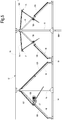
Fig. 3 represents a schematic front view of a portion of greenhouse ofFig. 1 ; -
Fig. 4 represents a schematic front view of some elements of the roof of the greenhouse ofFig. 1 ; -
Fig. 5 represents a schematic front view of a portion of greenhouse varying with respect to that of the preceding figures. - With reference to the previously cited figures, a greenhouse according to the invention is indicated as a whole with the
number 10. - The
greenhouse 10 is provided with aroof 11, which comprises a plurality oftrusses 12 substantially identical to one another, arranged parallel, preferably equidistant, according to the longitudinal direction X, i.e. the depth of the greenhouse, or the direction orthogonal to the plane of the trusses. - Each
truss 12 comprises anupper stringer 13, alower stringer 14,vertical rods 15 anddiagonal rods 16. The connection nodes of stringers and rods are substantially rigid, for example produced by means of plates or sleeves fastened by threaded connections, or also by welding. - Preferably, there are provided two
vertical end rods 15A and one verticalcentral rod 15B. Moreover, there are also provided other intermediatevertical rods 15. - Between subsequent
vertical rods 15, there are provideddiagonal rods 16, arranged sloping in the opposite direction to one another, for example by around 45°, to produce typical substantially triangular truss structures. - More in particular, preferably, the
diagonal rods 16 are fastened by the respective upper ends to thevertical rods 15 and by the respective lower ends to thelower stringers 14. - The
trusses 12 are connected in the longitudinal direction of the greenhouse, bylongitudinal rods 17, for example fastened to the same trusses in the areas in which thediagonal rods 16 are fastened to thevertical rods 15. - Moreover, as better explained below, there are provided
gutters 18 arranged in the longitudinal direction of the greenhouse, fastened to thelower stringers 14 of thetrusses 12, connecting these latter longitudinally to one another. In particular, in this example, the pairs ofdiagonal rods 16 of one truss that converge toward the common area of fastening to thelower stringer 14, are fastened thereto with interposing of a space for housing arespective gutter 18. - Advantageously, the covering of the
roof 11 is arranged between the lower 14 and upper 13 stringers of thetrusses 12, i.e. is produced neither above nor below the trusses. - Preferably, the covering is produced by pairs of substantially flat
adjacent sloping pitches 20, with opposite slope, which provide, in pairs, areas of common convergence at the bottom and upper ridges. The covering is in practice, in this example, a sequence of sloping pitches. It is understood that in other examples the ridges could be produced in the common area of sloping pitches and vertical pitches. The upper ridges are, for example, produced bylongitudinal caps 19 fastened on thelongitudinal rods 17, in practice press formed profiles, on which the pitch coverings are fastened. - Conveniently, in this example, the sloping pitches 20 follow the
diagonal rods 16 of thetrusses 12 and, more in particular, these diagonal rods support thepitches 20. - Preferably, the greenhouse is provided with
means 21 for opening/closing part of the covering of the roof, to allow airing of the greenhouse from above. - With particular reference to
Figs. 1 ,2 and3 , the greenhouse comprises aflexible covering film 22, transparent to light, for example made of PVC. With this film, the opening/closing means 21 comprise aroller 23 for winding of thefilm 22, oriented with its winding axis orthogonal to the planes of thetrusses 12, i.e. parallel to the longitudinal direction X of the greenhouse. These means 21 also comprise a first device for sliding theroller 23 comprising slidingguides 25 associated with thediagonal rods 16 and a second device for rotating theroller 23 to wind/unwind the film, not shown in the figures. In practice, when the covering is open to allow airing of the greenhouse, thefilm 22 associated with aroller 23 is wound on the same roller and the roller is in the upper end of travel position of the slidingguide 25, or the related pitch is "open". An upper edge of thefilm 22 is fastened to a relatedlongitudinal cap 19, while the rest of the film is wound on the roller. Activating the opening/closing means to close the covering, the roller is made to slide downward along theguides 25 and, simultaneously, theroller 23 is made to rotate to unwind the film (an edge is fastened to the ridge of the roof by the longitudinal cap 19), which thus covers the related pitch, producing the covering. Vice versa, to allow opening, the roller is made to rotate and simultaneously slide in the opposite directions to those of closing. - The device for sliding the roller and the device for rotating the roller, and their synchronized operation, are not described or represented in the figures, for simplicity, as they are within the knowledge of those skilled in the art. For example, the axis of the roller can be integral with a toothed wheel meshed with a rack parallel to the
guide 25, and the same axis of the roller can be moved by an actuator along theguide 25, so that during sliding thereon, the toothed wheel is obliged to rotate, performing winding/unwinding of the belt. Naturally, the drive mechanisms that allow movement of the roller can be of manual, or motorized, and therefore automated, type to allow remote control and programming of opening/closing according to time and/or environmental parameters. - The
guides 25 are, for example, produced below by thediagonal rods 16 and above bysecondary oblique rods 16A parallel thereto, for example fastened at an upper end to thevertical rods 15, and at the lower end on thediagonal rods 16, so that therollers 23 are constrained to slide inside the slots defined between said tworods - There are also provided sliding
guides 25A (visible in detail inFig. 4 ), arranged in the areas of the roof between two subsequent trusses, to prevent excessive deformations of the same roller between the trusses, for example formed of two obliquesecondary rods 16B superimposed to define the slots in which the roller slides. These two obliquesecondary rods 16B are, for example, fastened by the ends thereof to thegutters 18 and by the opposite ends to the longitudinal connectingrods 17 of the subsequent trusses. - Preferably, the
roller 23 has a length more or less equal to the longitudinal depth (direction X) of the greenhouse, i.e. of the roof, so that with the movement of a roller it is possible to open or close the whole length of a pitch of the covering. Preferably, there is provided a roller for each pitch. It is understood that it is possible to use rollers with covering films only on some pitches of the roof or also rollers with films that cover only predetermined longitudinal portions of the pitches. -
Fig. 5 shows a variant of the opening/closing means 21 of part of the covering of the roof, which consists of openable windows orhatches 123, for example partially made of polyethylene. Theseopenable windows 123 are tilting according to an axis parallel to the ridges of the sloping pitches. Preferably, window cloths are hinged with reference to their upper side and are provided on the part of the pitch closest to the ridges. For example, for the movement of these windows it is possible to use means 125 that comprise rotary slides with telescoping arms, complete with gear motors. It is clear that the windows can occupy the whole of the longitudinal extension of the pitches, or only part of them. - The covering of the greenhouse can also comprise parts made of
rigid sheets 126, such as inFig. 5 , flat or corrugated or curved, preferably made of material substantially transparent to light, for example glass. - As said, at the bottom of the pitches, at the
lower stringers 14, there are providedgutters 18. -
Cloths 30 for insulating are associated directly with thelower stringers 14, to help to maintain the internal temperature of the greenhouse. In this example there are providedcloths 30 for insulating between eachtruss 12. For example, eachcloth 30 is of a width substantially equal to the length of thetruss 12. It is understood that, in other examples, there can be provided a cloth for insulating that extends in the space between more than two trusses, or a single cloth for the whole greenhouse. Moreover, there can be provided several adjacent (and optionally partially overlapped) cloths, of a width less than the width of the truss, to cover the total width. - There are provided means 31 for movement of the
cloths 30 for insulating, for example drawn by a wire, according to a movement longitudinal to the extension X of the greenhouse, i.e. transverse to the lower stringers. The movement takes place from a stacked back position, preferably folded in a concertina arrangement (as shown in the figures), or rolled up (not shown in the figures), against respective lower stringers, corresponding to a position not in use, to an unrolled position, to cover at least the space up to the subsequent lower stringer (position not shown in the figures) and vice versa. - The
cloths 30 are guided and contained between parallel pairs ofguide elements 32, such as wires, which extend transverse to the lower stringers and, for example, are arranged in contact with the lower and upper face of the lower stringers, so that thecloths 30 are contained in the depth in height of the lower stringers. The movement of the cloths is given, for example, by drawingwires 33 fastened at least to the outer edges of the cloths, moved between guide pulleys 34, fastened to the lower stringers, of which at least one is preferably motorized to allow automated movement of the cloths. - In place of the
cloths 30 for insulating, there can be provided other types of cloths, such as cloths for shading or cloths for reflecting the sun's rays/heat. - Conveniently, in this example, cloths for shading 40 or cloths for reflecting the sun's rays/heat are associated directly with the
upper stringers 13. As for the case of the lower stringers, in this example there are provided cloths for shading 40 between eachtruss 12. For example, eachcloth 40 is of a width substantially equal to the length of thetruss 12. It is understood that in other examples there can be provided acloth 40 for shading that extends in the space between more than two trusses, or a single cloth for shading for the whole greenhouse. Moreover, there can be provided severaladjacent cloths 40 for shading, of a width less than the width of the truss, to cover the total width. - There are provided means 41 for movement of the
cloths 40 for shading, conveniently the same as those associated with thecloths 30 for insulating, associated with theupper stringers 13, for example drawn by a wire, according to a movement longitudinal to the extension X of the greenhouse, i.e. transverse to the upper stringers. The movement takes place from a stacked back position, preferably folded in a concertina arrangement (as shown in the figures), or rolled up (not shown in the figures), against respective lower stringers, corresponding to a position not in use, to an unrolled position, to cover at least the space up to the subsequent upper stringer (position not shown in the figures), and vice versa. - Similarly, the
cloths 40 for shading are guided and contained betweenguide elements 42, such as wires, which extend transverse to the upper stringers and, for example, are arranged in contact at least with the upper face of the upper stringers, and thecloths 40 for shading are contained in the depth in height of the upper stringers. The movement of the cloths is given, for example, by drawingwires 43 fastened at least to the external edges of the cloths, moved between guide pulleys 44, fastened to the upper stringers, one of which is preferably motorized to allow automated movement of the cloths. - From a structural point of view, the greenhouse has a depth, i.e. a longitudinal length according to the direction X, that depends on the number of
trusses 12 used. In practice, given atruss 12, this determines the width of the greenhouse, while the depth is given by the number of trusses. It is understood that it would also be possible to use several trusses arranged adjacent to one another on the same plane and connected, for example, by means of plates and bolts, in practice to produce modular trusses composed of single modules as describe above. - The roof is supported by uprights and, more in particular, the greenhouse comprises, for each
truss 12,lateral uprights 50A aligned with respectivevertical end rods 15A of thetruss 12, adapted to support the same truss. Preferably, there is also provided acentral upright 50B, aligned with the centralvertical axis 15B of the truss. - Along the lateral perimeter of the greenhouse, as is customary, there are preferably provided lateral filling panels, not shown in the figures, for example corrugated panels made of plastic material, transparent sheets or transparent films.
- At least at one of the two lateral uprights, there is provided a reinforcing
structure 55 comprising aportion 56 of rod that is a continuation of thelower stringer 14 of thetruss 12, a firstsloping rod 57 fastened at one end to thelateral upright 50A and at the opposite end to therod portion 56, and a secondsloping rod 58 fastened at one end to the vertical rod and at the opposite end to said rod portion. - It is understood that the drawing only shows possible non-limiting embodiments of the invention, which can vary in forms and arrangements without however departing from the scope of the concept on which the invention is based. Any reference numerals in the appended claims are provided purely to facilitate the reading thereof, in the light of the above description and accompanying drawings, and do not in any way limit the scope of protection.
Claims (15)
- Greenhouse (10) comprising a roof (11) provided with at least two trusses (12) arranged parallel, said trusses comprising an upper stringer (13), a lower stringer (14) and vertical (15, 15A, 15B) and/or diagonal rods (16), characterized in that the covering of said roof (11) is arranged between said lower (14) and upper (13) stringers of said at least two trusses (12).
- Greenhouse according to claim 1, wherein said trusses (12) comprise a plurality of diagonal rods (16) to support sloping covering pitches (20).
- Greenhouse according to claim 2, wherein said trusses (12) comprise a plurality of vertical rods (15, 15A, 15B) for connecting said lower (14) and upper (13) stringers, said diagonal rods (16) being fastened by the respective upper ends to said vertical rods (15, 15A, 15B) and by the respective lower ends to said lower stringers (14).
- Greenhouse according to claim 2 or 3, comprising gutters (18) arranged in the areas of common convergence at the bottom of contiguous pitches (20); preferably, contiguous pairs of said diagonal rods (16) defining the supports of said contiguous pitches being fastened to respective lower stringers (14) with interposing of a space for housing a respective said gutter (18).
- Greenhouse according to one or more of the preceding claims, wherein said covering comprises sloping pitches (20) to define, in pairs of adjacent pitches, areas of common convergence at the bottom and upper ridges, said sloping pitches following said diagonal rods (16) of the truss (12).
- Greenhouse according to one or more of the preceding claims, wherein said covering comprises a flexible covering film (22) at least partially transparent to light and/or sheets made of material at least partially transparent to light.
- Greenhouse according to one or more of the preceding claims, comprising means (21) for opening/closing at least one portion of said covering of said roof (11), to allow airing of the greenhouse from above.
- Greenhouse according to claims 2 and 7, wherein said covering comprises a flexible covering film (22) at least partially transparent to light; said opening/closing means (21) comprising:- a roller (23) for winding said film (22), oriented with its winding axis orthogonal to the planes of the trusses (12),- a device for sliding said roller along corresponding guides (25) associated with said trusses (12),- a device for rotating said roller (239 to wind/unwind the film (22),so that said roller (23) is adapted to slide downward along said corresponding guides (25) and simultaneously to rotate on its axis to unwind the film (22), and vice versa, to slide upward along said guides (25) and simultaneously to rotate on its axis to wind said film (22).
- Greenhouse according to claims 5 and 8, wherein said guides (25) are produced along respective diagonal rods (16) of said truss. (12)
- Greenhouse according to claim 7, wherein said opening/closing means (21) of at least one portion of said covering of said roof comprise openable windows (123).
- Greenhouse according to claims 5 and 10, wherein said openable windows (123) are tilting according to an axis parallel to the ridges of the sloping pitches.
- Greenhouse according to one or more of the preceding claims, comprising at least one cloth (30, 40) for insulating and/or shading and/or reflecting the sun's rays/heat associated directly with one or more of the lower stringers (14) of said trusses 812) and/or to one or more of the upper stringers (13) of said trusses (14).
- Greenhouse according to claim 12, comprising at least three of said trusses (12) placed side by side correspondingly, there being provided at least a first cloth (30) between a first pair of lower stringers (14) and at least a second cloth (30) between the subsequent pair of lower stringers, and/or at least one cloth (40) between a first pair of upper stringers and at least a further cloth (40) between the second pair of upper stringers (13).
- Greenhouse according to claim 12 or 13, comprising means for movement (33, 34, 41), preferably drawn by a wire, of said at least one cloth (30, 40) arranged transverse to the stringers (13, 14) with which it is associated; preferably, said at least one cloth is moved from a stacked back position, preferably folded in a concertina arrangement, or rolled up, against a lower or upper stringer, corresponding to a position not in use, to an unrolled position, to cover at least the space up to the subsequent lower or upper stringer, and vice versa.
- Greenhouse according to one or more of the preceding claims, comprising, for each truss (12), lateral uprights (50A) aligned with respective vertical end rods (15A) of the truss (12), adapted to support said trusses; at least at one of the two lateral uprights (50A), there being provided a reinforcing structure (55) comprising a portion of rod as an continuation of the lower stringer of the truss, a first sloping rod fastened at one end to said upright and at the opposite end to said portion of rod, and a second sloping rod fastened at one end to said vertical rod and at the opposite end to said portion of rod.
Applications Claiming Priority (2)
| Application Number | Priority Date | Filing Date | Title |
|---|---|---|---|
| ITFI20150066 | 2015-03-10 | ||
| PCT/IB2016/051340 WO2016142883A1 (en) | 2015-03-10 | 2016-03-09 | Greenhouse |
Publications (2)
| Publication Number | Publication Date |
|---|---|
| EP3268552A1 EP3268552A1 (en) | 2018-01-17 |
| EP3268552B1 true EP3268552B1 (en) | 2019-02-27 |
Family
ID=53189890
Family Applications (1)
| Application Number | Title | Priority Date | Filing Date |
|---|---|---|---|
| EP16723821.1A Active EP3268552B1 (en) | 2015-03-10 | 2016-03-09 | Greenhouse |
Country Status (2)
| Country | Link |
|---|---|
| EP (1) | EP3268552B1 (en) |
| WO (1) | WO2016142883A1 (en) |
Families Citing this family (1)
| Publication number | Priority date | Publication date | Assignee | Title |
|---|---|---|---|---|
| CN114766251B (en) * | 2022-02-28 | 2023-05-05 | 无锡职业技术学院 | Energy-saving wind-proof sand-controlling movable greenhouse |
Family Cites Families (3)
| Publication number | Priority date | Publication date | Assignee | Title |
|---|---|---|---|---|
| FR2137124A1 (en) * | 1971-05-07 | 1972-12-29 | Schmitt Jose | |
| DE2502670A1 (en) * | 1975-01-23 | 1976-08-26 | Georg Dipl Ing Hoentsch | Roof comprising triangular elements for greenhouses - with through ventilation, heating and dust suppression |
| US5655335A (en) * | 1995-07-07 | 1997-08-12 | Vermeer; Arthur Anthony | Greenhouse structures and roof structures therefor |
-
2016
- 2016-03-09 WO PCT/IB2016/051340 patent/WO2016142883A1/en not_active Ceased
- 2016-03-09 EP EP16723821.1A patent/EP3268552B1/en active Active
Non-Patent Citations (1)
| Title |
|---|
| None * |
Also Published As
| Publication number | Publication date |
|---|---|
| WO2016142883A1 (en) | 2016-09-15 |
| EP3268552A1 (en) | 2018-01-17 |
Similar Documents
| Publication | Publication Date | Title |
|---|---|---|
| US5564234A (en) | Building structure consisting of a framework of uprights and beams covered with a foil | |
| US11060296B2 (en) | Modular multifunction shading device, particularly for a pergola | |
| US10858840B2 (en) | Electric blinds roof structure of canopy and canopy | |
| KR102481550B1 (en) | Thermal and Daylighting System for Energy Saving in Greenhouse | |
| US11653602B2 (en) | Adjustable shade house driven by pulleys | |
| US20150013238A1 (en) | Covering device having sliding cover elements | |
| KR101066091B1 (en) | The outside shading for greenhouse | |
| EP4330489B1 (en) | Roof arrangement for a terrace canopy and terrace canopy comprising the roof arrangement | |
| CH712622A2 (en) | Covering apparatus. | |
| EP4232653B1 (en) | Roof construction for a terrace canopy, kit of parts for assembling the roof construction, and terrace canopy comprising the roof construction | |
| CN105453951A (en) | Multi-span greenhouse roof with functions of lighting, heat preservation, ventilation and sunshading | |
| US12414535B2 (en) | Retractable curtain for livestock structures | |
| EP3268552B1 (en) | Greenhouse | |
| EP3018284A1 (en) | Winding device for covering openings of a building | |
| EP0089657A1 (en) | Insulating curtain | |
| US10004180B1 (en) | Modular enclosure with automated curtain deployment | |
| EP1250835B1 (en) | Greenhouse | |
| WO2009106089A1 (en) | Housing system | |
| US4608788A (en) | Adjustable overhang panel for building eave | |
| DE102012221860B4 (en) | awning | |
| WO2003012240A1 (en) | Pneumatic roller blind | |
| DE202018102937U1 (en) | Glasshouse | |
| WO2022185125A1 (en) | Canopy roofing system | |
| JPS5920037Y2 (en) | Greenhouse with shading device | |
| CN214282404U (en) | A sliding-type greenhouse thermal insulation system |
Legal Events
| Date | Code | Title | Description |
|---|---|---|---|
| STAA | Information on the status of an ep patent application or granted ep patent |
Free format text: STATUS: THE INTERNATIONAL PUBLICATION HAS BEEN MADE |
|
| PUAI | Public reference made under article 153(3) epc to a published international application that has entered the european phase |
Free format text: ORIGINAL CODE: 0009012 |
|
| STAA | Information on the status of an ep patent application or granted ep patent |
Free format text: STATUS: REQUEST FOR EXAMINATION WAS MADE |
|
| 17P | Request for examination filed |
Effective date: 20170905 |
|
| AK | Designated contracting states |
Kind code of ref document: A1 Designated state(s): AL AT BE BG CH CY CZ DE DK EE ES FI FR GB GR HR HU IE IS IT LI LT LU LV MC MK MT NL NO PL PT RO RS SE SI SK SM TR |
|
| AX | Request for extension of the european patent |
Extension state: BA ME |
|
| DAV | Request for validation of the european patent (deleted) | ||
| DAX | Request for extension of the european patent (deleted) | ||
| GRAP | Despatch of communication of intention to grant a patent |
Free format text: ORIGINAL CODE: EPIDOSNIGR1 |
|
| STAA | Information on the status of an ep patent application or granted ep patent |
Free format text: STATUS: GRANT OF PATENT IS INTENDED |
|
| INTG | Intention to grant announced |
Effective date: 20180917 |
|
| GRAS | Grant fee paid |
Free format text: ORIGINAL CODE: EPIDOSNIGR3 |
|
| GRAA | (expected) grant |
Free format text: ORIGINAL CODE: 0009210 |
|
| STAA | Information on the status of an ep patent application or granted ep patent |
Free format text: STATUS: THE PATENT HAS BEEN GRANTED |
|
| AK | Designated contracting states |
Kind code of ref document: B1 Designated state(s): AL AT BE BG CH CY CZ DE DK EE ES FI FR GB GR HR HU IE IS IT LI LT LU LV MC MK MT NL NO PL PT RO RS SE SI SK SM TR |
|
| REG | Reference to a national code |
Ref country code: GB Ref legal event code: FG4D |
|
| REG | Reference to a national code |
Ref country code: CH Ref legal event code: EP |
|
| REG | Reference to a national code |
Ref country code: DE Ref legal event code: R096 Ref document number: 602016010431 Country of ref document: DE |
|
| REG | Reference to a national code |
Ref country code: AT Ref legal event code: REF Ref document number: 1101539 Country of ref document: AT Kind code of ref document: T Effective date: 20190315 |
|
| REG | Reference to a national code |
Ref country code: IE Ref legal event code: FG4D |
|
| REG | Reference to a national code |
Ref country code: NL Ref legal event code: MP Effective date: 20190227 |
|
| REG | Reference to a national code |
Ref country code: LT Ref legal event code: MG4D |
|
| PG25 | Lapsed in a contracting state [announced via postgrant information from national office to epo] |
Ref country code: SE Free format text: LAPSE BECAUSE OF FAILURE TO SUBMIT A TRANSLATION OF THE DESCRIPTION OR TO PAY THE FEE WITHIN THE PRESCRIBED TIME-LIMIT Effective date: 20190227 Ref country code: NL Free format text: LAPSE BECAUSE OF FAILURE TO SUBMIT A TRANSLATION OF THE DESCRIPTION OR TO PAY THE FEE WITHIN THE PRESCRIBED TIME-LIMIT Effective date: 20190227 Ref country code: LT Free format text: LAPSE BECAUSE OF FAILURE TO SUBMIT A TRANSLATION OF THE DESCRIPTION OR TO PAY THE FEE WITHIN THE PRESCRIBED TIME-LIMIT Effective date: 20190227 Ref country code: FI Free format text: LAPSE BECAUSE OF FAILURE TO SUBMIT A TRANSLATION OF THE DESCRIPTION OR TO PAY THE FEE WITHIN THE PRESCRIBED TIME-LIMIT Effective date: 20190227 Ref country code: PT Free format text: LAPSE BECAUSE OF FAILURE TO SUBMIT A TRANSLATION OF THE DESCRIPTION OR TO PAY THE FEE WITHIN THE PRESCRIBED TIME-LIMIT Effective date: 20190627 Ref country code: NO Free format text: LAPSE BECAUSE OF FAILURE TO SUBMIT A TRANSLATION OF THE DESCRIPTION OR TO PAY THE FEE WITHIN THE PRESCRIBED TIME-LIMIT Effective date: 20190527 |
|
| PG25 | Lapsed in a contracting state [announced via postgrant information from national office to epo] |
Ref country code: BG Free format text: LAPSE BECAUSE OF FAILURE TO SUBMIT A TRANSLATION OF THE DESCRIPTION OR TO PAY THE FEE WITHIN THE PRESCRIBED TIME-LIMIT Effective date: 20190527 Ref country code: GR Free format text: LAPSE BECAUSE OF FAILURE TO SUBMIT A TRANSLATION OF THE DESCRIPTION OR TO PAY THE FEE WITHIN THE PRESCRIBED TIME-LIMIT Effective date: 20190528 Ref country code: LV Free format text: LAPSE BECAUSE OF FAILURE TO SUBMIT A TRANSLATION OF THE DESCRIPTION OR TO PAY THE FEE WITHIN THE PRESCRIBED TIME-LIMIT Effective date: 20190227 Ref country code: IS Free format text: LAPSE BECAUSE OF FAILURE TO SUBMIT A TRANSLATION OF THE DESCRIPTION OR TO PAY THE FEE WITHIN THE PRESCRIBED TIME-LIMIT Effective date: 20190627 Ref country code: RS Free format text: LAPSE BECAUSE OF FAILURE TO SUBMIT A TRANSLATION OF THE DESCRIPTION OR TO PAY THE FEE WITHIN THE PRESCRIBED TIME-LIMIT Effective date: 20190227 Ref country code: HR Free format text: LAPSE BECAUSE OF FAILURE TO SUBMIT A TRANSLATION OF THE DESCRIPTION OR TO PAY THE FEE WITHIN THE PRESCRIBED TIME-LIMIT Effective date: 20190227 |
|
| REG | Reference to a national code |
Ref country code: AT Ref legal event code: MK05 Ref document number: 1101539 Country of ref document: AT Kind code of ref document: T Effective date: 20190227 |
|
| PG25 | Lapsed in a contracting state [announced via postgrant information from national office to epo] |
Ref country code: CZ Free format text: LAPSE BECAUSE OF FAILURE TO SUBMIT A TRANSLATION OF THE DESCRIPTION OR TO PAY THE FEE WITHIN THE PRESCRIBED TIME-LIMIT Effective date: 20190227 Ref country code: AL Free format text: LAPSE BECAUSE OF FAILURE TO SUBMIT A TRANSLATION OF THE DESCRIPTION OR TO PAY THE FEE WITHIN THE PRESCRIBED TIME-LIMIT Effective date: 20190227 Ref country code: RO Free format text: LAPSE BECAUSE OF FAILURE TO SUBMIT A TRANSLATION OF THE DESCRIPTION OR TO PAY THE FEE WITHIN THE PRESCRIBED TIME-LIMIT Effective date: 20190227 Ref country code: ES Free format text: LAPSE BECAUSE OF FAILURE TO SUBMIT A TRANSLATION OF THE DESCRIPTION OR TO PAY THE FEE WITHIN THE PRESCRIBED TIME-LIMIT Effective date: 20190227 Ref country code: EE Free format text: LAPSE BECAUSE OF FAILURE TO SUBMIT A TRANSLATION OF THE DESCRIPTION OR TO PAY THE FEE WITHIN THE PRESCRIBED TIME-LIMIT Effective date: 20190227 Ref country code: SK Free format text: LAPSE BECAUSE OF FAILURE TO SUBMIT A TRANSLATION OF THE DESCRIPTION OR TO PAY THE FEE WITHIN THE PRESCRIBED TIME-LIMIT Effective date: 20190227 Ref country code: DK Free format text: LAPSE BECAUSE OF FAILURE TO SUBMIT A TRANSLATION OF THE DESCRIPTION OR TO PAY THE FEE WITHIN THE PRESCRIBED TIME-LIMIT Effective date: 20190227 |
|
| REG | Reference to a national code |
Ref country code: CH Ref legal event code: PL |
|
| REG | Reference to a national code |
Ref country code: DE Ref legal event code: R097 Ref document number: 602016010431 Country of ref document: DE |
|
| PG25 | Lapsed in a contracting state [announced via postgrant information from national office to epo] |
Ref country code: PL Free format text: LAPSE BECAUSE OF FAILURE TO SUBMIT A TRANSLATION OF THE DESCRIPTION OR TO PAY THE FEE WITHIN THE PRESCRIBED TIME-LIMIT Effective date: 20190227 Ref country code: SM Free format text: LAPSE BECAUSE OF FAILURE TO SUBMIT A TRANSLATION OF THE DESCRIPTION OR TO PAY THE FEE WITHIN THE PRESCRIBED TIME-LIMIT Effective date: 20190227 Ref country code: LU Free format text: LAPSE BECAUSE OF NON-PAYMENT OF DUE FEES Effective date: 20190309 |
|
| PG25 | Lapsed in a contracting state [announced via postgrant information from national office to epo] |
Ref country code: AT Free format text: LAPSE BECAUSE OF FAILURE TO SUBMIT A TRANSLATION OF THE DESCRIPTION OR TO PAY THE FEE WITHIN THE PRESCRIBED TIME-LIMIT Effective date: 20190227 Ref country code: MC Free format text: LAPSE BECAUSE OF FAILURE TO SUBMIT A TRANSLATION OF THE DESCRIPTION OR TO PAY THE FEE WITHIN THE PRESCRIBED TIME-LIMIT Effective date: 20190227 |
|
| PLBE | No opposition filed within time limit |
Free format text: ORIGINAL CODE: 0009261 |
|
| STAA | Information on the status of an ep patent application or granted ep patent |
Free format text: STATUS: NO OPPOSITION FILED WITHIN TIME LIMIT |
|
| PG25 | Lapsed in a contracting state [announced via postgrant information from national office to epo] |
Ref country code: LI Free format text: LAPSE BECAUSE OF NON-PAYMENT OF DUE FEES Effective date: 20190331 Ref country code: CH Free format text: LAPSE BECAUSE OF NON-PAYMENT OF DUE FEES Effective date: 20190331 Ref country code: IE Free format text: LAPSE BECAUSE OF NON-PAYMENT OF DUE FEES Effective date: 20190309 |
|
| 26N | No opposition filed |
Effective date: 20191128 |
|
| PG25 | Lapsed in a contracting state [announced via postgrant information from national office to epo] |
Ref country code: SI Free format text: LAPSE BECAUSE OF FAILURE TO SUBMIT A TRANSLATION OF THE DESCRIPTION OR TO PAY THE FEE WITHIN THE PRESCRIBED TIME-LIMIT Effective date: 20190227 |
|
| PG25 | Lapsed in a contracting state [announced via postgrant information from national office to epo] |
Ref country code: TR Free format text: LAPSE BECAUSE OF FAILURE TO SUBMIT A TRANSLATION OF THE DESCRIPTION OR TO PAY THE FEE WITHIN THE PRESCRIBED TIME-LIMIT Effective date: 20190227 |
|
| PG25 | Lapsed in a contracting state [announced via postgrant information from national office to epo] |
Ref country code: MT Free format text: LAPSE BECAUSE OF NON-PAYMENT OF DUE FEES Effective date: 20190309 |
|
| GBPC | Gb: european patent ceased through non-payment of renewal fee |
Effective date: 20200309 |
|
| PG25 | Lapsed in a contracting state [announced via postgrant information from national office to epo] |
Ref country code: GB Free format text: LAPSE BECAUSE OF NON-PAYMENT OF DUE FEES Effective date: 20200309 |
|
| PG25 | Lapsed in a contracting state [announced via postgrant information from national office to epo] |
Ref country code: CY Free format text: LAPSE BECAUSE OF FAILURE TO SUBMIT A TRANSLATION OF THE DESCRIPTION OR TO PAY THE FEE WITHIN THE PRESCRIBED TIME-LIMIT Effective date: 20190227 |
|
| PG25 | Lapsed in a contracting state [announced via postgrant information from national office to epo] |
Ref country code: HU Free format text: LAPSE BECAUSE OF FAILURE TO SUBMIT A TRANSLATION OF THE DESCRIPTION OR TO PAY THE FEE WITHIN THE PRESCRIBED TIME-LIMIT; INVALID AB INITIO Effective date: 20160309 |
|
| PGFP | Annual fee paid to national office [announced via postgrant information from national office to epo] |
Ref country code: FR Payment date: 20220325 Year of fee payment: 7 |
|
| PG25 | Lapsed in a contracting state [announced via postgrant information from national office to epo] |
Ref country code: MK Free format text: LAPSE BECAUSE OF FAILURE TO SUBMIT A TRANSLATION OF THE DESCRIPTION OR TO PAY THE FEE WITHIN THE PRESCRIBED TIME-LIMIT Effective date: 20190227 |
|
| PG25 | Lapsed in a contracting state [announced via postgrant information from national office to epo] |
Ref country code: FR Free format text: LAPSE BECAUSE OF NON-PAYMENT OF DUE FEES Effective date: 20230331 |
|
| PGFP | Annual fee paid to national office [announced via postgrant information from national office to epo] |
Ref country code: DE Payment date: 20260320 Year of fee payment: 11 |
|
| PGFP | Annual fee paid to national office [announced via postgrant information from national office to epo] |
Ref country code: BE Payment date: 20260323 Year of fee payment: 11 Ref country code: IT Payment date: 20260226 Year of fee payment: 11 |