EP3268318B1 - Bepflanztes biologisches system ohne drainage zur behandlung von verunreinigtem wasser - Google Patents
Bepflanztes biologisches system ohne drainage zur behandlung von verunreinigtem wasser Download PDFInfo
- Publication number
- EP3268318B1 EP3268318B1 EP16764267.7A EP16764267A EP3268318B1 EP 3268318 B1 EP3268318 B1 EP 3268318B1 EP 16764267 A EP16764267 A EP 16764267A EP 3268318 B1 EP3268318 B1 EP 3268318B1
- Authority
- EP
- European Patent Office
- Prior art keywords
- installation
- installation according
- distributing pipe
- excavation
- soil
- Prior art date
- Legal status (The legal status is an assumption and is not a legal conclusion. Google has not performed a legal analysis and makes no representation as to the accuracy of the status listed.)
- Active
Links
Images



Classifications
-
- C—CHEMISTRY; METALLURGY
- C02—TREATMENT OF WATER, WASTE WATER, SEWAGE, OR SLUDGE
- C02F—TREATMENT OF WATER, WASTE WATER, SEWAGE, OR SLUDGE
- C02F3/00—Biological treatment of water, waste water, or sewage
- C02F3/32—Biological treatment of water, waste water, or sewage characterised by the animals or plants used, e.g. algae
-
- C—CHEMISTRY; METALLURGY
- C02—TREATMENT OF WATER, WASTE WATER, SEWAGE, OR SLUDGE
- C02F—TREATMENT OF WATER, WASTE WATER, SEWAGE, OR SLUDGE
- C02F3/00—Biological treatment of water, waste water, or sewage
- C02F3/02—Aerobic processes
- C02F3/04—Aerobic processes using trickle filters
- C02F3/046—Soil filtration
-
- C—CHEMISTRY; METALLURGY
- C02—TREATMENT OF WATER, WASTE WATER, SEWAGE, OR SLUDGE
- C02F—TREATMENT OF WATER, WASTE WATER, SEWAGE, OR SLUDGE
- C02F3/00—Biological treatment of water, waste water, or sewage
-
- C—CHEMISTRY; METALLURGY
- C02—TREATMENT OF WATER, WASTE WATER, SEWAGE, OR SLUDGE
- C02F—TREATMENT OF WATER, WASTE WATER, SEWAGE, OR SLUDGE
- C02F3/00—Biological treatment of water, waste water, or sewage
- C02F3/32—Biological treatment of water, waste water, or sewage characterised by the animals or plants used, e.g. algae
- C02F3/327—Biological treatment of water, waste water, or sewage characterised by the animals or plants used, e.g. algae characterised by animals and plants
-
- C—CHEMISTRY; METALLURGY
- C02—TREATMENT OF WATER, WASTE WATER, SEWAGE, OR SLUDGE
- C02F—TREATMENT OF WATER, WASTE WATER, SEWAGE, OR SLUDGE
- C02F2203/00—Apparatus and plants for the biological treatment of water, waste water or sewage
- C02F2203/006—Apparatus and plants for the biological treatment of water, waste water or sewage details of construction, e.g. specially adapted seals, modules, connections
-
- Y—GENERAL TAGGING OF NEW TECHNOLOGICAL DEVELOPMENTS; GENERAL TAGGING OF CROSS-SECTIONAL TECHNOLOGIES SPANNING OVER SEVERAL SECTIONS OF THE IPC; TECHNICAL SUBJECTS COVERED BY FORMER USPC CROSS-REFERENCE ART COLLECTIONS [XRACs] AND DIGESTS
- Y02—TECHNOLOGIES OR APPLICATIONS FOR MITIGATION OR ADAPTATION AGAINST CLIMATE CHANGE
- Y02W—CLIMATE CHANGE MITIGATION TECHNOLOGIES RELATED TO WASTEWATER TREATMENT OR WASTE MANAGEMENT
- Y02W10/00—Technologies for wastewater treatment
- Y02W10/10—Biological treatment of water, waste water, or sewage
Definitions
- the present innovation concerns a planted, biological system without drainage for treatment of contaminated water.
- the installation is subsequently planted on each side of the plastic cassettes with 6 rows of willow clones with different characteristics. These installations are known in widths of 4, 6 and 8 meters.
- the distributing pipe will be more easily accessible, should this become clogged, since it has not been sunk deeply.
- the accessibility is further increased, once the planting according to a preferred implementation has been provided around the central excavation and not above, as in the prior art. This accessibility will also be significant, if the decommissioning of an installation is desired, for instance at end of life, since all the non biodegradable material, except from various wells, is found at the surface. Thus, there will be no considerable amount of deep plastic materials in need of removal.
- the distributing pipe comprises elastic, self-sealing lips, which mainly extend in a longitudinal direction of the distributing pipe.
- elastic, self-sealing lips have proven to be suitable for the passing of larger, solid contamination parts, which may have evaded the grinding.
- the selected biomass is straw, preferably in the shape of bales.
- Straw is inexpensive and has a suitable porosity for seepage of the water, and furthermore allows for a certain storage of the water.
- bales of straw are regular items, which allow for an easy placement in an elongated excavation.
- the excavation is lined with a fiber cloth. This is placed between the repositioned soil and the waterproof membrane, by which the risk of cutting of the waterproof membrane is reduced. It is furthermore prevented, that the surrounding soil will eventually move to the middle of the installation, as the bales of straw are decomposed over time.
- the fiber cloth can be fixed to the mesh reinforcement prevent this from sliding to the middle of the installation. Vertical slots are provided in the lower 1/3 of the fiber cloth, so that the root system of the planting can penetrate to the seeping nutrients from the waste water.
- the planting comprises willow (Salix) and/or alder (Alnus glutinosa).
- willow Salix
- alder Alnus glutinosa
- the excavation is covered by a mesh reinforcement.
- the mesh reinforcement serves the purpose of mounting the distributing pipe and securing its position, once the biomass within the excavation collapses over time. Furthermore, a cavity is under the mesh reinforcement is hereby obtained, which covers the excavation, and which in turn ensures that the roots from the planting around the excavation do not intrude and clog the feeding pipe.
- the mesh reinforcement is vaulted, since it will then better support the weight of the layer of soil covering the distributing pipe, according to yet another implementation. For this canopy, the removed soil from the excavation can be employed with advantage.
- An installation is illustrated according to the invention, with fig. 1 as the point of departure.
- an elongated embankment 30 with a planting 31 in each side is shown in bird's eye view.
- the planting 31 is preferably a fast growing tree species, such as willow (Salix).
- This planting could also be willow, but in order to demonstrate an alternative, has been illustrated in the shape of alder (Alnus glutinosa).
- the plantings 31 and 32 are not limited to these species, but could comprise of other tree species, or consist of a mixed planting of several species, e.g. a mixture of willow and alder.
- a manhole 21 is seen at the end of the elongated embankment.
- the manhole is shown in detail in fig. 2 , illustrating a cross section through a first embodiment of an installation according to the invention.
- the installation is established in an excavation 33.
- the width of the excavation is typically 4 - 6 m.
- the purification capacity can be adjusted by a corresponding adjustment of the length, which could for instance be 50 m, but in principle, the length has no limitation.
- the excavation 33 itself is lined as in the prior art with fiber cloth 2 and a waterproof membrane 1.
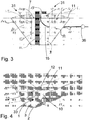
- a layer of soil can be laid down as shown in fig. 3 and 4 , or sand 3 has been replaced in the bottom of the excavation.
- a core of selected biomass has been placed over the layer of soil or sand 3, such as compressed straw in the shape of a row of bales 4, which has been lowered longitudinally for the length of the excavation.
- the sides of the bales are covered with fiber textile 7 or a net, which has been placed over half of the sides of the bales prior to the repositioning of soil, in order to prevent the surrounding soil from moving to the middle of the installation over time.
- This fiber textile 7 or net is preferably fixed to the mesh reinforcement 12, so that is position is secured, when over time the surrounding soil moves to the middle of the installation.
- the fiber cloth 7 is placed over the aligned layer of soil or sand 3 according to the invention, as is illustrated in the best way in fig. 4 .
- a number of vertical slots 9 are cut into the bottom 1/3, typically corresponding to 50 cm, with an intermediate distance between them throughout the entire length, so that the willow roots can also work their way into the middle of the installation over time.
- the activity and transport of oxygen of the willow roots into the installation reduces the development of hydrogen sulfide. Simultaneously, the biodegradability process is considerably enhanced.
- the soil 10 is repositioned until the stowage reaches the height of the bales 4, where it is aligned, and the flap, which was placed over half of the bales is then placed over the aligned soil 11.
- a number of coated mesh reinforcements 12 have been placed over the aligned layer of soil 11, so that they cover pales the alignment and the flap of the fiber textile.
- the distributing pipe 13 has lip-shaped, longitudinal cuts in the shape of slots 34, so that lips 35 are formed, and is mounted at the mesh reinforcement 12 with these cuts pointing downwards and longitudinally in the installation.
- the distributing pipe is connected to the discharge pipe 15 on a grinder pump 36.
- the grinder pump 36 can be placed in a wet well in connection with the installation, but in principle could also be placed elsewhere at a distance from the installation or in one of the manholes 21. Regardless of the placement, the grinder pump 36 is however always placed at a lower position than the distributing pipe 13.
- the mesh reinforcements can be fixed with a suitable number of plugs 16, or the ends can be bent by 90 degrees into the aligned layer of soil. Subsequently, a fiber cloth 18 is placed over the mesh reinforcements 12 for the entire length of the installation. Fiber cloth 18 and mesh reinforcement 12 is covered with soil, preferably by repostioning the remainder of the dug out soil, so that the middle of the installation is taller than the external part of the installation.
- the distributing pipe 13 has an elastic and flexible wall, which, as mentioned, has a number of longitudinal slots 34, and thereby differs from the above mentioned art, which has a relatively hard wall with a number of non-elastic, circular holes.
- the distributing pipe 13 has longitudinal lips underneath, which open and close themselves automatically during the discharge of the blended wastewater from the grinder pump 36 due to the elasticity and the pump pressure, and allows for larger particles to be discharged into the installation. Once the pump pressure and discharge have been completed, the lips will close again. Since a cavity above the bales of straw 4 will be formed over time, once these are decomposed under the mesh reinforcement 12, the larger particles will easily be able to pass away from the distributing pipe 13.
- bales of straw 4 furthermore offer the advantage, that the heat from the biological decomposition will rise and heat the distributing pipe 13. A freezing of the distributing pipe 13 is hereby prevented, even if this is placed relatively close to the surface, which has been an issue in the prior art. This phenomenon will not occur here, where warm air from the system will insulate and supply heat to the pipe.
- the inlet pipe 15 is lower than the distributing pipe 13, as illustrated in fig. 2 and 3 . Therefore, the inlet pipe 15 will be discharged at the back flow, once the pump 36 stops.
- a manhole 21 with holes and surrounding fiber cloth is mounted at each end of the installation.
- the terminal points of the distributing pipe is led to the manhole and is sealed with a suitable plug valve 23.
- the distributing pipe 13 can be flushed if necessary, should this be clogged, contrary to expectation.
- the black waste water or slurry is fed directly via a grinder pump 36 without septic tank to a flexible distributing pipe 13 for the entire length of the installation, which is equipped with longitudinal, self-sealing, and elastic, lip-shaped, downwards pointing slots/slits 34, instead of circular holes, which would be clogged.
- the configuration with elastic, lip-shaped slots 34 in the distributing pipe 13 means, that non-blended lumps such as micro plastics, or not entirely grinded segments, by an accumulation in the opening of the slot would open the flexible lips 35 as shown in fig.
- the longitudinal slots/slits 34 has varying lengths and distances between them, depending on the pressure drop in the distributing pipe 13, so that the same amount is pumped out per running meter at the ends, as in the center of the installation, where the pressure is at its highest.
- Another benefit, which, according to the invention, is achieved by configuring the plastic distributing pipe 13 with the longitudinal, downwards pointing lips, that close again after the drainage, is that the roots of the planting, for instance willow or alder, only can penetrate into the pipe with great difficulty, even after several years of operation.
- the argument for employing for instance bales in the middle of the installation, instead of plastic cassettes, is the price.
- a casing is achieved, where the fiber cloth as well as the rionet during establishment can be supported during the filling of soil in the rest of the installation.
- the non-decomposable types of micro plastics, medicines and estrogens according to the invention are deposited in the installation, and blended with the soil particles of the installation, where the chance of a total or partial decomposition as the result of a long-term, biological activity during the operating life of the installation is substantial.
- bales according to the invention optimizes the decomposition of substances, the seeping through the bales and the blending to enhance the C/N-ratio, which supplies the installation with 80 - 100 atoms of carbon for each 8 - 10 atoms of nitrogen from the waste water.
- the root system of the willow clones transport oxygen so that the nitrification process of ammonium, NH4+ to nitrite(NO2-) to nitrate (NO3-) can take place.
- Alder is capable of binding nitrogen-fixing bacteria and using hemoglobin of aerating the nitrogen to nitrogenous compounds that are usable for the planting.
- the use of an inexpensive, biodegradable, carbonaceous material such as bales results in a large pore volume in the installation from the beginning, and as this is gradually decomposed, the root system from the existing willow clones/alder in the plating of the installation will work their way into the mineralized, composted mass, though a number of vertical cuttings of the fiber cloth 9 and into the bales with an suitable space for the entire length of the installation.
- the mesh reinforcements 12 which are corrosion protected and have been placed in the installation and fixed with plugs 16, be maintained within the installation as the root system of the willow clones and the willow clones themselves are established, so that the amount of soil above the mesh reinforcements can be extended as the installation settles.
- the manholes 21 at the end can be mounted with a T-fitting 14 in a suitable distance under the mesh reinforcements 12 and into the biomass.
- the purpose of this T-fitting is to open the possibility for ventilating the biomass as this is decomposed, by ventilating the installation through the manholes, should this be desired.
- the planting of the installation with willow clones/alder is most appropriately carried out in rows of 2x2 on each side of the center axis. It is then possible to harvest each side mechanically, for example every 3 - 4 years.
- volume that the waste water can achieve is 3 - 4 times larger as a result of the straw, which contains more air than soil, and thereby a larger pore volume.
- the biological heating which, according to the invention, is started by the waste water in the bales, can reach up to 70 degrees Celcius, and according to the invention, will provide a strongly enhanced initial growth to the area with the willow clones, where the soil will reach 20 - 30 degrees Celcius, instead of the 8 - 10 degrees in the prior art.
- the entire installation can hereafter be planted with a low-growing species of grass, which will compete with shrubs, as it will be stimulated by the heat of the biological activity within the installation, or with a type of biodegradable corn plastic, placed in transverse strips that stops the growth of shrubs, in order for the rain water to reach the willow sets.
- the two sides are subsequently planted with willow sets/alder, which, contrary to the prior art, must have a double length, so that it also penetrates the fiber textile in the inner row.
- a variation of the invention could be a mixture of leca or styropore balls in the soil at the middle of the installation in order to decrease the pressure on the mesh reinforcement 12, once the bales 4 are decomposed/composted together with the waste water.
- vaulted mesh reinforcement 12 As shown in fig. 5 and 6 , where the vaulted shape strengthens the mesh reinforcement 12 as compared to the flat mesh reinforcement 12 in fig. 1-4 . Furthermore, the use of vaulted mesh reinforcements 12 entails, that a canopy with soil and especially fiber cloth is and will continue to be vaulted. Thus, rain water will be more able to drain off from the sides and benefit the planting, instead of penetrating and straining the central part of the installation with unnecessary amounts of water.
- the invention concerns a low-energy, planted biological installation for conversion/purification/depositing of black waste water or slurry without drainage. Characterized by not being connected to septic tank, but is fed via a wet well directly with blended, black waste water from a grinder pump, via a distributing pipe with elastic, self-sealing, longitudinal lips, where a biomass placed in the upper side of the installation is supplied with the blended waste water. The following is thereby provided:
Landscapes
- Life Sciences & Earth Sciences (AREA)
- Engineering & Computer Science (AREA)
- Water Supply & Treatment (AREA)
- Hydrology & Water Resources (AREA)
- Microbiology (AREA)
- Environmental & Geological Engineering (AREA)
- Biodiversity & Conservation Biology (AREA)
- Chemical & Material Sciences (AREA)
- Organic Chemistry (AREA)
- Biotechnology (AREA)
- Botany (AREA)
- Cultivation Of Plants (AREA)
- Cultivation Receptacles Or Flower-Pots, Or Pots For Seedlings (AREA)
- Purification Treatments By Anaerobic Or Anaerobic And Aerobic Bacteria Or Animals (AREA)
Claims (10)
- Bepflanzte, biologische Installation ohne Drainage zur Behandlung von verunreinigtem Wasser, umfassend eine Bepflanzung (31), die eine oder mehrere ausgewählte Baumart(en) umfasst, wobei die bepflanzte, biologische Installation dadurch gekennzeichnet ist, dass sie mit keinem Klärtank verbunden ist, und dass sie Folgendes umfasst:einen zentralen Ausgrabungsteil (33), der mit einer ausgewählten Biomasse (4) gefüllt ist,eine Pumpe (36), die zum Zerkleinern von festen Verunreinigungen in dem verunreinigten Wasser ausgestaltet ist, undmindestens eine Verteilerleitung (13), die elastische, selbstdichtende Lippen (35, 35) umfasst, die sich bezüglich der Verteilerleitung (13) in Längsrichtung erstrecken, die mit der Pumpe (36) verbunden ist und zum Zuführen des verunreinigten Wassers zur oberen Seite der ausgewählten Biomasse (4) ausgestaltet ist.
- Installation nach Anspruch 1, bei welcher die ausgewählte Biomasse (4) Stroh, hauptsächlich in Form von Ballen, ist.
- Installation nach einem der vorgehenden Ansprüche, bei welcher die Ausgrabung (33) mit einem Fasertuch (2) ausgekleidet ist.
- Installation nach Anspruch 3, bei welcher vertikale Schlitze (9) in dem Fasertuch (2) vorgesehen sind.
- Installation nach einem der vorgehenden Ansprüche, bei welcher die Bepflanzung (31) um die zentrale Ausgrabung (33) herum vorgesehen ist.
- Installation nach einem der vorgehenden Ansprüche, bei welcher die Bepflanzung (31) Weide (Salix) und/oder Erle (Alnus glutinosa) umfasst.
- Installation nach einem der vorgehenden Ansprüche, bei welcher die Ausgrabung (33) von einer Mattenbewehrung (12) abgedeckt ist.
- Installation nach Anspruch 7, bei welcher die Mattenbewehrung (12) gewölbt ist.
- Installation nach Anspruch 7 oder 8, bei welcher die Verteilerleitung (13) an der Mattenbewehrung (12) befestigt ist.
- Installation nach einem der vorgehenden Ansprüche, bei welcher die Verteilerleitung (13) und die ausgewählte Biomasse (4) in der Ausgrabung (33) mit Erde, vorzugsweise mit der abgetragenen Erde, verschüttet sind.
Priority Applications (1)
| Application Number | Priority Date | Filing Date | Title |
|---|---|---|---|
| PL16764267T PL3268318T3 (pl) | 2015-03-13 | 2016-03-14 | Roślinny biologiczny system bez drenażu do oczyszczania zanieczyszczonej wody |
Applications Claiming Priority (2)
| Application Number | Priority Date | Filing Date | Title |
|---|---|---|---|
| DKPA201500160A DK179622B1 (da) | 2015-03-13 | 2015-03-13 | afløbsfrit Pilerensningsanlæg |
| PCT/DK2016/050070 WO2016146131A1 (en) | 2015-03-13 | 2016-03-14 | Planted biological system without drainage for treatment of contaminated water |
Publications (3)
| Publication Number | Publication Date |
|---|---|
| EP3268318A1 EP3268318A1 (de) | 2018-01-17 |
| EP3268318A4 EP3268318A4 (de) | 2018-08-15 |
| EP3268318B1 true EP3268318B1 (de) | 2020-11-11 |
Family
ID=56918362
Family Applications (1)
| Application Number | Title | Priority Date | Filing Date |
|---|---|---|---|
| EP16764267.7A Active EP3268318B1 (de) | 2015-03-13 | 2016-03-14 | Bepflanztes biologisches system ohne drainage zur behandlung von verunreinigtem wasser |
Country Status (5)
| Country | Link |
|---|---|
| EP (1) | EP3268318B1 (de) |
| DK (2) | DK179622B1 (de) |
| ES (1) | ES2850361T3 (de) |
| PL (1) | PL3268318T3 (de) |
| WO (1) | WO2016146131A1 (de) |
Family Cites Families (13)
| Publication number | Priority date | Publication date | Assignee | Title |
|---|---|---|---|---|
| US2029268A (en) * | 1932-09-03 | 1936-01-28 | Dorr Co Inc | Liquid distributor |
| US6250237B1 (en) * | 1991-02-04 | 2001-06-26 | Louis A. Licht | Method for using tree crops as pollutant control |
| DE29613235U1 (de) * | 1996-07-31 | 1996-10-02 | Heinrich Dernbach GmbH ökologisch-landschaftsbezogene Systemberatung, 45476 Mülheim | Horizontal und vertikal durchströmte Pflanzenkläranlage |
| DE29622246U1 (de) * | 1996-12-12 | 1997-05-22 | Hanschke, Heinz-Jürgen, 03096 Briesen | Abwasserreinigungsanlage mit einem Wurzelraumklärbereich |
| US5829192A (en) * | 1996-12-23 | 1998-11-03 | Gatliff; Edward G. | Method for focusing the growth of a vegetative root system to target a contaminated area |
| DE19960400A1 (de) * | 1999-12-15 | 2001-07-19 | Joerg Janisch | Verfahren und Anlage zur Entfernung von Grobstoffen und Schlämmen aus häuslichen und gewerblichen Abwässern |
| FR2876047B1 (fr) * | 2004-09-16 | 2007-11-16 | Phytorestore Soc Par Actions S | Traitement de polluants par phytolixiviation |
| US20060086651A1 (en) * | 2004-10-25 | 2006-04-27 | Sower Larry P | Internal recycle process for HOG waste |
| DE202005008113U1 (de) * | 2005-05-24 | 2005-10-20 | Martinek, Ulrich, Dipl.-Ing. | Drehsprenger Verteilerarme als Rundrohr mit Schlitz |
| CH702585B1 (fr) * | 2010-01-21 | 2015-03-13 | Haute École Du Paysage D Ingénierie Et D Architecture Hepia | Système biologique pour l'épuration d'effluents phytosanitaires. |
| DE102011051932A1 (de) * | 2011-07-19 | 2013-01-24 | Frank Hildebrand | Abwasserreinigungsanlage mit einem Wurzelraumklärbereich |
| CN102817379A (zh) * | 2012-08-31 | 2012-12-12 | 中国市政工程西北设计研究院有限公司 | 生活垃圾填埋场防渗层结构上部保护层结构 |
| CN204079606U (zh) * | 2014-09-03 | 2015-01-07 | 浙江伟达园林工程有限公司 | 一种自然式生态浮床 |
-
2015
- 2015-03-13 DK DKPA201500160A patent/DK179622B1/da active IP Right Grant
-
2016
- 2016-03-14 PL PL16764267T patent/PL3268318T3/pl unknown
- 2016-03-14 DK DK16764267.7T patent/DK3268318T3/da active
- 2016-03-14 WO PCT/DK2016/050070 patent/WO2016146131A1/en not_active Ceased
- 2016-03-14 ES ES16764267T patent/ES2850361T3/es active Active
- 2016-03-14 EP EP16764267.7A patent/EP3268318B1/de active Active
Non-Patent Citations (1)
| Title |
|---|
| None * |
Also Published As
| Publication number | Publication date |
|---|---|
| ES2850361T3 (es) | 2021-08-27 |
| DK201500160A1 (en) | 2016-10-03 |
| PL3268318T3 (pl) | 2021-06-14 |
| WO2016146131A1 (en) | 2016-09-22 |
| EP3268318A1 (de) | 2018-01-17 |
| EP3268318A4 (de) | 2018-08-15 |
| DK179622B1 (da) | 2019-03-04 |
| DK3268318T3 (da) | 2021-02-08 |
Similar Documents
| Publication | Publication Date | Title |
|---|---|---|
| AU2013291563B2 (en) | Irrigation system especially suited for impermeable soils | |
| CN204244674U (zh) | 多功能水土保持绿化加网植被保湿生态袋 | |
| EP3513650A1 (de) | Flasche für pflanzenbewässerung | |
| US9868657B2 (en) | Constructed wetland sewage treatment system | |
| US9011041B2 (en) | Subirrigation system | |
| US20100299994A1 (en) | Method and device for caring for vegetation layers | |
| CN101919341A (zh) | 土壤床 | |
| Almasraf et al. | Improvement of the water use efficiency and yield of eggplant by using subsurface water retention technology | |
| KR101437840B1 (ko) | 사면 녹화의 시공 방법 | |
| CN109168396A (zh) | 一种采煤迹地生态修复系统 | |
| EP3268318A1 (de) | Bepflanztes biologisches system ohne drainage zur behandlung von verunreinigtem wasser | |
| CA2016375C (en) | Portable watering & drainage system & combined heating system | |
| JP5187752B2 (ja) | 地下灌漑システムおよびそれに用いる二重管ユニット | |
| CN114071991A (zh) | 渗入器装置 | |
| JP2009072178A (ja) | 地下灌漑システム | |
| CA3217572C (en) | IN SITU FLUID DISPENSER AND SYSTEM | |
| EP1090545B1 (de) | Gewächshaus mit einem Behälter zur Lagerung von Flussigkeit, wie Regenwasser | |
| CN220776669U (zh) | 一种适用于垂直边坡生态修复及养护的装置 | |
| CN218072853U (zh) | 一种简易苗木植株预埋长效给水装置 | |
| CN216960984U (zh) | 一种适用于市政边坡植被恢复的防护装置 | |
| CN108207600A (zh) | 基质栽培种植系统 | |
| CN113853979A (zh) | 一种构建乡村植物景观墙的方法、乡村植物景观墙 | |
| JPH11241375A (ja) | 雨水貯溜タンクシステム | |
| HU187115B (en) | Method for irrigating,ameliorating as well as securing the nutrient supply of sandy soil of loose structure | |
| HU179739B (hu) | Eljárás és berendezés talaj vízháztartásának javítására |
Legal Events
| Date | Code | Title | Description |
|---|---|---|---|
| STAA | Information on the status of an ep patent application or granted ep patent |
Free format text: STATUS: THE INTERNATIONAL PUBLICATION HAS BEEN MADE |
|
| PUAI | Public reference made under article 153(3) epc to a published international application that has entered the european phase |
Free format text: ORIGINAL CODE: 0009012 |
|
| STAA | Information on the status of an ep patent application or granted ep patent |
Free format text: STATUS: REQUEST FOR EXAMINATION WAS MADE |
|
| 17P | Request for examination filed |
Effective date: 20171011 |
|
| AK | Designated contracting states |
Kind code of ref document: A1 Designated state(s): AL AT BE BG CH CY CZ DE DK EE ES FI FR GB GR HR HU IE IS IT LI LT LU LV MC MK MT NL NO PL PT RO RS SE SI SK SM TR |
|
| AX | Request for extension of the european patent |
Extension state: BA ME |
|
| DAV | Request for validation of the european patent (deleted) | ||
| DAX | Request for extension of the european patent (deleted) | ||
| A4 | Supplementary search report drawn up and despatched |
Effective date: 20180718 |
|
| RIC1 | Information provided on ipc code assigned before grant |
Ipc: C02F 3/32 20060101AFI20180712BHEP |
|
| GRAP | Despatch of communication of intention to grant a patent |
Free format text: ORIGINAL CODE: EPIDOSNIGR1 |
|
| STAA | Information on the status of an ep patent application or granted ep patent |
Free format text: STATUS: GRANT OF PATENT IS INTENDED |
|
| INTG | Intention to grant announced |
Effective date: 20200626 |
|
| GRAS | Grant fee paid |
Free format text: ORIGINAL CODE: EPIDOSNIGR3 |
|
| GRAA | (expected) grant |
Free format text: ORIGINAL CODE: 0009210 |
|
| STAA | Information on the status of an ep patent application or granted ep patent |
Free format text: STATUS: THE PATENT HAS BEEN GRANTED |
|
| AK | Designated contracting states |
Kind code of ref document: B1 Designated state(s): AL AT BE BG CH CY CZ DE DK EE ES FI FR GB GR HR HU IE IS IT LI LT LU LV MC MK MT NL NO PL PT RO RS SE SI SK SM TR |
|
| REG | Reference to a national code |
Ref country code: GB Ref legal event code: FG4D |
|
| REG | Reference to a national code |
Ref country code: CH Ref legal event code: EP |
|
| REG | Reference to a national code |
Ref country code: AT Ref legal event code: REF Ref document number: 1333292 Country of ref document: AT Kind code of ref document: T Effective date: 20201115 |
|
| REG | Reference to a national code |
Ref country code: DE Ref legal event code: R096 Ref document number: 602016047704 Country of ref document: DE |
|
| REG | Reference to a national code |
Ref country code: IE Ref legal event code: FG4D |
|
| REG | Reference to a national code |
Ref country code: FI Ref legal event code: FGE |
|
| REG | Reference to a national code |
Ref country code: DK Ref legal event code: T3 Effective date: 20210202 |
|
| REG | Reference to a national code |
Ref country code: SE Ref legal event code: TRGR |
|
| REG | Reference to a national code |
Ref country code: NL Ref legal event code: FP |
|
| REG | Reference to a national code |
Ref country code: AT Ref legal event code: MK05 Ref document number: 1333292 Country of ref document: AT Kind code of ref document: T Effective date: 20201111 |
|
| REG | Reference to a national code |
Ref country code: NO Ref legal event code: T2 Effective date: 20201111 |
|
| PG25 | Lapsed in a contracting state [announced via postgrant information from national office to epo] |
Ref country code: PT Free format text: LAPSE BECAUSE OF FAILURE TO SUBMIT A TRANSLATION OF THE DESCRIPTION OR TO PAY THE FEE WITHIN THE PRESCRIBED TIME-LIMIT Effective date: 20210311 Ref country code: RS Free format text: LAPSE BECAUSE OF FAILURE TO SUBMIT A TRANSLATION OF THE DESCRIPTION OR TO PAY THE FEE WITHIN THE PRESCRIBED TIME-LIMIT Effective date: 20201111 Ref country code: GR Free format text: LAPSE BECAUSE OF FAILURE TO SUBMIT A TRANSLATION OF THE DESCRIPTION OR TO PAY THE FEE WITHIN THE PRESCRIBED TIME-LIMIT Effective date: 20210212 |
|
| PG25 | Lapsed in a contracting state [announced via postgrant information from national office to epo] |
Ref country code: AT Free format text: LAPSE BECAUSE OF FAILURE TO SUBMIT A TRANSLATION OF THE DESCRIPTION OR TO PAY THE FEE WITHIN THE PRESCRIBED TIME-LIMIT Effective date: 20201111 Ref country code: BG Free format text: LAPSE BECAUSE OF FAILURE TO SUBMIT A TRANSLATION OF THE DESCRIPTION OR TO PAY THE FEE WITHIN THE PRESCRIBED TIME-LIMIT Effective date: 20210211 Ref country code: LV Free format text: LAPSE BECAUSE OF FAILURE TO SUBMIT A TRANSLATION OF THE DESCRIPTION OR TO PAY THE FEE WITHIN THE PRESCRIBED TIME-LIMIT Effective date: 20201111 Ref country code: IS Free format text: LAPSE BECAUSE OF FAILURE TO SUBMIT A TRANSLATION OF THE DESCRIPTION OR TO PAY THE FEE WITHIN THE PRESCRIBED TIME-LIMIT Effective date: 20210311 |
|
| REG | Reference to a national code |
Ref country code: LT Ref legal event code: MG9D |
|
| PG25 | Lapsed in a contracting state [announced via postgrant information from national office to epo] |
Ref country code: HR Free format text: LAPSE BECAUSE OF FAILURE TO SUBMIT A TRANSLATION OF THE DESCRIPTION OR TO PAY THE FEE WITHIN THE PRESCRIBED TIME-LIMIT Effective date: 20201111 |
|
| PG25 | Lapsed in a contracting state [announced via postgrant information from national office to epo] |
Ref country code: SK Free format text: LAPSE BECAUSE OF FAILURE TO SUBMIT A TRANSLATION OF THE DESCRIPTION OR TO PAY THE FEE WITHIN THE PRESCRIBED TIME-LIMIT Effective date: 20201111 Ref country code: RO Free format text: LAPSE BECAUSE OF FAILURE TO SUBMIT A TRANSLATION OF THE DESCRIPTION OR TO PAY THE FEE WITHIN THE PRESCRIBED TIME-LIMIT Effective date: 20201111 Ref country code: LT Free format text: LAPSE BECAUSE OF FAILURE TO SUBMIT A TRANSLATION OF THE DESCRIPTION OR TO PAY THE FEE WITHIN THE PRESCRIBED TIME-LIMIT Effective date: 20201111 Ref country code: SM Free format text: LAPSE BECAUSE OF FAILURE TO SUBMIT A TRANSLATION OF THE DESCRIPTION OR TO PAY THE FEE WITHIN THE PRESCRIBED TIME-LIMIT Effective date: 20201111 Ref country code: CZ Free format text: LAPSE BECAUSE OF FAILURE TO SUBMIT A TRANSLATION OF THE DESCRIPTION OR TO PAY THE FEE WITHIN THE PRESCRIBED TIME-LIMIT Effective date: 20201111 Ref country code: EE Free format text: LAPSE BECAUSE OF FAILURE TO SUBMIT A TRANSLATION OF THE DESCRIPTION OR TO PAY THE FEE WITHIN THE PRESCRIBED TIME-LIMIT Effective date: 20201111 |
|
| REG | Reference to a national code |
Ref country code: DE Ref legal event code: R097 Ref document number: 602016047704 Country of ref document: DE |
|
| REG | Reference to a national code |
Ref country code: ES Ref legal event code: FG2A Ref document number: 2850361 Country of ref document: ES Kind code of ref document: T3 Effective date: 20210827 |
|
| PLBE | No opposition filed within time limit |
Free format text: ORIGINAL CODE: 0009261 |
|
| STAA | Information on the status of an ep patent application or granted ep patent |
Free format text: STATUS: NO OPPOSITION FILED WITHIN TIME LIMIT |
|
| 26N | No opposition filed |
Effective date: 20210812 |
|
| PG25 | Lapsed in a contracting state [announced via postgrant information from national office to epo] |
Ref country code: AL Free format text: LAPSE BECAUSE OF FAILURE TO SUBMIT A TRANSLATION OF THE DESCRIPTION OR TO PAY THE FEE WITHIN THE PRESCRIBED TIME-LIMIT Effective date: 20201111 Ref country code: MC Free format text: LAPSE BECAUSE OF FAILURE TO SUBMIT A TRANSLATION OF THE DESCRIPTION OR TO PAY THE FEE WITHIN THE PRESCRIBED TIME-LIMIT Effective date: 20201111 |
|
| REG | Reference to a national code |
Ref country code: CH Ref legal event code: PL |
|
| PG25 | Lapsed in a contracting state [announced via postgrant information from national office to epo] |
Ref country code: SI Free format text: LAPSE BECAUSE OF FAILURE TO SUBMIT A TRANSLATION OF THE DESCRIPTION OR TO PAY THE FEE WITHIN THE PRESCRIBED TIME-LIMIT Effective date: 20201111 |
|
| PG25 | Lapsed in a contracting state [announced via postgrant information from national office to epo] |
Ref country code: CH Free format text: LAPSE BECAUSE OF NON-PAYMENT OF DUE FEES Effective date: 20210331 Ref country code: LI Free format text: LAPSE BECAUSE OF NON-PAYMENT OF DUE FEES Effective date: 20210331 Ref country code: LU Free format text: LAPSE BECAUSE OF NON-PAYMENT OF DUE FEES Effective date: 20210314 |
|
| PG25 | Lapsed in a contracting state [announced via postgrant information from national office to epo] |
Ref country code: IS Free format text: LAPSE BECAUSE OF FAILURE TO SUBMIT A TRANSLATION OF THE DESCRIPTION OR TO PAY THE FEE WITHIN THE PRESCRIBED TIME-LIMIT Effective date: 20210311 |
|
| P01 | Opt-out of the competence of the unified patent court (upc) registered |
Effective date: 20230508 |
|
| PG25 | Lapsed in a contracting state [announced via postgrant information from national office to epo] |
Ref country code: CY Free format text: LAPSE BECAUSE OF FAILURE TO SUBMIT A TRANSLATION OF THE DESCRIPTION OR TO PAY THE FEE WITHIN THE PRESCRIBED TIME-LIMIT Effective date: 20201111 |
|
| PG25 | Lapsed in a contracting state [announced via postgrant information from national office to epo] |
Ref country code: HU Free format text: LAPSE BECAUSE OF FAILURE TO SUBMIT A TRANSLATION OF THE DESCRIPTION OR TO PAY THE FEE WITHIN THE PRESCRIBED TIME-LIMIT; INVALID AB INITIO Effective date: 20160314 |
|
| PG25 | Lapsed in a contracting state [announced via postgrant information from national office to epo] |
Ref country code: MK Free format text: LAPSE BECAUSE OF FAILURE TO SUBMIT A TRANSLATION OF THE DESCRIPTION OR TO PAY THE FEE WITHIN THE PRESCRIBED TIME-LIMIT Effective date: 20201111 |
|
| PG25 | Lapsed in a contracting state [announced via postgrant information from national office to epo] |
Ref country code: MT Free format text: LAPSE BECAUSE OF FAILURE TO SUBMIT A TRANSLATION OF THE DESCRIPTION OR TO PAY THE FEE WITHIN THE PRESCRIBED TIME-LIMIT Effective date: 20201111 |
|
| PGFP | Annual fee paid to national office [announced via postgrant information from national office to epo] |
Ref country code: NL Payment date: 20250122 Year of fee payment: 10 |
|
| PGFP | Annual fee paid to national office [announced via postgrant information from national office to epo] |
Ref country code: FI Payment date: 20250321 Year of fee payment: 10 |
|
| PGFP | Annual fee paid to national office [announced via postgrant information from national office to epo] |
Ref country code: IE Payment date: 20250319 Year of fee payment: 10 |
|
| PGFP | Annual fee paid to national office [announced via postgrant information from national office to epo] |
Ref country code: BE Payment date: 20250121 Year of fee payment: 10 |
|
| PGFP | Annual fee paid to national office [announced via postgrant information from national office to epo] |
Ref country code: PL Payment date: 20250207 Year of fee payment: 10 |
|
| PGFP | Annual fee paid to national office [announced via postgrant information from national office to epo] |
Ref country code: GB Payment date: 20250120 Year of fee payment: 10 |
|
| PGFP | Annual fee paid to national office [announced via postgrant information from national office to epo] |
Ref country code: ES Payment date: 20250523 Year of fee payment: 10 |
|
| PGFP | Annual fee paid to national office [announced via postgrant information from national office to epo] |
Ref country code: IT Payment date: 20250317 Year of fee payment: 10 |
|
| PG25 | Lapsed in a contracting state [announced via postgrant information from national office to epo] |
Ref country code: TR Free format text: LAPSE BECAUSE OF FAILURE TO SUBMIT A TRANSLATION OF THE DESCRIPTION OR TO PAY THE FEE WITHIN THE PRESCRIBED TIME-LIMIT Effective date: 20201111 |
|
| PGFP | Annual fee paid to national office [announced via postgrant information from national office to epo] |
Ref country code: SE Payment date: 20260324 Year of fee payment: 11 |
|
| PGFP | Annual fee paid to national office [announced via postgrant information from national office to epo] |
Ref country code: NO Payment date: 20260326 Year of fee payment: 11 Ref country code: DE Payment date: 20260324 Year of fee payment: 11 Ref country code: DK Payment date: 20260212 Year of fee payment: 11 |
|
| PGFP | Annual fee paid to national office [announced via postgrant information from national office to epo] |
Ref country code: FR Payment date: 20260324 Year of fee payment: 11 |