EP3268166B1 - Probenbeweger und verfahren zur positionierung von proben in einem probenbeweger - Google Patents
Probenbeweger und verfahren zur positionierung von proben in einem probenbeweger Download PDFInfo
- Publication number
- EP3268166B1 EP3268166B1 EP16709783.1A EP16709783A EP3268166B1 EP 3268166 B1 EP3268166 B1 EP 3268166B1 EP 16709783 A EP16709783 A EP 16709783A EP 3268166 B1 EP3268166 B1 EP 3268166B1
- Authority
- EP
- European Patent Office
- Prior art keywords
- housing
- thrust
- driveshaft
- specimen mover
- protruding
- Prior art date
- Legal status (The legal status is an assumption and is not a legal conclusion. Google has not performed a legal analysis and makes no representation as to the accuracy of the status listed.)
- Active
Links
Images

Classifications
-
- B—PERFORMING OPERATIONS; TRANSPORTING
- B24—GRINDING; POLISHING
- B24B—MACHINES, DEVICES, OR PROCESSES FOR GRINDING OR POLISHING; DRESSING OR CONDITIONING OF ABRADING SURFACES; FEEDING OF GRINDING, POLISHING, OR LAPPING AGENTS
- B24B37/00—Lapping machines or devices; Accessories
- B24B37/04—Lapping machines or devices; Accessories designed for working plane surfaces
- B24B37/07—Lapping machines or devices; Accessories designed for working plane surfaces characterised by the movement of the work or lapping tool
- B24B37/10—Lapping machines or devices; Accessories designed for working plane surfaces characterised by the movement of the work or lapping tool for single side lapping
- B24B37/105—Lapping machines or devices; Accessories designed for working plane surfaces characterised by the movement of the work or lapping tool for single side lapping the workpieces or work carriers being actively moved by a drive, e.g. in a combined rotary and translatory movement
- B24B37/107—Lapping machines or devices; Accessories designed for working plane surfaces characterised by the movement of the work or lapping tool for single side lapping the workpieces or work carriers being actively moved by a drive, e.g. in a combined rotary and translatory movement in a rotary movement only, about an axis being stationary during lapping
Definitions
- the present invention relates, according to a first aspect, to a specimen mover.
- the specimen mover may, according to some embodiments, form part of a grinding and/or polishing machine.
- the specimen mover isconfigured for rotating one or more specimens in abutment with a preparation surface which may be carried by the specimen mover.
- the specimen mover includes:
- a specimen mover plate or cage may be disposed or arranged essentially coaxial with the thrust housing and/or the driveshaft protruding from the drive housing.
- the present invention relates to a method of placing specimens in a specimen mover.
- Specimen movers of the kind according to the present invention is in use in many industries and are typically used to prepare material specimens including metals, polymers and ceramics and the like.
- the grinding and/or polishing machine is configured for one or more of grinding, polishing and lapping materialographic specimens such as cylindrical materialographic specimens.
- Grinding may be defined as the rapid and often initial removal of material from a specimen either to reduce the specimen to a suitable size or to remove large irregularities from the surface.
- Lapping may be defined as the removal of material to produce a smooth, flat, unpolished surface. Lapping processes are used to produce dimensionally accurate specimens to high tolerances.
- Polishing may be defined as is the removal of material to produce a scratch-free, specular surface. Polishing is typically done at very low speeds using either polishing cloths, abrasive films, or specially designed lapping plates.
- materialographic specimens i.e. pieces of a material such as metal
- materialographic cutting machines typically are cut by abrasive cut off wheels in, for example, materialographic cutting machines.
- the specimen After a specimen has been cut, the specimen needs to be prepared for examination in one or more steps of grinding and or/lapping and/or polishing; often in a stepwise finer manner.
- the grinding and/or polishing typically takes place in a dedicated grinding and/or polishing machine where the specimens are placed in a specimen mover configured for moving the specimens with respect the typically rotating preparation surface of the grinding and/or polishing machine.
- the specimen mover typically is configured for applying a perpendicular force with respect to the preparation surface onto the specimens whereby the specimens are pressed against the preparation surface of the grinding and/or polishing machine.
- the specimens may need to be rinsed to remove coarse-grained debris and abrasives before the next and finer step of preparation. This to avoid contaminating the next step of grinding/polishing the specimen.
- the intermediate steps of cleaning the specimens may require removal of the specimens from the specimen mover and/or the grinding and/or polishing machine for the steps of cleaning the specimens.
- US 5,800,254 A discloses an automatic sample preparation system configured for polishing and grinding metallurgical samples prior to examination.
- the system includes a rack which holds a plurality of abrasive platens and a platen transfer mechanism for selecting a platen from the rack and transferring the platen to a drive plate for a polishing operation.
- the system further includes a polishing head which can be rotated between a polishing position for polishing samples and a wash position where it is over a wash and dry station, the platen transfer mechanism being operated when the polishing head is rotated to its wash position.
- the polishing head including the sample holder may be raised and lowered together as a unit by means of a telescopic driveshaft, i.e. the clearance between the polishing head and the sample holder is kept constant following the sample holder and polishing head's fixed connection to the shaft.
- US 4,771,578 A discloses an apparatus for grinding or polishing of workpieces, particularly metallographic samples.
- the grinding or polishing pressure is transmitted to the workpiece through a deformable transmission link which is strained by strain gauges of an activating member, which is then immobilized.
- the apparatus comprises means for sensing the elastic deformation of the transmission link and changes of that deformation during the progress of the process, whereby a simultaneous measurement of the grinding or polishing pressure and the depth of the layer of material removed by the grinding or polishing is obtained.
- the driveshaft, thrust housing and the sample holder are configured for moving vertically together as a unit.
- US 4,020,600 A discloses a high pressure polishing fixture assembly having a vertically movable pressure plate providing depending means for engagement with a plurality of workpiece-carrying heads position able under pressure upon a rotatable polishing plate.
- the thrust housing is in this assembly not mounted to the driveshaft.
- US 3,892,092 A discloses an automatic polishing apparatus for polishing the surface of a specimen for the purpose of microstructural analysis.
- the apparatus includes first and second eccentric drive means driven at different speeds from a single drive motor and acting through one end of a drive arm which is movable both pivotally and axially and is connected at its other outer end with a specimen holder so as to move a specimen through a multidirectional path over a flat, horizontal polishing surface.
- the thrust housing is in this apparatus not mounted to the driveshaft.
- US 2014/0030967 A discloses a grinder/polisher provided with a specimen mover where the specimens are placed in a specimen mover plate.
- the reference teaches a grinder/polisher configured for positioning a drive a thrust housing and the specimen holder plate, as a unit, in a position relative to the rotating preparation surface.
- the grinder/polisher includes, housed within the head, a first drive for rotational drive of the specimen holder plate (a rotational drive) and a second drive for moving the head and the specimen holder, as a unit also including the specimen holder, vertically, towards and away from the preparation surface (a height drive).
- the specimens are, in grinding and/or polishing machines of the kind to which the present invention relates, urged or pressed towards the preparation surface by means of thrust pads which, in a simple form, may constitute a form of linear actuator pressing the specimen against the preparation surface.
- the forces may stem from one or more springs, hydraulic pressure, pneumatic pressure etc. acting e.g. on one or more thrust pads via thrust rods.
- the operator In order to place, or insert, one or more specimens in a grinding and/or polishing machine comprising a specimen mover of the kind according to the present invention, the operator typically is required to push or manipulate, or push to retract, the thrust pads incl. thrust rods away from the preparation surface thereby providing an increased gap between the preparation surface and the thrust pad and specimen mover plate or cage.
- the increased gap allows for insertion and accommodation of the specimen in the specimen mover. This operation is hindered significantly by the specimen mover plate or cage which is provided with one or more openings in which the specimens reside when inserted in the specimen mover.
- the thrust pads often are configured for a limited distance of travel, placing relatively high specimens under a thrust pad is a difficult and time consuming operation.
- the operator is required to alter the length of the thrust rod by means of a threaded connection or similar allowing the thrust rod either to extend or retract from the thrust housing.
- the objects are met by the provision of a method of placing specimens in a specimen mover comprising a thrust housing and a specimen mover plate or cage.
- the thrust housing and the specimen mover plate or cage is disposed essentially coaxially on a driveshaft, and the method includes the steps of:
- the thrust housing and the specimen mover plate or cage may be arranged on the driveshaft in a manner allowing for temporary increase of the distance (A).
- the distance (A) is the distance in-between the thrust housing and the specimen mover plate or cage.
- the distance may be increased following activation of release means and manipulation of the thrust housing.
- the activation of the release means as well as the manipulation of the thrust housing may be performed by actuators or manually.
- the manipulation at the thrust housing may constitute lifting, by hand or mechanically, the thrust housing upwards along the driveshaft protruding from the drive housing.
- the specimen mover plate may be arranged on the driveshaft in a manner maintaining the specimen mover plate in a fixed position relative to the driveshaft irrespective the position of the thrust housing.
- the thrust housing may be configured to accommodate the release means.
- the driveshaft protruding from the drive head may accommodate the release means.
- the driveshaft may be provided with a bore or a slot configured for receiving the release means.
- the release means may include a pawl configured to interlock the thrust housing and the driveshaft.
- the pawl and the bore may be oriented perpendicular to the driveshaft.
- the release means may constitute a clinch lock.
- the pawl may be replaced by a threaded screw or equivalent.
- the thrust housing may include a plurality of thrust pads.
- the thrust pads may be disposed in a circular array having a geometrical center disposed coaxially with the driveshaft.
- the thrust pads may be operatively connected to the thrust housing by means of thrust rods.
- the specimen mover plate may include a plurality of slots configured for receiving the specimens.
- the plurality of slots may be disposed in a circular array having a geometrical center disposed coaxially with the driveshaft.
- the plurality of thrust pads and the plurality of slots configured for receiving specimens may be coaxially arranged and, consequently, be provided in equal and/or corresponding numbers.
- the thrust housing may be configured to apply an essentially linear load on each of the one or more thrust pads.
- the essentially linear load may stem from individual springs configured to apply the load.
- the load may be in the range of 2 - 40 N.
- a method of placing specimens in a specimen mover machine comprising a thrust housing and a specimen mover plate, where the thrust housing and the specimen mover plate are disposed essentially coaxially on a driveshaft protruding from a drive housing.
- the method includes the steps of:
- the method further may include a step of, prior to moving the thrust housing to increase the distance (A) in-between the thrust housing and the specimen mover plate:
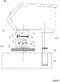
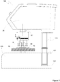
- Figure 1 and 2 show side views of a specimen mover.
- the specimen mover 100 is supported by a grinding and/or polishing machine 120 outlined schematically in broken lines.
- the grinding and/or polishing machine 120 includes a preparation surface 75.
- the preparation surface 75 is configured to receive different and not shown means for grinding, lapping and polishing the specimens 50.
- the preparation surface 75 typically is configured to operate in a not shown bowl provided to collect debris and water applied during the preparation process.
- the preparation surface 75 typically is configured to rotate.
- the rotation may be clockwise or counterclockwise.
- the preparation surface 75 rotates counter wise the rotation of the driveshaft 30 of the specimen mover 100.
- the grinding and/or polishing machine 120 may include not shown electrical means interconnecting the specimen mover 100 to the grinding and/or polishing machine 120.
- the specimen mover 100 typically resides in a slot or bore 121 provided in the base of the grinding and/or polishing machine 120.
- spacers or shims 122 may be provided between the lower end of the support post 110 supporting the specimen mover 100 and the bottom of the slot 121 of the grinding and/or polishing machine 120.
- the spacers or shims 122 facilitate height adjustment of the specimen mover 100 and are in terms of effect equivalent to the second drive mentioned in US 2014/0030967 A .
- the height adjustment of the specimen mover 100 allows for adjustment of the gap in between lower face of the specimen mover plate 15 and the upper face of the preparation surface 75.
- the gap typically is in the range of 0.5 - 5mm. depending on application.
- the thrust housing 10 is shown in a position wherein the thrust housing 10 is moved to an elevated position, i.e. out of an operative position.
- the bore 13 in the driveshaft 30 for receiving the release means 11 in an operative state is visible.
- Figure 2 shows the specimen mover in an operative state.
- the distance A is less in the operative state according to figure 2 than in the state according to figure 1 .
- the difference, i.e. the stroke of the thrust housing 10 it selves, is typically in the range of 5-50mm, 6-25mm 7-20mm, 8-15mm or about 10 mm.
- the torque generated by the preparation of the specimens is conveyed to the specimens via the specimen mover plate 15.
- the specimen mover plate 15 is rigidly mounted to, and rotated by, the driveshaft 30.
- the sectional view through a thrust housing 10 according to figure 3 shows the pawl 14 configured to interlock the thrust housing with the driveshaft 30 when the specimen mover is in the operative state according to figure 2 .
- Figure 3 further shows the thrust pads 12 connected to the thrust rods 17 via a ball joint configured for allowing firm connection, or contact, between the specimens 50 as shown in figure 2 and the thrust pads 12. Springs are in this embodiment applied to urge the thrust rods 17 towards the specimens 50.
- the thrust rods 17 may be provided with grips or handles 18 facilitating height wise adjustments of the thrust rods 17 by means of the treads 25.
- the means for applying force to the thrust rods 17 constitute, in the embodiments according the figures, springs 16.
- the springs 16 operate under pretension and the magnitude of the pretension is indicated by pins or screws 19 travelling in an aperture provided in the thrust housing 10.
- the pins or screws 19 also prevent the thrust rods 17, and any interconnecting plunger, from exiting the thrust housing 10.
- the springs 19 may be substituted by hydraulic/pneumatic actuators and the like without departing from the scope of the present invention.
- Figure 4 is perspective view of a thrust housing. As can be seen, the release means 11 may be operated by means of a simple handle 9.
- the pawl 14, as shown in figure 3 is urged against the driveshaft 30 and into the bore 13 by means of a not shown spring forming part of the release means 11.
- the operator pulls the handle 9, against the forces of the not shown spring, and the pawl 14 is withdrawn from the bore 13.
- the thrust housing 10 is now free to move upwards along the driveshaft 30 and away from the preparation surface 75.
- the thrust housing 10 and the specimen mover plate or cage 15 are arranged on driveshaft 30 protruding from drive housing 20 in a manner allowing for temporary increase of a distance (A), in-between the thrust housing 10 and the specimen mover plate or cage 15 by means of threads interconnecting the driveshaft 30 protruding from the drive housing 20 and the thrust housing 10.
- the distance (A) may in this embodiment be temporarily increased by turning the thrust housing 10 relative to the driveshaft 30 protruding from the drive housing 20.
Landscapes
- Engineering & Computer Science (AREA)
- Mechanical Engineering (AREA)
- Sampling And Sample Adjustment (AREA)
Claims (19)
- Probenbeweger (100), ausgelegt zum Rotieren einer oder mehrerer Proben (50) in Anlage an einer Herstellungsoberfläche (75), wobei der Probenbeweger (100) beinhaltet:- ein Antriebsgehäuse (20),- eine Antriebswelle (30), die aus dem Antriebsgehäuse (20) hervorsteht, und- ein Stoßgehäuse (10), das koaxial auf der Antriebswelle (30) angebracht ist, dieaus dem Antriebsgehäuse (20) hervorsteht und mindestens eine Stoßunterlage (12) beinhaltet,
dadurch gekennzeichnet, dass das Stoßgehäuse (10) mit der Antriebswelle (30), die aus dem Antriebsgehäuse (20) hervorsteht, auf eine Art und Weise verlagerbar verbunden ist, die zulässt, dass das Stoßgehäuse (10) sich entlang und relativ zur Antriebswelle (30), die aus dem Antriebsgehäuse (20) hervorsteht, bewegt. - Probenbeweger nach Anspruch 1, wobei die Herstellungsoberfläche (75) vom Probenbeweger (100) getragen wird.
- Probenbeweger nach Anspruch 1 oder 2, wobei der Probenbeweger (100) ferner eine(n) Probenbewegerplatte oder -käfig (15) beinhaltet, der koaxial zum Stoßgehäuse (10) und der Antriebswelle (30), die aus dem Antriebsgehäuse (20) hervorsteht, angebracht ist.
- Probenbeweger nach Anspruch 3, wobei das Stoßgehäuse (10) und die/der Probenbewegerplatte oder -käfig (15) auf eine Art und Weise auf der Antriebswelle (30), die aus dem Antriebsgehäuse (20) hervorsteht, angeordnet sind, die eine temporäre Zunahme eines Abstands (A) zwischen dem Stoßgehäuse (10) und der/dem Probenbewegerplatte oder -käfig (15) zulässt.
- Probenbeweger nach Anspruch 4, wobei die temporäre Zunahme des Abstands (A) zwischen dem Stoßgehäuse (10) und der/dem Probenbewegerplatte oder -käfig (15) zugelassen wird nach einer Aktivierung von Freigabemitteln (11) und nachfolgender Manipulation des Stoßgehäuses (10) entlang der Antriebswelle (30), die aus dem Antriebsgehäuse (20) hervorsteht.
- Probenbeweger nach einem oder mehreren der Ansprüche 3 bis 5, wobei die/der Probenbewegerplatte oder -käfig (15) auf der Antriebswelle (30), die aus dem Antriebsgehäuse (20) hervorsteht, auf eine Art und Weise angeordnet ist, die die/den Probenbewegerplatte oder -käfig (15) in einer festen Position gegenüber der Antriebswelle (30), die aus dem Antriebsgehäuse (20) hervorsteht, behält, unabhängig von der Position des Stoßgehäuses (10).
- Probenbeweger nach einem oder mehreren der vorhergehenden Ansprüche, wobei das Stoßgehäuse (10) Freigabemittel (11) aufnimmt, die dazu ausgelegt sind, das Stoßgehäuse (10) in und aus dem Eingriff zu bringen mit der Antriebswelle (30), die aus dem Antriebsgehäuse (20) hervorsteht, so dass das Stoßgehäuse (10) sich, wenn das Freigabemittel (11) freigegeben ist, entlang und relativ zur Antriebswelle (30), die aus dem Antriebsgehäuse (20) hervorsteht, bewegen kann.
- Probenbeweger nach Anspruch 7, wobei die Antriebswelle (30), die aus dem Antriebsgehäuse (20) hervorsteht, mit einer Bohrung (13) versehen ist und wobei das Freigabemittel (11) einen Sperrer (14) beinhaltet, der dafür ausgelegt ist, mit dem Stoßgehäuse (10) und der Antriebswelle (30), die aus dem Antriebsgehäuse (20) hervorsteht, verriegelt zu werden, dadurch, dass ein Teil des Sperrers (14) in der Bohrung (13) aufgenommen wird.
- Probenbeweger nach Anspruch 8, wobei der Sperrer (14) und die Bohrung (13) senkrecht zur Längsachse der Antriebswelle (30), die aus dem Antriebsgehäuse (20) hervorsteht, ausgerichtet sind.
- Probenbeweger nach einem oder mehreren der Ansprüche 5 bis 9, wobei das Freigabemittel (11) als Nietschloss ausgeführt ist, das dafür ausgelegt ist, mit der Bohrung (13) in Eingriff zu gehen, um das Stoßgehäuse (10) mit der Antriebswelle (30), die aus dem Antriebsgehäuse (20) hervorsteht, zu verriegeln.
- Probenbeweger nach Anspruch 5, wobei die Freigabemittel in der Antriebswelle (30), die aus dem Antriebsgehäuse (20) hervorsteht, angeordnet sind und wobei das Stoßgehäuse (10) mit einer Bohrung zur Aufnahme der in der Antriebswelle (30) angeordneten Freigabemittel versehen ist.
- Probenbeweger nach Anspruch 4, wobei das Stoßgehäuse (10) und die/der Probenbewegerplatte oder -käfig (15) auf eine Art und Weise auf der Antriebswelle (30), die aus dem Antriebsgehäuse (20) hervorsteht, angeordnet sind, die eine temporäre Zunahme eines Abstands (A) zwischen dem Stoßgehäuse (10) und der/dem Probenbewegerplatte oder -käfig (15) zulässt, durch Gewinde, die die Antriebswelle (30), die aus dem Antriebsgehäuse (20) hervorsteht, und das Stoßgehäuse (10) miteinander verbinden, und wobei der Abstand (A) temporär vergrößert werden kann, durch Drehung des Stoßgehäuses (10) relativ zu der Antriebswelle (30), die aus dem Antriebsgehäuse (20) hervorsteht.
- Probenbeweger nach einem oder mehreren der vorhergehenden Ansprüche, wobei das Stoßgehäuse (10) eine Vielzahl von Stoßunterlagen (12) beinhaltet und wobei die Vielzahl von Stoßunterlagen (12) in einer kreisförmigen Anordnung angebracht ist, mit einem geometrischen Zentrum, das koaxial zu der Antriebswelle (30), die aus dem Antriebsgehäuse (20) hervorsteht, angebracht ist.
- Probenbeweger nach einem oder mehreren der vorhergehenden Ansprüche 3 bis 13, wobei das die/der Probenbewegerplatte oder -käfig (15) eine Vielzahl von zur Aufnahme von Proben (50) ausgelegten Schlitzen beinhaltet und wobei die Vielzahl von Schlitzen in einer kreisförmigen Anordnung angebracht ist, mit einem geometrischen Zentrum, das koaxial zu der Antriebswelle (30), die aus dem Antriebsgehäuse (20) hervorsteht, angebracht ist.
- Probenbeweger nach Anspruch 13 und 14, wobei die Vielzahl von Stoßunterlagen (12) und die Vielzahl von zur Aufnahme von Proben (50) ausgelegten Schlitzen in Sätzen angeordnet ist.
- Probenbeweger nach einem oder mehreren der vorhergehenden Ansprüche, wobei das Stoßgehäuse (10) dafür ausgelegt ist, eine lineare Belastung oder Kraft auf jede der einen oder mehreren Stoßunterlagen (12) auszuüben und wobei die lineare Belastung oder Kraft von einzelnen Federn (16) stammt, die dafür ausgelegt sind, die Belastung oder Kraft auszuüben.
- Probenbeweger nach Anspruch 16, wobei die Belastung oder Kraft sich im Bereich von 2 - 40 N befindet.
- Verfahren zur Positionierung von Proben in einem Probenbeweger (100) umfassend ein Stoßgehäuse (10) und eine(n) Probenbewegerplatte oder - käfig (15), wobei das Stoßgehäuse und die/der Probenbewegerplatte oder - käfig im Wesentlichen koaxial auf einer Antriebswelle, die aus einem Antriebsgehäuse hervorsteht, angebracht sind, wobei das Verfahren die Schritte beinhaltet:- Bewegen des Stoßgehäuses entlang der Antriebswelle, die aus dem Antriebsgehäuse hervorsteht, um den Abstand (A) zwischen dem Stoßgehäuse und der/dem Probenbewegerplatte oder -käfig zu vergrößern,- Positionieren von einer oder mehreren Proben in zur Aufnahme von Proben in der/dem Probenbewegerplatte oder -käfig ausgelegten Schlitzen, und- Bewegen des Stoßgehäuses auf eine(n) Probenbewegerplatte oder -käfig zu, um Belastung oder Kraft auf die Proben auszuüben.
- Verfahren nach Anspruch 18, wobei das Verfahren ferner, vor dem Bewegen des Stoßgehäuses, um den Abstand (A) zwischen dem Stoßgehäuse und der/dem Probenbewegerplatte oder -käfig zu vergrößern, einen Schritt beinhaltet:- Freigabe von zur Verriegelung des Stoßgehäuses an der Antriebswelle, die aus dem Antriebsgehäuse hervorsteht, ausgelegten Verriegelungsmitteln.
Applications Claiming Priority (2)
| Application Number | Priority Date | Filing Date | Title |
|---|---|---|---|
| DKPA201570142 | 2015-03-13 | ||
| PCT/EP2016/055391 WO2016146557A1 (en) | 2015-03-13 | 2016-03-14 | A specimen mover and a method of placing specimens in a specimen mover |
Publications (2)
| Publication Number | Publication Date |
|---|---|
| EP3268166A1 EP3268166A1 (de) | 2018-01-17 |
| EP3268166B1 true EP3268166B1 (de) | 2019-09-11 |
Family
ID=55527575
Family Applications (1)
| Application Number | Title | Priority Date | Filing Date |
|---|---|---|---|
| EP16709783.1A Active EP3268166B1 (de) | 2015-03-13 | 2016-03-14 | Probenbeweger und verfahren zur positionierung von proben in einem probenbeweger |
Country Status (3)
| Country | Link |
|---|---|
| US (1) | US10335919B2 (de) |
| EP (1) | EP3268166B1 (de) |
| WO (1) | WO2016146557A1 (de) |
Families Citing this family (2)
| Publication number | Priority date | Publication date | Assignee | Title |
|---|---|---|---|---|
| CN111360639A (zh) * | 2020-02-25 | 2020-07-03 | 湖南云箭集团有限公司 | 一种水轮发电机推力瓦研磨装置 |
| WO2024008338A1 (en) | 2022-07-08 | 2024-01-11 | Struers ApS | A grinding and/or polishing machine and a specimen holder |
Family Cites Families (17)
| Publication number | Priority date | Publication date | Assignee | Title |
|---|---|---|---|---|
| US279001A (en) * | 1883-06-05 | Grinding and graining device | ||
| US799192A (en) * | 1904-05-02 | 1905-09-12 | A H Heisey & Company | Glass-grinding apparatus. |
| US1081715A (en) * | 1913-04-29 | 1913-12-16 | Daniel E Bigelow | Polishing-machine. |
| US3841031A (en) * | 1970-10-21 | 1974-10-15 | Monsanto Co | Process for polishing thin elements |
| DE2204581B2 (de) * | 1972-02-01 | 1977-12-08 | Wolters, Peter, 4020 Mettmann | Steuereinrichtung fuer den bearbeitungsdruck einer laepp- oder honmaschine |
| US4048763A (en) * | 1974-08-27 | 1977-09-20 | Jmj Werkzeugmaschinen Gmbh Fuer Feinbearbeitung | Method for surface-, plane-parallel-, and plain lapping |
| US4209949A (en) * | 1978-01-04 | 1980-07-01 | Staats & Staats, Inc. | Method and apparatus for high precision lapping machines |
| SE434020B (sv) * | 1981-11-10 | 1984-07-02 | Asea Ab | Slipenhet for industrirobot och automatmaskiner |
| US4534536A (en) | 1984-06-08 | 1985-08-13 | Buehler Ltd. | Apparatus for mounting samples for polishing |
| US4869779A (en) * | 1987-07-27 | 1989-09-26 | Acheson Robert E | Hydroplane polishing device and method |
| JP2660248B2 (ja) * | 1988-01-06 | 1997-10-08 | 株式会社 半導体エネルギー研究所 | 光を用いた膜形成方法 |
| US4965964A (en) * | 1989-01-17 | 1990-10-30 | John Di Camillo | Portable apparatus for processing marble tile |
| JP4273056B2 (ja) * | 2004-08-12 | 2009-06-03 | 不二越機械工業株式会社 | 研磨装置 |
| KR101358645B1 (ko) * | 2007-09-04 | 2014-02-05 | 삼성전자주식회사 | 웨이퍼 연마 캐리어 장치 및 그가 채용되는 화학적 기계적연마 설비 |
| US8574028B2 (en) | 2008-06-20 | 2013-11-05 | Illinois Tool Works Inc. | Grinder/polisher |
| KR101159918B1 (ko) | 2009-09-28 | 2012-06-25 | 현대제철 주식회사 | 시편 연마기용 시편 홀더 장치 |
| US20150228511A1 (en) * | 2014-02-10 | 2015-08-13 | GlobalFoundries, Inc. | Methods and systems for vibratory chemical mechanical planarization |
-
2016
- 2016-03-14 EP EP16709783.1A patent/EP3268166B1/de active Active
- 2016-03-14 WO PCT/EP2016/055391 patent/WO2016146557A1/en not_active Ceased
- 2016-03-14 US US15/558,069 patent/US10335919B2/en active Active
Non-Patent Citations (1)
| Title |
|---|
| None * |
Also Published As
| Publication number | Publication date |
|---|---|
| EP3268166A1 (de) | 2018-01-17 |
| US20180079049A1 (en) | 2018-03-22 |
| WO2016146557A1 (en) | 2016-09-22 |
| US10335919B2 (en) | 2019-07-02 |
Similar Documents
| Publication | Publication Date | Title |
|---|---|---|
| TW201330975A (zh) | 鑽頭之自動重磨裝置 | |
| CN113618573B (zh) | 一种陶瓷棒自动打磨装置 | |
| US10335919B2 (en) | Specimen mover and a method of placing specimens in a specimen mover | |
| JPH07104229B2 (ja) | 表面試料採取装置及び方法 | |
| CN1230276C (zh) | 手动刀具更换装置及刀具更换组件 | |
| US20050148286A1 (en) | Grinding method for vertical type of double disk surface grinding | |
| CN118664341A (zh) | 一种千斤顶组件成型加工设备 | |
| CN111421424B (zh) | 一种汽车制动鼓的无损拆隔板设备 | |
| KR101508121B1 (ko) | 캘리퍼 밀링머신 | |
| KR101484513B1 (ko) | 캘리퍼 밀링머신의 구동방법 | |
| CN118768950B (zh) | 一种铝合金板材用成批切割装置 | |
| JPH05154756A (ja) | 研磨装置 | |
| KR101867496B1 (ko) | 리테이너 링의 내구면 연마장치 | |
| KR100840732B1 (ko) | 시편 제조 장치 및 방법 | |
| CN111438622A (zh) | 一种用于金属材料抛光的夹持装置 | |
| CN117381562A (zh) | 加工设备及加工方法 | |
| CN116604420A (zh) | 一种用于石材的磨抛装置 | |
| US4359840A (en) | Automatic grinding apparatus to control uniform specimen thicknesses | |
| CN223971498U (zh) | 金相试样的夹持装置和磨制设备 | |
| CN222570159U (zh) | 一种工件圆形边缘打磨装置 | |
| US8851871B1 (en) | High-temperature high-pressure presses (HTHP) presses, systems for HTHP presses and related methods | |
| CN221248388U (zh) | 一种调节拆卸机构及打磨装置 | |
| CN119786427A (zh) | 晶圆边缘处理装置 | |
| CN110666596A (zh) | 一种用于光学元件的定位及姿态调整装置 | |
| KR20190067471A (ko) | 표면 연마 장치 |
Legal Events
| Date | Code | Title | Description |
|---|---|---|---|
| STAA | Information on the status of an ep patent application or granted ep patent |
Free format text: STATUS: THE INTERNATIONAL PUBLICATION HAS BEEN MADE |
|
| PUAI | Public reference made under article 153(3) epc to a published international application that has entered the european phase |
Free format text: ORIGINAL CODE: 0009012 |
|
| STAA | Information on the status of an ep patent application or granted ep patent |
Free format text: STATUS: REQUEST FOR EXAMINATION WAS MADE |
|
| 17P | Request for examination filed |
Effective date: 20171002 |
|
| AK | Designated contracting states |
Kind code of ref document: A1 Designated state(s): AL AT BE BG CH CY CZ DE DK EE ES FI FR GB GR HR HU IE IS IT LI LT LU LV MC MK MT NL NO PL PT RO RS SE SI SK SM TR |
|
| AX | Request for extension of the european patent |
Extension state: BA ME |
|
| DAV | Request for validation of the european patent (deleted) | ||
| DAX | Request for extension of the european patent (deleted) | ||
| GRAP | Despatch of communication of intention to grant a patent |
Free format text: ORIGINAL CODE: EPIDOSNIGR1 |
|
| STAA | Information on the status of an ep patent application or granted ep patent |
Free format text: STATUS: GRANT OF PATENT IS INTENDED |
|
| RIN1 | Information on inventor provided before grant (corrected) |
Inventor name: DRASTICH, TOMAS |
|
| INTG | Intention to grant announced |
Effective date: 20180831 |
|
| RAP1 | Party data changed (applicant data changed or rights of an application transferred) |
Owner name: STRUERS APS |
|
| GRAJ | Information related to disapproval of communication of intention to grant by the applicant or resumption of examination proceedings by the epo deleted |
Free format text: ORIGINAL CODE: EPIDOSDIGR1 |
|
| STAA | Information on the status of an ep patent application or granted ep patent |
Free format text: STATUS: REQUEST FOR EXAMINATION WAS MADE |
|
| INTC | Intention to grant announced (deleted) | ||
| GRAP | Despatch of communication of intention to grant a patent |
Free format text: ORIGINAL CODE: EPIDOSNIGR1 |
|
| STAA | Information on the status of an ep patent application or granted ep patent |
Free format text: STATUS: GRANT OF PATENT IS INTENDED |
|
| INTG | Intention to grant announced |
Effective date: 20190429 |
|
| GRAS | Grant fee paid |
Free format text: ORIGINAL CODE: EPIDOSNIGR3 |
|
| GRAA | (expected) grant |
Free format text: ORIGINAL CODE: 0009210 |
|
| STAA | Information on the status of an ep patent application or granted ep patent |
Free format text: STATUS: THE PATENT HAS BEEN GRANTED |
|
| AK | Designated contracting states |
Kind code of ref document: B1 Designated state(s): AL AT BE BG CH CY CZ DE DK EE ES FI FR GB GR HR HU IE IS IT LI LT LU LV MC MK MT NL NO PL PT RO RS SE SI SK SM TR |
|
| REG | Reference to a national code |
Ref country code: GB Ref legal event code: FG4D |
|
| REG | Reference to a national code |
Ref country code: CH Ref legal event code: EP |
|
| REG | Reference to a national code |
Ref country code: AT Ref legal event code: REF Ref document number: 1177827 Country of ref document: AT Kind code of ref document: T Effective date: 20190915 |
|
| REG | Reference to a national code |
Ref country code: DE Ref legal event code: R096 Ref document number: 602016020348 Country of ref document: DE Ref country code: IE Ref legal event code: FG4D |
|
| REG | Reference to a national code |
Ref country code: NL Ref legal event code: MP Effective date: 20190911 |
|
| REG | Reference to a national code |
Ref country code: LT Ref legal event code: MG4D |
|
| PG25 | Lapsed in a contracting state [announced via postgrant information from national office to epo] |
Ref country code: NO Free format text: LAPSE BECAUSE OF FAILURE TO SUBMIT A TRANSLATION OF THE DESCRIPTION OR TO PAY THE FEE WITHIN THE PRESCRIBED TIME-LIMIT Effective date: 20191211 Ref country code: BG Free format text: LAPSE BECAUSE OF FAILURE TO SUBMIT A TRANSLATION OF THE DESCRIPTION OR TO PAY THE FEE WITHIN THE PRESCRIBED TIME-LIMIT Effective date: 20191211 Ref country code: FI Free format text: LAPSE BECAUSE OF FAILURE TO SUBMIT A TRANSLATION OF THE DESCRIPTION OR TO PAY THE FEE WITHIN THE PRESCRIBED TIME-LIMIT Effective date: 20190911 Ref country code: LT Free format text: LAPSE BECAUSE OF FAILURE TO SUBMIT A TRANSLATION OF THE DESCRIPTION OR TO PAY THE FEE WITHIN THE PRESCRIBED TIME-LIMIT Effective date: 20190911 Ref country code: HR Free format text: LAPSE BECAUSE OF FAILURE TO SUBMIT A TRANSLATION OF THE DESCRIPTION OR TO PAY THE FEE WITHIN THE PRESCRIBED TIME-LIMIT Effective date: 20190911 Ref country code: SE Free format text: LAPSE BECAUSE OF FAILURE TO SUBMIT A TRANSLATION OF THE DESCRIPTION OR TO PAY THE FEE WITHIN THE PRESCRIBED TIME-LIMIT Effective date: 20190911 |
|
| PG25 | Lapsed in a contracting state [announced via postgrant information from national office to epo] |
Ref country code: AL Free format text: LAPSE BECAUSE OF FAILURE TO SUBMIT A TRANSLATION OF THE DESCRIPTION OR TO PAY THE FEE WITHIN THE PRESCRIBED TIME-LIMIT Effective date: 20190911 Ref country code: LV Free format text: LAPSE BECAUSE OF FAILURE TO SUBMIT A TRANSLATION OF THE DESCRIPTION OR TO PAY THE FEE WITHIN THE PRESCRIBED TIME-LIMIT Effective date: 20190911 Ref country code: GR Free format text: LAPSE BECAUSE OF FAILURE TO SUBMIT A TRANSLATION OF THE DESCRIPTION OR TO PAY THE FEE WITHIN THE PRESCRIBED TIME-LIMIT Effective date: 20191212 Ref country code: RS Free format text: LAPSE BECAUSE OF FAILURE TO SUBMIT A TRANSLATION OF THE DESCRIPTION OR TO PAY THE FEE WITHIN THE PRESCRIBED TIME-LIMIT Effective date: 20190911 Ref country code: ES Free format text: LAPSE BECAUSE OF FAILURE TO SUBMIT A TRANSLATION OF THE DESCRIPTION OR TO PAY THE FEE WITHIN THE PRESCRIBED TIME-LIMIT Effective date: 20190911 |
|
| REG | Reference to a national code |
Ref country code: AT Ref legal event code: MK05 Ref document number: 1177827 Country of ref document: AT Kind code of ref document: T Effective date: 20190911 |
|
| PG25 | Lapsed in a contracting state [announced via postgrant information from national office to epo] |
Ref country code: PT Free format text: LAPSE BECAUSE OF FAILURE TO SUBMIT A TRANSLATION OF THE DESCRIPTION OR TO PAY THE FEE WITHIN THE PRESCRIBED TIME-LIMIT Effective date: 20200113 Ref country code: IT Free format text: LAPSE BECAUSE OF FAILURE TO SUBMIT A TRANSLATION OF THE DESCRIPTION OR TO PAY THE FEE WITHIN THE PRESCRIBED TIME-LIMIT Effective date: 20190911 Ref country code: PL Free format text: LAPSE BECAUSE OF FAILURE TO SUBMIT A TRANSLATION OF THE DESCRIPTION OR TO PAY THE FEE WITHIN THE PRESCRIBED TIME-LIMIT Effective date: 20190911 Ref country code: EE Free format text: LAPSE BECAUSE OF FAILURE TO SUBMIT A TRANSLATION OF THE DESCRIPTION OR TO PAY THE FEE WITHIN THE PRESCRIBED TIME-LIMIT Effective date: 20190911 Ref country code: AT Free format text: LAPSE BECAUSE OF FAILURE TO SUBMIT A TRANSLATION OF THE DESCRIPTION OR TO PAY THE FEE WITHIN THE PRESCRIBED TIME-LIMIT Effective date: 20190911 Ref country code: NL Free format text: LAPSE BECAUSE OF FAILURE TO SUBMIT A TRANSLATION OF THE DESCRIPTION OR TO PAY THE FEE WITHIN THE PRESCRIBED TIME-LIMIT Effective date: 20190911 Ref country code: RO Free format text: LAPSE BECAUSE OF FAILURE TO SUBMIT A TRANSLATION OF THE DESCRIPTION OR TO PAY THE FEE WITHIN THE PRESCRIBED TIME-LIMIT Effective date: 20190911 |
|
| PG25 | Lapsed in a contracting state [announced via postgrant information from national office to epo] |
Ref country code: IS Free format text: LAPSE BECAUSE OF FAILURE TO SUBMIT A TRANSLATION OF THE DESCRIPTION OR TO PAY THE FEE WITHIN THE PRESCRIBED TIME-LIMIT Effective date: 20200224 Ref country code: CZ Free format text: LAPSE BECAUSE OF FAILURE TO SUBMIT A TRANSLATION OF THE DESCRIPTION OR TO PAY THE FEE WITHIN THE PRESCRIBED TIME-LIMIT Effective date: 20190911 Ref country code: SM Free format text: LAPSE BECAUSE OF FAILURE TO SUBMIT A TRANSLATION OF THE DESCRIPTION OR TO PAY THE FEE WITHIN THE PRESCRIBED TIME-LIMIT Effective date: 20190911 Ref country code: SK Free format text: LAPSE BECAUSE OF FAILURE TO SUBMIT A TRANSLATION OF THE DESCRIPTION OR TO PAY THE FEE WITHIN THE PRESCRIBED TIME-LIMIT Effective date: 20190911 |
|
| REG | Reference to a national code |
Ref country code: DE Ref legal event code: R097 Ref document number: 602016020348 Country of ref document: DE |
|
| PLBE | No opposition filed within time limit |
Free format text: ORIGINAL CODE: 0009261 |
|
| STAA | Information on the status of an ep patent application or granted ep patent |
Free format text: STATUS: NO OPPOSITION FILED WITHIN TIME LIMIT |
|
| PG2D | Information on lapse in contracting state deleted |
Ref country code: IS |
|
| PG25 | Lapsed in a contracting state [announced via postgrant information from national office to epo] |
Ref country code: DK Free format text: LAPSE BECAUSE OF FAILURE TO SUBMIT A TRANSLATION OF THE DESCRIPTION OR TO PAY THE FEE WITHIN THE PRESCRIBED TIME-LIMIT Effective date: 20190911 Ref country code: IS Free format text: LAPSE BECAUSE OF FAILURE TO SUBMIT A TRANSLATION OF THE DESCRIPTION OR TO PAY THE FEE WITHIN THE PRESCRIBED TIME-LIMIT Effective date: 20200112 |
|
| 26N | No opposition filed |
Effective date: 20200615 |
|
| PG25 | Lapsed in a contracting state [announced via postgrant information from national office to epo] |
Ref country code: SI Free format text: LAPSE BECAUSE OF FAILURE TO SUBMIT A TRANSLATION OF THE DESCRIPTION OR TO PAY THE FEE WITHIN THE PRESCRIBED TIME-LIMIT Effective date: 20190911 |
|
| PG25 | Lapsed in a contracting state [announced via postgrant information from national office to epo] |
Ref country code: MC Free format text: LAPSE BECAUSE OF FAILURE TO SUBMIT A TRANSLATION OF THE DESCRIPTION OR TO PAY THE FEE WITHIN THE PRESCRIBED TIME-LIMIT Effective date: 20190911 |
|
| REG | Reference to a national code |
Ref country code: CH Ref legal event code: PL |
|
| REG | Reference to a national code |
Ref country code: BE Ref legal event code: MM Effective date: 20200331 |
|
| PG25 | Lapsed in a contracting state [announced via postgrant information from national office to epo] |
Ref country code: LU Free format text: LAPSE BECAUSE OF NON-PAYMENT OF DUE FEES Effective date: 20200314 |
|
| PG25 | Lapsed in a contracting state [announced via postgrant information from national office to epo] |
Ref country code: LI Free format text: LAPSE BECAUSE OF NON-PAYMENT OF DUE FEES Effective date: 20200331 Ref country code: IE Free format text: LAPSE BECAUSE OF NON-PAYMENT OF DUE FEES Effective date: 20200314 Ref country code: CH Free format text: LAPSE BECAUSE OF NON-PAYMENT OF DUE FEES Effective date: 20200331 |
|
| PG25 | Lapsed in a contracting state [announced via postgrant information from national office to epo] |
Ref country code: BE Free format text: LAPSE BECAUSE OF NON-PAYMENT OF DUE FEES Effective date: 20200331 |
|
| GBPC | Gb: european patent ceased through non-payment of renewal fee |
Effective date: 20200314 |
|
| PG25 | Lapsed in a contracting state [announced via postgrant information from national office to epo] |
Ref country code: GB Free format text: LAPSE BECAUSE OF NON-PAYMENT OF DUE FEES Effective date: 20200314 |
|
| PG25 | Lapsed in a contracting state [announced via postgrant information from national office to epo] |
Ref country code: TR Free format text: LAPSE BECAUSE OF FAILURE TO SUBMIT A TRANSLATION OF THE DESCRIPTION OR TO PAY THE FEE WITHIN THE PRESCRIBED TIME-LIMIT Effective date: 20190911 Ref country code: MT Free format text: LAPSE BECAUSE OF FAILURE TO SUBMIT A TRANSLATION OF THE DESCRIPTION OR TO PAY THE FEE WITHIN THE PRESCRIBED TIME-LIMIT Effective date: 20190911 Ref country code: CY Free format text: LAPSE BECAUSE OF FAILURE TO SUBMIT A TRANSLATION OF THE DESCRIPTION OR TO PAY THE FEE WITHIN THE PRESCRIBED TIME-LIMIT Effective date: 20190911 |
|
| PG25 | Lapsed in a contracting state [announced via postgrant information from national office to epo] |
Ref country code: MK Free format text: LAPSE BECAUSE OF FAILURE TO SUBMIT A TRANSLATION OF THE DESCRIPTION OR TO PAY THE FEE WITHIN THE PRESCRIBED TIME-LIMIT Effective date: 20190911 |
|
| P01 | Opt-out of the competence of the unified patent court (upc) registered |
Effective date: 20230508 |
|
| PGFP | Annual fee paid to national office [announced via postgrant information from national office to epo] |
Ref country code: DE Payment date: 20260320 Year of fee payment: 11 |
|
| PGFP | Annual fee paid to national office [announced via postgrant information from national office to epo] |
Ref country code: FR Payment date: 20260324 Year of fee payment: 11 |