US8851871B1 - High-temperature high-pressure presses (HTHP) presses, systems for HTHP presses and related methods - Google Patents
High-temperature high-pressure presses (HTHP) presses, systems for HTHP presses and related methods Download PDFInfo
- Publication number
- US8851871B1 US8851871B1 US13/738,647 US201313738647A US8851871B1 US 8851871 B1 US8851871 B1 US 8851871B1 US 201313738647 A US201313738647 A US 201313738647A US 8851871 B1 US8851871 B1 US 8851871B1
- Authority
- US
- United States
- Prior art keywords
- press
- hthp
- reaction cell
- assembly
- guide
- Prior art date
- Legal status (The legal status is an assumption and is not a legal conclusion. Google has not performed a legal analysis and makes no representation as to the accuracy of the status listed.)
- Active
Links
Images


Classifications
-
- B—PERFORMING OPERATIONS; TRANSPORTING
- B29—WORKING OF PLASTICS; WORKING OF SUBSTANCES IN A PLASTIC STATE IN GENERAL
- B29C—SHAPING OR JOINING OF PLASTICS; SHAPING OF MATERIAL IN A PLASTIC STATE, NOT OTHERWISE PROVIDED FOR; AFTER-TREATMENT OF THE SHAPED PRODUCTS, e.g. REPAIRING
- B29C43/00—Compression moulding, i.e. applying external pressure to flow the moulding material; Apparatus therefor
- B29C43/02—Compression moulding, i.e. applying external pressure to flow the moulding material; Apparatus therefor of articles of definite length, i.e. discrete articles
-
- B—PERFORMING OPERATIONS; TRANSPORTING
- B01—PHYSICAL OR CHEMICAL PROCESSES OR APPARATUS IN GENERAL
- B01J—CHEMICAL OR PHYSICAL PROCESSES, e.g. CATALYSIS OR COLLOID CHEMISTRY; THEIR RELEVANT APPARATUS
- B01J3/00—Processes of utilising sub-atmospheric or super-atmospheric pressure to effect chemical or physical change of matter; Apparatus therefor
- B01J3/06—Processes using ultra-high pressure, e.g. for the formation of diamonds; Apparatus therefor, e.g. moulds or dies
-
- B—PERFORMING OPERATIONS; TRANSPORTING
- B30—PRESSES
- B30B—PRESSES IN GENERAL
- B30B11/00—Presses specially adapted for forming shaped articles from material in particulate or plastic state, e.g. briquetting presses, tabletting presses
- B30B11/004—Presses specially adapted for forming shaped articles from material in particulate or plastic state, e.g. briquetting presses, tabletting presses involving the use of very high pressures
-
- B—PERFORMING OPERATIONS; TRANSPORTING
- B30—PRESSES
- B30B—PRESSES IN GENERAL
- B30B15/00—Details of, or accessories for, presses; Auxiliary measures in connection with pressing
- B30B15/02—Dies; Inserts therefor; Mounting thereof; Moulds
- B30B15/028—Loading or unloading of dies, platens or press rams
-
- B—PERFORMING OPERATIONS; TRANSPORTING
- B30—PRESSES
- B30B—PRESSES IN GENERAL
- B30B15/00—Details of, or accessories for, presses; Auxiliary measures in connection with pressing
- B30B15/30—Feeding material to presses
-
- B—PERFORMING OPERATIONS; TRANSPORTING
- B30—PRESSES
- B30B—PRESSES IN GENERAL
- B30B15/00—Details of, or accessories for, presses; Auxiliary measures in connection with pressing
- B30B15/30—Feeding material to presses
- B30B15/302—Feeding material in particulate or plastic state to moulding presses
- B30B15/304—Feeding material in particulate or plastic state to moulding presses by using feed frames or shoes with relative movement with regard to the mould or moulds
-
- B—PERFORMING OPERATIONS; TRANSPORTING
- B01—PHYSICAL OR CHEMICAL PROCESSES OR APPARATUS IN GENERAL
- B01J—CHEMICAL OR PHYSICAL PROCESSES, e.g. CATALYSIS OR COLLOID CHEMISTRY; THEIR RELEVANT APPARATUS
- B01J3/00—Processes of utilising sub-atmospheric or super-atmospheric pressure to effect chemical or physical change of matter; Apparatus therefor
- B01J3/06—Processes using ultra-high pressure, e.g. for the formation of diamonds; Apparatus therefor, e.g. moulds or dies
- B01J3/065—Presses for the formation of diamonds or boronitrides
- B01J3/067—Presses using a plurality of pressing members working in different directions
Definitions
- the present invention relates to high-temperature, high-pressure presses including systems for loading cubes to be pressed thereby and related methods.
- High pressure presses have been used for decades in the manufacture of synthetic diamond. Such presses are capable of exerting a high pressure and high temperature on a volume of carbonaceous material to create conditions for sintering polycrystalline diamond.
- Known designs for high pressure presses include, but are not limited to, the belt press, the tetrahedral press, and the cubic press.
- FIG. 1 shows a design for a conventional cubic press 10 known in the art.
- the design generally includes six press bases 12 , with each press base 12 facing towards a common central point 14 .
- the press bases 12 may include a body that exhibits a generally conical shape, with an outer surface 16 and an inner surface 18 .
- the inner surface 18 houses a piston 20 , which is capable of being displaced towards the central point 14 .
- Tie bars 28 may extend between and be coupled to individual press bases 12 to form a structural framework that supports the press bases 12 during operation of the press 10 .
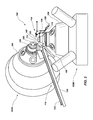
- FIG. 2 shows a close-up view of various components surrounding the central point 14 of the cubic press 10 .
- Guide pins 22 help to keep the pistons 20 aligned as they move in and out of the press bases 12 .
- An anvil 24 is coupled to each of pistons 20 and may include an engagement surface 26 aligned perpendicularly to the axis of motion of the piston 20 .
- the engagement surfaces 26 of the anvils 24 collectively converge upon a defined cube-shaped volume disposed about the central point 14 . This volume may be occupied with a cube-shaped reaction cell containing materials that are to be converted to synthetic diamond.
- the square anvil surfaces 26 apply pressure and heat to the reaction cell to create the necessary conditions within the reaction cell for forming synthetic diamond.
- the reaction cell is conventionally placed on an anvil 24 (i.e., on the lowermost anvil of the press) by an operator of the press.
- the operator uses a spacer or a template structure configured to help place the reaction cell at a specified position on the supporting anvil and in a predetermined orientation with respect to one or more of the anvils 24 .
- Positioning of the reaction cell by hand even when using precision templates or spacers, often results in inconsistencies in the placement of the reaction cell relative to each of the anvils 24 .
- the pistons may have variation in their positioning when they return to a “rest” state from one cycle to another, thereby making the method of using a template inaccurate.
- human error inevitably impacts the placement of a reaction cell regardless of how careful an operator is.
- Improper placement of the reaction cell can affect the operations of the press and, importantly, affect the quality of the synthetic diamond material being produced. Furthermore, in order to properly position the reaction cell, an operator has to position their body between adjacent press bases and reach in towards the anvils. This can be difficult from an ergonomic standpoint and can also be a safety hazard in certain situations. Additionally, hand placement and alignment of the reaction cell is not a particularly fast process and may be a limiting factor in the production efficiency of synthetic diamond or other superabrasive compacts.
- an automated loading system for a HTHP press includes a first assembly comprising a support member, a trolley displaceable relative to the support member and a positioning mechanism coupled with the trolley configured to carry a reaction cell.
- the system further includes a second assembly comprising a bracket, a body portion displaceable relative to the bracket, an alignment guide and a first positioning guide configured to cooperate with the positioning mechanism of the first assembly to position a reaction cell carried by the positioning mechanism at a desired location relative to a defined component of a HTHP press.
- the first assembly may further include a guide member coupled to the support member, the trolley being slidably coupled with the guide member.
- the positioning mechanism may include a base member and a second positioning guide movably coupled with the base member.
- the first positioning guide may include a pair of guide arms configured to engage two distinct sides of a cubic reaction cell while the second positioning guide may also include a pair of guide arms configured to engage two other distinct sides of a cubic reaction cell.
- a first actuator may be configured to displace the trolley along the guide member and a second actuator may be configured to displace the second positioning guide relative to the base member.
- the second assembly may comprise a pair of arms pivotally coupled between the bracket and the body portion to form a multiple bar linkage.
- a third actuator or a dyad is configured to displace the pair of arms between at least two different positions.
- the loading system may also include a clearing mechanism associated with the second assembly.
- the clearing mechanism includes a sweeper and another actuator configured to displace the sweeper between at least two positions relative to the body portion of the second assembly.
- the loading system may include a coupling assembly configured to couple the support member of the first assembly to a component of a HTHP press such as a press base or a piston.
- the coupling assembly includes a first body portion coupled with the support member and a second body portion configured to be coupled with a component of a HTHP press such as a press base or a piston.
- One of the first body portion and the second body portion may include a latching member and the other of the first body portion and the second body portion may include a pin to be engaged by the latching member.
- the first body portion may include a first engagement structure and the second body portion may include a second engagement structure sized and configured to mate with the first engagement structure.
- a high-temperature, high-pressure press includes a first press base having a piston and an anvil coupled with the piston and an automated loading system.
- the automated loading system includes a first assembly and a second assembly associated with the first press base.
- the first assembly includes a support member, a trolley displaceable relative to the support member and a positioning mechanism coupled with the trolley configured to carry a reaction cell to the anvil of the first press base.
- the second assembly includes a bracket coupled with the first press base, a body portion displaceable relative to the bracket, an alignment guide configured to engage a surface of the anvil and a first positioning guide configured to cooperate with the positioning mechanism of the first assembly to position a reaction cell at a desired location on the anvil.
- the press may also include any of the various features or components described herein with respect to the loading system.
- the press may be configured as a cubic press having six press bases.
- a method of operating a high-pressure, high-temperature press includes positioning a reaction cell on a first assembly of a loading system.
- the reaction cell is carried on a trolley of the first assembly to a location adjacent an anvil of a press base of the HTHP press.
- a first guide member associated with a second assembly is positioned at a desired location relative to the anvil and the reaction cell is placed on the anvil in a desired position and orientation by engaging the reaction cell with the first guide member and with a second guide member associated with the first assembly.
- the first guide member and the second guide member are retracted while leaving the reaction cell on the anvil and the reaction cell is subject to a HTHP process.
- the method includes actuating a clearing mechanism associated with the second assembly to remove the reaction cell subsequent the HTHP process. In another embodiment, the method includes actuating a clearing mechanism associated with the second assembly to sweep a surface of the anvil prior to placing the reaction cell on the anvil.
- FIG. 1 is a side view of a cubic press
- FIG. 2 is a detailed view of certain components of the press shown in FIG. 1 ;
- FIG. 3 shows two press bases of a cubic press and a loading system according to an embodiment of the invention
- FIG. 4 is a perspective view of certain components of the loading system shown in FIG. 4 ;
- FIG. 5 is another perspective view of the components shown in FIG. 4 ;
- FIG. 6A shows further details of components from the loading system shown in FIGS. 4 and 5 ;
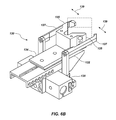
- FIG. 6B shows another embodiment of the components shown in FIG. 6A ;
- FIG. 6C shows a further embodiment of the components shown in FIG. 6A ;
- FIG. 7 is a first perspective view of various components used in coupling portions of the loading system with a press base according to an embodiment of the invention.
- FIG. 8 is another perspective view of the components shown in FIG. 7
- FIG. 9 is a perspective view of additional components of the loading system shown in FIG. 3 ;
- FIG. 10 is another perspective view of the components shown in FIG. 9 ;
- FIG. 11 is a further perspective view of the components shown in FIG. 9 ;
- FIG. 12 is a front view of another component associated with the loading system.
- FIGS. 13A-13I show side views of a press base along with various components of the loading system shown in FIG. 3 while in various states of operation.
- FIG. 3 a loading system 100 for a press is shown and described. While the loading system 100 may be used with a variety of press types, the present description is made with reference to a cubic press. For purposes of clarity and convenience, the entirety of the press is not shown in FIG. 3 . Rather, a first press base 102 A and a second press base 102 B are shown for context while enabling a better view of the loading system 100 and its various components.
- Each press base 102 A and 102 B may include, for example, a body portion 104 which houses a piston 106 having an anvil 108 coupled therewith.
- the pistons 106 may be cooperatively actuated so that their associated anvils 108 are displaced and converge upon a central point, at which a reaction cell may be positioned.
- the pistons 106 apply pressure to a reaction cell through their associated anvils 108 as part of a high-temperature, high-pressure (HTHP) process for forming polycrystalline diamond or another sintered material.
- HTHP high-temperature, high-pressure
- six different press bases would be arranged such that their respective anvils converged to apply pressure on a reaction cell with pressure being applied substantially equally on each side of the reaction cell.
- the loading system 100 includes a first assembly 110 configured to carry and place a reaction cell 112 on the face of an anvil (i.e., on the anvil 108 of press base 102 B) and a second assembly 114 that helps to correctly position the reaction cell on the anvil 108 .
- the second assembly 114 also ensures that the surface of the anvil is clear of debris or obstacles prior to a reaction cell 112 being positioned thereon, and further assists in removing the reaction cell 112 after it has been subjected to an HTHP process by the press.
- the first assembly 110 may include a beam 120 that supports a rail or guide 122 (in this embodiment, a linear guide).
- a trolley 124 may be coupled with the linear guide 122 , such as by way of a linear bearing, enabling the trolley 124 to be slidably displaced along the linear guide 122 from one end to the other.
- a variety of mechanisms or actuators may be used to displace the trolley 124 along the linear guide 122 .
- a pneumatic or hydraulic actuator may be used to displace the trolley 124 .
- the trolley 124 may be driven by a belt or a chain coupled with an appropriate drive motor.
- the linear guide 122 and the trolley 124 may be configured to act as a linear drive using electromagnets.
- the trolley 124 may be displaced by a screw drive.
- an electric motor may be coupled to the trolley 124 and configured to engage the linear guide 122 (e.g., by rack and pinion gearing) to position the trolley 124 along the linear guide 122 .
- Attached to the trolley 124 is a positioning mechanism 130 that includes a base member 132 , a positioning guide member 134 and an actuator 136 configured to displace the positioning guide member 134 relative to the base member 132 .
- the positioning guide member 134 may include a pair of forked arms 135 configured to engage two adjacent sides of a cubic reaction cell while the reaction cell 112 rests upon a surface of the base member 132 .
- the positioning guide member 134 is configured to assist in the placement of the reaction cell on a surface of the anvil 108 .
- the relative displacement of the positioning guide member 134 with respect to the base member 132 may be accomplished by a variety of mechanisms including bearing elements (e.g., ball bearings or roller bearings), an interface surface with reduced friction (e.g., Teflon) positioned between the two components or other dry contact materials as will be appreciated by those of ordinary skill in the art.
- bearing elements e.g., ball bearings or roller bearings
- an interface surface with reduced friction e.g., Teflon
- FIG. 6B another embodiment is shown of the positioning mechanism 130 that includes a pair of laterally positionable grasping arms 137 adjacent the forked arms 135 .
- the grasping arms 137 may be coupled with an actuator 138 which is configured to displace the grasping arms 137 laterally away from one another and towards one another as indicated generally by directional arrows 139 .
- the grasping arms 137 may be used to affirmatively grasp or hold a reaction cell (shown in dashed lines for reference in FIG. 6B ) during transport and placement of the reaction cell.
- such grasping arms 137 may be used as a pick-and-place mechanism to acquire the reaction cell from a stock or supply of reaction cells, carry the reaction cell to the anvil of a press base, and subsequently retrieve and dispose of the reaction cell following an HTHP process.
- the grasping arms 137 and other components e.g., the positioning guide member 134 and forked arms 135 ) may be adjustable relative to one another to accommodate various sizes of reaction cells.
- the positioning mechanism 130 which includes one or more adjustable alignment structures, in this case a pair of spherical point set screws 160 with one being positioned along the inside face of each forked arm 135 .
- the set screws 160 enable fine adjustment of the position of the reaction cell 112 relative to the positioning guide member 134 and guide arms 135 subsequent attachment of the first assembly 110 to the press.
- one set screw 160 may be adjusted “out” from the surface of its associated arm 135 (e.g., by way of a threaded coupling with the arm 135 ) while the other set screw 160 being adjusted “in” to the surface its associated arm 135 .
- both set screws 160 may be adjusted “out” or “in” a similar distance to enable the position of the reaction cell 112 to be adjusted either away from or towards both arms 135 an equal distance (i.e., towards or away from the “V” formed by the forked arms 135 and as indicated by directional arrow 164 ).
- the spherical end surfaces 166 of the set screws enable a reaction cell 112 to easily slide relative to the forked arms 135 and become seated in a desired position and orientation relative to the forked arms 135 during loading and handling of the reaction cell 112 .
- An adjustable abutment plate 168 may also be positioned in association with the forked arms 135 to act as a third contact point in positioning and orienting the reaction cell 112 while also providing additional fine adjustment capabilities to the positioning mechanism 130 (e.g., in the direction indicated by directional arrow 166 ). It is noted that, while various embodiments of the positioning mechanism 130 have been shown in FIGS. 6A-6C , such embodiments are not mutually exclusive of one another but, rather, the features shown in FIGS. 6A-6C may be combined without limitation.
- the first assembly 110 may include a quick-connect coupling assembly 140 for coupling with an associated press base 102 B.
- the coupling assembly 140 may include a first body member 142 coupled with the beam 120 , for example, by way of mechanical fasteners, welding or other appropriate fastening or joining techniques.
- the beam 120 and body portion may be formed as an integral component.
- a second body member 144 is coupled with a flange 146 or other component of the press base 102 B (e.g., a flange associated with the piston assembly of the press base 102 B).
- the second body member 144 may likewise be coupled with the flange 146 or other component, for example, by way of mechanical fasteners, welding, other appropriate fastening or joining techniques or it may be integrally formed with such a component.
- One or more engagement pins 148 may be associated with the first body member 142 and configured to engage associated holes, apertures or other keyed geometric features (referred to generally herein as apertures 150 ) to ensure a desired orientation and alignment of the first assembly 110 of the loading system 100 with a press base 102 B. Similar features may be used in coupling the first body member 142 with the beam 120 and/or the second body member 144 with the flange 146 or other component if desired.
- a locking mechanism 152 may also be associated with the first body member 142 .
- a lever 154 or other actuating mechanism may be associated with one or more latching members 156 such that, when assembled with the engagement pins 148 positioned within their associated apertures 150 , the lever 154 may be actuated causing the latching members 156 to engage an associated pin 158 or other structure and lock the first body member 142 in position relative to the second body member 144 .
- Such an assembly acts as a quick connect/disconnect system and enables the loading system 100 , or portions thereof, to be easily coupled to, and removed from, a press base for replacement, repair or routine maintenance. Additionally, such an assembly provides the ability to easily adapt the present loading system to an existing press without the need to substantially modify a press base or other component of the press.
- the loading system 100 may be directly coupled to a piston 106 of a press base and be fully supported by such a connection (e.g., the first assembly 110 being cantilevered therefrom).
- a connection e.g., the first assembly 110 being cantilevered therefrom.
- other coupling mechanisms including other quick connect/disconnect mechanisms, may be used for coupling the loading system, or any specific assemblies or components thereof, with a press.
- the second assembly 114 may include a mounting flange 170 that may be coupled with press base 102 B.
- the mounting flange 170 may be coupled with, or take the place of, an existing flange associated with the piston 106 of the press base 102 B.
- a pair of arms 172 is pivotally coupled to the mounting flange by way of an associated bracket.
- a body portion 176 is pivotally coupled to each of the arms 172 such that the body portion 176 , the pair of arms 172 and the bracket 174 work together as a set of mechanical linkages such that the body portion 176 may be displaced along a curved path relative to the bracket 174 and mounting flange 170 .
- FIGS. 9 and 10 where, in FIG. 9 , the arms 172 and body portion 176 have been rotated back and generally away from the mounting flange 170 , while in FIG. 10 the arms 172 have been rotated up and towards the mounting flange 170 . In both positions (i.e., the positions shown in FIGS.
- the body portion 176 while being laterally displaced and while also changing its elevational position, maintains a common orientation relative to the mounting flange 170 .
- an actuator 178 or a driver dyad may be coupled between one of the arms 172 and a bracket 180 or other structural member.
- the actuator 178 which may include a pneumatic or hydraulic cylinder (or any of a variety of components such as described above), may be used to position the body portion 176 and associated components relative to an anvil 108 of the press base 102 B as will be described in further detail below.
- a guide member 182 is coupled with the body portion and, in one embodiment, may include a pair of spaced apart arms 184 .
- the guide member 182 may be used to help ensure proper alignment and positioning of the various components of the second assembly 114 relative to the anvil 108 of a press base 102 B during operation of the loading system 100 .
- the spaced apart arms 184 may be configured to engage the peripheral sides of an anvil when the body portion 176 is rotated into a desired position (e.g., when the body portion 176 is rotated into the position shown in FIGS. 3 , 10 and 11 .
- a reaction cell positioning guide 186 may also be coupled to the body portion 176 , such as by way of a bracket 188 .
- the positioning guide 186 may be used to help position a reaction cell on an anvil at a desired location and in a desired orientation as will be discussed in further detail below.
- the positioning guide 186 may include a pair of forked or angled arms 189 configured to engage adjacent sides of a generally cubic reaction cell.
- components of the first assembly 110 and the second assembly 114 may be adjustable (e.g., laterally, elevationally, angularly, etc.), and may even include additional components, for purposes of alignment and/or to enable the handling and accurate placement of a variety of different sized reaction cells.
- adjustment may be accomplished through control of the first and second assemblies 110 and 114 by providing a reference point relative to the position of the anvil and then tracking or sensing the position of certain components of the first and second assemblies (e.g., through the use of appropriate sensors or encoders) and then comparing them to an intended position of such components based on a desired placement of a reaction cell (in terms of location and orientation) relative to the reference point and in light of the size and shape of the reaction cell being positioned.
- the bracket 188 and angled arms 189 may be adjustable relative to the body portion 176 in a direction towards and away from the anvil.
- relative adjustment of up to 0.5 inches or greater may be used to accommodate different sized reaction cells. Such adjustment may be done by hand, or may be done using additional actuators.
- a ball screw actuator may be used to automatically adjust the position of the bracket 188 and arms 189 relative to the body portion 176 based on input to the system from an operator or from a computerized controller.
- a clearing mechanism 190 may also be coupled with or otherwise associated with the body portion 176 .
- the clearing mechanism 190 may include an actuator 192 such as a pneumatic or hydraulic cylinder (or other appropriate mechanism such as set forth above) coupled with a sweeper 194 .
- the sweeper 194 may be configured, for example, as a brush or as a squeegee.
- the clearing mechanism 190 may be used to remove reaction cells from an anvil as well as to ensure that the surface of the anvil is clear of debris or obstructions prior to placing a reaction cell thereon. As shown in FIGS.
- a discharge chute 196 may be coupled with the press (e.g., a press base 102 B or a piston 106 of a press base) and be configured and oriented to catch any reaction cells 112 that are cleared from the anvil 108 following an HTHP process.
- the chute 196 may be configured to extend at least partially around the periphery of the press component to which it is mounted. In the embodiment shown, when the clearing mechanism 190 clears a reaction cell 112 from the anvil, it may be discharged in a direction generally towards the first assembly 110 and fall to either side of the rail or linear guide member (not shown in FIG. 12 ) into the discharge chute 196 .
- the reaction cell 112 may slide down the discharge chute 196 and exit into a collection bin, onto a conveyor belt, or into some other collection mechanism.
- the clearing mechanism 190 may be configured to generally direct the reaction cell 112 to one side or the other of the first assembly 110 and into the discharge chute 196 .
- the sweeper 194 may be displaced in a direction that, while generally towards the first assembly 110 , is somewhat to the right or the left of the first assembly 110 so that the reaction cell 112 avoids hitting or landing on the first assembly 110 .
- the sweeper 194 may be oriented at an angle relative to its direction of displacement, again to bias the reaction cell to one side or the other of the first assembly 110 and enable it to fall into the discharge chute 196 .
- FIGS. 13A-13J operation of the loading system 100 is described in accordance with one example embodiment. It is noted that FIGS. 13A-13J depict the loading system 100 in association with a single press base 102 B, the remainder of the press not being shown for purposes of clarity.
- the trolley 124 may be initially positioned near the lower end of the linear guide 122 a distance from the anvil 108 . This distance may be sufficient so that the trolley is positioned outside the general footprint (or at least adjacent to its periphery) of the press. Such a configuration provides easy access to the trolley 124 by an operator or by other systems.
- a reaction cell 112 is positioned on an upper surface of the base member 132 .
- the reaction cell 112 may be positioned by an operator by hand or it may be placed by another system or mechanism if desired.
- the second assembly 114 is positioned with the arms 172 retracted outward and with the guide member 182 and the positioning guide 186 positioned away from the anvil 108 .
- the pair of arms 174 are rotated such that the second assembly 114 is displaced toward the anvil 108 with the guide member 182 beginning to engage a peripheral surface of the anvil 108 .
- the trolley 124 of the first system 110 is displaced along the linear guide 122 towards the anvil 108 .
- the second assembly 114 continues its rotation such that the arms 184 of the guide member engage the outer periphery of the anvil 108 at multiple points on the anvil 108 . Engagement of the anvil 108 by the guide member 182 ensures that the positioning guide 186 of the second assembly 114 is at a desired location and orientation relative to the anvil 108 .
- the clearing mechanism 190 may be actuated with the actuator 192 displacing the sweeper 194 across the upper surface of the anvil 108 .
- the sweeper 194 clears any debris from the anvil 108 that may be remaining from a previous HTHP process and helps to ensure that the anvil surface is clean and prepared for receipt of a new reaction cell 112 .
- the positioning mechanism 130 of the first assembly 110 may be actuated such that the base member 132 engages the anvil 108 as shown in FIG. 13E .
- the leading portion of the base member 132 may be configured with a geometry that is complementary with the shape of the anvil 108 such that when the base member 130 engages the anvil 108 a substantially continuous surface is formed between the two components for the reaction cell 112 to slide across.
- any gap exists between the upper surface of the anvil 108 and the surface of the base member 132 on which the reaction cell 112 is positioned, it is insubstantial and certainly smaller than any major dimension of the reaction cell 112 so as to ensure a smooth and seamless transfer of the reaction cell 112 from the base member 132 to the anvil 108 .
- the guide member 134 may be displaced relative to the base member 132 causing the reaction cell to be transferred from the base member 132 to the anvil as shown in FIG. 13F .
- Accurate positioning of the reaction cell 112 on the anvil is accomplished using the arms 135 of the first assembly's positioning guide 134 and the arms 189 of the second assembly's positioning guide 186 .
- the arms 135 of the first assembly's positioning guide 134 are in contact with two adjacent sides of the reaction cell 112 while the arms 189 of the second assembly's positioning guide 186 are in contact with two different adjacent sides of the reaction cell 112 .
- the loading system 100 may position the reaction cell 112 within precise tolerances to assist with quality control of the HTHP process. For example, in one embodiment, the loading system 100 may place the reaction cell 112 within ⁇ 0.01 inch in any direction of a specified location. In another embodiment, the loading system 100 may place the reaction cell 112 within 0.007 inch in any direction of a specified location.
- the trolley 124 may be displaced down the linear guide 122 away from the anvil and the second assembly 114 may be rotated away from the anvil 108 as well.
- the press may perform the HTHP process on the reaction cell 112 to create a polycrystalline diamond compact such as has been described above herein.
- the second assembly 114 may rotate back into a position where the guide member 182 engages the anvil 108 and the positioning guide 186 engages the reaction cell 112 as shown in FIG. 13H .
- the clearing mechanism 190 may be actuated again with the sweeper 194 being displaced to engage the reaction cell 112 .
- the sweeper 194 continues across the face of the anvil 108 and pushes the reaction cell off of the anvil 108 .
- a hopper or other collection structure may be positioned adjacent to, or about the press base 102 B to collect the reaction cell 112 . The process may then begin again with a new reaction cell being placed on the base member of the positioning member to be carried to and positioned on the anvil 108 .
Abstract
Description
Claims (21)
Priority Applications (2)
| Application Number | Priority Date | Filing Date | Title |
|---|---|---|---|
| US13/738,647 US8851871B1 (en) | 2013-01-10 | 2013-01-10 | High-temperature high-pressure presses (HTHP) presses, systems for HTHP presses and related methods |
| US14/486,856 US20160297112A1 (en) | 2013-01-10 | 2014-09-15 | High-temperature high-pressure presses (hthp) presses, systems for hthp presses and related methods |
Applications Claiming Priority (1)
| Application Number | Priority Date | Filing Date | Title |
|---|---|---|---|
| US13/738,647 US8851871B1 (en) | 2013-01-10 | 2013-01-10 | High-temperature high-pressure presses (HTHP) presses, systems for HTHP presses and related methods |
Related Child Applications (1)
| Application Number | Title | Priority Date | Filing Date |
|---|---|---|---|
| US14/486,856 Division US20160297112A1 (en) | 2013-01-10 | 2014-09-15 | High-temperature high-pressure presses (hthp) presses, systems for hthp presses and related methods |
Publications (1)
| Publication Number | Publication Date |
|---|---|
| US8851871B1 true US8851871B1 (en) | 2014-10-07 |
Family
ID=51626877
Family Applications (2)
| Application Number | Title | Priority Date | Filing Date |
|---|---|---|---|
| US13/738,647 Active US8851871B1 (en) | 2013-01-10 | 2013-01-10 | High-temperature high-pressure presses (HTHP) presses, systems for HTHP presses and related methods |
| US14/486,856 Abandoned US20160297112A1 (en) | 2013-01-10 | 2014-09-15 | High-temperature high-pressure presses (hthp) presses, systems for hthp presses and related methods |
Family Applications After (1)
| Application Number | Title | Priority Date | Filing Date |
|---|---|---|---|
| US14/486,856 Abandoned US20160297112A1 (en) | 2013-01-10 | 2014-09-15 | High-temperature high-pressure presses (hthp) presses, systems for hthp presses and related methods |
Country Status (1)
| Country | Link |
|---|---|
| US (2) | US8851871B1 (en) |
Cited By (1)
| Publication number | Priority date | Publication date | Assignee | Title |
|---|---|---|---|---|
| CN109046180A (en) * | 2018-09-21 | 2018-12-21 | 孙启奇 | A kind of intelligence top hammer, intelligent cubic hinge press and intelligent control method |
Citations (3)
| Publication number | Priority date | Publication date | Assignee | Title |
|---|---|---|---|---|
| US3745623A (en) | 1971-12-27 | 1973-07-17 | Gen Electric | Diamond tools for machining |
| US20080193580A1 (en) * | 2007-02-12 | 2008-08-14 | Hall David R | Piston for a HPHT Apparatus |
| WO2012084215A1 (en) * | 2010-12-23 | 2012-06-28 | Cfs Bakel B.V. | Mould drum and cleaning apparatus for a mould drum |
-
2013
- 2013-01-10 US US13/738,647 patent/US8851871B1/en active Active
-
2014
- 2014-09-15 US US14/486,856 patent/US20160297112A1/en not_active Abandoned
Patent Citations (3)
| Publication number | Priority date | Publication date | Assignee | Title |
|---|---|---|---|---|
| US3745623A (en) | 1971-12-27 | 1973-07-17 | Gen Electric | Diamond tools for machining |
| US20080193580A1 (en) * | 2007-02-12 | 2008-08-14 | Hall David R | Piston for a HPHT Apparatus |
| WO2012084215A1 (en) * | 2010-12-23 | 2012-06-28 | Cfs Bakel B.V. | Mould drum and cleaning apparatus for a mould drum |
Non-Patent Citations (4)
| Title |
|---|
| U.S. Appl. No. 12/916,018, filed Oct. 29, 2010, entitled Reinforced Press Base, Piston Cavity Sleeve, and Method of Reinforcing a Press Base (24 pgs). |
| U.S. Appl. No. 12/916,064, filed Oct. 29, 2010, entitled High Pressure Press with Tensioning Assembly and Related Methods (25 pgs). |
| U.S. Appl. No. 12/916,097, filed Oct. 29, 2010 entitled Reinforced Press Base, Strengthening Ring, and Method of Reinforcing a Press Base (20 pgs). |
| U.S. Appl. No. 12/916,130, filed Oct. 29, 2010, entitled High Pressure Press and Method of Making the Same (30 pgs). |
Cited By (1)
| Publication number | Priority date | Publication date | Assignee | Title |
|---|---|---|---|---|
| CN109046180A (en) * | 2018-09-21 | 2018-12-21 | 孙启奇 | A kind of intelligence top hammer, intelligent cubic hinge press and intelligent control method |
Also Published As
| Publication number | Publication date |
|---|---|
| US20160297112A1 (en) | 2016-10-13 |
Similar Documents
| Publication | Publication Date | Title |
|---|---|---|
| CN102218547B (en) | Valve rod automatic machining machine | |
| US7814644B2 (en) | Positioning assembly for composite structure | |
| EP3446816B1 (en) | Collet chuck for wheels | |
| CN202123248U (en) | Automatic processor for valve rod | |
| AT517258A2 (en) | Apparatus for handling aligned wafer pairs | |
| AT520028B1 (en) | System and associated techniques for handling aligned pairs of substrates | |
| CN104259838A (en) | Automatic screw locking machine | |
| CN108637664A (en) | The full-automatic package system of the high-accuracy heat dissipation bearing fan of one kind and assembly method | |
| CN107214429B (en) | A kind of welding method | |
| KR101638458B1 (en) | Processed material supply and exhaust system | |
| US20080104017A1 (en) | Method of assembling composite structure | |
| US7644491B2 (en) | Device for assembling composite structure incorporating flipper assemblies | |
| CN107398665B (en) | Welder is used in a kind of processing and manufacturing of automobile | |
| US8851871B1 (en) | High-temperature high-pressure presses (HTHP) presses, systems for HTHP presses and related methods | |
| US7694412B2 (en) | Moving a pair of mandrel cradles | |
| US20080106017A1 (en) | Part holding device | |
| CN203817624U (en) | Auxiliary welding device | |
| CN103056623A (en) | Method for processing shifting fork shaft assembly | |
| CN102528354A (en) | Automatic conveying mechanical arm suitable for glass mould welding | |
| CN105364620B (en) | Clamping device | |
| CN110434712A (en) | Crystal blank automatic grinding and polishing system and crystal blank polishing processing method | |
| CN115255062A (en) | Bending device and bending method for thin tube parts | |
| US10335919B2 (en) | Specimen mover and a method of placing specimens in a specimen mover | |
| CN108422301A (en) | A kind of auto-measuring formula top and bottom polishing line | |
| CN210735274U (en) | A conveyer for pincers body automatic processing |
Legal Events
| Date | Code | Title | Description |
|---|---|---|---|
| AS | Assignment |
Owner name: US SYNTHETIC CORPORATION, UTAH Free format text: ASSIGNMENT OF ASSIGNORS INTEREST;ASSIGNORS:NELL, JOSH J.;LONTINE, DEREK M.;JOHNSON, ERIC T.;AND OTHERS;SIGNING DATES FROM 20130401 TO 20130406;REEL/FRAME:030948/0596 |
|
| FEPP | Fee payment procedure |
Free format text: PAYOR NUMBER ASSIGNED (ORIGINAL EVENT CODE: ASPN); ENTITY STATUS OF PATENT OWNER: LARGE ENTITY |
|
| STCF | Information on status: patent grant |
Free format text: PATENTED CASE |
|
| MAFP | Maintenance fee payment |
Free format text: PAYMENT OF MAINTENANCE FEE, 4TH YEAR, LARGE ENTITY (ORIGINAL EVENT CODE: M1551) Year of fee payment: 4 |
|
| AS | Assignment |
Owner name: JPMORGAN CHASE BANK, N.A., NEW YORK Free format text: SECURITY AGREEMENT;ASSIGNORS:APERGY (DELAWARE) FORMATION, INC.;APERGY BMCS ACQUISITION CORP.;APERGY ENERGY AUTOMATION, LLC;AND OTHERS;REEL/FRAME:046117/0015 Effective date: 20180509 |
|
| AS | Assignment |
Owner name: BANK OF AMERICA, N.A., NORTH CAROLINA Free format text: SECURITY INTEREST;ASSIGNORS:ACE DOWNHOLE, LLC;APERGY BMCS ACQUISITION CORP.;HARBISON-FISCHER, INC.;AND OTHERS;REEL/FRAME:053790/0001 Effective date: 20200603 |
|
| MAFP | Maintenance fee payment |
Free format text: PAYMENT OF MAINTENANCE FEE, 8TH YEAR, LARGE ENTITY (ORIGINAL EVENT CODE: M1552); ENTITY STATUS OF PATENT OWNER: LARGE ENTITY Year of fee payment: 8 |
|
| AS | Assignment |
Owner name: WINDROCK, INC., TEXAS Free format text: RELEASE BY SECURED PARTY;ASSIGNOR:BANK OF AMERICA, N.A.;REEL/FRAME:060305/0001 Effective date: 20220607 Owner name: US SYNTHETIC CORPORATION, TEXAS Free format text: RELEASE BY SECURED PARTY;ASSIGNOR:BANK OF AMERICA, N.A.;REEL/FRAME:060305/0001 Effective date: 20220607 Owner name: NORRISEAL-WELLMARK, INC., TEXAS Free format text: RELEASE BY SECURED PARTY;ASSIGNOR:BANK OF AMERICA, N.A.;REEL/FRAME:060305/0001 Effective date: 20220607 Owner name: APERGY BMCS ACQUISITION CORP., TEXAS Free format text: RELEASE BY SECURED PARTY;ASSIGNOR:BANK OF AMERICA, N.A.;REEL/FRAME:060305/0001 Effective date: 20220607 Owner name: THETA OILFIELD SERVICES, INC., TEXAS Free format text: RELEASE BY SECURED PARTY;ASSIGNOR:BANK OF AMERICA, N.A.;REEL/FRAME:060305/0001 Effective date: 20220607 Owner name: SPIRIT GLOBAL ENERGY SOLUTIONS, INC., TEXAS Free format text: RELEASE BY SECURED PARTY;ASSIGNOR:BANK OF AMERICA, N.A.;REEL/FRAME:060305/0001 Effective date: 20220607 Owner name: QUARTZDYNE, INC., TEXAS Free format text: RELEASE BY SECURED PARTY;ASSIGNOR:BANK OF AMERICA, N.A.;REEL/FRAME:060305/0001 Effective date: 20220607 Owner name: PCS FERGUSON, INC., TEXAS Free format text: RELEASE BY SECURED PARTY;ASSIGNOR:BANK OF AMERICA, N.A.;REEL/FRAME:060305/0001 Effective date: 20220607 Owner name: NORRIS RODS, INC., TEXAS Free format text: RELEASE BY SECURED PARTY;ASSIGNOR:BANK OF AMERICA, N.A.;REEL/FRAME:060305/0001 Effective date: 20220607 Owner name: HARBISON-FISCHER, INC., TEXAS Free format text: RELEASE BY SECURED PARTY;ASSIGNOR:BANK OF AMERICA, N.A.;REEL/FRAME:060305/0001 Effective date: 20220607 Owner name: ACE DOWNHOLE, LLC, TEXAS Free format text: RELEASE BY SECURED PARTY;ASSIGNOR:BANK OF AMERICA, N.A.;REEL/FRAME:060305/0001 Effective date: 20220607 |