EP3267090A1 - Grease application method and application device - Google Patents
Grease application method and application device Download PDFInfo
- Publication number
- EP3267090A1 EP3267090A1 EP16758789.8A EP16758789A EP3267090A1 EP 3267090 A1 EP3267090 A1 EP 3267090A1 EP 16758789 A EP16758789 A EP 16758789A EP 3267090 A1 EP3267090 A1 EP 3267090A1
- Authority
- EP
- European Patent Office
- Prior art keywords
- grease
- nozzle
- concave
- convex part
- worm wheel
- Prior art date
- Legal status (The legal status is an assumption and is not a legal conclusion. Google has not performed a legal analysis and makes no representation as to the accuracy of the status listed.)
- Withdrawn
Links
Images


Classifications
-
- F—MECHANICAL ENGINEERING; LIGHTING; HEATING; WEAPONS; BLASTING
- F16—ENGINEERING ELEMENTS AND UNITS; GENERAL MEASURES FOR PRODUCING AND MAINTAINING EFFECTIVE FUNCTIONING OF MACHINES OR INSTALLATIONS; THERMAL INSULATION IN GENERAL
- F16H—GEARING
- F16H57/00—General details of gearing
- F16H57/04—Features relating to lubrication or cooling or heating
- F16H57/0463—Grease lubrication; Drop-feed lubrication
- F16H57/0464—Grease lubrication
-
- B—PERFORMING OPERATIONS; TRANSPORTING
- B05—SPRAYING OR ATOMISING IN GENERAL; APPLYING FLUENT MATERIALS TO SURFACES, IN GENERAL
- B05B—SPRAYING APPARATUS; ATOMISING APPARATUS; NOZZLES
- B05B12/00—Arrangements for controlling delivery; Arrangements for controlling the spray area
- B05B12/02—Arrangements for controlling delivery; Arrangements for controlling the spray area for controlling time, or sequence, of delivery
- B05B12/06—Arrangements for controlling delivery; Arrangements for controlling the spray area for controlling time, or sequence, of delivery for effecting pulsating flow
-
- B—PERFORMING OPERATIONS; TRANSPORTING
- B05—SPRAYING OR ATOMISING IN GENERAL; APPLYING FLUENT MATERIALS TO SURFACES, IN GENERAL
- B05B—SPRAYING APPARATUS; ATOMISING APPARATUS; NOZZLES
- B05B13/00—Machines or plants for applying liquids or other fluent materials to surfaces of objects or other work by spraying, not covered by groups B05B1/00 - B05B11/00
- B05B13/02—Means for supporting work; Arrangement or mounting of spray heads; Adaptation or arrangement of means for feeding work
- B05B13/0221—Means for supporting work; Arrangement or mounting of spray heads; Adaptation or arrangement of means for feeding work characterised by the means for moving or conveying the objects or other work, e.g. conveyor belts
- B05B13/0228—Means for supporting work; Arrangement or mounting of spray heads; Adaptation or arrangement of means for feeding work characterised by the means for moving or conveying the objects or other work, e.g. conveyor belts the movement of the objects being rotative
-
- B—PERFORMING OPERATIONS; TRANSPORTING
- B05—SPRAYING OR ATOMISING IN GENERAL; APPLYING FLUENT MATERIALS TO SURFACES, IN GENERAL
- B05B—SPRAYING APPARATUS; ATOMISING APPARATUS; NOZZLES
- B05B7/00—Spraying apparatus for discharge of liquids or other fluent materials from two or more sources, e.g. of liquid and air, of powder and gas
- B05B7/02—Spray pistols; Apparatus for discharge
- B05B7/12—Spray pistols; Apparatus for discharge designed to control volume of flow, e.g. with adjustable passages
- B05B7/1254—Spray pistols; Apparatus for discharge designed to control volume of flow, e.g. with adjustable passages the controlling means being fluid actuated
- B05B7/1263—Spray pistols; Apparatus for discharge designed to control volume of flow, e.g. with adjustable passages the controlling means being fluid actuated pneumatically actuated
-
- F—MECHANICAL ENGINEERING; LIGHTING; HEATING; WEAPONS; BLASTING
- F16—ENGINEERING ELEMENTS AND UNITS; GENERAL MEASURES FOR PRODUCING AND MAINTAINING EFFECTIVE FUNCTIONING OF MACHINES OR INSTALLATIONS; THERMAL INSULATION IN GENERAL
- F16H—GEARING
- F16H57/00—General details of gearing
- F16H57/04—Features relating to lubrication or cooling or heating
-
- F—MECHANICAL ENGINEERING; LIGHTING; HEATING; WEAPONS; BLASTING
- F16—ENGINEERING ELEMENTS AND UNITS; GENERAL MEASURES FOR PRODUCING AND MAINTAINING EFFECTIVE FUNCTIONING OF MACHINES OR INSTALLATIONS; THERMAL INSULATION IN GENERAL
- F16H—GEARING
- F16H57/00—General details of gearing
- F16H57/04—Features relating to lubrication or cooling or heating
- F16H57/042—Guidance of lubricant
- F16H57/043—Guidance of lubricant within rotary parts, e.g. axial channels or radial openings in shafts
- F16H57/0431—Means for guiding lubricant directly onto a tooth surface or to foot areas of a gear, e.g. by holes or grooves in a tooth flank
-
- F—MECHANICAL ENGINEERING; LIGHTING; HEATING; WEAPONS; BLASTING
- F16—ENGINEERING ELEMENTS AND UNITS; GENERAL MEASURES FOR PRODUCING AND MAINTAINING EFFECTIVE FUNCTIONING OF MACHINES OR INSTALLATIONS; THERMAL INSULATION IN GENERAL
- F16H—GEARING
- F16H57/00—General details of gearing
- F16H57/04—Features relating to lubrication or cooling or heating
- F16H57/0456—Lubrication by injection; Injection nozzles or tubes therefor
-
- F—MECHANICAL ENGINEERING; LIGHTING; HEATING; WEAPONS; BLASTING
- F16—ENGINEERING ELEMENTS AND UNITS; GENERAL MEASURES FOR PRODUCING AND MAINTAINING EFFECTIVE FUNCTIONING OF MACHINES OR INSTALLATIONS; THERMAL INSULATION IN GENERAL
- F16H—GEARING
- F16H57/00—General details of gearing
- F16H57/04—Features relating to lubrication or cooling or heating
- F16H57/048—Type of gearings to be lubricated, cooled or heated
- F16H57/0498—Worm gearings
-
- F—MECHANICAL ENGINEERING; LIGHTING; HEATING; WEAPONS; BLASTING
- F16—ENGINEERING ELEMENTS AND UNITS; GENERAL MEASURES FOR PRODUCING AND MAINTAINING EFFECTIVE FUNCTIONING OF MACHINES OR INSTALLATIONS; THERMAL INSULATION IN GENERAL
- F16H—GEARING
- F16H57/00—General details of gearing
- F16H57/12—Arrangements for adjusting or for taking-up backlash not provided for elsewhere
-
- F—MECHANICAL ENGINEERING; LIGHTING; HEATING; WEAPONS; BLASTING
- F16—ENGINEERING ELEMENTS AND UNITS; GENERAL MEASURES FOR PRODUCING AND MAINTAINING EFFECTIVE FUNCTIONING OF MACHINES OR INSTALLATIONS; THERMAL INSULATION IN GENERAL
- F16N—LUBRICATING
- F16N11/00—Arrangements for supplying grease from a stationary reservoir or the equivalent in or on the machine or member to be lubricated; Grease cups
- F16N11/08—Arrangements for supplying grease from a stationary reservoir or the equivalent in or on the machine or member to be lubricated; Grease cups with mechanical drive, other than directly by springs or weights
-
- F—MECHANICAL ENGINEERING; LIGHTING; HEATING; WEAPONS; BLASTING
- F16—ENGINEERING ELEMENTS AND UNITS; GENERAL MEASURES FOR PRODUCING AND MAINTAINING EFFECTIVE FUNCTIONING OF MACHINES OR INSTALLATIONS; THERMAL INSULATION IN GENERAL
- F16N—LUBRICATING
- F16N7/00—Arrangements for supplying oil or unspecified lubricant from a stationary reservoir or the equivalent in or on the machine or member to be lubricated
- F16N7/14—Arrangements for supplying oil or unspecified lubricant from a stationary reservoir or the equivalent in or on the machine or member to be lubricated the lubricant being conveyed from the reservoir by mechanical means
-
- F—MECHANICAL ENGINEERING; LIGHTING; HEATING; WEAPONS; BLASTING
- F16—ENGINEERING ELEMENTS AND UNITS; GENERAL MEASURES FOR PRODUCING AND MAINTAINING EFFECTIVE FUNCTIONING OF MACHINES OR INSTALLATIONS; THERMAL INSULATION IN GENERAL
- F16N—LUBRICATING
- F16N7/00—Arrangements for supplying oil or unspecified lubricant from a stationary reservoir or the equivalent in or on the machine or member to be lubricated
- F16N7/14—Arrangements for supplying oil or unspecified lubricant from a stationary reservoir or the equivalent in or on the machine or member to be lubricated the lubricant being conveyed from the reservoir by mechanical means
- F16N7/16—Arrangements for supplying oil or unspecified lubricant from a stationary reservoir or the equivalent in or on the machine or member to be lubricated the lubricant being conveyed from the reservoir by mechanical means the oil being carried up by a lifting device
- F16N7/18—Arrangements for supplying oil or unspecified lubricant from a stationary reservoir or the equivalent in or on the machine or member to be lubricated the lubricant being conveyed from the reservoir by mechanical means the oil being carried up by a lifting device with one or more feed members fixed on a shaft
-
- F—MECHANICAL ENGINEERING; LIGHTING; HEATING; WEAPONS; BLASTING
- F16—ENGINEERING ELEMENTS AND UNITS; GENERAL MEASURES FOR PRODUCING AND MAINTAINING EFFECTIVE FUNCTIONING OF MACHINES OR INSTALLATIONS; THERMAL INSULATION IN GENERAL
- F16N—LUBRICATING
- F16N7/00—Arrangements for supplying oil or unspecified lubricant from a stationary reservoir or the equivalent in or on the machine or member to be lubricated
- F16N7/38—Arrangements for supplying oil or unspecified lubricant from a stationary reservoir or the equivalent in or on the machine or member to be lubricated with a separate pump; Central lubrication systems
- F16N7/385—Central lubrication systems
-
- B—PERFORMING OPERATIONS; TRANSPORTING
- B05—SPRAYING OR ATOMISING IN GENERAL; APPLYING FLUENT MATERIALS TO SURFACES, IN GENERAL
- B05D—PROCESSES FOR APPLYING FLUENT MATERIALS TO SURFACES, IN GENERAL
- B05D1/00—Processes for applying liquids or other fluent materials
- B05D1/26—Processes for applying liquids or other fluent materials performed by applying the liquid or other fluent material from an outlet device in contact with, or almost in contact with, the surface
-
- F—MECHANICAL ENGINEERING; LIGHTING; HEATING; WEAPONS; BLASTING
- F16—ENGINEERING ELEMENTS AND UNITS; GENERAL MEASURES FOR PRODUCING AND MAINTAINING EFFECTIVE FUNCTIONING OF MACHINES OR INSTALLATIONS; THERMAL INSULATION IN GENERAL
- F16H—GEARING
- F16H1/00—Toothed gearings for conveying rotary motion
- F16H1/02—Toothed gearings for conveying rotary motion without gears having orbital motion
- F16H1/04—Toothed gearings for conveying rotary motion without gears having orbital motion involving only two intermeshing members
- F16H1/12—Toothed gearings for conveying rotary motion without gears having orbital motion involving only two intermeshing members with non-parallel axes
- F16H1/16—Toothed gearings for conveying rotary motion without gears having orbital motion involving only two intermeshing members with non-parallel axes comprising worm and worm-wheel
- F16H1/166—Toothed gearings for conveying rotary motion without gears having orbital motion involving only two intermeshing members with non-parallel axes comprising worm and worm-wheel with members rotating around axes on the worm or worm-wheel
-
- F—MECHANICAL ENGINEERING; LIGHTING; HEATING; WEAPONS; BLASTING
- F16—ENGINEERING ELEMENTS AND UNITS; GENERAL MEASURES FOR PRODUCING AND MAINTAINING EFFECTIVE FUNCTIONING OF MACHINES OR INSTALLATIONS; THERMAL INSULATION IN GENERAL
- F16H—GEARING
- F16H57/00—General details of gearing
- F16H57/04—Features relating to lubrication or cooling or heating
- F16H57/0434—Features relating to lubrication or cooling or heating relating to lubrication supply, e.g. pumps; Pressure control
-
- F—MECHANICAL ENGINEERING; LIGHTING; HEATING; WEAPONS; BLASTING
- F16—ENGINEERING ELEMENTS AND UNITS; GENERAL MEASURES FOR PRODUCING AND MAINTAINING EFFECTIVE FUNCTIONING OF MACHINES OR INSTALLATIONS; THERMAL INSULATION IN GENERAL
- F16N—LUBRICATING
- F16N2270/00—Controlling
- F16N2270/20—Amount of lubricant
- F16N2270/30—Amount of lubricant intermittent
-
- F—MECHANICAL ENGINEERING; LIGHTING; HEATING; WEAPONS; BLASTING
- F16—ENGINEERING ELEMENTS AND UNITS; GENERAL MEASURES FOR PRODUCING AND MAINTAINING EFFECTIVE FUNCTIONING OF MACHINES OR INSTALLATIONS; THERMAL INSULATION IN GENERAL
- F16N—LUBRICATING
- F16N3/00—Devices for supplying lubricant by manual action
- F16N3/10—Devices for supplying lubricant by manual action delivering grease
Definitions
- the present invention relates to improvements on a grease application method and a grease application device.
- gears are incorporated in a power transmission part of an automobile and a variety of industrial machines, and meshing portions between the gears are lubricated by grease.
- meshing portions between worm teeth of a worm shaft and worm wheel teeth of a worm wheel configuring a worm-type reducer to be incorporated in an electric power steering device are lubricated by grease.
- Patent Document I discloses a grease application device configured to apply grease to a tooth part of a gear part such as the worm teeth, the worm wheel teeth or the like. In the below, a structure of the grease application device 1 disclased in Patent Document 1 is simply described with reference to FIG. 3 .
- the grease application device 1 is to apply grease (not shown) to a tooth part formed on an outer peripheral surface of a gear 2, which is a member to be applied, and includes a grease pump 3, a continuous flow valve 4 and a grease spray-application gun 5.
- the grease pump 3 is configured to deliver (pneumatically transport) the grease stored in a grease receptacle 6 to the continuous flow valve 4 through a hose 7a.
- the continuous flow valve 4 is configured to adjust a flow rate and a flow velocity of the grease pneumatically transported from the grease pump 3 and then to deliver the grease to the grease spray-application gun 5 through a hose 7b.
- the grease spray-application gun 5 is configured to include the grease delivered from the continuous flow valve 4 into a flow of a compressed air delivered from a compressed air source 8 through a hose 7c, to form the grease into a spray state and to apply the same to the tooth part of the gear 2.
- the grease application device I configured as described above, it is possible to substantially uniformly apply the thinly extending grease to a surface of the tooth part of the gear 2.
- the grease since the grease is at a spray state, it is necessary to repeatedly perform the application operation so as to uniformly the grease having a predetermined amount or greater.
- Patent Document 1 Japanese Patent Application Publication No. 2012-217952A
- the present invention has been made in view of the above situations, and an object thereof is to implement a grease application method and a grease application device capable of applying a sufficient amount of grease to a concave-convex part formed on a circumferential surface of a member to be applied with a small number of revolutions.
- a grease application device of the present invention includes a drive unit and a nozzle.
- the drive unit is to rotatively drive a member to be applied.
- the nozzle is arranged with an opening thereof being close to a concave-convex part formed on a circumferential surface of the member to be applied, and is to apply grease, which is to be discharged from the opening, to the concave-convex part.
- the grease is applied from the nozzle to the member to be applied, as a fluid of liquid or gel phase (a phase that is not mist).
- the nozzle can apply the grease to the concave-convex part while pushing the grease into concave portions of the concave-convex part.
- a tip portion of the nozzle is formed with an inclined surface inclined relative to a central axis of the nozzle by a predetermined angle, and the opening of the nozzle is made to open towards the inclined surface.
- the grease can be applied at a state where the opening closely faces the concave-convex part.
- a function of ending the application of the grease at a point of time at which the member to be applied has rotated one revolution with respect to the nozzle after starting the application of the grease to the member to be applied may be provided.
- a detection function of detecting a rotation position (a circumferential position of the concave-convex part) of the member to be applied may be provided.
- a function of adjusting an amount of the grease to be applied to a rotation position of the member to be applied detected by the detection function, in correspondence to the rotation position, may be provided.
- a grease application method of the present invention is a grease application method of while rotating a member to be applied having a concave-convex part formed on a circumferential surface thereof, applying grease, which is to be discharged from an opening of a nozzle arranged near the concave-convex part, to the concave-convex part, and can be implemented using the above-described grease application device of the present invention.
- the grease which is a fluid of liquid or gel phase, is applied to the concave-convex part by the nozzle while pushing the grease into bottom portions of concave portions of the concave-convex part.
- the application of the grease is ended at a point of time at which the member to be applied has rotated one revolution with respect to the nozzle after starting the application of the grease to the concave-convex part of the member to be applied.
- a tip portion of the nozzle may be formed with an inclined surface inclined relative to a central axis of the nozzle by a predetermined angle, and the opening of the nozzle may be made to open towards the inclined surface. Then, the grease may be applied at a state where the opening closely faces the concave-convex part.
- the nozzle may be mounted so that an inclination direction of the inclined surface is parallel with a tangential direction of a tooth tip circle passing tip portions of convex portions of the concave-convex part of the member to be applied.
- a rotation position of the member to be applied may be detected after starting the application of the grease, and an amount of the grease corresponding to the rotation position of the member to be applied may be applied.
- the amount of the grease corresponding to the rotation position of the member to be applied may be applied by changing a rotating speed of the member to be applied while constantly keeping an amount of the grease to be discharged from the opening of the nozzle.
- the grease application method of the present invention specifically, when the concave portions of the concave-convex part of the member to be applied face the opening of the nozzle, the grease may be filled in the concave portions by slowing down the rotating speed of the member to be applied.
- the grease application device of the present invention since the grease, which is a fluid of liquid or gel phase, is applied by the nozzle, even when the number of rotations of the member to be applied is small (for example, while the member to be applied rotates one revolution), it is possible to apply the grease to the concave-convex part while pushing the grease into the concave portions of the concave-convex part of the member to be applied. For this reason, it is possible to apply a sufficient amount of the grease to the concave-convex part formed on the circumferential surface of the member to be applied in a short time.
- a grease application device 1a of the example is to apply grease to worm wheel teeth (a concave-convex part) 11 formed on a circumferential surface of a worm wheel 10 configuring a shaft-mounted worm wheel 9 corresponding to the member to be applied of the claims, and includes a drive unit 12, a grease pump 13, an air tank 14, a continuous flow valve 15 and a grease application unit 16.
- the drive unit 12 includes a servo motor 17 and a chuck 19 fixedly coupled to a tip portion of an output shaft 18 of the servo motor 17.
- the drive unit 12 can rotatively drive the shaft-mounted worm wheel 9 with an end portion (a lower end portion in FIG. 1 ) of a shaft member 21 of the shaft-mounted worm wheel 9 being gripped by a gripping part 20 of the chuck 19.
- the grease pump 13 is configured to supply grease (not shown) stored in a tank (not shown) to the continuous flow valve 15 (which will be described later) by a pump (not shown). Specifically, the grease delivered from the grease pump 13 is supplied to the continuous flow valve 15 through a path of a hose for grease 22a ⁇ a decompression valve 23 ⁇ a hose for grease 22b.
- a decompression valve 23 is configured to adjust (decompress) a pressure of the grease supplied from the grease pump 13 and to deliver the same to the hose for grease 22b.
- the path of the grease is denoted with a broken line and a path of air (which will be described later) is denoted with a solid line.
- the air tank 14 is configured to supply compressed air to the continuous flow valve 15. Specifically, the air compressed in the air tank 14 is supplied to the continuous flow valve 15 through a path of a hose for air 24a ⁇ a first electromagnetic valve 25 ⁇ a hose for air 24b ⁇ a speed regulation valve 26 ⁇ a hose for air 24c.
- the first electromagnetic valve 25 can switch ON/OFF states of the continuous flow valve 15 by switching ON/OFF states of the first electromagnetic valve 25. Specifically, when the first electromagnetic valve 25 is at an ON state, it is possible to advance a piston configuring the continuous flow valve 15. On the other hand, when the first electromagnetic valve 25 is at an OFF state, it is possible to retreat the piston configuring the continuous flow valve 15.
- the speed regulation valve 26 is configured to control an operating speed of the continuous flow valve 15 (an advancing speed of the piston, a delivery speed of the grease) by controlling a flow velocity, a flow rate and the like of the air to be sent to the continuous flow valve 15.
- a valve having a cylinder for air (not shown), a space for grease demarcated from the cylinder for air and a piston fitted in a cylindrical space consisting of the cylinder for air and the space for grease can be used.
- the grease is supplied from the grease pump 13 to the space for grease of the continuous flow valve 15.
- the air is supplied from the air tank 14 to the cylinder for air of the continuous flow valve 15.
- the piston is advanced and the grease is delivered from a protrusion port of the continuous flow valve 15 to the hose for grease 22c.
- the continuous flow valve 15 is provided with a moving start detection function for detecting an the start of the advance of the piston and a moving end detection function for detecting the end of the advance of the piston.
- the corresponding functions can be implemented by means of sensors and the like (not shown), for example.
- the information detected by the moving start detection function and the moving end detection function can be used to control the first electromagnetic valve 25 and a second electromagnetic valve 29 (which will be described later).
- the ON/OFF states of the first electromagnetic valve 25 are switched to switch the ON/OFF states of the air supply to the cylinder for air of the continuous flow valve 15. Therefore, the delivery of the grease from the continuous flow valve 15 starts upon switching of the first electromagnetic valve 25 to the ON state and stops upon switching to the OFF state. Also, it is possible to adjust an advancing speed of the piston (a delivery amount of the grease) by controlling a flow rate, a flow velocity and the like of the air to be supplied to the cylinder for air with the speed regulation valve 26.
- a pressure in the cylinder for air is low, even though the first electromagnetic valve 25 is switched to the ON state, the piston is not advanced until the pressure in the cylinder for air sufficiently increases. Therefore, when the pressure in the cylinder for air is not sufficiently high, a time lag may occur after the first electromagnetic valve 25 is switched to the ON state until the piston of the continuous flow valve 15 starts to advance.
- the grease application unit 16 includes an opening and closing valve 27 and a nozzle 28.
- the opening and closing valve 27 is switched between ON/OFF states (release/closed states) as the ON/OFF states of the second electromagnetic valve 29 are switched.
- ON state a release state and the second electromagnetic valve 29 is at the ON state
- the opening and closing valve 27 is at the ON state (a release state and the second electromagnetic valve 29 is at the ON state)
- the opening and closing valve 27 is at the OFF state (a closed state and the second electromagnetic valve 29 is at the OFF state)
- the supply of the grease to the nozzle 28 is stopped.
- the nozzle 28 is a cylindrical member.
- An inclined part 30 having a flat surface shape that is inclined to the other side (a right side in FIG. 2 ) as it faces towards a tip-side is formed at a circumferential part (a half part of the worm wheel 9-side in FIG. 2 ) of a tip portion (an upper end portion in FIG. 2 ) of the nozzle 28.
- the inclined part 30 has a tip-side inclined part 31 formed at a tip portion and a portion close to the tip and a base end-side inclined part 32 formed at a portion closer to a base end-side than the tip-side inclined part.
- An inclination angle ⁇ 1 of the tip-side inclined part 31 relative to a central axis O of a base part 33 of the nozzle 28 is greater than an inclination angle ⁇ 2 of the base end-side inclined part 32 relative to the central axis O ( ⁇ 1> ⁇ 2).
- a tip-side opening 34 of the nozzle 28 opens towards the tip-side inclined part 31.
- the inclination angle ⁇ 1 of the tip-side inclined part 31 is regulated to 30°.
- the inclination angle ⁇ 1 may be regulated to a range of 20° to 40°, preferably, a range of 25° to 35°.
- the inclined part 30 is configured by the tip-side inclined part 31 and the base end-side inclined part 32 but may also be configured by one inclined surface.
- the grease application operation to be described below is performed in some processes of a line for automatically assembling a worm-type reducer, for example.
- the grease urea-based grease of which a worked penetration is about 220 to 280 is used.
- a variety of other greases can also be used.
- the end portion (a lower end portion in F1G. 1) of the shaft member 21 of the shaft-mounted worm wheel 9 is fixed to the gripping part 20 of the chuck 19 configuring the drive unit 12 by a conveyor device (not shown).
- the servo motor 17 configuring the drive unit 12 is driven to rotate the shaft-mounted worm wheel 9 with a predetermined number of rotations (rotating speed).
- the rotation states (a phase, the number of rotations and the like) of the shaft-mounted worm wheel 9 are detected from information of an encoder provided for the servo motor 17.
- the first electromagnetic valve 25 is switched to the ON state, so that the continuous flow valve 15 is switched to the ON state (operating state).
- the second electromagnetic valve 29 is switched to the ON state simultaneously with or slightly later (about 0.1 second) than the switching of the first electromagnetic valve 25 to the ON state, so that the opening and closing valve 27 is set to the ON state (release state).
- the second electromagnetic valve 29 is switched to the ON in a state where the pressure in the hose for grease 22c is high.
- the second electromagnetic valve 29 is switched to the ON state simultaneously with or slightly later than the switching of the first electromagnetic valve 25 to the ON state.
- the second electromagnetic valve 29 may be switched to the ON state after checking that the piston configuring the continuous flow valve 15 has started to advance on the basis of the information detected by the moving start detection function.
- the second electromagnetic valve 29 may be switched to the ON state simultaneously with or later than the detection of the advancing of the piston by the moving start detection function by predetermined time. According to this configuration, when there is a time lag after the first electromagnetic valve 25 is switched to the ON state until the piston of the continuous flow valve 15 starts to advance, the timing at which the second electromagnetic valve 29 is to be switched to the ON state (the opening and closing valve 27 becomes ON) becomes earlier, so that it is possible to prevent the pressure in the hose for grease 22c from being lowered.
- the air is supplied to the cylinder for air configuring the continuous flow valve 15, so that the piston configuring the continuous flow valve 15 starts to advance.
- the grease delivered from the continuous flow valve 15 passes through the opening and closing valve 27, flows out of the tip-side opening 34 of the nozzle 28, as a fluid of liquid or gel phase, and is then applied to the worm wheel teeth 11 of the shaft-mounted worm wheel 9.
- the advancing speed of the piston is adjusted to a predetermined speed by adjusting the flow rate, the flow velocity and the like of the air supplied from the speed regulation valve 26 to predetermined values.
- the advancing speed of the piston and the rotating speed of the shaft-mounted worm wheel 9 are adjusted so that a required time period (an operating time period of the continuous flow valve 15) after the piston starts to advance (the first electromagnetic valve 25 is switched to the ON state) until the piston stops (the first electromagnetic valve 25 is switched to the OFF state) and a time period (a workpiece rotation time period) for which the shaft-mounted worm wheel 9 rotates one revolution with respect to the nozzle 28 are the same. That is, the application of the greases is ended at a point of time at which the shaft-mounted worm wheel 9 has rotated one revolution with respect to the nozzle 28.
- a controller (not shown) is provided so as to make the piston operating time period and the workpiece rotation time period be the same.
- a variety of methods including an electrical control method and a mechanically synchronizing method may be adopted.
- the tip-side inclined part 31 of the nozzle 28 is provided to closely face a position at which a tangential line P of the tooth tip circle ⁇ of the shaft-mounted worm wheel 9 is the same as the inclination angle ⁇ 1 of the tip-side inclined part 31 relative to the central axis O of the base part 33 of the nozzle 28. That is, the nozzle 28 is mounted so that an inclination direction of the inclined surface of the tip-side inclined part 31 is parallel with a tangential direction of the tooth tip circle passing tooth tips (tip portions of convex portions) of the worm wheel 9.
- a distance L between the tip-side inclined part 31 and the tooth tip circle of the worm wheel teeth 11 of the shaft-mounted worm wheel 9 is regulated to 2mm.
- the distance L can be regulated to a range of 1 mm to 3mm, preferably, a range of 1.5mm to 2.5mm.
- the tip-side inclined part 31 (the tip-side opening 34) of the nozzle 28 inclined at a predetermined angle is made to closely face the worm wheel teeth 11 of the shaft-mounted worm wheel 9, as described above, so that it is possible not only to simply apply (attach) the grease, which is a fluid of liquid or gel phase discharged from the tip-side opening 34, to the worm wheel teeth 11 but also to fill the attached grease while pushing the grease into concave portions of the worm wheel teeth 11 (bottom portions of teeth) by the tip-side inclined part 31.
- the first and second electromagnetic valves 25, 29 are switched to the OFF state, so that the piston is retreated and the driving of the servo motor 17 is stopped to reduce the rotation of the shaft-mounted worm wheel 9. Thereafter, after checking that the rotation of the shaft-mounted worm wheel 9 has stopped on the basis of the encoder information of the servo motor 17, the shaft-mounted worm wheel 9 is conveyed to a next processor by the conveyor device.
- the shape of the nozzle 28 is improved and the arrangement aspect of the nozzle to the shaft-mounted worm wheel 9 is regulated as described above. While the shaft-mounted worm wheel 9 rotates one revolution, it is possible to fill the liquid grease while pushing the grease into the concave portions of the worm wheel teeth 11 of the shaft-mounted worm wheel 9 (the bottom portions of the teeth) by the nozzle 28. For this reason, it is possible to apply a sufficient amount of the grease to the worm wheel teeth 11 of the shaft-mounted worm wheel 9 in a short time.
- the rotation position of the worm wheel 9 is detected, so that it is possible to adjust an amount of the grease to be applied to the rotation position, in correspondence to the detected rotation position of the worm wheel 9.
- the grease application method and the grease application device of the present invention it is possible to apply the grease not only to the worm wheel but also to a variety of gear members having a concave-convex part formed on an inner or outer peripheral surface thereof.
- the opening and closing valve configuring the grease application device may be omitted.
- the air tank may be omitted.
- the operating time period of the continuous flow valve and the workpiece rotation time period are regulated to be the same by the controller.
- a continuous flow valve configured to drive by a screw mechanism, such as an electric gear-type continuous flow valve (for example, a mono pump (registered trademark), may also be adopted.
- the member to be applied is enabled to rotate at a constant speed and the flow rate of the grease to be discharged from the nozzle to the member to be applied is constant.
- the rotating speed of the workpiece is slowed down when the opening of the nozzle faces the concave portions (tooth bottom surfaces of the worm wheel teeth) of the concave-convex part (the worm wheel teeth) of the member to be applied (the worm wheel).
- the present invention is based on a Japanese Patent Application No. 2015-39863 filed on March 2, 2015 , which is herein incorporated by reference.
Landscapes
- Engineering & Computer Science (AREA)
- General Engineering & Computer Science (AREA)
- Mechanical Engineering (AREA)
- Chemical & Material Sciences (AREA)
- Combustion & Propulsion (AREA)
- Application Of Or Painting With Fluid Materials (AREA)
- Coating Apparatus (AREA)
Abstract
Description
- The present invention relates to improvements on a grease application method and a grease application device.
- Many gears are incorporated in a power transmission part of an automobile and a variety of industrial machines, and meshing portions between the gears are lubricated by grease. Specifically, for example, meshing portions between worm teeth of a worm shaft and worm wheel teeth of a worm wheel configuring a worm-type reducer to be incorporated in an electric power steering device are lubricated by grease.
- The worm shaft and the worm wheel are mounted to each other at a state where the grease is applied to at least one of the worm teeth and the worm wheel teeth. Patent Document I discloses a grease application device configured to apply grease to a tooth part of a gear part such as the worm teeth, the worm wheel teeth or the like. In the below, a structure of the grease application device 1 disclased in Patent Document 1 is simply described with reference to
FIG. 3 . - The grease application device 1 is to apply grease (not shown) to a tooth part formed on an outer peripheral surface of a gear 2, which is a member to be applied, and includes a
grease pump 3, a continuous flow valve 4 and a grease spray-application gun 5. - The
grease pump 3 is configured to deliver (pneumatically transport) the grease stored in a grease receptacle 6 to the continuous flow valve 4 through ahose 7a. - The continuous flow valve 4 is configured to adjust a flow rate and a flow velocity of the grease pneumatically transported from the
grease pump 3 and then to deliver the grease to the grease spray-application gun 5 through ahose 7b. - The grease spray-application gun 5 is configured to include the grease delivered from the continuous flow valve 4 into a flow of a compressed air delivered from a compressed air source 8 through a hose 7c, to form the grease into a spray state and to apply the same to the tooth part of the gear 2.
- According to the grease application device I configured as described above, it is possible to substantially uniformly apply the thinly extending grease to a surface of the tooth part of the gear 2. However, since the grease is at a spray state, it is necessary to repeatedly perform the application operation so as to uniformly the grease having a predetermined amount or greater. Also, it is difficult to apply a sufficient amount of the grease to the surface of the tooth part of the gear 2 (particularly, tooth bottom portions of the tooth part of the gear 2) in a short time (for example, while the gear 2 rotates one revolution).
- Patent Document 1: Japanese Patent Application Publication No.
2012-217952A - The present invention has been made in view of the above situations, and an object thereof is to implement a grease application method and a grease application device capable of applying a sufficient amount of grease to a concave-convex part formed on a circumferential surface of a member to be applied with a small number of revolutions.
- A grease application device of the present invention includes a drive unit and a nozzle.
- The drive unit is to rotatively drive a member to be applied.
- The nozzle is arranged with an opening thereof being close to a concave-convex part formed on a circumferential surface of the member to be applied, and is to apply grease, which is to be discharged from the opening, to the concave-convex part.
- Particularly, in the grease application device of the present invention, the grease is applied from the nozzle to the member to be applied, as a fluid of liquid or gel phase (a phase that is not mist).
- The nozzle can apply the grease to the concave-convex part while pushing the grease into concave portions of the concave-convex part.
- When implementing the grease application device of the present invention, additionally, a tip portion of the nozzle is formed with an inclined surface inclined relative to a central axis of the nozzle by a predetermined angle, and the opening of the nozzle is made to open towards the inclined surface. The grease can be applied at a state where the opening closely faces the concave-convex part.
- Also, when implementing the grease application device of the present invention, additionally, a function of ending the application of the grease at a point of time at which the member to be applied has rotated one revolution with respect to the nozzle after starting the application of the grease to the member to be applied may be provided.
- Also, when implementing the grease application device of the present invention, additionally, a detection function of detecting a rotation position (a circumferential position of the concave-convex part) of the member to be applied may be provided.
- Also, a function of adjusting an amount of the grease to be applied to a rotation position of the member to be applied detected by the detection function, in correspondence to the rotation position, may be provided.
- A grease application method of the present invention is a grease application method of while rotating a member to be applied having a concave-convex part formed on a circumferential surface thereof, applying grease, which is to be discharged from an opening of a nozzle arranged near the concave-convex part, to the concave-convex part, and can be implemented using the above-described grease application device of the present invention.
- Particularly, in the grease application method of the present invention, the grease, which is a fluid of liquid or gel phase, is applied to the concave-convex part by the nozzle while pushing the grease into bottom portions of concave portions of the concave-convex part.
- When implementing the grease application method of the present invention, additionally, the application of the grease is ended at a point of time at which the member to be applied has rotated one revolution with respect to the nozzle after starting the application of the grease to the concave-convex part of the member to be applied.
- Also, when implementing the grease application method of the present invention, additionally, a tip portion of the nozzle may be formed with an inclined surface inclined relative to a central axis of the nozzle by a predetermined angle, and the opening of the nozzle may be made to open towards the inclined surface. Then, the grease may be applied at a state where the opening closely faces the concave-convex part.
- Also, when implementing the grease application method of the present invention, specifically, the nozzle may be mounted so that an inclination direction of the inclined surface is parallel with a tangential direction of a tooth tip circle passing tip portions of convex portions of the concave-convex part of the member to be applied.
- When implementing the grease application method of the present invention, additionally, a rotation position of the member to be applied may be detected after starting the application of the grease, and an amount of the grease corresponding to the rotation position of the member to be applied may be applied.
- When implementing the grease application method of the present invention, specifically, the amount of the grease corresponding to the rotation position of the member to be applied may be applied by changing a rotating speed of the member to be applied while constantly keeping an amount of the grease to be discharged from the opening of the nozzle.
- Upon implementation of the grease application method of the present invention, specifically, when the concave portions of the concave-convex part of the member to be applied face the opening of the nozzle, the grease may be filled in the concave portions by slowing down the rotating speed of the member to be applied.
- According to the grease application device of the present invention, since the grease, which is a fluid of liquid or gel phase, is applied by the nozzle, even when the number of rotations of the member to be applied is small (for example, while the member to be applied rotates one revolution), it is possible to apply the grease to the concave-convex part while pushing the grease into the concave portions of the concave-convex part of the member to be applied. For this reason, it is possible to apply a sufficient amount of the grease to the concave-convex part formed on the circumferential surface of the member to be applied in a short time.
- Also, according to the grease application method of the present invention, it is possible to apply an appropriate amount of the grease corresponding to the rotation position of the member to be applied in a short time.
-
-
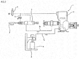
FIG. 1 is a pictorial view for illustrating a structure of a grease application device in accordance with an example of an embodiment of the present invention. -
FIG. 2 is a pictorial view for illustrating a structure of a nozzle and an arrangement aspect of the nozzle to a member to be applied. -
FIG. 3 illustrates a structure of a grease application device of the related art. - An example of an embodiment of the present invention will be described with reference to
FIGS. 1 and2 . A grease application device 1a of the example is to apply grease to worm wheel teeth (a concave-convex part) 11 formed on a circumferential surface of aworm wheel 10 configuring a shaft-mountedworm wheel 9 corresponding to the member to be applied of the claims, and includes adrive unit 12, agrease pump 13, anair tank 14, acontinuous flow valve 15 and agrease application unit 16. - The
drive unit 12 includes aservo motor 17 and achuck 19 fixedly coupled to a tip portion of anoutput shaft 18 of theservo motor 17. Thedrive unit 12 can rotatively drive the shaft-mountedworm wheel 9 with an end portion (a lower end portion inFIG. 1 ) of ashaft member 21 of the shaft-mountedworm wheel 9 being gripped by a grippingpart 20 of thechuck 19. - The
grease pump 13 is configured to supply grease (not shown) stored in a tank (not shown) to the continuous flow valve 15 (which will be described later) by a pump (not shown). Specifically, the grease delivered from thegrease pump 13 is supplied to thecontinuous flow valve 15 through a path of a hose forgrease 22a→adecompression valve 23→a hose forgrease 22b. Adecompression valve 23 is configured to adjust (decompress) a pressure of the grease supplied from thegrease pump 13 and to deliver the same to the hose forgrease 22b. InFIG. 1 , the path of the grease is denoted with a broken line and a path of air (which will be described later) is denoted with a solid line. - The
air tank 14 is configured to supply compressed air to thecontinuous flow valve 15. Specifically, the air compressed in theair tank 14 is supplied to thecontinuous flow valve 15 through a path of a hose forair 24a→a firstelectromagnetic valve 25→a hose for air 24b→a speed regulation valve 26→a hose forair 24c. The firstelectromagnetic valve 25 can switch ON/OFF states of thecontinuous flow valve 15 by switching ON/OFF states of the firstelectromagnetic valve 25. Specifically, when the firstelectromagnetic valve 25 is at an ON state, it is possible to advance a piston configuring thecontinuous flow valve 15. On the other hand, when the firstelectromagnetic valve 25 is at an OFF state, it is possible to retreat the piston configuring thecontinuous flow valve 15. Also, the speed regulation valve 26 is configured to control an operating speed of the continuous flow valve 15 (an advancing speed of the piston, a delivery speed of the grease) by controlling a flow velocity, a flow rate and the like of the air to be sent to thecontinuous flow valve 15. - As the
continuous flow valve 15, a valve having a cylinder for air (not shown), a space for grease demarcated from the cylinder for air and a piston fitted in a cylindrical space consisting of the cylinder for air and the space for grease can be used. The grease is supplied from thegrease pump 13 to the space for grease of thecontinuous flow valve 15. In the meantime, the air is supplied from theair tank 14 to the cylinder for air of thecontinuous flow valve 15. When the air is supplied into the cylinder for air, the piston is advanced and the grease is delivered from a protrusion port of thecontinuous flow valve 15 to the hose for grease 22c. In the example, thecontinuous flow valve 15 is provided with a moving start detection function for detecting an the start of the advance of the piston and a moving end detection function for detecting the end of the advance of the piston. The corresponding functions can be implemented by means of sensors and the like (not shown), for example. The information detected by the moving start detection function and the moving end detection function can be used to control the firstelectromagnetic valve 25 and a second electromagnetic valve 29 (which will be described later). - As described above, the ON/OFF states of the first
electromagnetic valve 25 are switched to switch the ON/OFF states of the air supply to the cylinder for air of thecontinuous flow valve 15. Therefore, the delivery of the grease from thecontinuous flow valve 15 starts upon switching of the firstelectromagnetic valve 25 to the ON state and stops upon switching to the OFF state. Also, it is possible to adjust an advancing speed of the piston (a delivery amount of the grease) by controlling a flow rate, a flow velocity and the like of the air to be supplied to the cylinder for air with the speed regulation valve 26. However, when a pressure in the cylinder for air is low, even though the firstelectromagnetic valve 25 is switched to the ON state, the piston is not advanced until the pressure in the cylinder for air sufficiently increases. Therefore, when the pressure in the cylinder for air is not sufficiently high, a time lag may occur after the firstelectromagnetic valve 25 is switched to the ON state until the piston of thecontinuous flow valve 15 starts to advance. - The
grease application unit 16 includes an opening and closingvalve 27 and anozzle 28. - The opening and closing
valve 27 is switched between ON/OFF states (release/closed states) as the ON/OFF states of the secondelectromagnetic valve 29 are switched. When the opening and closingvalve 27 is at the ON state (a release state and the secondelectromagnetic valve 29 is at the ON state), it is possible to supply the grease supplied from thecontinuous flow valve 15 to thenozzle 28. On the other hand, when the opening and closingvalve 27 is at the OFF state (a closed state and the secondelectromagnetic valve 29 is at the OFF state), the supply of the grease to thenozzle 28 is stopped. - The
nozzle 28 is a cylindrical member. Aninclined part 30 having a flat surface shape that is inclined to the other side (a right side inFIG. 2 ) as it faces towards a tip-side is formed at a circumferential part (a half part of the worm wheel 9-side inFIG. 2 ) of a tip portion (an upper end portion inFIG. 2 ) of thenozzle 28. Specifically, theinclined part 30 has a tip-side inclinedpart 31 formed at a tip portion and a portion close to the tip and a base end-side inclinedpart 32 formed at a portion closer to a base end-side than the tip-side inclined part. An inclination angle θ1 of the tip-side inclinedpart 31 relative to a central axis O of abase part 33 of thenozzle 28 is greater than an inclination angle θ2 of the base end-side inclinedpart 32 relative to the central axis O (θ1>θ2). A tip-side opening 34 of thenozzle 28 opens towards the tip-side inclinedpart 31. In the example, the inclination angle θ1 of the tip-side inclinedpart 31 is regulated to 30°. However, the inclination angle θ1 may be regulated to a range of 20° to 40°, preferably, a range of 25° to 35°. In the example, theinclined part 30 is configured by the tip-side inclinedpart 31 and the base end-side inclinedpart 32 but may also be configured by one inclined surface. - Subsequently, an operation of applying the grease to the
worm wheel teeth 11 of the shaft-mountedworm wheel 9 by the grease application device of the example is described. The grease application operation to be described below is performed in some processes of a line for automatically assembling a worm-type reducer, for example. In the example, as the grease, urea-based grease of which a worked penetration is about 220 to 280 is used. However, a variety of other greases can also be used. - First, the end portion (a lower end portion in F1G. 1) of the
shaft member 21 of the shaft-mountedworm wheel 9 is fixed to thegripping part 20 of thechuck 19 configuring thedrive unit 12 by a conveyor device (not shown). - Then, the
servo motor 17 configuring thedrive unit 12 is driven to rotate the shaft-mountedworm wheel 9 with a predetermined number of rotations (rotating speed). The rotation states (a phase, the number of rotations and the like) of the shaft-mountedworm wheel 9 are detected from information of an encoder provided for theservo motor 17. - Then, at a state where the rotating speed of the shaft-mounted
worm wheel 9 detected on the basis of the encoder information is constant, the firstelectromagnetic valve 25 is switched to the ON state, so that thecontinuous flow valve 15 is switched to the ON state (operating state). - Also, the second
electromagnetic valve 29 is switched to the ON state simultaneously with or slightly later (about 0.1 second) than the switching of the firstelectromagnetic valve 25 to the ON state, so that the opening and closingvalve 27 is set to the ON state (release state). Preferably, the secondelectromagnetic valve 29 is switched to the ON in a state where the pressure in the hose for grease 22c is high. In the example, the secondelectromagnetic valve 29 is switched to the ON state simultaneously with or slightly later than the switching of the firstelectromagnetic valve 25 to the ON state. However, the secondelectromagnetic valve 29 may be switched to the ON state after checking that the piston configuring thecontinuous flow valve 15 has started to advance on the basis of the information detected by the moving start detection function. When this configuration is adopted, the secondelectromagnetic valve 29 may be switched to the ON state simultaneously with or later than the detection of the advancing of the piston by the moving start detection function by predetermined time. According to this configuration, when there is a time lag after the firstelectromagnetic valve 25 is switched to the ON state until the piston of thecontinuous flow valve 15 starts to advance, the timing at which the secondelectromagnetic valve 29 is to be switched to the ON state (the opening and closingvalve 27 becomes ON) becomes earlier, so that it is possible to prevent the pressure in the hose for grease 22c from being lowered. - As described above, when the
continuous flow valve 15 is switched to the ON state, the air is supplied to the cylinder for air configuring thecontinuous flow valve 15, so that the piston configuring thecontinuous flow valve 15 starts to advance. As the piston advances, the grease delivered from thecontinuous flow valve 15 passes through the opening and closingvalve 27, flows out of the tip-side opening 34 of thenozzle 28, as a fluid of liquid or gel phase, and is then applied to theworm wheel teeth 11 of the shaft-mountedworm wheel 9. The advancing speed of the piston is adjusted to a predetermined speed by adjusting the flow rate, the flow velocity and the like of the air supplied from the speed regulation valve 26 to predetermined values. - Also, the advancing speed of the piston and the rotating speed of the shaft-mounted
worm wheel 9 are adjusted so that a required time period (an operating time period of the continuous flow valve 15) after the piston starts to advance (the firstelectromagnetic valve 25 is switched to the ON state) until the piston stops (the firstelectromagnetic valve 25 is switched to the OFF state) and a time period (a workpiece rotation time period) for which the shaft-mountedworm wheel 9 rotates one revolution with respect to thenozzle 28 are the same. That is, the application of the greases is ended at a point of time at which the shaft-mountedworm wheel 9 has rotated one revolution with respect to thenozzle 28. In the example, a controller (not shown) is provided so as to make the piston operating time period and the workpiece rotation time period be the same. As a method of regulating the piston operating time period and the workpiece rotation time period to be the same, a variety of methods including an electrical control method and a mechanically synchronizing method may be adopted. - In the example, the tip-side inclined
part 31 of thenozzle 28 is provided to closely face a position at which a tangential line P of the tooth tip circle α of the shaft-mountedworm wheel 9 is the same as the inclination angle θ1 of the tip-side inclinedpart 31 relative to the central axis O of thebase part 33 of thenozzle 28. That is, thenozzle 28 is mounted so that an inclination direction of the inclined surface of the tip-side inclinedpart 31 is parallel with a tangential direction of the tooth tip circle passing tooth tips (tip portions of convex portions) of theworm wheel 9. In the example, a distance L between the tip-side inclinedpart 31 and the tooth tip circle of theworm wheel teeth 11 of the shaft-mountedworm wheel 9 is regulated to 2mm. However, the distance L can be regulated to a range of 1 mm to 3mm, preferably, a range of 1.5mm to 2.5mm. In this way, the tip-side inclined part 31 (the tip-side opening 34) of thenozzle 28 inclined at a predetermined angle is made to closely face theworm wheel teeth 11 of the shaft-mountedworm wheel 9, as described above, so that it is possible not only to simply apply (attach) the grease, which is a fluid of liquid or gel phase discharged from the tip-side opening 34, to theworm wheel teeth 11 but also to fill the attached grease while pushing the grease into concave portions of the worm wheel teeth 11 (bottom portions of teeth) by the tip-side inclinedpart 31. - As described above, after applying the grease only while the shaft-mounted
worm wheel 9 rotates one revolution with respect to thenozzle 28, the first and secondelectromagnetic valves servo motor 17 is stopped to reduce the rotation of the shaft-mountedworm wheel 9. Thereafter, after checking that the rotation of the shaft-mountedworm wheel 9 has stopped on the basis of the encoder information of theservo motor 17, the shaft-mountedworm wheel 9 is conveyed to a next processor by the conveyor device. - In the example configured as described above, the shape of the
nozzle 28 is improved and the arrangement aspect of the nozzle to the shaft-mountedworm wheel 9 is regulated as described above. While the shaft-mountedworm wheel 9 rotates one revolution, it is possible to fill the liquid grease while pushing the grease into the concave portions of theworm wheel teeth 11 of the shaft-mounted worm wheel 9 (the bottom portions of the teeth) by thenozzle 28. For this reason, it is possible to apply a sufficient amount of the grease to theworm wheel teeth 11 of the shaft-mountedworm wheel 9 in a short time. - Then, the rotation position of the
worm wheel 9 is detected, so that it is possible to adjust an amount of the grease to be applied to the rotation position, in correspondence to the detected rotation position of theworm wheel 9. - According to the grease application method and the grease application device of the present invention, it is possible to apply the grease not only to the worm wheel but also to a variety of gear members having a concave-convex part formed on an inner or outer peripheral surface thereof.
- Also, when implementing the grease application method and the grease application device of the present invention, the opening and closing valve configuring the grease application device may be omitted.
- Also, when implementing the grease application method and the grease application device of the present invention, if the air to be supplied to the continuous flow valve can be stably secured without using the air tank, the air tank may be omitted.
- Also, in the above embodiment, the operating time period of the continuous flow valve and the workpiece rotation time period are regulated to be the same by the controller. However, instead of the continuous flow valve and the speed regulation valve, a continuous flow valve configured to drive by a screw mechanism, such as an electric gear-type continuous flow valve (for example, a mono pump (registered trademark), may also be adopted.
- Also, in the above embodiment, the member to be applied is enabled to rotate at a constant speed and the flow rate of the grease to be discharged from the nozzle to the member to be applied is constant. However, it may also be possible to apply the grease while changing the rotating speed of the member to be applied, at a state where the flow rate of the grease to be discharged from the nozzle is maintained to be constant. Specifically, while detecting a phase of the member to be applied, the rotating speed of the workpiece is slowed down when the opening of the nozzle faces the concave portions (tooth bottom surfaces of the worm wheel teeth) of the concave-convex part (the worm wheel teeth) of the member to be applied (the worm wheel). According to this configuration, it is possible to apply the grease while filling the grease into the concave portions of the concave-convex part of the workpiece.
- The present invention is based on a Japanese Patent Application No.
2015-39863 filed on March 2, 2015 -
- 1a: grease application device
- 9: shaft-mounted worm wheel
- 10: worm wheel
- 11: worm wheel teeth
- 12: drive unit
- 16: grease application unit
- 17: servo motor
- 28: nozzle
- 30: inclined part
- 31: tip-side inclined part
- 32: base end-side inclined part
- 34: tip-side opening
Claims (11)
- A grease application device comprising:a drive unit configured to rotatively drive a member to be applied, anda nozzle of which an opening is arranged close to a concave-convex part formed on a circumferential surface of the member to be applied, and configured to apply grease which is discharged from the opening to the concave-convex part,wherein the grease is applied from the nozzle to the member to be applied, as a fluid of liquid or gel phase, andwherein the nozzle is provided to apply the grease to the concave-convex part while pushing the grease into concave portions of the concave-convex part.
- The grease application device according to claim 1,
wherein a tip portion of the nozzle is formed with an inclined surface inclined relative to a central axis of the nozzle by a predetermined angle,
wherein the opening of the nozzle is open towards the inclined surface, and
wherein the grease is applied at a state where the opening closely faces the concave-convex part. - The grease application device according to claim 1 or 2 comprising a function of ending an application of the grease at a point of time at which the member to be applied has rotated one revolution with respect to the nozzle after starting the application of the grease to the member to be applied.
- The grease application device according to any one of claims 1 to 3 comprising:a detection function of detecting a rotation position of the member to be applied, anda function of adjusting an amount of the grease to be applied to the rotation position, in correspondence to the rotation position of the member to be applied detected by the detection function.
- A grease application method of while rotating a member to be applied having a concave-convex part formed on a circumferential surface thereof, applying grease, which is discharged from an opening of a nozzle arranged closed to the concave-convex part, to the concave-convex part,
wherein the grease, which is a fluid of liquid or gel phase, is applied to the concave-convex part by the nozzle while pushing the grease into bottom portions of concave portions of the concave-convex part. - The grease application method according to claim 5,
wherein an application of the grease is ended at a point of time at which the member to be applied has rotated one revolution with respect to the nozzle after starting the application of the grease to the concave-convex part of the member to be applied. - The grease application method according to claim 5 or 6,
wherein a tip portion of the nozzle is formed with an inclined surface inclined relative to a central axis of the nozzle by a predetermined angle,
wheren the opening of the nozzle is open towards the inclined surface, and
wherein the grease is applied at a state where the opening closely faces the concave-convex part. - The grease application method according to claim 7,
wherein the nozzle is provided so that an inclination direction of the inclined surface is parallel with a tangential direction of a tooth tip circle passing tip portions of convex portions of the concave-convex part of the member to be applied. - The grease application method according to any one of claims 5 to 8,
whrein a rotation position of the member to be applied is detected after starting an application of the grease, and
wherein an amount of the grease corresponding to the rotation position of the member to be applied is applied. - The grease application method according to claim 9,
wherein the amount of the grease corresponding to the rotation position of the member to be applied is applied by changing a rotating speed of the member to be applied while constantly keeping an amount of the grease to be discharged from the opening of the nozzle. - The grease application method according to claim 10,
wherein when the concave portions of the concave-convex part of the member to be applied face the opening of the nozzle, the grease is applied to be filled in the concave portions by slowing down the rotating speed of the member to be applied.
Applications Claiming Priority (2)
| Application Number | Priority Date | Filing Date | Title |
|---|---|---|---|
| JP2015039863A JP6265152B2 (en) | 2015-03-02 | 2015-03-02 | Grease application method and application device, worm speed reducer manufacturing method, electric power steering device manufacturing method, automobile manufacturing method and industrial machine manufacturing method |
| PCT/JP2016/055077 WO2016140095A1 (en) | 2015-03-02 | 2016-02-22 | Grease application method and application device |
Publications (2)
| Publication Number | Publication Date |
|---|---|
| EP3267090A1 true EP3267090A1 (en) | 2018-01-10 |
| EP3267090A4 EP3267090A4 (en) | 2018-04-18 |
Family
ID=56846418
Family Applications (1)
| Application Number | Title | Priority Date | Filing Date |
|---|---|---|---|
| EP16758789.8A Withdrawn EP3267090A4 (en) | 2015-03-02 | 2016-02-22 | Grease application method and application device |
Country Status (5)
| Country | Link |
|---|---|
| US (1) | US10119608B2 (en) |
| EP (1) | EP3267090A4 (en) |
| JP (1) | JP6265152B2 (en) |
| CN (1) | CN107407459B (en) |
| WO (1) | WO2016140095A1 (en) |
Families Citing this family (10)
| Publication number | Priority date | Publication date | Assignee | Title |
|---|---|---|---|---|
| JP6187496B2 (en) * | 2015-02-16 | 2017-08-30 | 日本精工株式会社 | Grease application nozzle |
| CN107744905A (en) * | 2017-11-20 | 2018-03-02 | 杭州冠南耐磨材料有限公司 | A kind of automatic painting system |
| CN107952601A (en) * | 2017-12-19 | 2018-04-24 | 新乡市恒星科技有限责任公司 | A kind of lubricating grease coating nozzle |
| CN108506466A (en) * | 2018-04-03 | 2018-09-07 | 青岛宏达锻压机械有限公司 | Electric screw press gear pair automatic lubricating system |
| DE102019106692B4 (en) * | 2019-03-15 | 2023-04-13 | Perma-Tec Gmbh & Co. Kg | lubricator |
| JP7358124B2 (en) * | 2019-09-06 | 2023-10-10 | 川崎重工業株式会社 | Greasing device for board transfer equipment |
| CN114719169B (en) * | 2022-03-22 | 2023-12-08 | 陕西法士特齿轮有限责任公司 | Automatic molybdenum disulfide lubricating grease spraying mechanism for main shaft gear pressing plate of gearbox auxiliary box |
| CN116753446A (en) * | 2023-06-06 | 2023-09-15 | 山东飞越电子科技有限公司 | A grease adding device for pan/tilt worm gear |
| CN118705357B (en) * | 2024-08-30 | 2024-11-22 | 杭州沃克士传动科技有限公司 | A reducer |
| CN118881726B (en) * | 2024-09-25 | 2024-12-10 | 江苏凯斯盾科技有限公司 | Gear box structure for pedal motor |
Family Cites Families (30)
| Publication number | Priority date | Publication date | Assignee | Title |
|---|---|---|---|---|
| US2017871A (en) * | 1932-04-01 | 1935-10-22 | Hoe & Co R | Lubricant spreader for gears |
| US2220301A (en) * | 1939-05-04 | 1940-11-05 | Ingersoll Rand Co | Oiling device |
| US2235258A (en) * | 1940-06-25 | 1941-03-18 | Fog Nozzle Co | Fire extinguishing nozzle |
| JPS60104276U (en) * | 1983-12-20 | 1985-07-16 | トキコ株式会社 | Application nozzle |
| US4815637A (en) * | 1988-04-21 | 1989-03-28 | Nellis Russell L | Cap assembly for use with canned aerosol lubricant |
| US4901679A (en) * | 1988-09-30 | 1990-02-20 | Stanadyne Automotive Corp. | Spray nozzle assembly for piston cooling |
| DE4436505A1 (en) * | 1994-10-13 | 1996-04-18 | Zahnradfabrik Friedrichshafen | Automatic transmissions, in particular for motor vehicles |
| SE513665C2 (en) * | 1995-09-25 | 2000-10-16 | Aplicator System Ab | Nozzle for dispensing of thermosetting resin and hardener |
| US5890661A (en) * | 1996-11-27 | 1999-04-06 | Par-Way Group | Colliding stream spray dispensing system with a moldable nozzle |
| TW344682B (en) * | 1996-11-29 | 1998-11-11 | Fuji Transaction Co Ltd | Liquid coating device a liquid coating device comprises a spray supply nozzle, a gas supply passage, and a spray transport passage. |
| US6659370B1 (en) * | 1998-05-25 | 2003-12-09 | Fuji Bc Engineering Co., Ltd. | Liquid spray device and cutting method |
| US6921680B2 (en) * | 2001-12-31 | 2005-07-26 | Texas Instruments Incorporated | Method and apparatus for MEMS device nebulizer lubrication system |
| US7374019B2 (en) * | 2002-03-05 | 2008-05-20 | Ntn Corporation | Method of and device for lubricating rolling bearings |
| ITMI20030676A1 (en) * | 2003-04-07 | 2004-10-08 | Auges S R L | DEVICE AND METHOD TO DELIVER A LUBRICANT AND / OR REFRIGERANT FLUID IN MECHANICAL PROCESSING |
| DE10321535B3 (en) * | 2003-05-14 | 2004-10-28 | Repower Systems Ag | Mechanism to set the rotor angle, at a wind energy generator, has a lubricating pinion at the rim gear or drive cogwheel to transfer a dose of lubricant without interrupting its working |
| KR100692125B1 (en) * | 2003-10-30 | 2007-03-12 | 현대자동차주식회사 | Belt Lubrication Control of Stepless Transmission |
| US7122220B1 (en) * | 2003-11-12 | 2006-10-17 | Bridgestone Firestone North American Tire, Llc | Method and apparatus for protecting innerliner of a green tire |
| US7699932B2 (en) * | 2004-06-02 | 2010-04-20 | Micron Technology, Inc. | Reactors, systems and methods for depositing thin films onto microfeature workpieces |
| JP5188961B2 (en) * | 2005-05-20 | 2013-04-24 | グルンドフォス ノノックス エー/エス | Fluid atomization method by mutual collision of fluid streams, nozzle therefor, and system including the same |
| JP4424293B2 (en) * | 2005-09-29 | 2010-03-03 | 株式会社ジェイテクト | Rolling bearing device |
| US7219849B1 (en) * | 2005-12-13 | 2007-05-22 | Graves Spray Supply, Inc. | Liquid impingement nozzle with paired openings |
| DE102006013865B4 (en) * | 2006-03-23 | 2007-11-22 | Zs Schmieranlagen Vertriebs-Gmbh & Co. Kg | Gear lubrication module for the automatic lubrication of gears, in particular wind turbines |
| US20080149424A1 (en) * | 2006-12-24 | 2008-06-26 | Jen-Sheng Chen | Adjusting structure for an oil feeding device of a linear guideway |
| US8074543B2 (en) * | 2007-03-01 | 2011-12-13 | Mori Seiki Usa, Inc. | Machine tool with cooling nozzle and method for applying cooling fluid |
| JP2010269892A (en) * | 2009-05-21 | 2010-12-02 | Sanden Corp | Device for lubricating chain |
| JP5382030B2 (en) * | 2011-02-23 | 2014-01-08 | アイシン・エィ・ダブリュ株式会社 | Friction plate lubrication device for automatic transmission |
| JP2012217952A (en) * | 2011-04-11 | 2012-11-12 | Mitsuba Corp | Spray type coating apparatus |
| CN103477124B (en) * | 2011-04-20 | 2016-11-23 | 丰田自动车株式会社 | The oil feeding device of power transmission |
| JP5790138B2 (en) * | 2011-05-11 | 2015-10-07 | トヨタ自動車株式会社 | Lubricating oil supply device |
| JP2013210002A (en) * | 2012-03-30 | 2013-10-10 | Nsk Ltd | Rolling bearing device with lubricant supply mechanism |
-
2015
- 2015-03-02 JP JP2015039863A patent/JP6265152B2/en active Active
-
2016
- 2016-02-22 US US15/548,865 patent/US10119608B2/en active Active
- 2016-02-22 CN CN201680012914.7A patent/CN107407459B/en active Active
- 2016-02-22 WO PCT/JP2016/055077 patent/WO2016140095A1/en not_active Ceased
- 2016-02-22 EP EP16758789.8A patent/EP3267090A4/en not_active Withdrawn
Also Published As
| Publication number | Publication date |
|---|---|
| CN107407459B (en) | 2019-12-10 |
| JP6265152B2 (en) | 2018-01-24 |
| CN107407459A (en) | 2017-11-28 |
| EP3267090A4 (en) | 2018-04-18 |
| US20180045296A1 (en) | 2018-02-15 |
| JP2016161033A (en) | 2016-09-05 |
| US10119608B2 (en) | 2018-11-06 |
| WO2016140095A1 (en) | 2016-09-09 |
Similar Documents
| Publication | Publication Date | Title |
|---|---|---|
| US10119608B2 (en) | Grease application method, application device, and methods for manufacturing worm-type reducer, electric power steering device, automobile and variety of industrial machines | |
| JP6304617B2 (en) | Fluid application system and fluid application method | |
| EP1293307A3 (en) | Method and apparatus for operating a clamp in automatic manipulators | |
| EP3677344B1 (en) | Viscous material stirring device and viscous material stirring method | |
| CN204958358U (en) | Conveying device for medicine bottles | |
| MY187235A (en) | Product dispensing device | |
| JP6326598B2 (en) | Fluid application system and fluid application method | |
| EP2907644A1 (en) | Injection unit and injection molding method | |
| CN108290728A (en) | For filling and the device and method of sealing container | |
| FI124392B (en) | Method for using a SWING type mixer as well as a mixer | |
| JP6877874B2 (en) | Winding device | |
| US11090748B2 (en) | Device adapted to dosing pasty substances | |
| CN109382256B (en) | Liquid supply equipment | |
| RS63264B1 (en) | DIFFERENTIAL IMPULSE TRANSPORTER AND METHOD OF CARRYING THE SAME | |
| JP7652924B2 (en) | SYSTEM AND METHOD FOR PERFORMING ASSEMBLY TASKS USING A ROBOT - Patent application | |
| JP6441175B2 (en) | Sealant coating apparatus and method for producing sealant coated product | |
| FR3079770B1 (en) | MIXING APPARATUS FOR WET OR DRY MATERIALS, PARTICULARLY COMPONENTS FOR THE MANUFACTURE OF CONCRETE | |
| EP2942289A1 (en) | Filling device and method for an automatic horizontal flexible container forming and filling machine | |
| KR101602831B1 (en) | paste dispenser | |
| SE545142C2 (en) | Valve control device with perpendicular axes | |
| WO2010097283A3 (en) | Device and method for dispensing free-flowing materials in particular for injecting highly viscous materials between workpieces | |
| JP2008264688A (en) | Coating mixer and coating machine equipped with it | |
| GB2548691A8 (en) | End effector for a robot | |
| JP2013173551A (en) | Surface treatment method for contents filled in container and device therefor | |
| EP3178779A1 (en) | Apparatus and method for sealing containers |
Legal Events
| Date | Code | Title | Description |
|---|---|---|---|
| PUAI | Public reference made under article 153(3) epc to a published international application that has entered the european phase |
Free format text: ORIGINAL CODE: 0009012 |
|
| 17P | Request for examination filed |
Effective date: 20170830 |
|
| AK | Designated contracting states |
Kind code of ref document: A1 Designated state(s): AL AT BE BG CH CY CZ DE DK EE ES FI FR GB GR HR HU IE IS IT LI LT LU LV MC MK MT NL NO PL PT RO RS SE SI SK SM TR |
|
| AX | Request for extension of the european patent |
Extension state: BA ME |
|
| A4 | Supplementary search report drawn up and despatched |
Effective date: 20180321 |
|
| RIC1 | Information provided on ipc code assigned before grant |
Ipc: F16N 7/38 20060101ALI20180315BHEP Ipc: F16H 57/04 20100101ALI20180315BHEP Ipc: B05B 12/00 20180101ALI20180315BHEP Ipc: F16N 7/14 20060101ALI20180315BHEP Ipc: F16N 11/08 20060101AFI20180315BHEP |
|
| DAV | Request for validation of the european patent (deleted) | ||
| DAX | Request for extension of the european patent (deleted) | ||
| 17Q | First examination report despatched |
Effective date: 20181210 |
|
| GRAP | Despatch of communication of intention to grant a patent |
Free format text: ORIGINAL CODE: EPIDOSNIGR1 |
|
| INTG | Intention to grant announced |
Effective date: 20200415 |
|
| STAA | Information on the status of an ep patent application or granted ep patent |
Free format text: STATUS: THE APPLICATION IS DEEMED TO BE WITHDRAWN |
|
| 18D | Application deemed to be withdrawn |
Effective date: 20200826 |