EP3267053B1 - Karabiner - Google Patents
Karabiner Download PDFInfo
- Publication number
- EP3267053B1 EP3267053B1 EP17175458.3A EP17175458A EP3267053B1 EP 3267053 B1 EP3267053 B1 EP 3267053B1 EP 17175458 A EP17175458 A EP 17175458A EP 3267053 B1 EP3267053 B1 EP 3267053B1
- Authority
- EP
- European Patent Office
- Prior art keywords
- gate
- thimble
- gate bar
- bar
- carabiner
- Prior art date
- Legal status (The legal status is an assumption and is not a legal conclusion. Google has not performed a legal analysis and makes no representation as to the accuracy of the status listed.)
- Active
Links
Images


Classifications
-
- F—MECHANICAL ENGINEERING; LIGHTING; HEATING; WEAPONS; BLASTING
- F16—ENGINEERING ELEMENTS AND UNITS; GENERAL MEASURES FOR PRODUCING AND MAINTAINING EFFECTIVE FUNCTIONING OF MACHINES OR INSTALLATIONS; THERMAL INSULATION IN GENERAL
- F16B—DEVICES FOR FASTENING OR SECURING CONSTRUCTIONAL ELEMENTS OR MACHINE PARTS TOGETHER, e.g. NAILS, BOLTS, CIRCLIPS, CLAMPS, CLIPS OR WEDGES; JOINTS OR JOINTING
- F16B45/00—Hooks; Eyes
- F16B45/02—Hooks with pivoting or elastically bending closing member
- F16B45/027—Hooks with pivoting or elastically bending closing member and having position-locking means for the closing member
- F16B45/029—Hooks with pivoting or elastically bending closing member and having position-locking means for the closing member the position-locking means being slidably mounted
-
- F—MECHANICAL ENGINEERING; LIGHTING; HEATING; WEAPONS; BLASTING
- F16—ENGINEERING ELEMENTS AND UNITS; GENERAL MEASURES FOR PRODUCING AND MAINTAINING EFFECTIVE FUNCTIONING OF MACHINES OR INSTALLATIONS; THERMAL INSULATION IN GENERAL
- F16B—DEVICES FOR FASTENING OR SECURING CONSTRUCTIONAL ELEMENTS OR MACHINE PARTS TOGETHER, e.g. NAILS, BOLTS, CIRCLIPS, CLAMPS, CLIPS OR WEDGES; JOINTS OR JOINTING
- F16B45/00—Hooks; Eyes
- F16B45/02—Hooks with pivoting or elastically bending closing member
- F16B45/023—Hooks with pivoting or elastically bending closing member the closing member pivoting about an axis perpendicular to the plane of the hook
Definitions
- the present invention relates to screwgate carabiners.
- a screwgate carabiner is a type of carabiner that allows an openable grate to be secured in a closed position by a screw-threaded thimble.
- Such carabiners are well-known (cf. FR 2 803 343 A1 ) and their general configuration will be described below.
- the thimble has an internal thread that is in operative engagement with an external thread of a component of the gate on which the thimble is carried.
- the threads are formed such that at a closed position, the thimble can be tightened to cause the crest of one thread to bottoms-out in the root of the other, so as to resist mutual rotation of the threaded components by friction.
- a problem can arise with screwgate carabiners where, if the gate is tightened firmly, it can jam, making loosening difficult for a user.
- An aim of this invention is to provide a screwgate carabiner which is less likely to jam in the closed position than conventional screwgate carabiners.
- the invention provides a gate for a carabiner comprising a gate bar and a locking thimble, the gate bar and the locking thimble being interconnected by interengaging screw threads whereby their mutual rotation about an axis causes the thimble to move axially along the gate bar between an open position and a closed position, wherein each of the gate bar and the locking thimble carries abutments that extend circumferentially about the axis, which abutments come into contact with one another when the thimble is in the closed position.
- Each abutment is preferably disposed in a plane that extends normally to the axis: that is to say, the abutments are not helical. In a typical embodiment, one of or both of the abutments extends in a continuous loop about the axis.
- the abutment of the thimble projects radially inwardly into an axial passage that extends through the thimble.
- the abutment of the gate bar may be a rib that projects radially (i.e., at least, a component of the projection direction is radial) from an outer surface of the gate bar.
- One or both of the gate bar and the thimble may be anodised.
- This invention may find particular advantage where the anodisation layer has a thickness of 8-20 ⁇ m, and in particular where the anodisation layer is in excess of 15 ⁇ m.
- the colour of anodisation of one or both components may be black. It will, however, be noted that embodiments of this invention can be used where there is no problem with jamming. Since it is not significantly harder or more expensive to manufacture than a conventional gate, this means that a gate embodying the invention can be considered to be a universal component of wider application than conventional carabiner gates.
- this invention provides a carabiner a body and a gate according to any preceding claim pivotally connected to the body.
- the abutments are typically disposed between the screw threads and the connection with the body.
- the carabiner comprises a body 10 which can take a variety of forms, but which is invariably generally C-shaped within a median plane.
- the body has a pivot end portion 12 and a free end portion 14 that are spaced apart and extend generally towards one another.
- a gate 20 is carried on the body.
- the gate 20 comprises a gate bar 22 that has one end portion connected to the pivot end 12 of the body 10, such that the gate bar 22 can pivot with respect to the body 10, within the median plane, between a closed position (as shown in Figure 1 ) and an open position.
- the gate bar 22 is connected to the body 10 by a pivot pin 16 that passes through holes 28 in the gate bar 22.
- the gate bar 22 makes contact with the free end 14 of the body 10, whereby the body 10 and the gate bar 22 form a continuous loop, a flattened end portion of the body 10 entering into a slot 26 formed in the gate bar 22.
- An enclosed space 24 is therefore defined within the carabiner when the gate 20 is in the closed position.
- the gate bar 22 In the open position, the gate bar 22 is pivotally displaced such that there is a space between the free end 14 of the body 10 and the gate, such that the body 10 and the gate 20 are discontinuous, providing an opening into the space within the carabiner.
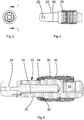
- the gate 20 further comprises a tubular locking thimble 30 carried on and surrounding the gate bar 22.
- the thimble 30 can be caused to advance axially along the gate bar 22 in a direction away from the pivot end 12 of the body 10, such that an end portion of the thimble 30 surrounds part of the slot 26 and the free end 14 of the body 10 therein. With the thimble 30 this position, the gate 20 cannot be opened because the thimble 30 prevents the free end 14 of the body 10 from leaving the slot 26.
- Each of the body 10 the gate bar 22 and the thimble 30 are formed as one-piece anodised components of a lightweight metal alloy.
- the anodising coating of each component is black in colour and approximately 15-20 ⁇ m thick.
- Rotation of the thimble 30 on the gate bar 22 in a first direction causes the thimble 30 to move towards the pivot pin 16 until it clears the slot 26 sufficiently to allow the free end 14 of the body to pass out of the slot 26 as the gate 20 is opened. Movement of the thimble 30 in this direction is limited by a circlip 34 retained in a peripheral groove 36 on the gate bar 22.
- Rotation of the thimble 30 on the gate bar 22 in a second, opposite direction causes the thimble to move away from the pivot pin 16 to a locking position. If this is done with the gate 20 in the closed position, the free end 14 of the body becomes trapped in the slot 26 thus preventing the gate from opening.
- the thimble 30 and gate bar 22 must be configured such that when it is in the locking position it is retained there sufficiently firmly to prevent its accidental or spontaneous movement away from that position, but not so firmly as to prevent intentional movement by a user.
- a projecting circumferential rib 42 is provided on the gate bar 22 to constitute an abutment between the thread 40 and the pivot pin 16.
- a cooperating part 44 of the thimble 30 has a cylindrical section that constitutes an abutment, and that closely surrounds a cylindrical portion 46 of the gate bar 22 that extends between the thread 40 and the pivot. The radius of the abutment 44 being such that it is of insufficient size to pass axially across the rib 42.
- the abutment 44 makes contact with the rib 42 to prevent further rotation.
- the thimble 30 can then be tightened against the rib 42 such that mutual friction between the rib 42 and the abutment 44 resists movement of the thimble 30 away from the locking position.
- the dimeter of the portion 46 of the gate bar 22 between the abutment 44 and the pivot is such that it may pass closely through the abutment 44 of the thimble 30.
- the thimble 30 can be installed onto the gate bar 22 by sliding it onto the gate bar 22 from the pivot and, and then rotating the thimble 30 to case the threads 40 to interengage. The thimble 30 is then advanced along the locking bar 22 until it clears the groove 36, whereupon it can be secured by application of a circlip 34. This completes the assembly of the gate.
- a carabiner can then be completed by inserting a return spring assembly into the gate bar 22, and then connecting to gate 20 to the body 10 by inserting the pin 16 through the holes 28 in the gate bar and a corresponding hole in the pivot end of the body 10.
Landscapes
- Engineering & Computer Science (AREA)
- General Engineering & Computer Science (AREA)
- Mechanical Engineering (AREA)
- Hooks, Suction Cups, And Attachment By Adhesive Means (AREA)
Claims (11)
- Verschluss für einen Karabiner, umfassend eine Verschlussstrebe (22) und eine Verriegelungskausche (30), wobei die Verschlussstrebe (22) und die Verriegelungskausche (30) miteinander verbunden sind, indem Schraubengewinde (40) miteinander in Eingriff genommen werden, wodurch ihre gemeinsame Drehung um eine Achse bewirkt, dass sich die Kausche (30) axial entlang der Verschlussstrebe zwischen einer offenen Position und einer geschlossenen Position bewegt, dadurch gekennzeichnet, dass jede von der Verschlussstrebe (22) und der Verriegelungskausche (30) Widerlager (42, 44) trägt, die sich umlaufend um die Achse erstrecken, wobei die Widerlager (42, 44) miteinander in Kontakt kommen, wenn sich die Kausche (30) in der geschlossenen Position befindet.
- Verschluss nach Anspruch 1, wobei jedes Widerlager (42, 44) in einer Ebene angeordnet ist, die sich senkrecht zu der Achse erstreckt.
- Verschluss nach Anspruch 1 oder Anspruch 2, wobei sich eines oder beide der Widerlager (42, 44) in einer durchgehenden Schlaufe um die Achse erstrecken.
- Verschluss nach einem vorhergehenden Anspruch, wobei das Widerlager (44) der Kausche (30) radial einwärts in einen axialen Durchlass ragt, der sich durch die Kausche erstreckt.
- Verschluss nach einem vorhergehenden Anspruch, wobei das Widerlager (42) der Verschlussstrebe (22) eine Rippe ist, die radial von einer Außenfläche der Verschlussstrebe ragt.
- Verschluss nach einem vorhergehenden Anspruch, wobei eine oder beide von der Verschlussstrebe (22) und der Kausche (30) anodisiert sind.
- Verschluss nach Anspruch 6, wobei die Anodisation eine Schicht ist, die eine Dicke in der Spanne von 8-20 µm aufweist.
- Verschluss nach Anspruch 6, wobei die Anodisation eine Schicht ist, die eine Dicke von mehr als 15 µm aufweist.
- Verschluss nach einem der Ansprüche 6 bis 8, wobei die Farbe der Anodisation von einer oder beiden von der Verschlussstrebe (22) und der Kausche (30) schwarz ist.
- Karabiner, umfassend einen Körper (10) und einen Verschluss (20) nach einem vorhergehenden Anspruch, der schwenkbar mit dem Körper verbunden ist.
- Karabiner nach Anspruch 10, wobei die Widerlager zwischen den Schraubengewinden und der Verbindung mit dem Körper angeordnet sind.
Applications Claiming Priority (1)
| Application Number | Priority Date | Filing Date | Title |
|---|---|---|---|
| GB1611706.1A GB2553268B (en) | 2016-07-05 | 2016-07-05 | Screwgate carabiner |
Publications (2)
| Publication Number | Publication Date |
|---|---|
| EP3267053A1 EP3267053A1 (de) | 2018-01-10 |
| EP3267053B1 true EP3267053B1 (de) | 2018-12-05 |
Family
ID=56891090
Family Applications (1)
| Application Number | Title | Priority Date | Filing Date |
|---|---|---|---|
| EP17175458.3A Active EP3267053B1 (de) | 2016-07-05 | 2017-06-12 | Karabiner |
Country Status (2)
| Country | Link |
|---|---|
| EP (1) | EP3267053B1 (de) |
| GB (1) | GB2553268B (de) |
Families Citing this family (1)
| Publication number | Priority date | Publication date | Assignee | Title |
|---|---|---|---|---|
| TWI733175B (zh) * | 2019-08-28 | 2021-07-11 | 振鋒企業股份有限公司 | 絕緣卡賓鉤之固定銷孔的成型方法 |
Family Cites Families (5)
| Publication number | Priority date | Publication date | Assignee | Title |
|---|---|---|---|---|
| JPS51163357U (de) * | 1975-06-20 | 1976-12-25 | ||
| JPS582920Y2 (ja) * | 1980-08-01 | 1983-01-19 | 伊藤 勝通 | カラビナ |
| JPH0234492Y2 (de) * | 1987-07-22 | 1990-09-17 | ||
| FR2803343B1 (fr) * | 1999-12-31 | 2002-08-16 | Decathlon Sa | Ensemble de deux pieces coulissantes avec systeme de reperage sonore et tactile, et mousqueton comprenant un tel ensemble |
| KR101374809B1 (ko) * | 2012-09-18 | 2014-03-17 | 김인숙 | 카라비너 |
-
2016
- 2016-07-05 GB GB1611706.1A patent/GB2553268B/en active Active
-
2017
- 2017-06-12 EP EP17175458.3A patent/EP3267053B1/de active Active
Non-Patent Citations (1)
| Title |
|---|
| None * |
Also Published As
| Publication number | Publication date |
|---|---|
| GB201611706D0 (en) | 2016-08-17 |
| EP3267053A1 (de) | 2018-01-10 |
| GB2553268A (en) | 2018-03-07 |
| GB2553268B (en) | 2018-11-28 |
Similar Documents
| Publication | Publication Date | Title |
|---|---|---|
| US7540074B2 (en) | Carabiner having reinforcing sleeve | |
| KR101924914B1 (ko) | 신속 체결기, 이 신속 체결기에 의해 두 부품을 연결하기 위한 방법, 및 신속 체결기 제조 방법 | |
| JP3917122B2 (ja) | バンパーシステム | |
| US20170015016A1 (en) | Quick connect mechanism for a draw stud assembly | |
| US2919736A (en) | Threaded fastener retaining device | |
| WO2014093025A2 (en) | Ratcheting anti-rotation lock for threaded connectors | |
| US8966874B2 (en) | Shackle assembly with locking pin | |
| US20120301247A1 (en) | Locking threaded fastener | |
| EP1024324A2 (de) | Vorrichtung zur Kopplung eines Ventilkörpers oder Ähnlichem mit einem Verbindungsstück | |
| EP2341256A2 (de) | Haken mit Feder und Anzeiger | |
| EP3267053A1 (de) | Karabiner | |
| US12305698B2 (en) | Socket assembly with antirotation spring washer | |
| US9462919B2 (en) | Damper locking mechanism for toilet seat | |
| US20130061712A1 (en) | Knob Assembly | |
| CN118140056A (zh) | 具有固定元件的棘爪螺母 | |
| US10962160B2 (en) | Camlock | |
| JP2005172190A (ja) | 流体圧シリンダ装置及び同装置用ピストン締付固定構造 | |
| KR20020063500A (ko) | 스냅피트 힌지 | |
| CN112211504B (zh) | 闩锁 | |
| CA2641553A1 (en) | Mechanism for securing the handle of a door or window | |
| RU2529094C1 (ru) | Гайка самоконтрящаяся для закрытых зон | |
| US20080080928A1 (en) | Universal end fitting and fastener assembly comprising such an end fitting | |
| US20180347604A1 (en) | Locking panel fastening device | |
| EP1065421A1 (de) | Verriegelbare Betätigungseinheit eines Ventils | |
| JPH0668348B2 (ja) | バヨネット継手 |
Legal Events
| Date | Code | Title | Description |
|---|---|---|---|
| PUAI | Public reference made under article 153(3) epc to a published international application that has entered the european phase |
Free format text: ORIGINAL CODE: 0009012 |
|
| STAA | Information on the status of an ep patent application or granted ep patent |
Free format text: STATUS: THE APPLICATION HAS BEEN PUBLISHED |
|
| AK | Designated contracting states |
Kind code of ref document: A1 Designated state(s): AL AT BE BG CH CY CZ DE DK EE ES FI FR GB GR HR HU IE IS IT LI LT LU LV MC MK MT NL NO PL PT RO RS SE SI SK SM TR |
|
| AX | Request for extension of the european patent |
Extension state: BA ME |
|
| STAA | Information on the status of an ep patent application or granted ep patent |
Free format text: STATUS: REQUEST FOR EXAMINATION WAS MADE |
|
| 17P | Request for examination filed |
Effective date: 20180202 |
|
| RBV | Designated contracting states (corrected) |
Designated state(s): AL AT BE BG CH CY CZ DE DK EE ES FI FR GB GR HR HU IE IS IT LI LT LU LV MC MK MT NL NO PL PT RO RS SE SI SK SM TR |
|
| RIC1 | Information provided on ipc code assigned before grant |
Ipc: F16B 45/02 20060101AFI20180531BHEP |
|
| GRAP | Despatch of communication of intention to grant a patent |
Free format text: ORIGINAL CODE: EPIDOSNIGR1 |
|
| STAA | Information on the status of an ep patent application or granted ep patent |
Free format text: STATUS: GRANT OF PATENT IS INTENDED |
|
| INTG | Intention to grant announced |
Effective date: 20180711 |
|
| GRAS | Grant fee paid |
Free format text: ORIGINAL CODE: EPIDOSNIGR3 |
|
| GRAA | (expected) grant |
Free format text: ORIGINAL CODE: 0009210 |
|
| STAA | Information on the status of an ep patent application or granted ep patent |
Free format text: STATUS: THE PATENT HAS BEEN GRANTED |
|
| AK | Designated contracting states |
Kind code of ref document: B1 Designated state(s): AL AT BE BG CH CY CZ DE DK EE ES FI FR GB GR HR HU IE IS IT LI LT LU LV MC MK MT NL NO PL PT RO RS SE SI SK SM TR |
|
| REG | Reference to a national code |
Ref country code: GB Ref legal event code: FG4D |
|
| REG | Reference to a national code |
Ref country code: CH Ref legal event code: EP |
|
| REG | Reference to a national code |
Ref country code: AT Ref legal event code: REF Ref document number: 1073455 Country of ref document: AT Kind code of ref document: T Effective date: 20181215 |
|
| REG | Reference to a national code |
Ref country code: IE Ref legal event code: FG4D |
|
| REG | Reference to a national code |
Ref country code: DE Ref legal event code: R096 Ref document number: 602017001190 Country of ref document: DE |
|
| REG | Reference to a national code |
Ref country code: NL Ref legal event code: FP |
|
| REG | Reference to a national code |
Ref country code: AT Ref legal event code: MK05 Ref document number: 1073455 Country of ref document: AT Kind code of ref document: T Effective date: 20181205 |
|
| REG | Reference to a national code |
Ref country code: LT Ref legal event code: MG4D |
|
| PG25 | Lapsed in a contracting state [announced via postgrant information from national office to epo] |
Ref country code: ES Free format text: LAPSE BECAUSE OF FAILURE TO SUBMIT A TRANSLATION OF THE DESCRIPTION OR TO PAY THE FEE WITHIN THE PRESCRIBED TIME-LIMIT Effective date: 20181205 Ref country code: AT Free format text: LAPSE BECAUSE OF FAILURE TO SUBMIT A TRANSLATION OF THE DESCRIPTION OR TO PAY THE FEE WITHIN THE PRESCRIBED TIME-LIMIT Effective date: 20181205 Ref country code: LV Free format text: LAPSE BECAUSE OF FAILURE TO SUBMIT A TRANSLATION OF THE DESCRIPTION OR TO PAY THE FEE WITHIN THE PRESCRIBED TIME-LIMIT Effective date: 20181205 Ref country code: FI Free format text: LAPSE BECAUSE OF FAILURE TO SUBMIT A TRANSLATION OF THE DESCRIPTION OR TO PAY THE FEE WITHIN THE PRESCRIBED TIME-LIMIT Effective date: 20181205 Ref country code: BG Free format text: LAPSE BECAUSE OF FAILURE TO SUBMIT A TRANSLATION OF THE DESCRIPTION OR TO PAY THE FEE WITHIN THE PRESCRIBED TIME-LIMIT Effective date: 20190305 Ref country code: HR Free format text: LAPSE BECAUSE OF FAILURE TO SUBMIT A TRANSLATION OF THE DESCRIPTION OR TO PAY THE FEE WITHIN THE PRESCRIBED TIME-LIMIT Effective date: 20181205 Ref country code: LT Free format text: LAPSE BECAUSE OF FAILURE TO SUBMIT A TRANSLATION OF THE DESCRIPTION OR TO PAY THE FEE WITHIN THE PRESCRIBED TIME-LIMIT Effective date: 20181205 Ref country code: NO Free format text: LAPSE BECAUSE OF FAILURE TO SUBMIT A TRANSLATION OF THE DESCRIPTION OR TO PAY THE FEE WITHIN THE PRESCRIBED TIME-LIMIT Effective date: 20190305 |
|
| PG25 | Lapsed in a contracting state [announced via postgrant information from national office to epo] |
Ref country code: RS Free format text: LAPSE BECAUSE OF FAILURE TO SUBMIT A TRANSLATION OF THE DESCRIPTION OR TO PAY THE FEE WITHIN THE PRESCRIBED TIME-LIMIT Effective date: 20181205 Ref country code: GR Free format text: LAPSE BECAUSE OF FAILURE TO SUBMIT A TRANSLATION OF THE DESCRIPTION OR TO PAY THE FEE WITHIN THE PRESCRIBED TIME-LIMIT Effective date: 20190306 Ref country code: SE Free format text: LAPSE BECAUSE OF FAILURE TO SUBMIT A TRANSLATION OF THE DESCRIPTION OR TO PAY THE FEE WITHIN THE PRESCRIBED TIME-LIMIT Effective date: 20181205 Ref country code: AL Free format text: LAPSE BECAUSE OF FAILURE TO SUBMIT A TRANSLATION OF THE DESCRIPTION OR TO PAY THE FEE WITHIN THE PRESCRIBED TIME-LIMIT Effective date: 20181205 |
|
| PG25 | Lapsed in a contracting state [announced via postgrant information from national office to epo] |
Ref country code: PL Free format text: LAPSE BECAUSE OF FAILURE TO SUBMIT A TRANSLATION OF THE DESCRIPTION OR TO PAY THE FEE WITHIN THE PRESCRIBED TIME-LIMIT Effective date: 20181205 Ref country code: PT Free format text: LAPSE BECAUSE OF FAILURE TO SUBMIT A TRANSLATION OF THE DESCRIPTION OR TO PAY THE FEE WITHIN THE PRESCRIBED TIME-LIMIT Effective date: 20190405 Ref country code: CZ Free format text: LAPSE BECAUSE OF FAILURE TO SUBMIT A TRANSLATION OF THE DESCRIPTION OR TO PAY THE FEE WITHIN THE PRESCRIBED TIME-LIMIT Effective date: 20181205 |
|
| PG25 | Lapsed in a contracting state [announced via postgrant information from national office to epo] |
Ref country code: RO Free format text: LAPSE BECAUSE OF FAILURE TO SUBMIT A TRANSLATION OF THE DESCRIPTION OR TO PAY THE FEE WITHIN THE PRESCRIBED TIME-LIMIT Effective date: 20181205 Ref country code: IS Free format text: LAPSE BECAUSE OF FAILURE TO SUBMIT A TRANSLATION OF THE DESCRIPTION OR TO PAY THE FEE WITHIN THE PRESCRIBED TIME-LIMIT Effective date: 20190405 Ref country code: SK Free format text: LAPSE BECAUSE OF FAILURE TO SUBMIT A TRANSLATION OF THE DESCRIPTION OR TO PAY THE FEE WITHIN THE PRESCRIBED TIME-LIMIT Effective date: 20181205 Ref country code: SM Free format text: LAPSE BECAUSE OF FAILURE TO SUBMIT A TRANSLATION OF THE DESCRIPTION OR TO PAY THE FEE WITHIN THE PRESCRIBED TIME-LIMIT Effective date: 20181205 Ref country code: EE Free format text: LAPSE BECAUSE OF FAILURE TO SUBMIT A TRANSLATION OF THE DESCRIPTION OR TO PAY THE FEE WITHIN THE PRESCRIBED TIME-LIMIT Effective date: 20181205 |
|
| REG | Reference to a national code |
Ref country code: DE Ref legal event code: R097 Ref document number: 602017001190 Country of ref document: DE |
|
| PLBE | No opposition filed within time limit |
Free format text: ORIGINAL CODE: 0009261 |
|
| STAA | Information on the status of an ep patent application or granted ep patent |
Free format text: STATUS: NO OPPOSITION FILED WITHIN TIME LIMIT |
|
| PG25 | Lapsed in a contracting state [announced via postgrant information from national office to epo] |
Ref country code: DK Free format text: LAPSE BECAUSE OF FAILURE TO SUBMIT A TRANSLATION OF THE DESCRIPTION OR TO PAY THE FEE WITHIN THE PRESCRIBED TIME-LIMIT Effective date: 20181205 |
|
| 26N | No opposition filed |
Effective date: 20190906 |
|
| PG25 | Lapsed in a contracting state [announced via postgrant information from national office to epo] |
Ref country code: MC Free format text: LAPSE BECAUSE OF FAILURE TO SUBMIT A TRANSLATION OF THE DESCRIPTION OR TO PAY THE FEE WITHIN THE PRESCRIBED TIME-LIMIT Effective date: 20181205 |
|
| REG | Reference to a national code |
Ref country code: BE Ref legal event code: MM Effective date: 20190630 |
|
| PG25 | Lapsed in a contracting state [announced via postgrant information from national office to epo] |
Ref country code: TR Free format text: LAPSE BECAUSE OF FAILURE TO SUBMIT A TRANSLATION OF THE DESCRIPTION OR TO PAY THE FEE WITHIN THE PRESCRIBED TIME-LIMIT Effective date: 20181205 |
|
| PG25 | Lapsed in a contracting state [announced via postgrant information from national office to epo] |
Ref country code: IE Free format text: LAPSE BECAUSE OF NON-PAYMENT OF DUE FEES Effective date: 20190612 |
|
| PG25 | Lapsed in a contracting state [announced via postgrant information from national office to epo] |
Ref country code: BE Free format text: LAPSE BECAUSE OF NON-PAYMENT OF DUE FEES Effective date: 20190630 Ref country code: LU Free format text: LAPSE BECAUSE OF NON-PAYMENT OF DUE FEES Effective date: 20190612 |
|
| PG25 | Lapsed in a contracting state [announced via postgrant information from national office to epo] |
Ref country code: CY Free format text: LAPSE BECAUSE OF FAILURE TO SUBMIT A TRANSLATION OF THE DESCRIPTION OR TO PAY THE FEE WITHIN THE PRESCRIBED TIME-LIMIT Effective date: 20181205 |
|
| PG25 | Lapsed in a contracting state [announced via postgrant information from national office to epo] |
Ref country code: MT Free format text: LAPSE BECAUSE OF FAILURE TO SUBMIT A TRANSLATION OF THE DESCRIPTION OR TO PAY THE FEE WITHIN THE PRESCRIBED TIME-LIMIT Effective date: 20181205 Ref country code: HU Free format text: LAPSE BECAUSE OF FAILURE TO SUBMIT A TRANSLATION OF THE DESCRIPTION OR TO PAY THE FEE WITHIN THE PRESCRIBED TIME-LIMIT; INVALID AB INITIO Effective date: 20170612 |
|
| PG25 | Lapsed in a contracting state [announced via postgrant information from national office to epo] |
Ref country code: SI Free format text: LAPSE BECAUSE OF FAILURE TO SUBMIT A TRANSLATION OF THE DESCRIPTION OR TO PAY THE FEE WITHIN THE PRESCRIBED TIME-LIMIT Effective date: 20181205 |
|
| PG25 | Lapsed in a contracting state [announced via postgrant information from national office to epo] |
Ref country code: MK Free format text: LAPSE BECAUSE OF FAILURE TO SUBMIT A TRANSLATION OF THE DESCRIPTION OR TO PAY THE FEE WITHIN THE PRESCRIBED TIME-LIMIT Effective date: 20181205 |
|
| P01 | Opt-out of the competence of the unified patent court (upc) registered |
Effective date: 20230601 |
|
| PGFP | Annual fee paid to national office [announced via postgrant information from national office to epo] |
Ref country code: NL Payment date: 20250429 Year of fee payment: 9 |
|
| PGFP | Annual fee paid to national office [announced via postgrant information from national office to epo] |
Ref country code: DE Payment date: 20250430 Year of fee payment: 9 |
|
| PGFP | Annual fee paid to national office [announced via postgrant information from national office to epo] |
Ref country code: GB Payment date: 20250430 Year of fee payment: 9 |
|
| PGFP | Annual fee paid to national office [announced via postgrant information from national office to epo] |
Ref country code: IT Payment date: 20250430 Year of fee payment: 9 |
|
| PGFP | Annual fee paid to national office [announced via postgrant information from national office to epo] |
Ref country code: FR Payment date: 20250429 Year of fee payment: 9 |
|
| PGFP | Annual fee paid to national office [announced via postgrant information from national office to epo] |
Ref country code: CH Payment date: 20250701 Year of fee payment: 9 |