EP3267008A1 - Method for starting an internal combustion engine - Google Patents
Method for starting an internal combustion engine Download PDFInfo
- Publication number
- EP3267008A1 EP3267008A1 EP16001518.6A EP16001518A EP3267008A1 EP 3267008 A1 EP3267008 A1 EP 3267008A1 EP 16001518 A EP16001518 A EP 16001518A EP 3267008 A1 EP3267008 A1 EP 3267008A1
- Authority
- EP
- European Patent Office
- Prior art keywords
- chamber
- fuel
- ignition
- main combustion
- injected fuel
- Prior art date
- Legal status (The legal status is an assumption and is not a legal conclusion. Google has not performed a legal analysis and makes no representation as to the accuracy of the status listed.)
- Pending
Links
Images
Classifications
-
- F—MECHANICAL ENGINEERING; LIGHTING; HEATING; WEAPONS; BLASTING
- F02—COMBUSTION ENGINES; HOT-GAS OR COMBUSTION-PRODUCT ENGINE PLANTS
- F02D—CONTROLLING COMBUSTION ENGINES
- F02D41/00—Electrical control of supply of combustible mixture or its constituents
- F02D41/02—Circuit arrangements for generating control signals
- F02D41/04—Introducing corrections for particular operating conditions
- F02D41/06—Introducing corrections for particular operating conditions for engine starting or warming up
- F02D41/062—Introducing corrections for particular operating conditions for engine starting or warming up for starting
-
- F—MECHANICAL ENGINEERING; LIGHTING; HEATING; WEAPONS; BLASTING
- F02—COMBUSTION ENGINES; HOT-GAS OR COMBUSTION-PRODUCT ENGINE PLANTS
- F02B—INTERNAL-COMBUSTION PISTON ENGINES; COMBUSTION ENGINES IN GENERAL
- F02B19/00—Engines characterised by precombustion chambers
- F02B19/10—Engines characterised by precombustion chambers with fuel introduced partly into pre-combustion chamber, and partly into cylinder
- F02B19/1019—Engines characterised by precombustion chambers with fuel introduced partly into pre-combustion chamber, and partly into cylinder with only one pre-combustion chamber
- F02B19/1023—Engines characterised by precombustion chambers with fuel introduced partly into pre-combustion chamber, and partly into cylinder with only one pre-combustion chamber pre-combustion chamber and cylinder being fed with fuel-air mixture(s)
- F02B19/1028—Engines characterised by precombustion chambers with fuel introduced partly into pre-combustion chamber, and partly into cylinder with only one pre-combustion chamber pre-combustion chamber and cylinder being fed with fuel-air mixture(s) pre-combustion chamber and cylinder having both intake ports or valves, e.g. HONDS CVCC
- F02B19/1057—Engines characterised by precombustion chambers with fuel introduced partly into pre-combustion chamber, and partly into cylinder with only one pre-combustion chamber pre-combustion chamber and cylinder being fed with fuel-air mixture(s) pre-combustion chamber and cylinder having both intake ports or valves, e.g. HONDS CVCC with fuel injectors disposed upstream of intake valves
-
- F—MECHANICAL ENGINEERING; LIGHTING; HEATING; WEAPONS; BLASTING
- F02—COMBUSTION ENGINES; HOT-GAS OR COMBUSTION-PRODUCT ENGINE PLANTS
- F02B—INTERNAL-COMBUSTION PISTON ENGINES; COMBUSTION ENGINES IN GENERAL
- F02B19/00—Engines characterised by precombustion chambers
- F02B19/10—Engines characterised by precombustion chambers with fuel introduced partly into pre-combustion chamber, and partly into cylinder
- F02B19/1019—Engines characterised by precombustion chambers with fuel introduced partly into pre-combustion chamber, and partly into cylinder with only one pre-combustion chamber
- F02B19/108—Engines characterised by precombustion chambers with fuel introduced partly into pre-combustion chamber, and partly into cylinder with only one pre-combustion chamber with fuel injection at least into pre-combustion chamber, i.e. injector mounted directly in the pre-combustion chamber
- F02B19/1085—Engines characterised by precombustion chambers with fuel introduced partly into pre-combustion chamber, and partly into cylinder with only one pre-combustion chamber with fuel injection at least into pre-combustion chamber, i.e. injector mounted directly in the pre-combustion chamber controlling fuel injection
-
- F—MECHANICAL ENGINEERING; LIGHTING; HEATING; WEAPONS; BLASTING
- F02—COMBUSTION ENGINES; HOT-GAS OR COMBUSTION-PRODUCT ENGINE PLANTS
- F02B—INTERNAL-COMBUSTION PISTON ENGINES; COMBUSTION ENGINES IN GENERAL
- F02B19/00—Engines characterised by precombustion chambers
- F02B19/12—Engines characterised by precombustion chambers with positive ignition
-
- F—MECHANICAL ENGINEERING; LIGHTING; HEATING; WEAPONS; BLASTING
- F02—COMBUSTION ENGINES; HOT-GAS OR COMBUSTION-PRODUCT ENGINE PLANTS
- F02D—CONTROLLING COMBUSTION ENGINES
- F02D37/00—Non-electrical conjoint control of two or more functions of engines, not otherwise provided for
- F02D37/02—Non-electrical conjoint control of two or more functions of engines, not otherwise provided for one of the functions being ignition
-
- F—MECHANICAL ENGINEERING; LIGHTING; HEATING; WEAPONS; BLASTING
- F02—COMBUSTION ENGINES; HOT-GAS OR COMBUSTION-PRODUCT ENGINE PLANTS
- F02D—CONTROLLING COMBUSTION ENGINES
- F02D41/00—Electrical control of supply of combustible mixture or its constituents
- F02D41/02—Circuit arrangements for generating control signals
- F02D41/04—Introducing corrections for particular operating conditions
- F02D41/06—Introducing corrections for particular operating conditions for engine starting or warming up
- F02D41/062—Introducing corrections for particular operating conditions for engine starting or warming up for starting
- F02D41/064—Introducing corrections for particular operating conditions for engine starting or warming up for starting at cold start
-
- F—MECHANICAL ENGINEERING; LIGHTING; HEATING; WEAPONS; BLASTING
- F02—COMBUSTION ENGINES; HOT-GAS OR COMBUSTION-PRODUCT ENGINE PLANTS
- F02D—CONTROLLING COMBUSTION ENGINES
- F02D41/00—Electrical control of supply of combustible mixture or its constituents
- F02D41/02—Circuit arrangements for generating control signals
- F02D41/14—Introducing closed-loop corrections
- F02D41/1438—Introducing closed-loop corrections using means for determining characteristics of the combustion gases; Sensors therefor
- F02D41/1444—Introducing closed-loop corrections using means for determining characteristics of the combustion gases; Sensors therefor characterised by the characteristics of the combustion gases
- F02D41/1454—Introducing closed-loop corrections using means for determining characteristics of the combustion gases; Sensors therefor characterised by the characteristics of the combustion gases the characteristics being an oxygen content or concentration or the air-fuel ratio
-
- F—MECHANICAL ENGINEERING; LIGHTING; HEATING; WEAPONS; BLASTING
- F02—COMBUSTION ENGINES; HOT-GAS OR COMBUSTION-PRODUCT ENGINE PLANTS
- F02D—CONTROLLING COMBUSTION ENGINES
- F02D41/00—Electrical control of supply of combustible mixture or its constituents
- F02D41/30—Controlling fuel injection
- F02D41/3094—Controlling fuel injection the fuel injection being effected by at least two different injectors, e.g. one in the intake manifold and one in the cylinder
-
- F—MECHANICAL ENGINEERING; LIGHTING; HEATING; WEAPONS; BLASTING
- F02—COMBUSTION ENGINES; HOT-GAS OR COMBUSTION-PRODUCT ENGINE PLANTS
- F02D—CONTROLLING COMBUSTION ENGINES
- F02D41/00—Electrical control of supply of combustible mixture or its constituents
- F02D41/30—Controlling fuel injection
- F02D41/38—Controlling fuel injection of the high pressure type
- F02D41/40—Controlling fuel injection of the high pressure type with means for controlling injection timing or duration
- F02D41/402—Multiple injections
-
- F—MECHANICAL ENGINEERING; LIGHTING; HEATING; WEAPONS; BLASTING
- F02—COMBUSTION ENGINES; HOT-GAS OR COMBUSTION-PRODUCT ENGINE PLANTS
- F02M—SUPPLYING COMBUSTION ENGINES IN GENERAL WITH COMBUSTIBLE MIXTURES OR CONSTITUENTS THEREOF
- F02M57/00—Fuel-injectors combined or associated with other devices
- F02M57/06—Fuel-injectors combined or associated with other devices the devices being sparking plugs
-
- F—MECHANICAL ENGINEERING; LIGHTING; HEATING; WEAPONS; BLASTING
- F02—COMBUSTION ENGINES; HOT-GAS OR COMBUSTION-PRODUCT ENGINE PLANTS
- F02N—STARTING OF COMBUSTION ENGINES; STARTING AIDS FOR SUCH ENGINES, NOT OTHERWISE PROVIDED FOR
- F02N19/00—Starting aids for combustion engines, not otherwise provided for
- F02N19/02—Aiding engine start by thermal means, e.g. using lighted wicks
- F02N19/04—Aiding engine start by thermal means, e.g. using lighted wicks by heating of fluids used in engines
- F02N19/06—Aiding engine start by thermal means, e.g. using lighted wicks by heating of fluids used in engines by heating of combustion-air by flame generating means, e.g. flame glow-plugs
-
- F—MECHANICAL ENGINEERING; LIGHTING; HEATING; WEAPONS; BLASTING
- F02—COMBUSTION ENGINES; HOT-GAS OR COMBUSTION-PRODUCT ENGINE PLANTS
- F02P—IGNITION, OTHER THAN COMPRESSION IGNITION, FOR INTERNAL-COMBUSTION ENGINES; TESTING OF IGNITION TIMING IN COMPRESSION-IGNITION ENGINES
- F02P13/00—Sparking plugs structurally combined with other parts of internal-combustion engines
-
- F—MECHANICAL ENGINEERING; LIGHTING; HEATING; WEAPONS; BLASTING
- F02—COMBUSTION ENGINES; HOT-GAS OR COMBUSTION-PRODUCT ENGINE PLANTS
- F02P—IGNITION, OTHER THAN COMPRESSION IGNITION, FOR INTERNAL-COMBUSTION ENGINES; TESTING OF IGNITION TIMING IN COMPRESSION-IGNITION ENGINES
- F02P5/00—Advancing or retarding ignition; Control therefor
- F02P5/04—Advancing or retarding ignition; Control therefor automatically, as a function of the working conditions of the engine or vehicle or of the atmospheric conditions
- F02P5/045—Advancing or retarding ignition; Control therefor automatically, as a function of the working conditions of the engine or vehicle or of the atmospheric conditions combined with electronic control of other engine functions, e.g. fuel injection
-
- F—MECHANICAL ENGINEERING; LIGHTING; HEATING; WEAPONS; BLASTING
- F02—COMBUSTION ENGINES; HOT-GAS OR COMBUSTION-PRODUCT ENGINE PLANTS
- F02P—IGNITION, OTHER THAN COMPRESSION IGNITION, FOR INTERNAL-COMBUSTION ENGINES; TESTING OF IGNITION TIMING IN COMPRESSION-IGNITION ENGINES
- F02P5/00—Advancing or retarding ignition; Control therefor
- F02P5/04—Advancing or retarding ignition; Control therefor automatically, as a function of the working conditions of the engine or vehicle or of the atmospheric conditions
- F02P5/145—Advancing or retarding ignition; Control therefor automatically, as a function of the working conditions of the engine or vehicle or of the atmospheric conditions using electrical means
- F02P5/15—Digital data processing
- F02P5/1502—Digital data processing using one central computing unit
- F02P5/1506—Digital data processing using one central computing unit with particular means during starting
-
- F—MECHANICAL ENGINEERING; LIGHTING; HEATING; WEAPONS; BLASTING
- F02—COMBUSTION ENGINES; HOT-GAS OR COMBUSTION-PRODUCT ENGINE PLANTS
- F02P—IGNITION, OTHER THAN COMPRESSION IGNITION, FOR INTERNAL-COMBUSTION ENGINES; TESTING OF IGNITION TIMING IN COMPRESSION-IGNITION ENGINES
- F02P9/00—Electric spark ignition control, not otherwise provided for
- F02P9/002—Control of spark intensity, intensifying, lengthening, suppression
- F02P9/007—Control of spark intensity, intensifying, lengthening, suppression by supplementary electrical discharge in the pre-ionised electrode interspace of the sparking plug, e.g. plasma jet ignition
-
- F—MECHANICAL ENGINEERING; LIGHTING; HEATING; WEAPONS; BLASTING
- F02—COMBUSTION ENGINES; HOT-GAS OR COMBUSTION-PRODUCT ENGINE PLANTS
- F02B—INTERNAL-COMBUSTION PISTON ENGINES; COMBUSTION ENGINES IN GENERAL
- F02B19/00—Engines characterised by precombustion chambers
- F02B19/10—Engines characterised by precombustion chambers with fuel introduced partly into pre-combustion chamber, and partly into cylinder
- F02B19/1004—Engines characterised by precombustion chambers with fuel introduced partly into pre-combustion chamber, and partly into cylinder details of combustion chamber, e.g. mounting arrangements
- F02B19/1009—Engines characterised by precombustion chambers with fuel introduced partly into pre-combustion chamber, and partly into cylinder details of combustion chamber, e.g. mounting arrangements heating, cooling
-
- F—MECHANICAL ENGINEERING; LIGHTING; HEATING; WEAPONS; BLASTING
- F02—COMBUSTION ENGINES; HOT-GAS OR COMBUSTION-PRODUCT ENGINE PLANTS
- F02N—STARTING OF COMBUSTION ENGINES; STARTING AIDS FOR SUCH ENGINES, NOT OTHERWISE PROVIDED FOR
- F02N19/00—Starting aids for combustion engines, not otherwise provided for
- F02N19/02—Aiding engine start by thermal means, e.g. using lighted wicks
- F02N19/04—Aiding engine start by thermal means, e.g. using lighted wicks by heating of fluids used in engines
- F02N19/06—Aiding engine start by thermal means, e.g. using lighted wicks by heating of fluids used in engines by heating of combustion-air by flame generating means, e.g. flame glow-plugs
- F02N19/08—Arrangement thereof
-
- F—MECHANICAL ENGINEERING; LIGHTING; HEATING; WEAPONS; BLASTING
- F02—COMBUSTION ENGINES; HOT-GAS OR COMBUSTION-PRODUCT ENGINE PLANTS
- F02N—STARTING OF COMBUSTION ENGINES; STARTING AIDS FOR SUCH ENGINES, NOT OTHERWISE PROVIDED FOR
- F02N19/00—Starting aids for combustion engines, not otherwise provided for
- F02N2019/002—Aiding engine start by acting on fuel
-
- Y—GENERAL TAGGING OF NEW TECHNOLOGICAL DEVELOPMENTS; GENERAL TAGGING OF CROSS-SECTIONAL TECHNOLOGIES SPANNING OVER SEVERAL SECTIONS OF THE IPC; TECHNICAL SUBJECTS COVERED BY FORMER USPC CROSS-REFERENCE ART COLLECTIONS [XRACs] AND DIGESTS
- Y02—TECHNOLOGIES OR APPLICATIONS FOR MITIGATION OR ADAPTATION AGAINST CLIMATE CHANGE
- Y02T—CLIMATE CHANGE MITIGATION TECHNOLOGIES RELATED TO TRANSPORTATION
- Y02T10/00—Road transport of goods or passengers
- Y02T10/10—Internal combustion engine [ICE] based vehicles
- Y02T10/12—Improving ICE efficiencies
-
- Y—GENERAL TAGGING OF NEW TECHNOLOGICAL DEVELOPMENTS; GENERAL TAGGING OF CROSS-SECTIONAL TECHNOLOGIES SPANNING OVER SEVERAL SECTIONS OF THE IPC; TECHNICAL SUBJECTS COVERED BY FORMER USPC CROSS-REFERENCE ART COLLECTIONS [XRACs] AND DIGESTS
- Y02—TECHNOLOGIES OR APPLICATIONS FOR MITIGATION OR ADAPTATION AGAINST CLIMATE CHANGE
- Y02T—CLIMATE CHANGE MITIGATION TECHNOLOGIES RELATED TO TRANSPORTATION
- Y02T10/00—Road transport of goods or passengers
- Y02T10/10—Internal combustion engine [ICE] based vehicles
- Y02T10/40—Engine management systems
Definitions
- the present invention relates to a method for starting an internal combustion engine according to the independent claim.
- the invention is from the technical field of internal combustion engines having a pre-chamber for the ignition of the combustion chamber by use of turbulent jet ignition and relates in particular to cold start strategies therefore.
- the internal combustion engine has an engine block with cylinders. Each cylinder has a cylinder head bordering a main combustion chamber in which the main air fuel charge is ignited. A piston is arranged bordering the combustion chamber which is connected via a rod at a crankshaft so as to allow a reciprocal movement. Each cylinder head defines an intake opening and an exhaust opening. The intake and exhaust openings are opened and closed via cam driven valves to provide fluid communication between the cylinder and an intake manifold and an exhaust manifold.
- the internal combustion engine also includes a fuel injector mounted in the intake manifold as a means of introducing the main fuel/air charge into the combustion chamber through the intake port.
- the ignition device has an igniter portion and an injector arranged to face an inner pre-chamber volume.
- the pre-chamber is shaped so as to form a nozzle having a plurality of orifices disposed spaced from one another and providing fluid communication between the pre-chamber and the combustion chamber.
- the igniter portion ignites the fuel in the pre-chamber.
- the orifice diameter is kept small to promote flame quenching as the combustion products exit out of the pre-chamber into the main combustion chamber. Flame quenching means that the partially combusted pre-chamber products are forced through the small orifices of the pre-chamber.
- the combustion products are extinguished but dispersed through the main combustion chamber then react with the main fuel charge and initiates combustion in the main fuel chamber at multiple locations through chemical, thermal and turbulent effects some distance away from the pre-chamber nozzle.
- the pre-chamber of this ignition device includes a plurality of orifices of an advantageous design (i.e. diameter size) to provide a fluid communication between the pre-chamber volume and the main chamber volume.
- TJI turbulent jet ignition
- Lambda ( ⁇ ) is a fuel-agnostic mass ratio of air to fuel present in a combustion chamber (air-fuel ratio / stoichiometric air-fuel ratio).
- air-fuel ratio / stoichiometric air-fuel ratio When exactly enough air is provided to completely burn all of the fuel the ratio is stoichiometric and ⁇ is equal 1, and ratios lower than stoichiometric are considered “rich” (A ⁇ 1) while ratios higher than stoichiometric are called “lean” ( ⁇ >1).
- the present invention distinguishes between the ⁇ in the pre-chamber and in the main combustion chamber.
- a > 1.6 is an ultra-lean air-fuel ratio.
- Ultra-lean combustion with ⁇ > 1.6 has demonstrated the ability to both increase net thermal efficiency and significantly reduce NO x emissions.
- the major limitation in ultra-lean combustion systems is the poor ignition quality of the mixture which results in a "lean limit" for values of A above which the combustion engine does not ignite.
- Turbulent jet ignition enables the engine to operate in a homogeneous ultra-lean combustion mode.
- This combustion mode typically refers to A values greater than 1.6.
- the technology described herein has been shown to enable ignition of mixtures with lambda values greater than 2.3.
- Traditional spark ignited engines are generally incapable of operating ultra-lean due to the limited ignition energy present in a traditional spark plug.
- the jet igniter enables the engine to achieve ultra-lean operation by amplifying the ignition energy of a traditional spark plug. Electrical energy from the spark plug is used to convert the small quantity of fuel and air in the pre-chamber into chemical energy via pre-chamber combustion.
- a cold start strategy aims to provide methods for starting an internal combustion engine when it is cold compared to its normal operating temperature, e.g. when the engine or vehicle is started after an extended period of time during which there is no engine or vehicle operation and engine temperatures are at or near ambient environment temperatures.
- a cold start e.g. by a predetermined period of time after turning off the engine or by a difference in temperature compared to the normal operating temperature.
- a method for starting an internal combustion engine comprising the steps of: Firstly, provide an internal combustion engine having at least one cylinder and a piston supported at a crankshaft for repeated reciprocal movement in the cylinder so as to define a combustion chamber.
- the internal combustion engine has an ignition device arranged in said cylinder with an igniter portion and a fuel injector which are both arranged at a pre-chamber.
- the pre-chamber has a plurality of orifices for providing fluid communication between said pre-chamber and the combustion chamber.
- inject fuel in the pre-chamber inject fuel in the pre-chamber.
- This method allows for igniting the air-fuel ratio with a low flammability during cold starts in particular when the density of air is high because of the cool temperatures.
- pre-heating of the pre-chamber the starting of the internal combustion engine which is ignited by turbulent jet ignition is improved so that the air-fuel mixtures can be ignited in conditions when the engine is cold compared to the normal operating temperature.
- the pre-heating of the pre-chamber allows quick production of stable, repeatable combustion within a low number of engine revolutions and, hence, is capable of reducing tailpipe emissions through a rapid increase in exhaust gas temperature which is required for thermal activation of exhaust catalysts to catalyze and/or to capture exhaust products for reducing exhaust emissions.
- the step of injecting fuel comprises injecting fuel in the pre-chamber only. That means that the fuel injection can be carried out by the fuel injector in the pre-chamber, while the fuel injector for fueling the main combustion chamber does not operate. This allows for separately controlling the mixture in the pre-chamber.
- the step of injecting fuel in the pre-chamber comprises multiple injections of fuel via fuel injector in the pre-chamber. This allows for adding more fuel and, hence, to provide a rich mixture to be ignited in the pre-chamber which improves flammability of the fuel-air mixture.
- the ignition of injected fuel is carried out in between of each of two subsequent injections of the multiple injections of fuel in the pre-chamber. This kind of operation allows for multiple ignition events at rich pre-chamber mixture conditions.
- the step of igniting the injected fuel is carried out in between of an identical number of subsequent injections of the multiple injections of fuel in the pre-chamber.
- This aspect allows for timing the ignition in a manner to ignite at evenly rich mixtures in the pre-chamber (e.g. when the mixture in the pre-chamber at two injections is lean compared to at three injections).
- the injection of fuel in the pre-chamber and the ignition of the injected fuel are carried out after a predetermined time duration T starting from the injection of fuel.
- This allows for igniting the injected fuel independent from a angular position of the rotating engine components (e.g. crank shaft), i.e. on a time-based schedule, whereby the relative timing of injection of fuel in the pre-chamber and the spark event are specified based on time duration T.
- An alternative aspect relates to that the injection of fuel in the pre-chamber and the ignition of the injected fuel are carried out after a predetermined angular movement of rotating engine components (e.g. crank shaft).
- rotating engine components e.g. crank shaft.
- the injection of fuel in the pre-chamber and the ignition of the injected fuel are carried out prior to a compression move of the piston in the cylinder.
- This aspect allows for a fast cold start operation, in which the pre-chamber volume and surfaces are pre-heated prior to the first compression and subsequent ignition in the main combustion chamber.
- the injection of fuel in the pre-chamber and the ignition of the injected fuel are carried out at different individual angular positions of the rotating engine components (e.g. crankshaft) for a predetermined time interval t.
- This allows for controlling the pre-chamber mixture based on the chosen time interval t.
- the injection of fuel in the pre-chamber and the ignition of the injected fuel are carried out at a continuous range of angular positions ⁇ of the rotating engine parts (e.g. crankshaft).
- ⁇ of the rotating engine parts e.g. crankshaft.
- the injection of fuel in the pre-chamber and the ignition of the injected fuel are carried out prior to a movement of the rotating engine components (e.g. crankshaft). This allows carrying out the pre-heating over a comparably long period of time prior to the combustion in the main combustion chamber, what can be particularly advantageous in case of low ambient temperatures.
- the rotating engine components e.g. crankshaft
- the amount of injected fuel in the pre-chamber is chosen so that the lambda value ⁇ is equal to 1 in the pre-chamber.
- Global lambda in the pre-chamber subsequent to the fuel injection event in the pre-chamber can be approximated according to the following equation: Main chamber AFR ⁇ Mass in cylinder g ⁇ Prechamber vol L Main chamber vol L 1 Main chamber AFR ⁇ Mass in cylinder g ⁇ Prechamber vol L Main chamber vol L + Fuel injected in prechamber g Stoichiometric AFR
- Another preferred aspect relates to that the amount of injected fuel in the pre-chamber is chosen so that A is less than 1.
- a rich mixture is regarded to provide enhanced flammability of the mixture in the pre-chamber.
- the invention relates according to an alternative to that the fuel is injected in the pre-chamber only to that the method further comprises the step of injecting fuel in the pre-chamber and simultaneously injecting fuel in the main combustion chamber.
- This allows improved simultaneous controlling of the mixture in the main combustion chamber. This can be carried out by a direct injector provided in a manner facing the main combustion chamber or the inlet channel which can be opened towards the main combustion chamber via an inlet valve.
- the amount of injected fuel in the main combustion chamber is chosen so that A is less than 1.6 in the main combustion chamber.
- This lean mixture is comparably rich to the nominal ultra-lean mixtures. The mixture can be changed to ultra lean after the cold start strategy disclosed herein has been carried out and stable combustion is achieved.
- a particularly preferred aspect relates to that the amount of injected fuel in main combustion chamber is chosen so that A is less than 1 in the main combustion chamber. This mixture is rich compared to an overall standard combustion engine operation and can advantageous if the engine is operated in a cold environment.
- FIG. 1 an example for internal combustion engine 1 is given which shows in the present illustration one cylinder 2 and a piston 3 supported at a crankshaft 5 for repeated reciprocal movement in the cylinder 2.
- Cylinder 2 an piston 3 define a main combustion chamber 21.
- Internal combustion engine 1 has an ignition device 4 arranged to face the combustion chamber 21.
- Ignition device 4 has an igniter portion 42 and a fuel injector 43 which are both arranged at a pre-chamber 41 so as to form a part of the inner volume of the pre-chamber 41.
- the pre-chamber 41 has a plurality of orifices 44 for providing fluid communication between the inner volume of pre-chamber 41 and the inner volume of main combustion chamber 21.
- the fuel is injected in pre-chamber 41, which can be achieved by use of fuel injector 43. Subsequently, the injected fuel is ignited in the pre-chamber 41 via the igniter portion 42. The generated combustion heat allows for pre-heating of the pre-chamber 41. The pre-heating is carried out prior to injecting fuel via direct injector 6 in the main combustion chamber 21 for combusting the injected fuel in the main combustion chamber 21.
- the starting of the internal combustion engine 1 which is ignited by turbulent jet ignition is improved, in particular at or prior to operation with ultra-lean air-fuel mixtures.
- the pre-heating of the pre-chamber 41 allows quickly producing a stable, repeatable combustion within a low number of crank shaft 5 revolutions and, hence, is capable of reducing tailpipe emissions through a rapid increase in exhaust gas temperature which is required for thermal activation of exhaust catalysts to capture/catalyze exhaust products for reducing the emission.
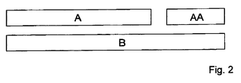
- FIG. 2 The method for operating an internal combustion engine (as shown in Fig.1 ) is illustrated by the block diagram of Fig. 2 .
- the reference numbers of Fig. 1 and Fig. 2 correspond to each other so that in the following the reference numbers shown in Fig. 1 are used for the description of Fig. 2 .
- Step A relates to the injection of fuel in the pre-chamber 41.
- the step of injecting fuel is carried out by injecting fuel in the pre-chamber 41 only.
- the step of injecting fuel in the pre-chamber 41 can comprise multiple injections (Step A, Step A, Step A, ...) of fuel via fuel injector 43 in the pre-chamber 41.
- step B the injected fuel in the pre-chamber 41 is ignited via the igniter portion 43 for pre-heating of the pre-chamber 41 (volume) prior to injecting fuel via direct injector 6 in the main combustion chamber 21 for combusting the injected fuel in the main combustion chamber 21.
- Step B for timing the ignition (Step B) in a manner to ignite at evenly rich mixtures in the pre-chamber 41, the step of igniting the injected fuel (Step B) is carried out in between of an identical number of subsequent injections of the multiple injections (Step A, Step A, Step B, Step A, Step A, Step B, ...) of fuel in the pre-chamber 41.
- the injection of fuel in the pre-chamber 41 (Step A) and the ignition of the injected fuel (Step B) are carried out after a predetermined time duration t starting from the injection of fuel.
- the injection of fuel in the pre-chamber 41 and the ignition of the injected fuel are carried out after a predetermined angular movement of rotating engine components (e.g. crank shaft 5).
- Step AA relates to that according to an alternative, the step of injecting fuel in the pre-chamber 41 and injecting fuel in the main combustion chamber 21 via direct injector 6 are carried out simultaneously. This allows improved control of the mixture in the main combustion chamber 21 and the pre-chamber.
- the mixture in the pre-chamber 41 is preferably rich with A less than 1.
- the mixture in the main combustion chamber 21 is chosen to be ultra lean with A more than 1.6 and in particular in the range of ⁇ in between of 1.6 to 2.3.
Abstract
- providing an internal combustion engine 1 having at least one cylinder 2 and a piston 3 supported at a crankshaft 5 for repeated reciprocal movement in the cylinder 2 so as to define a main combustion chamber 21, the internal combustion engine 1 further having an ignition device 4 arranged in said cylinder 2 with an igniter portion 42 and a fuel injector 43 which are both arranged at a pre-chamber 41, wherein the pre-chamber 41 has a plurality of orifices 44 for providing fluid communication between said pre-chamber 41 and the main combustion chamber 21;
- injecting fuel in the pre-chamber 41; and
- igniting the injected fuel in the pre-chamber 41 for pre-heating of the pre-chamber 41 prior to injecting fuel in the main combustion chamber 21 for combusting the injected fuel in the main combustion chamber 21.
Description
- The present invention relates to a method for starting an internal combustion engine according to the independent claim.
- The invention is from the technical field of internal combustion engines having a pre-chamber for the ignition of the combustion chamber by use of turbulent jet ignition and relates in particular to cold start strategies therefore.
- A prior art internal combustion engine employing an ignition system for turbulent jet ignition is disclosed in
US 2012 103 302 A1 . The internal combustion engine has an engine block with cylinders. Each cylinder has a cylinder head bordering a main combustion chamber in which the main air fuel charge is ignited. A piston is arranged bordering the combustion chamber which is connected via a rod at a crankshaft so as to allow a reciprocal movement. Each cylinder head defines an intake opening and an exhaust opening. The intake and exhaust openings are opened and closed via cam driven valves to provide fluid communication between the cylinder and an intake manifold and an exhaust manifold. The internal combustion engine also includes a fuel injector mounted in the intake manifold as a means of introducing the main fuel/air charge into the combustion chamber through the intake port. The ignition device has an igniter portion and an injector arranged to face an inner pre-chamber volume. - The pre-chamber is shaped so as to form a nozzle having a plurality of orifices disposed spaced from one another and providing fluid communication between the pre-chamber and the combustion chamber. The igniter portion ignites the fuel in the pre-chamber. The orifice diameter is kept small to promote flame quenching as the combustion products exit out of the pre-chamber into the main combustion chamber. Flame quenching means that the partially combusted pre-chamber products are forced through the small orifices of the pre-chamber. The combustion products are extinguished but dispersed through the main combustion chamber then react with the main fuel charge and initiates combustion in the main fuel chamber at multiple locations through chemical, thermal and turbulent effects some distance away from the pre-chamber nozzle.
- An improved ignition device capable of creating a more efficient reactive jet is disclosed in
US 2015 006 848 9 A1 . The pre-chamber of this ignition device includes a plurality of orifices of an advantageous design (i.e. diameter size) to provide a fluid communication between the pre-chamber volume and the main chamber volume. - The mentioned techniques handling of low ignition qualities of mixtures of ultra-lean air-fuel ratios in internal combustion engines because of turbulent jet ignition (TJI) is a high energy ignition source.
- Lambda (λ) is a fuel-agnostic mass ratio of air to fuel present in a combustion chamber (air-fuel ratio / stoichiometric air-fuel ratio). When exactly enough air is provided to completely burn all of the fuel the ratio is stoichiometric and λ is equal 1, and ratios lower than stoichiometric are considered "rich" (A <1) while ratios higher than stoichiometric are called "lean" (λ>1). The present invention distinguishes between the λ in the pre-chamber and in the main combustion chamber.
- Conventionally the range of A > 1.6 is an ultra-lean air-fuel ratio. Ultra-lean combustion with λ > 1.6 has demonstrated the ability to both increase net thermal efficiency and significantly reduce NOx emissions. The major limitation in ultra-lean combustion systems is the poor ignition quality of the mixture which results in a "lean limit" for values of A above which the combustion engine does not ignite.
- Turbulent jet ignition enables the engine to operate in a homogeneous ultra-lean combustion mode. This combustion mode typically refers to A values greater than 1.6. The technology described herein has been shown to enable ignition of mixtures with lambda values greater than 2.3. Traditional spark ignited engines are generally incapable of operating ultra-lean due to the limited ignition energy present in a traditional spark plug. The jet igniter enables the engine to achieve ultra-lean operation by amplifying the ignition energy of a traditional spark plug. Electrical energy from the spark plug is used to convert the small quantity of fuel and air in the pre-chamber into chemical energy via pre-chamber combustion. The resulting rise in pressure in the pre-chamber causes this chemical energy to rapidly transfer to the main combustion chamber in the form of jets formed as contents pass through the pre-chamber nozzle orifices. Spark plug ignition energy is therefore amplified and distributed in the main combustion chamber, enabling combustion of fuel-air mixtures that nominally have poor ignition quality. The claims contained herein relate to the action of starting a jet ignition engine, in particular prior to transitioning the engine to ultra-lean operation.
- A cold start strategy aims to provide methods for starting an internal combustion engine when it is cold compared to its normal operating temperature, e.g. when the engine or vehicle is started after an extended period of time during which there is no engine or vehicle operation and engine temperatures are at or near ambient environment temperatures. There are many ways to define a cold start, e.g. by a predetermined period of time after turning off the engine or by a difference in temperature compared to the normal operating temperature.
- Hence it is an object of the invention to provide method for starting an internal combustion engine which is ignited by turbulent jet ignition so that it can quickly transition to operate at lean and ultra-lean air-fuel mixtures and rapidly input heat into the exhaust catalysts to activate said catalysts. The methods described herein pertain to all definitions of engine "cold start".
- This object is achieved by a method for starting an internal combustion engine comprising the steps of: Firstly, provide an internal combustion engine having at least one cylinder and a piston supported at a crankshaft for repeated reciprocal movement in the cylinder so as to define a combustion chamber. The internal combustion engine has an ignition device arranged in said cylinder with an igniter portion and a fuel injector which are both arranged at a pre-chamber. The pre-chamber has a plurality of orifices for providing fluid communication between said pre-chamber and the combustion chamber. Secondly, inject fuel in the pre-chamber. Thirdly, ignite the injected fuel in the pre-chamber for pre-heating of the pre-chamber volume and surfaces prior to injecting fuel in the main combustion chamber for combusting the injected fuel in the main combustion chamber.
- This method allows for igniting the air-fuel ratio with a low flammability during cold starts in particular when the density of air is high because of the cool temperatures. By pre-heating of the pre-chamber, the starting of the internal combustion engine which is ignited by turbulent jet ignition is improved so that the air-fuel mixtures can be ignited in conditions when the engine is cold compared to the normal operating temperature. The pre-heating of the pre-chamber allows quick production of stable, repeatable combustion within a low number of engine revolutions and, hence, is capable of reducing tailpipe emissions through a rapid increase in exhaust gas temperature which is required for thermal activation of exhaust catalysts to catalyze and/or to capture exhaust products for reducing exhaust emissions.
- Specifically, the step of injecting fuel comprises injecting fuel in the pre-chamber only. That means that the fuel injection can be carried out by the fuel injector in the pre-chamber, while the fuel injector for fueling the main combustion chamber does not operate. This allows for separately controlling the mixture in the pre-chamber.
- According to an advantageous aspect, the step of injecting fuel in the pre-chamber (only) comprises multiple injections of fuel via fuel injector in the pre-chamber. This allows for adding more fuel and, hence, to provide a rich mixture to be ignited in the pre-chamber which improves flammability of the fuel-air mixture.
- It is particularly preferred, when the ignition of injected fuel is carried out in between of each of two subsequent injections of the multiple injections of fuel in the pre-chamber. This kind of operation allows for multiple ignition events at rich pre-chamber mixture conditions.
- Preferably, the step of igniting the injected fuel is carried out in between of an identical number of subsequent injections of the multiple injections of fuel in the pre-chamber. This aspect allows for timing the ignition in a manner to ignite at evenly rich mixtures in the pre-chamber (e.g. when the mixture in the pre-chamber at two injections is lean compared to at three injections).
- According to another aspect, the injection of fuel in the pre-chamber and the ignition of the injected fuel are carried out after a predetermined time duration T starting from the injection of fuel. This allows for igniting the injected fuel independent from a angular position of the rotating engine components (e.g. crank shaft), i.e. on a time-based schedule, whereby the relative timing of injection of fuel in the pre-chamber and the spark event are specified based on time duration T.
- An alternative aspect relates to that the injection of fuel in the pre-chamber and the ignition of the injected fuel are carried out after a predetermined angular movement of rotating engine components (e.g. crank shaft). This allows for igniting the injected fuel in the pre-chamber without the need for a time based control unit and the operation can be controlled on a rotating angular position-based schedule, i.e. relative timing of injection of fuel in the pre-chamber and the spark event are specified based on angular position of rotating engine components.
- According to another preferred aspect, the injection of fuel in the pre-chamber and the ignition of the injected fuel are carried out prior to a compression move of the piston in the cylinder. This aspect allows for a fast cold start operation, in which the pre-chamber volume and surfaces are pre-heated prior to the first compression and subsequent ignition in the main combustion chamber.
- Advantageously, the injection of fuel in the pre-chamber and the ignition of the injected fuel are carried out at different individual angular positions of the rotating engine components (e.g. crankshaft) for a predetermined time interval t. This allows for controlling the pre-chamber mixture based on the chosen time interval t.
- According to an alternative aspect, the injection of fuel in the pre-chamber and the ignition of the injected fuel are carried out at a continuous range of angular positions α of the rotating engine parts (e.g. crankshaft). This allows for controlling the pre chamber mixture based on the chosen continuous range of angular positions α of the crankshaft, i.e. the wider the range α, the richer the pre-chamber mixture is.
- It is particularly preferred that the injection of fuel in the pre-chamber and the ignition of the injected fuel are carried out prior to a movement of the rotating engine components (e.g. crankshaft). This allows carrying out the pre-heating over a comparably long period of time prior to the combustion in the main combustion chamber, what can be particularly advantageous in case of low ambient temperatures.
- According to another preferred aspect, the amount of injected fuel in the pre-chamber is chosen so that the lambda value λ is equal to 1 in the pre-chamber. Global lambda in the pre-chamber subsequent to the fuel injection event in the pre-chamber can be approximated according to the following equation:

- AFR = air-fuel ratio
- vol = pre-chamber volume
- Another preferred aspect relates to that the amount of injected fuel in the pre-chamber is chosen so that A is less than 1. A rich mixture is regarded to provide enhanced flammability of the mixture in the pre-chamber.
- The invention relates according to an alternative to that the fuel is injected in the pre-chamber only to that the method further comprises the step of injecting fuel in the pre-chamber and simultaneously injecting fuel in the main combustion chamber. This allows improved simultaneous controlling of the mixture in the main combustion chamber. This can be carried out by a direct injector provided in a manner facing the main combustion chamber or the inlet channel which can be opened towards the main combustion chamber via an inlet valve.
- It is particularly preferred, if the amount of injected fuel in the main combustion chamber is chosen so that A is less than 1.6 in the main combustion chamber. This lean mixture is comparably rich to the nominal ultra-lean mixtures. The mixture can be changed to ultra lean after the cold start strategy disclosed herein has been carried out and stable combustion is achieved.
- A particularly preferred aspect relates to that the amount of injected fuel in main combustion chamber is chosen so that A is less than 1 in the main combustion chamber. This mixture is rich compared to an overall standard combustion engine operation and can advantageous if the engine is operated in a cold environment.
- The advantages of the invention are described in the following in connection to the drawings. In the following:
-
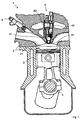
Fig. 1 is a vertical cross-section of an internal combustion engine having an ignition device for turbulent jet ignition; and -
Fig. 2 is a block diagram describing the steps of a method for operating an internal combustion engine. - In
Fig. 1 , an example forinternal combustion engine 1 is given which shows in the present illustration onecylinder 2 and apiston 3 supported at acrankshaft 5 for repeated reciprocal movement in thecylinder 2.Cylinder 2 anpiston 3 define amain combustion chamber 21.Internal combustion engine 1 has anignition device 4 arranged to face thecombustion chamber 21.Ignition device 4 has anigniter portion 42 and afuel injector 43 which are both arranged at a pre-chamber 41 so as to form a part of the inner volume of the pre-chamber 41. The pre-chamber 41 has a plurality oforifices 44 for providing fluid communication between the inner volume ofpre-chamber 41 and the inner volume ofmain combustion chamber 21. - According to the invention, the fuel is injected in
pre-chamber 41, which can be achieved by use offuel injector 43. Subsequently, the injected fuel is ignited in the pre-chamber 41 via theigniter portion 42. The generated combustion heat allows for pre-heating of the pre-chamber 41. The pre-heating is carried out prior to injecting fuel viadirect injector 6 in themain combustion chamber 21 for combusting the injected fuel in themain combustion chamber 21. - During cold starts in particular when fuel-air mixtures and combustion chamber surfaces are cold, causing a high degree of heat transfer thereby inhibiting complete combustion kinetrics, by pre-heating of the pre-chamber 41, the starting of the
internal combustion engine 1 which is ignited by turbulent jet ignition is improved, in particular at or prior to operation with ultra-lean air-fuel mixtures. The pre-heating of the pre-chamber 41 allows quickly producing a stable, repeatable combustion within a low number of crankshaft 5 revolutions and, hence, is capable of reducing tailpipe emissions through a rapid increase in exhaust gas temperature which is required for thermal activation of exhaust catalysts to capture/catalyze exhaust products for reducing the emission. - The method for operating an internal combustion engine (as shown in
Fig.1 ) is illustrated by the block diagram ofFig. 2 . The reference numbers ofFig. 1 andFig. 2 correspond to each other so that in the following the reference numbers shown inFig. 1 are used for the description ofFig. 2 . - Step A relates to the injection of fuel in the pre-chamber 41. Preferably, the step of injecting fuel is carried out by injecting fuel in the pre-chamber 41 only. In the present example, the step of injecting fuel in the pre-chamber 41 can comprise multiple injections (Step A, Step A, Step A, ...) of fuel via
fuel injector 43 in the pre-chamber 41. - In the step B the injected fuel in the pre-chamber 41 is ignited via the
igniter portion 43 for pre-heating of the pre-chamber 41 (volume) prior to injecting fuel viadirect injector 6 in themain combustion chamber 21 for combusting the injected fuel in themain combustion chamber 21. - In case of multiple fuel injections (Step A, Step A, Step A, ...), for timing the ignition (Step B) in a manner to ignite at evenly rich mixtures in the pre-chamber 41, the step of igniting the injected fuel (Step B) is carried out in between of an identical number of subsequent injections of the multiple injections (Step A, Step A, Step B, Step A, Step A, Step B, ...) of fuel in the pre-chamber 41.
- To allow for the operation on a time-based schedule, whereby the relative timing of injection of fuel in the pre-chamber 41 and the spark event are specified based on time duration t, the injection of fuel in the pre-chamber 41 (Step A) and the ignition of the injected fuel (Step B) are carried out after a predetermined time duration t starting from the injection of fuel. As an alternative thereto, the injection of fuel in the pre-chamber 41 and the ignition of the injected fuel are carried out after a predetermined angular movement of rotating engine components (e.g. crank shaft 5).
- Step AA relates to that according to an alternative, the step of injecting fuel in the pre-chamber 41 and injecting fuel in the
main combustion chamber 21 viadirect injector 6 are carried out simultaneously. This allows improved control of the mixture in themain combustion chamber 21 and the pre-chamber.
During the cold start operation, the mixture in the pre-chamber 41 is preferably rich with A less than 1. After the cold start has been carried out, the mixture in themain combustion chamber 21 is chosen to be ultra lean with A more than 1.6 and in particular in the range of λ in between of 1.6 to 2.3.
Claims (15)
- Method for starting an internal combustion engine (1) comprising the steps of:- providing an internal combustion engine (1) having at least one cylinder (2) and a piston (3) supported at a crankshaft (5) for repeated reciprocal movement in the cylinder (2) so as to define a main combustion chamber (21), the internal combustion engine (1) further having an ignition device (4) arranged in said cylinder (2) with an igniter portion (42) and a fuel injector (43) which are both arranged at a pre-chamber (41), wherein the pre-chamber (41) has a plurality of orifices (44) for providing fluid communication between said pre-chamber (41) and the main combustion chamber (21);- injecting fuel in the pre-chamber (41); and- igniting the injected fuel in the pre-chamber (41) for pre-heating of the pre-chamber (41) prior to injecting fuel in the main combustion chamber (21) for combusting the injected fuel in the main combustion chamber (21).
- Method according to claim 1, wherein the step of injecting fuel comprises injecting fuel in the pre-chamber (41) only.
- Method according to claim 2, wherein the step of injecting fuel in the pre-chamber (41) comprises multiple injections of fuel via fuel injector (43) in the pre-chamber (41).
- Method according to claim 2, wherein the step of igniting the injected fuel is carried out in between of an identical number of subsequent injections of the multiple injections of fuel in the pre-chamber (41).
- Method according to any one of the preceding claims, wherein the injection of fuel in the pre-chamber (41) and the ignition of the injected fuel are carried out after a predetermined time duration T starting from the injection of fuel.
- Method according to any one of claims 1 to 4, wherein the injection of fuel in the pre-chamber (41) and the ignition of the injected fuel are carried out after a predetermined angular movement of rotating engine components.
- Method according to any one of claims 1 to 4, wherein the injection of fuel in the pre-chamber (41) and the ignition of the injected fuel are carried out prior to a compression move of the piston (3) in the cylinder (21).
- Method according to any one of the preceding claims, wherein the injection of fuel in the pre-chamber (41) and the ignition of the injected fuel are carried out at different individual angular positions of the rotating engine components (2) for a predetermined time interval t.
- Method according to any one of claims 1 to 7, wherein the injection of fuel in the pre-chamber (41) and the ignition of the injected fuel is carried out at a continuous range of angular positions α of the crankshaft (2).
- Method according to any one of claims 1 to 5, wherein the injection of fuel in the pre-chamber (41) and the ignition of the injected fuel are carried out prior to a movement of the crankshaft (5).
- Method according to any one of the preceding claims, wherein the amount of injected fuel in the pre-chamber (41) is chosen so that the lambda value A is equal to 1 in the pre-chamber (41).
- Method according to claim 1 to 10, wherein the amount of injected fuel in the pre-chamber (41) is chosen so that the air/fuel ratio λ is less than 1.
- Method according to claim 1, further comprising the step of injecting fuel in the pre-chamber (41) comprises the step of simultaneously injecting fuel in the main combustion chamber (21).
- Method according to claim 13, wherein the amount of injected fuel in the main combustion chamber (21) is chosen so that the air/fuel ratio A is less than 1.6 in the main combustion chamber (21).
- Method according to claim 13, wherein the amount of injected fuel in the main combustion chamber (21) is chosen so that the air/fuel ratio A is less than 1 in the main combustion chamber (21).
Priority Applications (5)
| Application Number | Priority Date | Filing Date | Title |
|---|---|---|---|
| EP16001518.6A EP3267008A1 (en) | 2016-07-06 | 2016-07-06 | Method for starting an internal combustion engine |
| JP2017010883A JP2018003831A (en) | 2016-07-06 | 2017-01-25 | Internal combustion engine starting method |
| KR1020170022204A KR101942876B1 (en) | 2016-07-06 | 2017-02-20 | Method for starting an internal combustion engine |
| US15/437,950 US10400696B2 (en) | 2016-07-06 | 2017-02-21 | Method for starting an internal combustion engine |
| CN201710097452.XA CN107587930B (en) | 2016-07-06 | 2017-02-22 | Method for starting an internal combustion engine |
Applications Claiming Priority (1)
| Application Number | Priority Date | Filing Date | Title |
|---|---|---|---|
| EP16001518.6A EP3267008A1 (en) | 2016-07-06 | 2016-07-06 | Method for starting an internal combustion engine |
Publications (1)
| Publication Number | Publication Date |
|---|---|
| EP3267008A1 true EP3267008A1 (en) | 2018-01-10 |
Family
ID=56411359
Family Applications (1)
| Application Number | Title | Priority Date | Filing Date |
|---|---|---|---|
| EP16001518.6A Pending EP3267008A1 (en) | 2016-07-06 | 2016-07-06 | Method for starting an internal combustion engine |
Country Status (5)
| Country | Link |
|---|---|
| US (1) | US10400696B2 (en) |
| EP (1) | EP3267008A1 (en) |
| JP (1) | JP2018003831A (en) |
| KR (1) | KR101942876B1 (en) |
| CN (1) | CN107587930B (en) |
Families Citing this family (22)
| Publication number | Priority date | Publication date | Assignee | Title |
|---|---|---|---|---|
| US10837355B2 (en) * | 2017-12-28 | 2020-11-17 | Honda Motor Co., Ltd. | Internal combustion engine |
| CN109098834B (en) | 2018-09-20 | 2020-07-24 | 天津大学 | Engine combustion system with multiple combustion modes |
| DE102019201344A1 (en) * | 2019-02-01 | 2020-08-06 | Hitachi Automotive Systems, Ltd. | Device and method for controlling the start of an internal combustion engine |
| CN110094257A (en) * | 2019-04-30 | 2019-08-06 | 天津大学 | The precombustion chamber jet flame ignition combustion system of piston type Heavy End Aviation Fuel engine |
| DE102019208930A1 (en) * | 2019-06-19 | 2020-12-24 | Hitachi Automotive Systems, Ltd. | DEVICE AND METHOD OF CONTROLLING A TEMPERATURE OF AN ANALYTIC CHAMBER INCLUDED IN AN IGNITION DEVICE OF AN INTERNAL COMBUSTION MACHINE |
| CN110725765B (en) * | 2019-07-15 | 2022-02-11 | 天津大学 | Jet igniter of water-cooled engine |
| CN110925077B (en) * | 2019-11-18 | 2021-03-26 | 清华大学 | Compression-ignition jet ignition combustion system and combustion control method |
| US11703006B2 (en) | 2019-11-26 | 2023-07-18 | Ford Global Technologies, Llc | Systems and methods for diagnosing air and fuel offsets in a prechamber |
| US10989129B1 (en) | 2019-12-18 | 2021-04-27 | Ford Global Technologies, Llc | Systems and methods for adjusting fueling in a cylinder with a pre-chamber |
| DE102019008816A1 (en) * | 2019-12-18 | 2021-06-24 | Daimler Ag | Method for starting an internal combustion engine of a motor vehicle, in particular a motor vehicle |
| US11408329B2 (en) * | 2019-12-19 | 2022-08-09 | Board Of Trustees Of Michigan State University | Engine turbulent jet ignition system |
| DE102020101552A1 (en) | 2020-01-23 | 2021-07-29 | Bayerische Motoren Werke Aktiengesellschaft | Method for operating an externally ignited reciprocating internal combustion engine |
| US10947948B1 (en) | 2020-02-12 | 2021-03-16 | Ford Global Technologies, Llc | Systems and methods for ignition coil multiplexing in a pre-chamber system |
| US11118497B2 (en) | 2020-02-12 | 2021-09-14 | Ford Global Technologies, Llc | Systems and methods for fouling reduction in a pre-chamber |
| US20210260626A1 (en) | 2020-02-26 | 2021-08-26 | InTunes Products, LLC | Package handling and sorting system |
| US11255284B2 (en) * | 2020-02-26 | 2022-02-22 | Ford Global Technologies, Llc | Systems and methods for catalyst heating during cold-start with an active pre-chamber |
| US11085402B1 (en) | 2020-04-01 | 2021-08-10 | Ford Global Technologies, Llc | Methods and systems for operating an adjustable pre-chamber |
| US11073097B1 (en) | 2020-07-06 | 2021-07-27 | Ford Global Technologies, Llc | Methods and system for cold starting an engine |
| CN111894726A (en) * | 2020-08-11 | 2020-11-06 | 天津大学 | Diesel engine cold-start jet flow flame auxiliary ignition device and control method thereof |
| EP3981978A1 (en) * | 2020-10-09 | 2022-04-13 | MAHLE Powertrain, LLC | Method for operating a hydrogen fuelled combustion engine |
| JP7150095B1 (en) * | 2021-05-17 | 2022-10-07 | 三菱電機株式会社 | CONTROL DEVICE AND CONTROL METHOD FOR INTERNAL COMBUSTION ENGINE |
| US11603818B1 (en) * | 2021-10-07 | 2023-03-14 | Ford Global Technologies, Llc | Methods and system for preparing an engine for starting |
Citations (8)
| Publication number | Priority date | Publication date | Assignee | Title |
|---|---|---|---|---|
| US5090378A (en) * | 1991-02-22 | 1992-02-25 | The Cessna Aircraft Company | Dual nozzle single pump fuel injection system |
| EP0957246A2 (en) * | 1998-05-14 | 1999-11-17 | Niigata Engineering Co., Ltd. | Lean combustion gas engine |
| US20090241896A1 (en) * | 2008-03-31 | 2009-10-01 | Caterpillar Inc. | Ignition system utilizing igniter and gas injector |
| US20120103302A1 (en) | 2010-11-01 | 2012-05-03 | William Attard | Turbulent jet ignition pre-chamber combustion system for spark ignition engines |
| WO2013175530A1 (en) * | 2012-05-23 | 2013-11-28 | 川崎重工業株式会社 | Device and method for adjusting fuel for gas engines |
| US20140209057A1 (en) * | 2013-01-28 | 2014-07-31 | Sonex Research, Inc. | Method for modifying combustion chamber in a reciprocating piston internal combustion engine and resulting engine |
| US20150068489A1 (en) | 2010-11-01 | 2015-03-12 | Mahle Powertrain, Llc | Turbulent jet ignition pre-chamber combustion system for spark ignition engines |
| WO2015138987A1 (en) * | 2014-03-14 | 2015-09-17 | Advanced Green Technologies, Llc | Pre-chamber injector-igniter for gaseous fuel combustion and associated systems and methods |
Family Cites Families (16)
| Publication number | Priority date | Publication date | Assignee | Title |
|---|---|---|---|---|
| JPS5450712A (en) * | 1977-09-29 | 1979-04-20 | Honda Motor Co Ltd | Combustion chamber of engine |
| JPS6045716A (en) * | 1984-07-25 | 1985-03-12 | Nissan Motor Co Ltd | Internal-combustion engine |
| FI121759B (en) * | 2007-11-09 | 2011-03-31 | Waertsilae Finland Oy | Internal combustion engine pre-chamber arrangement |
| JP4599390B2 (en) * | 2007-12-14 | 2010-12-15 | 三菱重工業株式会社 | Micro pilot injection gas engine |
| US8882863B2 (en) * | 2008-05-14 | 2014-11-11 | Alliant Techsystems Inc. | Fuel reformulation systems |
| JP2010196517A (en) * | 2009-02-24 | 2010-09-09 | Nissan Motor Co Ltd | Control device for internal combustion engine |
| JP5357957B2 (en) * | 2009-02-27 | 2013-12-04 | 三菱重工業株式会社 | Control method for sub-chamber gas engine |
| JP2011236789A (en) * | 2010-05-10 | 2011-11-24 | Toyota Industries Corp | Fuel supply device |
| JP5826095B2 (en) * | 2012-03-30 | 2015-12-02 | 大阪瓦斯株式会社 | Sub-chamber gas engine operating method and sub-chamber gas engine |
| US10161296B2 (en) * | 2012-11-27 | 2018-12-25 | Board Of Trustees Of Michigan State University | Internal combustion engine |
| JP5928354B2 (en) * | 2013-01-23 | 2016-06-01 | マツダ株式会社 | Spark ignition multi-cylinder engine starter |
| EP2948657A1 (en) * | 2013-01-28 | 2015-12-02 | Sonex Research Inc. | Thermally stratified regenerative combustion chamber and method for modifying a combustion chamber in an internal combustion engine and resulting engine |
| CN106194395A (en) * | 2014-09-25 | 2016-12-07 | 马勒动力总成有限公司 | The turbulent jet igniting precombustion chamber combustion system of spark ignition engine |
| AT516250B1 (en) * | 2015-01-07 | 2016-04-15 | Hoerbiger Kompressortech Hold | Fuel gas supply and ignition device for a gas engine |
| AT516251B1 (en) * | 2015-01-07 | 2016-04-15 | Hoerbiger Kompressortech Hold | Fuel gas supply and ignition device for a gas engine |
| US9890689B2 (en) * | 2015-10-29 | 2018-02-13 | Woodward, Inc. | Gaseous fuel combustion |
-
2016
- 2016-07-06 EP EP16001518.6A patent/EP3267008A1/en active Pending
-
2017
- 2017-01-25 JP JP2017010883A patent/JP2018003831A/en active Pending
- 2017-02-20 KR KR1020170022204A patent/KR101942876B1/en active IP Right Grant
- 2017-02-21 US US15/437,950 patent/US10400696B2/en active Active
- 2017-02-22 CN CN201710097452.XA patent/CN107587930B/en active Active
Patent Citations (8)
| Publication number | Priority date | Publication date | Assignee | Title |
|---|---|---|---|---|
| US5090378A (en) * | 1991-02-22 | 1992-02-25 | The Cessna Aircraft Company | Dual nozzle single pump fuel injection system |
| EP0957246A2 (en) * | 1998-05-14 | 1999-11-17 | Niigata Engineering Co., Ltd. | Lean combustion gas engine |
| US20090241896A1 (en) * | 2008-03-31 | 2009-10-01 | Caterpillar Inc. | Ignition system utilizing igniter and gas injector |
| US20120103302A1 (en) | 2010-11-01 | 2012-05-03 | William Attard | Turbulent jet ignition pre-chamber combustion system for spark ignition engines |
| US20150068489A1 (en) | 2010-11-01 | 2015-03-12 | Mahle Powertrain, Llc | Turbulent jet ignition pre-chamber combustion system for spark ignition engines |
| WO2013175530A1 (en) * | 2012-05-23 | 2013-11-28 | 川崎重工業株式会社 | Device and method for adjusting fuel for gas engines |
| US20140209057A1 (en) * | 2013-01-28 | 2014-07-31 | Sonex Research, Inc. | Method for modifying combustion chamber in a reciprocating piston internal combustion engine and resulting engine |
| WO2015138987A1 (en) * | 2014-03-14 | 2015-09-17 | Advanced Green Technologies, Llc | Pre-chamber injector-igniter for gaseous fuel combustion and associated systems and methods |
Also Published As
| Publication number | Publication date |
|---|---|
| US20180010536A1 (en) | 2018-01-11 |
| CN107587930B (en) | 2020-11-24 |
| CN107587930A (en) | 2018-01-16 |
| KR20180005591A (en) | 2018-01-16 |
| US10400696B2 (en) | 2019-09-03 |
| KR101942876B1 (en) | 2019-01-28 |
| JP2018003831A (en) | 2018-01-11 |
Similar Documents
| Publication | Publication Date | Title |
|---|---|---|
| US10400696B2 (en) | Method for starting an internal combustion engine | |
| US10400706B2 (en) | Control apparatus for internal combustion engine | |
| US7073479B2 (en) | Method for operating an internal combustion engine with direct fuel injection | |
| JP4689723B2 (en) | Method for cold operation of a spark ignition internal combustion engine | |
| EP3001008B1 (en) | Turbulent jet ingnition pre-chamber combustion system for spark ignition engines | |
| US9784207B2 (en) | Control apparatus for internal combustion engine | |
| WO2012061397A2 (en) | Turbulent jet ignition pre-chamber combustion system for spark ignition engines | |
| EP3981978A1 (en) | Method for operating a hydrogen fuelled combustion engine | |
| US10066574B2 (en) | Control apparatus for internal combustion engine | |
| JP2016000969A5 (en) | ||
| JP7430805B2 (en) | How to operate a motor vehicle, especially an automobile internal combustion engine | |
| US6595181B2 (en) | Dual mode engine combustion process | |
| US20170241368A1 (en) | Ducted combustion system | |
| KR20120058502A (en) | Method for operating an internal combustion engine | |
| JP2016089747A (en) | Control device of internal combustion engine | |
| US7487756B2 (en) | Direct fuel injection-type spark ignition internal combustion engine | |
| US4126106A (en) | Mixed cycle internal combustion engine | |
| JP2009500560A (en) | Internal combustion engine operation method | |
| US5477822A (en) | Spark ignition engine with cylinder head combustion chamber | |
| Murase et al. | Ignition timing control of homogeneous charge compression ignition engines by pulsed flame jets | |
| EP3037646B1 (en) | Method for operating internal combustion engines | |
| US11739702B2 (en) | Reheated residual gas ignitor | |
| JP2022051346A (en) | Internal combustion engine | |
| JP2018105162A (en) | Internal combustion engine control device | |
| KR20060030602A (en) | Injector nozzle of diesel engine |
Legal Events
| Date | Code | Title | Description |
|---|---|---|---|
| PUAI | Public reference made under article 153(3) epc to a published international application that has entered the european phase |
Free format text: ORIGINAL CODE: 0009012 |
|
| STAA | Information on the status of an ep patent application or granted ep patent |
Free format text: STATUS: THE APPLICATION HAS BEEN PUBLISHED |
|
| AK | Designated contracting states |
Kind code of ref document: A1 Designated state(s): AL AT BE BG CH CY CZ DE DK EE ES FI FR GB GR HR HU IE IS IT LI LT LU LV MC MK MT NL NO PL PT RO RS SE SI SK SM TR |
|
| AX | Request for extension of the european patent |
Extension state: BA ME |
|
| STAA | Information on the status of an ep patent application or granted ep patent |
Free format text: STATUS: REQUEST FOR EXAMINATION WAS MADE |
|
| 17P | Request for examination filed |
Effective date: 20180705 |
|
| RBV | Designated contracting states (corrected) |
Designated state(s): AL AT BE BG CH CY CZ DE DK EE ES FI FR GB GR HR HU IE IS IT LI LT LU LV MC MK MT NL NO PL PT RO RS SE SI SK SM TR |
|
| STAA | Information on the status of an ep patent application or granted ep patent |
Free format text: STATUS: EXAMINATION IS IN PROGRESS |
|
| 17Q | First examination report despatched |
Effective date: 20181205 |
|
| STAA | Information on the status of an ep patent application or granted ep patent |
Free format text: STATUS: EXAMINATION IS IN PROGRESS |
|
| STAA | Information on the status of an ep patent application or granted ep patent |
Free format text: STATUS: EXAMINATION IS IN PROGRESS |