EP3266906A1 - Method for carrying out continuous electrolytic etching on oriented magnetic steel strip, and apparatus for carrying out continuous electrolytic etching on oriented magnetic steel strip - Google Patents
Method for carrying out continuous electrolytic etching on oriented magnetic steel strip, and apparatus for carrying out continuous electrolytic etching on oriented magnetic steel strip Download PDFInfo
- Publication number
- EP3266906A1 EP3266906A1 EP16758717.9A EP16758717A EP3266906A1 EP 3266906 A1 EP3266906 A1 EP 3266906A1 EP 16758717 A EP16758717 A EP 16758717A EP 3266906 A1 EP3266906 A1 EP 3266906A1
- Authority
- EP
- European Patent Office
- Prior art keywords
- steel strip
- oriented electrical
- electrical steel
- grain oriented
- electrolytic etching
- Prior art date
- Legal status (The legal status is an assumption and is not a legal conclusion. Google has not performed a legal analysis and makes no representation as to the accuracy of the status listed.)
- Granted
Links
Images

Classifications
-
- C—CHEMISTRY; METALLURGY
- C25—ELECTROLYTIC OR ELECTROPHORETIC PROCESSES; APPARATUS THEREFOR
- C25F—PROCESSES FOR THE ELECTROLYTIC REMOVAL OF MATERIALS FROM OBJECTS; APPARATUS THEREFOR
- C25F3/00—Electrolytic etching or polishing
- C25F3/02—Etching
- C25F3/06—Etching of iron or steel
-
- C—CHEMISTRY; METALLURGY
- C21—METALLURGY OF IRON
- C21D—MODIFYING THE PHYSICAL STRUCTURE OF FERROUS METALS; GENERAL DEVICES FOR HEAT TREATMENT OF FERROUS OR NON-FERROUS METALS OR ALLOYS; MAKING METAL MALLEABLE, e.g. BY DECARBURISATION OR TEMPERING
- C21D8/00—Modifying the physical properties of ferrous metals or ferrous alloys by deformation combined with, or followed by, heat treatment
- C21D8/12—Modifying the physical properties of ferrous metals or ferrous alloys by deformation combined with, or followed by, heat treatment during manufacturing of articles with special electromagnetic properties
-
- C—CHEMISTRY; METALLURGY
- C21—METALLURGY OF IRON
- C21D—MODIFYING THE PHYSICAL STRUCTURE OF FERROUS METALS; GENERAL DEVICES FOR HEAT TREATMENT OF FERROUS OR NON-FERROUS METALS OR ALLOYS; MAKING METAL MALLEABLE, e.g. BY DECARBURISATION OR TEMPERING
- C21D8/00—Modifying the physical properties of ferrous metals or ferrous alloys by deformation combined with, or followed by, heat treatment
- C21D8/12—Modifying the physical properties of ferrous metals or ferrous alloys by deformation combined with, or followed by, heat treatment during manufacturing of articles with special electromagnetic properties
- C21D8/1216—Modifying the physical properties of ferrous metals or ferrous alloys by deformation combined with, or followed by, heat treatment during manufacturing of articles with special electromagnetic properties characterised by the working steps
- C21D8/1233—Cold rolling
-
- C—CHEMISTRY; METALLURGY
- C21—METALLURGY OF IRON
- C21D—MODIFYING THE PHYSICAL STRUCTURE OF FERROUS METALS; GENERAL DEVICES FOR HEAT TREATMENT OF FERROUS OR NON-FERROUS METALS OR ALLOYS; MAKING METAL MALLEABLE, e.g. BY DECARBURISATION OR TEMPERING
- C21D8/00—Modifying the physical properties of ferrous metals or ferrous alloys by deformation combined with, or followed by, heat treatment
- C21D8/12—Modifying the physical properties of ferrous metals or ferrous alloys by deformation combined with, or followed by, heat treatment during manufacturing of articles with special electromagnetic properties
- C21D8/1277—Modifying the physical properties of ferrous metals or ferrous alloys by deformation combined with, or followed by, heat treatment during manufacturing of articles with special electromagnetic properties involving a particular surface treatment
- C21D8/1283—Application of a separating or insulating coating
-
- C—CHEMISTRY; METALLURGY
- C22—METALLURGY; FERROUS OR NON-FERROUS ALLOYS; TREATMENT OF ALLOYS OR NON-FERROUS METALS
- C22C—ALLOYS
- C22C38/00—Ferrous alloys, e.g. steel alloys
-
- C—CHEMISTRY; METALLURGY
- C22—METALLURGY; FERROUS OR NON-FERROUS ALLOYS; TREATMENT OF ALLOYS OR NON-FERROUS METALS
- C22C—ALLOYS
- C22C38/00—Ferrous alloys, e.g. steel alloys
- C22C38/02—Ferrous alloys, e.g. steel alloys containing silicon
-
- C—CHEMISTRY; METALLURGY
- C25—ELECTROLYTIC OR ELECTROPHORETIC PROCESSES; APPARATUS THEREFOR
- C25F—PROCESSES FOR THE ELECTROLYTIC REMOVAL OF MATERIALS FROM OBJECTS; APPARATUS THEREFOR
- C25F3/00—Electrolytic etching or polishing
- C25F3/02—Etching
- C25F3/14—Etching locally
-
- C—CHEMISTRY; METALLURGY
- C25—ELECTROLYTIC OR ELECTROPHORETIC PROCESSES; APPARATUS THEREFOR
- C25F—PROCESSES FOR THE ELECTROLYTIC REMOVAL OF MATERIALS FROM OBJECTS; APPARATUS THEREFOR
- C25F7/00—Constructional parts, or assemblies thereof, of cells for electrolytic removal of material from objects; Servicing or operating
-
- H—ELECTRICITY
- H01—ELECTRIC ELEMENTS
- H01F—MAGNETS; INDUCTANCES; TRANSFORMERS; SELECTION OF MATERIALS FOR THEIR MAGNETIC PROPERTIES
- H01F1/00—Magnets or magnetic bodies characterised by the magnetic materials therefor; Selection of materials for their magnetic properties
- H01F1/01—Magnets or magnetic bodies characterised by the magnetic materials therefor; Selection of materials for their magnetic properties of inorganic materials
- H01F1/03—Magnets or magnetic bodies characterised by the magnetic materials therefor; Selection of materials for their magnetic properties of inorganic materials characterised by their coercivity
- H01F1/12—Magnets or magnetic bodies characterised by the magnetic materials therefor; Selection of materials for their magnetic properties of inorganic materials characterised by their coercivity of soft-magnetic materials
- H01F1/14—Magnets or magnetic bodies characterised by the magnetic materials therefor; Selection of materials for their magnetic properties of inorganic materials characterised by their coercivity of soft-magnetic materials metals or alloys
- H01F1/16—Magnets or magnetic bodies characterised by the magnetic materials therefor; Selection of materials for their magnetic properties of inorganic materials characterised by their coercivity of soft-magnetic materials metals or alloys in the form of sheets
-
- H—ELECTRICITY
- H01—ELECTRIC ELEMENTS
- H01F—MAGNETS; INDUCTANCES; TRANSFORMERS; SELECTION OF MATERIALS FOR THEIR MAGNETIC PROPERTIES
- H01F1/00—Magnets or magnetic bodies characterised by the magnetic materials therefor; Selection of materials for their magnetic properties
- H01F1/01—Magnets or magnetic bodies characterised by the magnetic materials therefor; Selection of materials for their magnetic properties of inorganic materials
- H01F1/03—Magnets or magnetic bodies characterised by the magnetic materials therefor; Selection of materials for their magnetic properties of inorganic materials characterised by their coercivity
- H01F1/12—Magnets or magnetic bodies characterised by the magnetic materials therefor; Selection of materials for their magnetic properties of inorganic materials characterised by their coercivity of soft-magnetic materials
- H01F1/14—Magnets or magnetic bodies characterised by the magnetic materials therefor; Selection of materials for their magnetic properties of inorganic materials characterised by their coercivity of soft-magnetic materials metals or alloys
- H01F1/16—Magnets or magnetic bodies characterised by the magnetic materials therefor; Selection of materials for their magnetic properties of inorganic materials characterised by their coercivity of soft-magnetic materials metals or alloys in the form of sheets
- H01F1/18—Magnets or magnetic bodies characterised by the magnetic materials therefor; Selection of materials for their magnetic properties of inorganic materials characterised by their coercivity of soft-magnetic materials metals or alloys in the form of sheets with insulating coating
-
- C—CHEMISTRY; METALLURGY
- C21—METALLURGY OF IRON
- C21D—MODIFYING THE PHYSICAL STRUCTURE OF FERROUS METALS; GENERAL DEVICES FOR HEAT TREATMENT OF FERROUS OR NON-FERROUS METALS OR ALLOYS; MAKING METAL MALLEABLE, e.g. BY DECARBURISATION OR TEMPERING
- C21D2201/00—Treatment for obtaining particular effects
- C21D2201/05—Grain orientation
Definitions
- the present invention relates to a method for continuous electrolytic etching of a grain oriented electrical steel strip and an apparatus for continuous electrolytic etching of a grain oriented electrical steel strip.
- a technology has conventionally been disclosed which improves the properties of a grain oriented electrical steel strip (hereinafter simply referred to as "steel strip” as appropriate) by printing an etch resist on a surface of the steel strip with an electrically insulating ink, and subsequently forming an etch pattern by an electrolytic etching process on the surface of the steel strip where the etch resist has been printed (refer to Patent Literature 1).
- An electrolytic etching process that is excellent in the stability of an etched state of a product has been requested to industrially perform such a technology for improving the properties of a steel strip using such an electrolytic etching process.
- Patent Literature 2 proposes a method for obtaining the capability of uniform etching in a width direction of a steel strip by covering both sides of the steel strip and restraining the flow of an electrolyte in the width direction of the steel strip to obtain a uniform cross-sectional shape of a groove in the width direction.
- An object of the present invention is to provide a method for continuous electrolytic etching of a grain oriented electrical steel strip and an apparatus for continuous electrolytic etching of a grain oriented electrical steel strip, which can restrain variations in the shapes of etched grooves along a width direction of a steel strip.
- a method for continuous electrolytic etching of a grain oriented electrical steel strip includes a mask formation step of forming an etch mask on a surface of a grain oriented electrical steel strip cold-rolled to final thickness with a linear exposed portion exposed from the etch mask; a centering step of centering the grain oriented electrical steel strip with a position sensor and a centering apparatus, which are placed immediately upstream of an electrolytic etching apparatus; and a groove formation step of performing an electrolytic etching process in which electrolytic etching is performed in the electrolytic etching apparatus to form a linear groove on the surface of the grain oriented electrical steel strip by passing electric current between a conductor roll and an electrode placed in an electrolytic bath while the grain oriented electrical steel strip is brought into contact with the conductor roll, the grain oriented electrical steel strip is immersed in the electrolytic bath and the grain oriented electrical steel strip is facing the electrode.
- the groove formation step includes performing the electrolytic etching process using the electrode whose width is within +10 mm of a steel strip width of the grain oriented electrical steel strip.
- the groove formation step includes performing the electrolytic etching process using the electrode whose side surface in the width direction is covered with an insulating material.
- An apparatus for continuous electrolytic etching of a grain oriented electrical steel strip includes a mask-forming apparatus configured to form an etch mask on a surface of a grain oriented electrical steel strip cold-rolled to final thickness with a linear exposed portion being exposed from the etch mask; an electrolytic etching apparatus including an electrolytic bath, an electrode placed in the electrolytic bath, and a conductor roll, the electrolytic etching apparatus performing an electrolytic etching process in which electrolytic etching is performed to form a linear groove on the surface of the grain oriented electrical steel strip by passing electric current between the conductor roll and the electrode while the grain oriented electrical steel strip is brought into contact with the conductor roll, the grain oriented electrical steel strip is immersed in the electrolytic bath, and the grain oriented electrical steel strip is facing the electrode; a position sensor, placed immediately upstream of the electrolytic etching apparatus, to detect a position of the grain oriented electrical steel strip in a width direction; and a centering apparatus, placed immediately upstream of the electrolytic etching apparatus
- a method for continuous electrolytic etching of a grain oriented electrical steel strip and an apparatus for continuous electrolytic etching of a grain oriented electrical steel strip according to the present invention can suppress variations in the shapes of etched grooves in a width direction of a steel strip.
- a method for continuous electrolytic etching of a grain oriented electrical steel strip and an apparatus for continuous electrolytic etching of a grain oriented electrical steel strip according to an embodiment of the present invention are described in detail hereinafter with reference to the drawings.
- the invention is not limited by the embodiment.
- components in the following embodiment include those that are easily conceivable by a person skilled in the art, or substantially the same ones.
- the embodiment is described with reference to FIGS. 1 to 5 .
- the embodiment relates to a method for continuous electrolytic etching of a grain oriented electrical steel strip and an apparatus for continuous electrolytic etching of a grain oriented electrical steel strip.
- the method for continuous electrolytic etching of a grain oriented electrical steel strip of the embodiment forms linear grooves on a surface of a grain oriented electrical steel strip cold-rolled to final thickness by, for example, selectively forming an etch mask on the surface of the grain oriented electrical steel strip, continuously loading the grain oriented electrical steel strip into an electrolytic cell, and performing an electrolytic etching process thereon.
- FIG. 1 is a schematic configuration diagram of the apparatus for continuous electrolytic etching of a grain oriented electrical steel strip according to the embodiment of the present invention.
- an apparatus 100 for continuous electrolytic etching of a grain oriented electrical steel strip according to the embodiment includes an etch-resist-coating apparatus 2, a drying-and-baking apparatus 3, an electrolytic etching apparatus 4, an etch-resist-removing apparatus 5, a water rinse tank 6, a rinse tank 7, a centering apparatus 8, and a position sensor 9.
- the method for continuous electrolytic etching of the embodiment which is implemented by the continuous electrolytic etching apparatus 100, includes a mask formation step, a centering step, and a groove formation step.
- the mask formation step is the step of forming an etch mask 1a on a surface 11 of a grain oriented electrical steel strip 1 cold-rolled to final thickness with linear exposed portions 1b being exposed from the etch mask 1a (refer to FIG. 2 ).
- the continuous electrolytic etching apparatus 100 includes the etch-resist-coating apparatus 2 and the drying-and-baking apparatus 3 as a mask-forming apparatus.
- the etch-resist-coating apparatus 2 and the drying-and-baking apparatus 3 execute the mask formation step.
- the continuous electrolytic etching apparatus 100 coats, with an etch resist, the surface 11 of the grain oriented electrical steel strip 1 cold-rolled to final thickness, dries and bakes the grain oriented electrical steel strip 1, and selectively forms the etch mask 1a.
- the centering step is the step of centering the grain oriented electrical steel strip 1 with the position sensor 9 and the centering apparatus 8, which are placed immediately upstream of the electrolytic etching apparatus 4.
- the centering step restrains a displacement of the grain oriented electrical steel strip 1 from a line center. Consequently, variations in current densities in the electrolytic etching process are restrained; accordingly, linear grooves of a uniform shape are formed.
- the groove formation step is the step of performing the electrolytic etching process in which electrolytic etching is performed in the electrolytic etching apparatus 4 to form the linear grooves on the surface 11 of the grain oriented electrical steel strip 1 by passing electric current between conductor rolls 43a and 43b and an electrode 42 placed in an electrolytic bath 46 while the grain oriented electrical steel strip 1 is brought into contact with the conductor rolls 43a and 43b, the grain oriented electrical steel strip 1 is immersed in the electrolytic bath 46 and the grain oriented electrical steel strip 1 is facing the electrode 42.
- the etch mask 1a is removed by the etch-resist-removing apparatus 5 from the surface 11 of the grain oriented electrical steel strip 1 on which the linear grooves have been introduced.
- the grain oriented electrical steel strip 1 is then cleaned in the water rinse tank 6 and the rinse tank 7.
- the method for continuous electrolytic etching of a grain oriented electrical steel strip and the apparatus 100 for continuous electrolytic etching of a grain oriented electrical steel strip of the embodiment are described in detail below.
- the grain oriented electrical steel strip 1 cold-rolled to the final thickness is carried by transport devices such as transport rolls sequentially to the etch-resist-coating apparatus 2, the drying-and-baking apparatus 3, the electrolytic etching apparatus 4, the etch-resist-removing apparatus 5, the water rinse tank 6, and the rinse tank 7 in this order.
- the etch-resist-coating apparatus 2 coats the surface 11 of the grain oriented electrical steel strip 1 with an etch resist.
- the etch-resist-coating apparatus 2 of the embodiment coats the surface 11 of the grain oriented electrical steel strip 1, except the linear exposed portions 1b, with the etch resist by gravure offset printing.
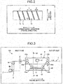
- FIG. 2 illustrates an example of the etch mask formed on the grain oriented electrical steel strip 1.
- the etch mask 1a is formed in a band shape on the surface 11 of the grain oriented electrical steel strip 1, except the linear exposed portions 1b.
- the exposed portion 1b is inclined at, for example, a predetermined inclination angle ⁇ with respect to a longitudinal direction (travel direction) of the grain oriented electrical steel strip 1.
- the width of the exposed portion 1b in the travel direction is denoted by d, and the width of the etch mask 1a in the travel direction is denoted by L.
- the etch-resist-coating apparatus 2 includes a backup roll 2a, a gravure roll 2b, and a rubber transfer roll 2c.
- the rubber transfer roll 2c is placed between the gravure roll 2b and the backup roll 2a and is in contact with both the rolls 2a and 2b.
- Recesses that match the shape of the etch mask 1a formed on the grain oriented electrical steel strip 1 are formed in the gravure roll 2b. Ink of the etch resist accumulated in the recess is transferred onto the surface 11 of the grain oriented electrical steel strip 1 via the rubber transfer roll 2c.
- the rubber transfer roll 2c sandwiches the grain oriented electrical steel strip 1 with the backup roll 2a, and coats the grain oriented electrical steel strip 1 with the ink while applying pressure to the grain oriented electrical steel strip 1.
- a resist ink having any of alkyd-based resin, epoxy-based resin, and polyethylene-based resin as a main ingredient is suitable for the ink to be used as the etch resist.
- the drying-and-baking apparatus 3 dries and bakes the etch resist ink applied to the surface 11 of the grain oriented electrical steel strip 1. Consequently, the etch mask 1a is formed on the surface 11 of the grain oriented electrical steel strip 1, with the linear exposed portions 1b being exposed from the etch mask 1a.
- the position sensor 9 and the centering apparatus 8 are placed immediately upstream of the electrolytic etching apparatus 4.
- the position sensor 9 and the centering apparatus 8 are placed on an inlet side of and in the vicinity of the electrolytic etching apparatus 4.
- the centering apparatus 8 is placed upstream of the position sensor 9 in the travel direction of the grain oriented electrical steel strip 1.
- the position sensor 9 detects the position of the grain oriented electrical steel strip 1 in the width direction.
- the position sensor 9 typically detects the positions of both end faces (edges) of the grain oriented electrical steel strip 1 in the width direction to detect the widthwise center position of the grain oriented electrical steel strip 1.
- the position in the width direction detected by the position sensor 9 is transmitted to the centering apparatus 8.
- the centering apparatus 8 centers the grain oriented electrical steel strip 1 on the basis of the detection result of the position sensor 9.
- the centering apparatus 8 typically adjusts the widthwise center position of the grain oriented electrical steel strip 1 on the basis of the position in the width direction acquired from the position sensor 9 so as to avoid a displacement from a predetermined line center.
- the centering apparatus 8 adjusts the position of the grain oriented electrical steel strip 1 in the width direction by, for example, inclining the rotation axis of an upstream roller 8b with respect to the rotation axis of a downstream roller 8a.
- the electrolytic etching apparatus 4 includes an electrolytic etching cell 41, the electrode 42, the conductor rolls 43a and 43b, backup rolls 44a and 44b, sink rolls 45a and 45b, the electrolytic bath 46, and a power supply 47.
- the electrolytic etching apparatus 4 immerses a part of the grain oriented electrical steel strip 1 in the electrolytic bath 46 by the sink rolls 45a and 45b in a state where the conductor rolls 43a and 43b are in contact with the grain oriented electrical steel strip 1 and makes the grain oriented electrical steel strip 1 face the electrode 42 between the sink rolls 45a and 45b.
- the electrolytic etching apparatus 4 passes electric current between the conductor rolls 43a and 43b and the electrode 42 and forms the linear grooves by the electrolytic etching process in the surface 11 of the grain oriented electrical steel strip 1.
- the electrolytic bath 46 is stored in the electrolytic etching cell 41.
- the electrolytic bath 46 is an electrolyte such as a NaCl solution or KCl solution.
- the electrode 42 is placed in the electrolytic bath 46.
- the conductor rolls 43a and 43b and the backup rolls 44a and 44b are placed above a liquid level of the electrolytic bath 46 in the electrolytic etching cell 41.
- the inlet-side conductor roll 43a and the inlet-side backup roll 44a are placed on an inlet side in the electrolytic etching cell 41.
- the outlet-side conductor roll 43b and the outlet-side backup roll 44b are placed on an outlet side in the electrolytic etching cell 41.
- the conductor rolls 43a and 43b are anodes that come into contact with the grain oriented electrical steel strip 1.
- the grain oriented electrical steel strip 1 is sandwiched between the inlet-side conductor roll 43a and the inlet-side backup roll 44a to maintain the state where the grain oriented electrical steel strip 1 and the inlet-side conductor roll 43a are in contact with each other. Moreover, the grain oriented electrical steel strip 1 is sandwiched between the outlet-side conductor roll 43b and the outlet-side backup roll 44b to maintain the contact state of the grain oriented electrical steel strip 1 and the outlet-side conductor roll 43b.
- the sink rolls 45a and 45b are immersed in the electrolytic bath 46 to immerse the grain oriented electrical steel strip 1 in the electrolytic bath 46.
- the inlet-side sink roll 45a is placed on the inlet side and the outlet-side sink roll 45b on the outlet side.
- the grain oriented electrical steel strip 1 is carried in the electrolytic etching cell 41 in a state of being wound around the inlet-side backup roll 44a, the inlet-side sink roll 45a, the outlet-side sink roll 45b, and the outlet backup roll 44b.
- the grain oriented electrical steel strip 1 to be carried enters the electrolytic bath 46 between the inlet-side backup roll 44a and the inlet-side sink roll 45a, passes below the sink rolls 45a and 45b, and goes out of the electrolytic bath 46 between the outlet-side sink roll 45b and the outlet-side backup roll 44b.
- the electrode 42 is a cathode paired with the conductor rolls 43a and 43b.
- the electrode 42 is connected to a cathode side of the power supply 47, and the conductor rolls 43a and 43b are connected to an anode side of the power supply 47.
- a current circuit is configured including the power supply 47, the conductor roll 43a, 43b, the grain oriented electrical steel strip 1, the electrolytic bath 46, and the electrode 42.
- the current density in the electrolytic etching process is preferably in a range of 1 to 100 [A/dm 2 ]. If the current density is too low, a sufficient etching effect cannot be obtained. Moreover, if the current density is too high, the etch mask 1a is damaged.
- the flat plate-shaped electrode 42 is placed at a position facing the surface 11 of the grain oriented electrical steel strip 1 in the electrolytic bath 46. More specifically, the electrode 42 is placed below the grain oriented electrical steel strip 1 in the electrolytic bath 46, and faces an area of the surface 11 of the grain oriented electrical steel strip 1 between the inlet-side sink roll 45a and the outlet-side sink roll 45b.
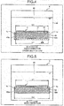
- FIG. 4 illustrates a cross section IV-IV of FIG. 3 .
- the electrode 42 is placed such that the line center agrees with the widthwise center line of the electrode 42.
- a width L1 of the grain oriented electrical steel strip 1 is equal or substantially equal to a width L2 of the electrode 42. Consequently, unnecessary electrolysis near ends 1e of the grain oriented electrical steel strip 1 in the width direction can be restrained.
- the width L2 of the electrode 42 is preferably the width L1 of the grain oriented electrical steel strip 1 ⁇ 10 [mm]. In the embodiment, the width L2 of the electrode 42 is equal to the width L1 of the grain oriented electrical steel strip 1.
- a width L3 of an electrode 50 is larger by a given length than the width L1 of the grain oriented electrical steel strip 1 as in a comparative example of FIG. 5 , parts that are not targeted for electrolysis, that is, parts other than the exposed portions 1b, are electroetched at the ends 1e of the grain oriented electrical steel strip 1 in the width direction. Moreover, ends of the exposed portion 1b in the width direction are excessively electroetched compared with its center. In contrast, in the electrolytic etching apparatus 4 of the embodiment, the electrolytic etching process is restrained from being unnecessarily performed or being excessively performed at the ends 1e in the width direction since the width L2 of the electrode 42 is similar to the width L1 of the grain oriented electrical steel strip 1.
- side surfaces 42a of the electrode 42 in the width direction are covered with an insulating material 48 as illustrated in FIG. 4 .
- side surfaces 50a of the electrode 50 are in contact with the electrolytic bath 46. Accordingly, the current flows from the grain oriented electrical steel strip 1 to the side surfaces 50a of the electrode 50. Consequently, the value of the current (current density) flowing through the end 1e of the grain oriented electrical steel strip 1 in the width direction becomes larger than the value of the current (current density) flowing through the center in the width direction; accordingly, the end in the width direction is overetched.
- the insulating material 48 restricts the flow of the current from the grain oriented electrical steel strip 1 to the side surface 42a of the electrode 42. Consequently, the end 1e of the grain oriented electrical steel strip 1 in the width direction is restrained from being excessively electroetched.
- a back surface 42b of the electrode 42 is also covered with the insulating material 48. Consequently, the current is restrained from flowing from the grain oriented electrical steel strip 1 to the back surface 42b of the electrode 42.
- Table 1 illustrates test conditions and results of first to sixth examples and the comparative example.
- the grain oriented electrical steel strip 1 is a steel strip with a thickness of 0.22 [mm] containing Si: 3.0 [mass%].
- a steel strip width L1 after the final cold rolling is 1,000 [mm].
- a resist ink containing epoxy-based resin as a main ingredient was used as the etch resist.
- the drying and baking temperature are 100 [°C].
- the thickness of an etch mask is 3 [ ⁇ m].
- the electrolytic etching apparatus 4 After the etch-resist-coating apparatus 2 and the drying-and-baking apparatus 3 form the etch mask 1a on the surface 11 of the grain oriented electrical steel strip 1, the electrolytic etching apparatus 4 performs an electrolytic etching process on the grain oriented electrical steel strip 1 by direct electrification.
- the electrolytic bath 46 is a NaCl solution.
- Target values of a groove shape of the linear groove are the width: 150 [ ⁇ m], the depth: 20 [ ⁇ m], and the groove interval: 3 [mm].
- the grain oriented electrical steel strip 1 passes through the etch-resist-removing apparatus 5, the water rinse tank 6, and the rinse tank 7 to remove the etch mask 1a from the surface 11.
- the groove depth of the linear groove was measured after the etch mask 1a was removed.
- Ten points to measure the groove depth are set at regular intervals from one end to the other end along the width direction of the grain oriented electrical steel strip 1. The average and variation of the groove depths were calculated from the measurement values of the 10 points.
- the grain oriented electrical steel strip 1 from which the etch mask 1a is removed is decarburized and annealed. Final annealing is subsequently performed on the grain oriented electrical steel strip 1.
- a magnetic property (iron loss W 17/50 [W/kg]) of the grain oriented electrical steel strip 1 obtained in this manner was measured. 10 points to measure the magnetic property are set at regular intervals from one end to the other end along the width direction of the grain oriented electrical steel strip 1. The average and variation of the iron loss W 17/50 were calculated from the measurement values of the 10 points.
- centering control is performed by the centering apparatus 8.
- the examples are different in the size of the width L2 of the electrode 42 and the presence or absence of the insulating material 48 covering the side surfaces 42a of the electrode 42 in the width direction.
- the first example is as follows: centering control: done, the width L2 of the electrode 42: 1,010 [mm] (the width L1 of the grain oriented electrical steel strip 1 + 10 [mm]), and the insulating material 48: absent.
- the second example is different from the first example in that the width L2 of the electrode 42 is 1,000 [mm].
- the example 3 is different from the first example in that the width L2 of the electrode 42 is 990 [mm] (the width L1 of the grain oriented electrical steel strip 1 - 10 [mm]).
- the fourth example is different from the first example in that the insulating material 48 is present.
- the fifth example is different from the first example in the respects that the width L2 of the electrode 42 is 1,000 [mm], and the insulating material 48 is present.
- the sixth example is different from the first example in the respects that the width L2 of the electrode 42 is 990 [mm], and the insulating material 48 is present.
- the comparative example is as follows: centering control: not done, the width L2 of the electrode 42: 1,010 [mm], and the insulating material 48: absent.
- the average groove depth deviates by 0.14 [ ⁇ m] from a target value (20 [ ⁇ m]) in the comparative example.
- a deviation of the average from the target value of the groove depth is 0.04 [ ⁇ m] at the maximum.
- the distribution width of the groove depth is ⁇ 0.5 [ ⁇ m] in the comparative example while the distribution width of the groove depth is reduced to ⁇ 0.09 [ ⁇ m] at the maximum in the examples.
- the iron loss W 17/50 See the iron loss W 17/50 .
- the average is 0.752 [W/kg] in the comparative example while the averages are 0.720 to 0.731 [W/kg] in the examples, which are good.
- the variation in the iron loss W 17/50 is ⁇ 0.020 [W/kg] in the comparative example while the maximum variation is ⁇ 0.009 [W/kg] in the examples, which is less than half the variation of the comparative example.
- the fifth example is the best in the accuracy of the groove depth and the value of the iron loss W 17/50 .
- the method for continuous electrolytic etching of a grain oriented electrical steel strip of the embodiment includes the mask formation step, the centering step, and the groove formation step.
- the position sensor 9 and the centering apparatus 8 which are placed immediately upstream of the electrolytic etching apparatus 4, center the grain oriented electrical steel strip 1 to restrain the center line of the grain oriented electrical steel strip 1 from deviating in the width direction from the center line of the electrode 42. Consequently, the imbalance of the current density in the width direction of the grain oriented electrical steel strip 1 is restrained from occurring.
- the method for continuous electrolytic etching of a grain oriented electrical steel strip of the embodiment can restrain variations in the shapes of the etched grooves along the width direction of the grain oriented electrical steel strip 1.
- the method for continuous electrolytic etching of a grain oriented electrical steel strip of the embodiment can provide a uniform shape of an etched groove in the width direction of the grain oriented electrical steel strip 1. Moreover, the current that does not contribute to the electrolytic etching process and the needless current for an unnecessary electrolytic etching process can be reduced; accordingly, the electrolysis efficiency can be increased. Moreover, interference caused by the meander in the electrolytic etching apparatus 4 can be prevented. The production occasion loss and the production yield loss due to a damage to an edge of the grain oriented electrical steel strip 1 can be reduced.
- the method for continuous electrolytic etching of a grain oriented electrical steel strip of the embodiment performs the electrolytic etching process in the groove formation step, using the electrode 42 whose width L2 is within ⁇ 10 mm of the width L1 of the grain oriented electrical steel strip 1. Consequently, the current density at the end of the grain oriented electrical steel strip 1 in the width direction is restrained from being different from the current density at the center. Hence, variations in the shapes of the etched grooves along the width direction of the grain oriented electrical steel strip 1 are restrained.
- the method for continuous electrolytic etching of a grain oriented electrical steel strip of the embodiment performs the electrolytic etching process in the groove formation step, using the electrode 42 whose side surfaces 42a in the width direction are covered with the insulating material 48. Consequently, the current is restricted in flowing between the grain oriented electrical steel strip 1 and the side surface 42a of the electrode 42.
- the current density at the end of the grain oriented electrical steel strip 1 in the width direction is restrained from becoming larger than the current density at the center.
- variations in the shapes of the etched grooves along the width direction of the grain oriented electrical steel strip 1 are restrained.
- the apparatus 100 for continuous electrolytic etching of a grain oriented electrical steel strip of the embodiment includes the mask-forming apparatus (the etch-resist-coating apparatus 2 and the drying-and-baking apparatus 3), the electrolytic etching apparatus 4, the position sensor 9, and the centering apparatus 8.
- the centering apparatus 8 centers the grain oriented electrical steel strip 1 on the basis of a detection result of the position sensor 9. Accordingly, the center line of the grain oriented electrical steel strip 1 is restrained from deviating in the width direction from the center line of the electrode 42. Consequently, the imbalance of the current density in the width direction of the grain oriented electrical steel strip 1 is restrained from occurring.
- the apparatus 100 for continuous electrolytic etching of a grain oriented electrical steel strip of the embodiment can restrain variations in the shapes of the etched grooves along the width direction of the grain oriented electrical steel strip 1.
- the etch-resist-coating apparatus 2 which coats the grain oriented electrical steel strip 1 with an etch resist, is not limited to the apparatus described above.
- the etch-resist-coating apparatus 2 can suitably use any method of gravure printing without an offset roll, flat offset printing, screen printing, and the like. Gravure offset printing is suitable since, for example, continuous printing for a coil is easily performed, a stable print surface can be obtained, and control over the thickness of a resist is easy.
- the present invention can provide a method for continuous electrolytic etching of a grain oriented electrical steel strip and an apparatus for continuous electrolytic etching of a grain oriented electrical steel strip, which can restrain variations in the shapes of etched grooves along a width direction of a steel strip.
Landscapes
- Chemical & Material Sciences (AREA)
- Engineering & Computer Science (AREA)
- Organic Chemistry (AREA)
- Metallurgy (AREA)
- Materials Engineering (AREA)
- Physics & Mathematics (AREA)
- Mechanical Engineering (AREA)
- Electrochemistry (AREA)
- Chemical Kinetics & Catalysis (AREA)
- Crystallography & Structural Chemistry (AREA)
- Thermal Sciences (AREA)
- Manufacturing & Machinery (AREA)
- Electromagnetism (AREA)
- Dispersion Chemistry (AREA)
- Power Engineering (AREA)
- Electroplating Methods And Accessories (AREA)
- Manufacturing Of Steel Electrode Plates (AREA)
- ing And Chemical Polishing (AREA)
Abstract
Description
- The present invention relates to a method for continuous electrolytic etching of a grain oriented electrical steel strip and an apparatus for continuous electrolytic etching of a grain oriented electrical steel strip.
- A technology has conventionally been disclosed which improves the properties of a grain oriented electrical steel strip (hereinafter simply referred to as "steel strip" as appropriate) by printing an etch resist on a surface of the steel strip with an electrically insulating ink, and subsequently forming an etch pattern by an electrolytic etching process on the surface of the steel strip where the etch resist has been printed (refer to Patent Literature 1). An electrolytic etching process that is excellent in the stability of an etched state of a product has been requested to industrially perform such a technology for improving the properties of a steel strip using such an electrolytic etching process.
-
Patent Literature 2 proposes a method for obtaining the capability of uniform etching in a width direction of a steel strip by covering both sides of the steel strip and restraining the flow of an electrolyte in the width direction of the steel strip to obtain a uniform cross-sectional shape of a groove in the width direction. -
- Patent Literature 1: Japanese Examined Patent Application Publication No.
H8-6140 - Patent Literature 2: Japanese Patent Application Laid-open Patent Publication No.
H10-204698 - There is still room for improvement in increasing the stability of an etched state. If, for example, the width of an electrode is too large as compared to the width of a steel strip, the amount of electrolytic etching at an edge of the steel strip becomes larger than the amount of electrolytic etching at any other portions such as the center of the steel strip due to a current flowing from a portion of the electrode, the portion protruding outward of the steel strip. Accordingly, there arise problems such as the deepening of and the widening of a groove at the edge of the steel strip and the impossibility of obtaining a widthwise uniform shape of the groove.
- An object of the present invention is to provide a method for continuous electrolytic etching of a grain oriented electrical steel strip and an apparatus for continuous electrolytic etching of a grain oriented electrical steel strip, which can restrain variations in the shapes of etched grooves along a width direction of a steel strip.
- A method for continuous electrolytic etching of a grain oriented electrical steel strip according to the present invention includes a mask formation step of forming an etch mask on a surface of a grain oriented electrical steel strip cold-rolled to final thickness with a linear exposed portion exposed from the etch mask; a centering step of centering the grain oriented electrical steel strip with a position sensor and a centering apparatus, which are placed immediately upstream of an electrolytic etching apparatus; and a groove formation step of performing an electrolytic etching process in which electrolytic etching is performed in the electrolytic etching apparatus to form a linear groove on the surface of the grain oriented electrical steel strip by passing electric current between a conductor roll and an electrode placed in an electrolytic bath while the grain oriented electrical steel strip is brought into contact with the conductor roll, the grain oriented electrical steel strip is immersed in the electrolytic bath and the grain oriented electrical steel strip is facing the electrode.
- Moreover, in the above-described method for continuous electrolytic etching of a grain oriented electrical steel strip according to the present invention, the groove formation step includes performing the electrolytic etching process using the electrode whose width is within +10 mm of a steel strip width of the grain oriented electrical steel strip.
- Moreover, in the above-described method for continuous electrolytic etching of a grain oriented electrical steel strip according to the present invention, the groove formation step includes performing the electrolytic etching process using the electrode whose side surface in the width direction is covered with an insulating material.
- An apparatus for continuous electrolytic etching of a grain oriented electrical steel strip according to the present invention includes a mask-forming apparatus configured to form an etch mask on a surface of a grain oriented electrical steel strip cold-rolled to final thickness with a linear exposed portion being exposed from the etch mask; an electrolytic etching apparatus including an electrolytic bath, an electrode placed in the electrolytic bath, and a conductor roll, the electrolytic etching apparatus performing an electrolytic etching process in which electrolytic etching is performed to form a linear groove on the surface of the grain oriented electrical steel strip by passing electric current between the conductor roll and the electrode while the grain oriented electrical steel strip is brought into contact with the conductor roll, the grain oriented electrical steel strip is immersed in the electrolytic bath, and the grain oriented electrical steel strip is facing the electrode; a position sensor, placed immediately upstream of the electrolytic etching apparatus, to detect a position of the grain oriented electrical steel strip in a width direction; and a centering apparatus, placed immediately upstream of the electrolytic etching apparatus, to center the grain oriented electrical steel strip on the basis of a detection result of the position sensor.
- A method for continuous electrolytic etching of a grain oriented electrical steel strip and an apparatus for continuous electrolytic etching of a grain oriented electrical steel strip according to the present invention can suppress variations in the shapes of etched grooves in a width direction of a steel strip.
-
-
FIG. 1 is a schematic configuration diagram of an apparatus for continuous electrolytic etching of a grain oriented electrical steel strip according to an embodiment. -
FIG. 2 is a plan view illustrating an example of an etch mask. -
FIG. 3 is a diagram illustrating main parts of the apparatus for continuous electrolytic etching of a grain oriented electrical steel strip according to the embodiment. -
FIG. 4 is a cross-sectional view of an electrolytic etching apparatus according to the embodiment. -
FIG. 5 is a cross-sectional view of an electrolytic etching apparatus according to a comparative example. Description of Embodiments - A method for continuous electrolytic etching of a grain oriented electrical steel strip and an apparatus for continuous electrolytic etching of a grain oriented electrical steel strip according to an embodiment of the present invention are described in detail hereinafter with reference to the drawings. The invention is not limited by the embodiment. Moreover, components in the following embodiment include those that are easily conceivable by a person skilled in the art, or substantially the same ones.
- The embodiment is described with reference to
FIGS. 1 to 5 . The embodiment relates to a method for continuous electrolytic etching of a grain oriented electrical steel strip and an apparatus for continuous electrolytic etching of a grain oriented electrical steel strip. The method for continuous electrolytic etching of a grain oriented electrical steel strip of the embodiment forms linear grooves on a surface of a grain oriented electrical steel strip cold-rolled to final thickness by, for example, selectively forming an etch mask on the surface of the grain oriented electrical steel strip, continuously loading the grain oriented electrical steel strip into an electrolytic cell, and performing an electrolytic etching process thereon.FIG. 1 is a schematic configuration diagram of the apparatus for continuous electrolytic etching of a grain oriented electrical steel strip according to the embodiment of the present invention. - As illustrated in
FIG. 1 , anapparatus 100 for continuous electrolytic etching of a grain oriented electrical steel strip according to the embodiment (hereinafter also simply referred to as the "continuous electrolytic etching apparatus") includes an etch-resist-coating apparatus 2, a drying-and-baking apparatus 3, anelectrolytic etching apparatus 4, an etch-resist-removingapparatus 5, awater rinse tank 6, arinse tank 7, acentering apparatus 8, and aposition sensor 9. Moreover, the method for continuous electrolytic etching of the embodiment, which is implemented by the continuouselectrolytic etching apparatus 100, includes a mask formation step, a centering step, and a groove formation step. - The mask formation step is the step of forming an
etch mask 1a on asurface 11 of a grain orientedelectrical steel strip 1 cold-rolled to final thickness with linear exposedportions 1b being exposed from theetch mask 1a (refer toFIG. 2 ). The continuouselectrolytic etching apparatus 100 includes the etch-resist-coating apparatus 2 and the drying-and-baking apparatus 3 as a mask-forming apparatus. The etch-resist-coating apparatus 2 and the drying-and-baking apparatus 3 execute the mask formation step. The continuouselectrolytic etching apparatus 100 coats, with an etch resist, thesurface 11 of the grain orientedelectrical steel strip 1 cold-rolled to final thickness, dries and bakes the grain orientedelectrical steel strip 1, and selectively forms theetch mask 1a. - The centering step is the step of centering the grain oriented
electrical steel strip 1 with theposition sensor 9 and thecentering apparatus 8, which are placed immediately upstream of theelectrolytic etching apparatus 4. The centering step restrains a displacement of the grain orientedelectrical steel strip 1 from a line center. Consequently, variations in current densities in the electrolytic etching process are restrained; accordingly, linear grooves of a uniform shape are formed. - The groove formation step is the step of performing the electrolytic etching process in which electrolytic etching is performed in the
electrolytic etching apparatus 4 to form the linear grooves on thesurface 11 of the grain orientedelectrical steel strip 1 by passing electric current betweenconductor rolls electrode 42 placed in anelectrolytic bath 46 while the grain orientedelectrical steel strip 1 is brought into contact with theconductor rolls electrical steel strip 1 is immersed in theelectrolytic bath 46 and the grain orientedelectrical steel strip 1 is facing theelectrode 42. - The
etch mask 1a is removed by the etch-resist-removingapparatus 5 from thesurface 11 of the grain orientedelectrical steel strip 1 on which the linear grooves have been introduced. The grain orientedelectrical steel strip 1 is then cleaned in thewater rinse tank 6 and therinse tank 7. The method for continuous electrolytic etching of a grain oriented electrical steel strip and theapparatus 100 for continuous electrolytic etching of a grain oriented electrical steel strip of the embodiment are described in detail below. - The grain oriented
electrical steel strip 1 cold-rolled to the final thickness is carried by transport devices such as transport rolls sequentially to the etch-resist-coating apparatus 2, the drying-and-baking apparatus 3, theelectrolytic etching apparatus 4, the etch-resist-removingapparatus 5, thewater rinse tank 6, and therinse tank 7 in this order. The etch-resist-coating apparatus 2 coats thesurface 11 of the grain orientedelectrical steel strip 1 with an etch resist. The etch-resist-coating apparatus 2 of the embodiment coats thesurface 11 of the grain orientedelectrical steel strip 1, except the linear exposedportions 1b, with the etch resist by gravure offset printing. -
FIG. 2 illustrates an example of the etch mask formed on the grain orientedelectrical steel strip 1. Theetch mask 1a is formed in a band shape on thesurface 11 of the grain orientedelectrical steel strip 1, except the linear exposedportions 1b. The exposedportion 1b is inclined at, for example, a predetermined inclination angle θ with respect to a longitudinal direction (travel direction) of the grain orientedelectrical steel strip 1. The width of the exposedportion 1b in the travel direction is denoted by d, and the width of theetch mask 1a in the travel direction is denoted by L. - Returning to
FIG. 1 , the etch-resist-coating apparatus 2 includes abackup roll 2a, agravure roll 2b, and arubber transfer roll 2c. Therubber transfer roll 2c is placed between thegravure roll 2b and thebackup roll 2a and is in contact with both therolls etch mask 1a formed on the grain orientedelectrical steel strip 1 are formed in thegravure roll 2b. Ink of the etch resist accumulated in the recess is transferred onto thesurface 11 of the grain orientedelectrical steel strip 1 via therubber transfer roll 2c. Therubber transfer roll 2c sandwiches the grain orientedelectrical steel strip 1 with thebackup roll 2a, and coats the grain orientedelectrical steel strip 1 with the ink while applying pressure to the grain orientedelectrical steel strip 1. A resist ink having any of alkyd-based resin, epoxy-based resin, and polyethylene-based resin as a main ingredient is suitable for the ink to be used as the etch resist. - The drying-and-baking
apparatus 3 dries and bakes the etch resist ink applied to thesurface 11 of the grain orientedelectrical steel strip 1. Consequently, theetch mask 1a is formed on thesurface 11 of the grain orientedelectrical steel strip 1, with the linear exposedportions 1b being exposed from theetch mask 1a. - As illustrated in
FIG. 3 , theposition sensor 9 and the centeringapparatus 8 are placed immediately upstream of theelectrolytic etching apparatus 4. In other words, theposition sensor 9 and the centeringapparatus 8 are placed on an inlet side of and in the vicinity of theelectrolytic etching apparatus 4. The centeringapparatus 8 is placed upstream of theposition sensor 9 in the travel direction of the grain orientedelectrical steel strip 1. Theposition sensor 9 detects the position of the grain orientedelectrical steel strip 1 in the width direction. Theposition sensor 9 typically detects the positions of both end faces (edges) of the grain orientedelectrical steel strip 1 in the width direction to detect the widthwise center position of the grain orientedelectrical steel strip 1. The position in the width direction detected by theposition sensor 9 is transmitted to the centeringapparatus 8. The centeringapparatus 8 centers the grain orientedelectrical steel strip 1 on the basis of the detection result of theposition sensor 9. The centeringapparatus 8 typically adjusts the widthwise center position of the grain orientedelectrical steel strip 1 on the basis of the position in the width direction acquired from theposition sensor 9 so as to avoid a displacement from a predetermined line center. The centeringapparatus 8 adjusts the position of the grain orientedelectrical steel strip 1 in the width direction by, for example, inclining the rotation axis of anupstream roller 8b with respect to the rotation axis of a downstream roller 8a. - The
electrolytic etching apparatus 4 includes anelectrolytic etching cell 41, theelectrode 42, the conductor rolls 43a and 43b, backup rolls 44a and 44b, sink rolls 45a and 45b, theelectrolytic bath 46, and apower supply 47. Theelectrolytic etching apparatus 4 immerses a part of the grain orientedelectrical steel strip 1 in theelectrolytic bath 46 by the sink rolls 45a and 45b in a state where the conductor rolls 43a and 43b are in contact with the grain orientedelectrical steel strip 1 and makes the grain orientedelectrical steel strip 1 face theelectrode 42 between the sink rolls 45a and 45b. Theelectrolytic etching apparatus 4 passes electric current between the conductor rolls 43a and 43b and theelectrode 42 and forms the linear grooves by the electrolytic etching process in thesurface 11 of the grain orientedelectrical steel strip 1. - The
electrolytic bath 46 is stored in theelectrolytic etching cell 41. Theelectrolytic bath 46 is an electrolyte such as a NaCl solution or KCl solution. Theelectrode 42 is placed in theelectrolytic bath 46. The conductor rolls 43a and 43b and the backup rolls 44a and 44b are placed above a liquid level of theelectrolytic bath 46 in theelectrolytic etching cell 41. The inlet-side conductor roll 43a and the inlet-side backup roll 44a are placed on an inlet side in theelectrolytic etching cell 41. The outlet-side conductor roll 43b and the outlet-side backup roll 44b are placed on an outlet side in theelectrolytic etching cell 41. The conductor rolls 43a and 43b are anodes that come into contact with the grain orientedelectrical steel strip 1. The grain orientedelectrical steel strip 1 is sandwiched between the inlet-side conductor roll 43a and the inlet-side backup roll 44a to maintain the state where the grain orientedelectrical steel strip 1 and the inlet-side conductor roll 43a are in contact with each other. Moreover, the grain orientedelectrical steel strip 1 is sandwiched between the outlet-side conductor roll 43b and the outlet-side backup roll 44b to maintain the contact state of the grain orientedelectrical steel strip 1 and the outlet-side conductor roll 43b. - The sink rolls 45a and 45b are immersed in the
electrolytic bath 46 to immerse the grain orientedelectrical steel strip 1 in theelectrolytic bath 46. In theelectrolytic etching cell 41, the inlet-side sink roll 45a is placed on the inlet side and the outlet-side sink roll 45b on the outlet side. The grain orientedelectrical steel strip 1 is carried in theelectrolytic etching cell 41 in a state of being wound around the inlet-side backup roll 44a, the inlet-side sink roll 45a, the outlet-side sink roll 45b, and theoutlet backup roll 44b. The grain orientedelectrical steel strip 1 to be carried enters theelectrolytic bath 46 between the inlet-side backup roll 44a and the inlet-side sink roll 45a, passes below the sink rolls 45a and 45b, and goes out of theelectrolytic bath 46 between the outlet-side sink roll 45b and the outlet-side backup roll 44b. - The
electrode 42 is a cathode paired with the conductor rolls 43a and 43b. Theelectrode 42 is connected to a cathode side of thepower supply 47, and the conductor rolls 43a and 43b are connected to an anode side of thepower supply 47. In theelectrolytic etching apparatus 4, a current circuit is configured including thepower supply 47, theconductor roll electrical steel strip 1, theelectrolytic bath 46, and theelectrode 42. The current density in the electrolytic etching process is preferably in a range of 1 to 100 [A/dm2]. If the current density is too low, a sufficient etching effect cannot be obtained. Moreover, if the current density is too high, theetch mask 1a is damaged. - As illustrated in
FIG. 3 , the flat plate-shapedelectrode 42 is placed at a position facing thesurface 11 of the grain orientedelectrical steel strip 1 in theelectrolytic bath 46. More specifically, theelectrode 42 is placed below the grain orientedelectrical steel strip 1 in theelectrolytic bath 46, and faces an area of thesurface 11 of the grain orientedelectrical steel strip 1 between the inlet-side sink roll 45a and the outlet-side sink roll 45b. -
FIG. 4 illustrates a cross section IV-IV ofFIG. 3 . Theelectrode 42 is placed such that the line center agrees with the widthwise center line of theelectrode 42. As illustrated inFIG. 4 , a width L1 of the grain orientedelectrical steel strip 1 is equal or substantially equal to a width L2 of theelectrode 42. Consequently, unnecessary electrolysis near ends 1e of the grain orientedelectrical steel strip 1 in the width direction can be restrained. The width L2 of theelectrode 42 is preferably the width L1 of the grain orientedelectrical steel strip 1 ± 10 [mm]. In the embodiment, the width L2 of theelectrode 42 is equal to the width L1 of the grain orientedelectrical steel strip 1. If a width L3 of anelectrode 50 is larger by a given length than the width L1 of the grain orientedelectrical steel strip 1 as in a comparative example ofFIG. 5 , parts that are not targeted for electrolysis, that is, parts other than the exposedportions 1b, are electroetched at theends 1e of the grain orientedelectrical steel strip 1 in the width direction. Moreover, ends of the exposedportion 1b in the width direction are excessively electroetched compared with its center. In contrast, in theelectrolytic etching apparatus 4 of the embodiment, the electrolytic etching process is restrained from being unnecessarily performed or being excessively performed at theends 1e in the width direction since the width L2 of theelectrode 42 is similar to the width L1 of the grain orientedelectrical steel strip 1. - Moreover, in the
electrolytic etching apparatus 4 of the embodiment, side surfaces 42a of theelectrode 42 in the width direction are covered with an insulatingmaterial 48 as illustrated inFIG. 4 . In the comparative example illustrated inFIG. 5 , side surfaces 50a of theelectrode 50 are in contact with theelectrolytic bath 46. Accordingly, the current flows from the grain orientedelectrical steel strip 1 to the side surfaces 50a of theelectrode 50. Consequently, the value of the current (current density) flowing through theend 1e of the grain orientedelectrical steel strip 1 in the width direction becomes larger than the value of the current (current density) flowing through the center in the width direction; accordingly, the end in the width direction is overetched. On the other hand, in theelectrolytic etching apparatus 4 of the embodiment, the insulatingmaterial 48 restricts the flow of the current from the grain orientedelectrical steel strip 1 to theside surface 42a of theelectrode 42. Consequently, theend 1e of the grain orientedelectrical steel strip 1 in the width direction is restrained from being excessively electroetched. In the embodiment, aback surface 42b of theelectrode 42 is also covered with the insulatingmaterial 48. Consequently, the current is restrained from flowing from the grain orientedelectrical steel strip 1 to theback surface 42b of theelectrode 42. - Examples are described. Table 1 illustrates test conditions and results of first to sixth examples and the comparative example. In the examples and the comparative example, the grain oriented
electrical steel strip 1 is a steel strip with a thickness of 0.22 [mm] containing Si: 3.0 [mass%]. A steel strip width L1 after the final cold rolling is 1,000 [mm]. A resist ink containing epoxy-based resin as a main ingredient was used as the etch resist.
The drying and baking temperature are 100 [°C]. The thickness of an etch mask is 3 [µm]. - After the etch-resist-
coating apparatus 2 and the drying-and-bakingapparatus 3 form theetch mask 1a on thesurface 11 of the grain orientedelectrical steel strip 1, theelectrolytic etching apparatus 4 performs an electrolytic etching process on the grain orientedelectrical steel strip 1 by direct electrification. Theelectrolytic bath 46 is a NaCl solution. Target values of a groove shape of the linear groove are the width: 150 [µm], the depth: 20 [µm], and the groove interval: 3 [mm]. - After the electrolytic etching process is performed, the grain oriented
electrical steel strip 1 passes through the etch-resist-removingapparatus 5, the water rinsetank 6, and the rinsetank 7 to remove theetch mask 1a from thesurface 11. The groove depth of the linear groove was measured after theetch mask 1a was removed. Ten points to measure the groove depth are set at regular intervals from one end to the other end along the width direction of the grain orientedelectrical steel strip 1. The average and variation of the groove depths were calculated from the measurement values of the 10 points. - The grain oriented
electrical steel strip 1 from which theetch mask 1a is removed is decarburized and annealed. Final annealing is subsequently performed on the grain orientedelectrical steel strip 1. A magnetic property (iron loss W17/50 [W/kg]) of the grain orientedelectrical steel strip 1 obtained in this manner was measured. 10 points to measure the magnetic property are set at regular intervals from one end to the other end along the width direction of the grain orientedelectrical steel strip 1. The average and variation of the iron loss W17/50 were calculated from the measurement values of the 10 points. - In all the first to sixth examples, centering control is performed by the centering
apparatus 8. The examples are different in the size of the width L2 of theelectrode 42 and the presence or absence of the insulatingmaterial 48 covering the side surfaces 42a of theelectrode 42 in the width direction. As illustrated in table 1, the first example is as follows: centering control: done, the width L2 of the electrode 42: 1,010 [mm] (the width L1 of the grain orientedelectrical steel strip 1 + 10 [mm]), and the insulating material 48: absent. The second example is different from the first example in that the width L2 of theelectrode 42 is 1,000 [mm]. The example 3 is different from the first example in that the width L2 of theelectrode 42 is 990 [mm] (the width L1 of the grain oriented electrical steel strip 1 - 10 [mm]). The fourth example is different from the first example in that the insulatingmaterial 48 is present. The fifth example is different from the first example in the respects that the width L2 of theelectrode 42 is 1,000 [mm], and the insulatingmaterial 48 is present. The sixth example is different from the first example in the respects that the width L2 of theelectrode 42 is 990 [mm], and the insulatingmaterial 48 is present. The comparative example is as follows: centering control: not done, the width L2 of the electrode 42: 1,010 [mm], and the insulating material 48: absent. - As illustrated in table 1, the average groove depth deviates by 0.14 [µm] from a target value (20 [µm]) in the comparative example. In contrast, in the first to sixth examples, a deviation of the average from the target value of the groove depth is 0.04 [µm] at the maximum. Moreover, the distribution width of the groove depth is ±0.5 [µm] in the comparative example while the distribution width of the groove depth is reduced to ±0.09 [µm] at the maximum in the examples.
- See the iron loss W17/50. The average is 0.752 [W/kg] in the comparative example while the averages are 0.720 to 0.731 [W/kg] in the examples, which are good. Moreover, the variation in the iron loss W17/50 is ±0.020 [W/kg] in the comparative example while the maximum variation is ±0.009 [W/kg] in the examples, which is less than half the variation of the comparative example. Among the examples, the fifth example is the best in the accuracy of the groove depth and the value of the iron loss W17/50. In other words, variations in the shapes of the etched grooves along the width direction of the grain oriented
electrical steel strip 1 are effectively restrained by the multiplier effect due to the agreement of the width L2 of theelectrode 42 with the width L1 of the grain orientedelectrical steel strip 1, and the side surfaces 42a of theelectrode 42 covered with the insulatingmaterial 48 in addition to the centering control effect. Moreover, an good value of the iron loss W17/50 is obtained accordingly.Table 1 Centering control Electrode width (mm) Insulating material on side surfaces of electrode Groove depth (µm) Iron loss W17/50 (W/kg) Average Variation First example Done 1010 Absent 20.04±0.08 0.730 ±0.008 Second example Done 1000 Absent 20.02±0.06 0.728 ±0.006 Third Example Done 990 Absent 19.96±0.09 0.731 ±0.009 Fourth example Done 1010 Present 19.98±0.05 0.725 ±0.005 Fifth example Done 1000 Present 20.00±0.03 0.720 ±0.003 Sixth example Done 990 Present 20.01±0.04 0.724 ±0.004 Comparative example Not done 1010 Absent 19.86+0.50 0.752 ±0.020 - As described above, the method for continuous electrolytic etching of a grain oriented electrical steel strip of the embodiment includes the mask formation step, the centering step, and the groove formation step. In the centering step, the
position sensor 9 and the centeringapparatus 8, which are placed immediately upstream of theelectrolytic etching apparatus 4, center the grain orientedelectrical steel strip 1 to restrain the center line of the grain orientedelectrical steel strip 1 from deviating in the width direction from the center line of theelectrode 42. Consequently, the imbalance of the current density in the width direction of the grain orientedelectrical steel strip 1 is restrained from occurring. Hence, the method for continuous electrolytic etching of a grain oriented electrical steel strip of the embodiment can restrain variations in the shapes of the etched grooves along the width direction of the grain orientedelectrical steel strip 1. - The method for continuous electrolytic etching of a grain oriented electrical steel strip of the embodiment can provide a uniform shape of an etched groove in the width direction of the grain oriented
electrical steel strip 1. Moreover, the current that does not contribute to the electrolytic etching process and the needless current for an unnecessary electrolytic etching process can be reduced; accordingly, the electrolysis efficiency can be increased. Moreover, interference caused by the meander in theelectrolytic etching apparatus 4 can be prevented. The production occasion loss and the production yield loss due to a damage to an edge of the grain orientedelectrical steel strip 1 can be reduced. - Moreover, the method for continuous electrolytic etching of a grain oriented electrical steel strip of the embodiment performs the electrolytic etching process in the groove formation step, using the
electrode 42 whose width L2 is within ±10 mm of the width L1 of the grain orientedelectrical steel strip 1. Consequently, the current density at the end of the grain orientedelectrical steel strip 1 in the width direction is restrained from being different from the current density at the center. Hence, variations in the shapes of the etched grooves along the width direction of the grain orientedelectrical steel strip 1 are restrained. - Moreover, the method for continuous electrolytic etching of a grain oriented electrical steel strip of the embodiment performs the electrolytic etching process in the groove formation step, using the
electrode 42 whose side surfaces 42a in the width direction are covered with the insulatingmaterial 48. Consequently, the current is restricted in flowing between the grain orientedelectrical steel strip 1 and theside surface 42a of theelectrode 42. The current density at the end of the grain orientedelectrical steel strip 1 in the width direction is restrained from becoming larger than the current density at the center. Hence, variations in the shapes of the etched grooves along the width direction of the grain orientedelectrical steel strip 1 are restrained. - The
apparatus 100 for continuous electrolytic etching of a grain oriented electrical steel strip of the embodiment includes the mask-forming apparatus (the etch-resist-coating apparatus 2 and the drying-and-baking apparatus 3), theelectrolytic etching apparatus 4, theposition sensor 9, and the centeringapparatus 8. The centeringapparatus 8 centers the grain orientedelectrical steel strip 1 on the basis of a detection result of theposition sensor 9. Accordingly, the center line of the grain orientedelectrical steel strip 1 is restrained from deviating in the width direction from the center line of theelectrode 42. Consequently, the imbalance of the current density in the width direction of the grain orientedelectrical steel strip 1 is restrained from occurring. Hence, theapparatus 100 for continuous electrolytic etching of a grain oriented electrical steel strip of the embodiment can restrain variations in the shapes of the etched grooves along the width direction of the grain orientedelectrical steel strip 1. - The etch-resist-
coating apparatus 2, which coats the grain orientedelectrical steel strip 1 with an etch resist, is not limited to the apparatus described above. The etch-resist-coating apparatus 2 can suitably use any method of gravure printing without an offset roll, flat offset printing, screen printing, and the like. Gravure offset printing is suitable since, for example, continuous printing for a coil is easily performed, a stable print surface can be obtained, and control over the thickness of a resist is easy. - The contents described in the above embodiments can be implemented in combination as appropriate.
- The present invention can provide a method for continuous electrolytic etching of a grain oriented electrical steel strip and an apparatus for continuous electrolytic etching of a grain oriented electrical steel strip, which can restrain variations in the shapes of etched grooves along a width direction of a steel strip. Reference Signs List
-
- 1 grain oriented electrical steel strip
- 1a etch mask
- 1b exposed portion
- 11 surface
- 2 etch-resist-coating apparatus
- 2a backup roll
- 2b gravure roll
- 2c rubber transfer roll
- 3 drying and baking apparatus
- 4 electrolytic etching apparatus
- 41 electrolytic etching cell
- 42, 50 electrode
- 43a inlet-side conductor roll
- 43b outlet-side conductor roll
- 44a inlet-side backup roll
- 44b outlet-side backup roll
- 45a inlet-side sink roll
- 45b outlet-side sink roll
- 46 electrolytic bath
- 47 power supply
- 48 insulating material
- 5 etch-resist-removing apparatus
- 6 water rinse tank
- 7 rinse tank
- 8 centering apparatus
- 9 position sensor
- 100 apparatus for continuous electrolytic etching of grain oriented electrical steel strip
Claims (4)
- A method for continuous electrolytic etching of a grain oriented electrical steel strip, the method comprising:a mask formation step of forming an etch mask on a surface of a grain oriented electrical steel strip cold-rolled to final thickness with a linear exposed portion exposed from the etch mask;a centering step of centering the grain oriented electrical steel strip with a position sensor and a centering apparatus, which are placed immediately upstream of an electrolytic etching apparatus; anda groove formation step of performing an electrolytic etching process in which electrolytic etching is performed in the electrolytic etching apparatus to form a linear groove on the surface of the grain oriented electrical steel strip by passing electric current between a conductor roll and an electrode placed in an electrolytic bath while the grain oriented electrical steel strip is brought into contact with the conductor roll, the grain oriented electrical steel strip is immersed in the electrolytic bath and the grain oriented electrical steel strip is facing the electrode.
- The method for continuous electrolytic etching of a grain oriented electrical steel strip according to claim 1, wherein the groove formation step includes performing the electrolytic etching process using the electrode whose width is within ±10 mm of a steel strip width of the grain oriented electrical steel strip.
- The method for continuous electrolytic etching of a grain oriented electrical steel strip according to claim 1 or 2, wherein the groove formation step includes performing the electrolytic etching process using the electrode whose side surface in the width direction is covered with an insulating material.
- An apparatus for continuous electrolytic etching of a grain oriented electrical steel strip, the apparatus comprising:a mask-forming apparatus configured to form an etch mask on a surface of a grain oriented electrical steel strip cold-rolled to final thickness with a linear exposed portion being exposed from the etch mask;an electrolytic etching apparatus including an electrolytic bath, an electrode placed in the electrolytic bath, and a conductor roll, the electrolytic etching apparatus performing an electrolytic etching process in which electrolytic etching is performed to form a linear groove on the surface of the grain oriented electrical steel strip by passing electric current between the conductor roll and the electrode while the grain oriented electrical steel strip is brought into contact with the conductor roll, the grain oriented electrical steel strip is immersed in the electrolytic bath, and the grain oriented electrical steel strip is facing the electrode;a position sensor, placed immediately upstream of the electrolytic etching apparatus, to detect a position of the grain oriented electrical steel strip in a width direction; anda centering apparatus, placed immediately upstream of the electrolytic etching apparatus, to center the grain oriented electrical steel strip on the basis of a detection result of the position sensor.
Applications Claiming Priority (2)
| Application Number | Priority Date | Filing Date | Title |
|---|---|---|---|
| JP2015042745A JP6233334B2 (en) | 2015-03-04 | 2015-03-04 | Continuous electrolytic etching method for directional electrical steel strip and continuous electrolytic etching apparatus for directional electrical steel strip |
| PCT/JP2016/053755 WO2016140022A1 (en) | 2015-03-04 | 2016-02-09 | Method for carrying out continuous electrolytic etching on oriented magnetic steel strip, and apparatus for carrying out continuous electrolytic etching on oriented magnetic steel strip |
Publications (3)
| Publication Number | Publication Date |
|---|---|
| EP3266906A1 true EP3266906A1 (en) | 2018-01-10 |
| EP3266906A4 EP3266906A4 (en) | 2018-10-31 |
| EP3266906B1 EP3266906B1 (en) | 2020-04-08 |
Family
ID=56844754
Family Applications (1)
| Application Number | Title | Priority Date | Filing Date |
|---|---|---|---|
| EP16758717.9A Active EP3266906B1 (en) | 2015-03-04 | 2016-02-09 | Method for carrying out continuous electrolytic etching on oriented magnetic steel strip, and apparatus for carrying out continuous electrolytic etching on oriented magnetic steel strip |
Country Status (7)
| Country | Link |
|---|---|
| US (1) | US10533263B2 (en) |
| EP (1) | EP3266906B1 (en) |
| JP (1) | JP6233334B2 (en) |
| KR (1) | KR101943399B1 (en) |
| CN (1) | CN107407002B (en) |
| RU (1) | RU2676816C1 (en) |
| WO (1) | WO2016140022A1 (en) |
Families Citing this family (2)
| Publication number | Priority date | Publication date | Assignee | Title |
|---|---|---|---|---|
| KR102181758B1 (en) * | 2018-11-30 | 2020-11-24 | 주식회사 포스코 | Apparatus for eliminating scale of stainless steal strip |
| CN110894606A (en) * | 2019-10-21 | 2020-03-20 | 长沙锂安能电子科技有限公司 | Crawler-type double-gravure synchronous etching system and etching method |
Family Cites Families (22)
| Publication number | Priority date | Publication date | Assignee | Title |
|---|---|---|---|---|
| JPS5834846U (en) * | 1981-08-28 | 1983-03-07 | 住友金属工業株式会社 | centering roll |
| JPS58184370U (en) * | 1982-06-03 | 1983-12-08 | トヨタ自動車株式会社 | Hanger on overhead conveyor for transporting vehicle bodies |
| JPH07110975B2 (en) * | 1986-12-17 | 1995-11-29 | 新日本製鐵株式会社 | Iron loss reduction processing line for grain-oriented electrical steel |
| JPH0313599A (en) * | 1989-06-09 | 1991-01-22 | Nippon Steel Corp | Insoluble electrode for electroplating |
| JPH086140B2 (en) | 1990-08-01 | 1996-01-24 | 川崎製鉄株式会社 | Method for manufacturing low iron loss grain-oriented electrical steel sheet |
| JPH05320999A (en) * | 1992-05-27 | 1993-12-07 | Kawasaki Steel Corp | Method for manufacturing low iron loss grain-oriented electrical steel sheet |
| JP3020753B2 (en) * | 1992-09-30 | 2000-03-15 | 川崎製鉄株式会社 | Electron beam continuous irradiation equipment |
| JPH07188755A (en) * | 1993-12-28 | 1995-07-25 | Kawasaki Steel Corp | Iron loss reduction method for grain-oriented silicon steel sheet |
| JP4016431B2 (en) * | 1995-03-31 | 2007-12-05 | Jfeスチール株式会社 | Directional silicon steel strip manufacturing method and electrolytic etching apparatus |
| JP2839078B2 (en) * | 1995-06-21 | 1998-12-16 | 株式会社昭和鉛鉄 | Electrode |
| AT406385B (en) * | 1996-10-25 | 2000-04-25 | Andritz Patentverwaltung | METHOD AND DEVICE FOR ELECTROLYTICALLY STICKING METAL STRIPS |
| JP3666144B2 (en) * | 1996-10-29 | 2005-06-29 | Jfeスチール株式会社 | Electrolytic etching method for grain-oriented electrical steel sheet |
| JP3855336B2 (en) | 1997-01-22 | 2006-12-06 | Jfeスチール株式会社 | Continuous electrolytic etching equipment |
| JPH11199936A (en) | 1998-01-09 | 1999-07-27 | Kawasaki Steel Corp | Method of manufacturing low iron loss directional magnetic steel strip |
| JP4385535B2 (en) * | 2001-03-09 | 2009-12-16 | パナソニック株式会社 | Carbon electrode for etching and etching method of electrode foil for aluminum electrolytic capacitor using the same |
| EP1342818B1 (en) | 2002-03-04 | 2016-09-07 | Nippon Steel & Sumitomo Metal Corporation | Method and apparatus for indirect-electrification-type continuous electrolytic etching of metal strip |
| EP1699949B1 (en) * | 2003-12-23 | 2009-07-08 | Corus Staal BV | Improved metal strip electroplating |
| JP2010058192A (en) * | 2008-09-02 | 2010-03-18 | Toshiba Corp | Machining electrode, electrochemical machining device, method of electrochemical machining, and method of manufacturing structure |
| EP2843069B1 (en) | 2012-04-26 | 2019-06-05 | JFE Steel Corporation | Grain-oriented electrical steel sheet and method for manufacturing same |
| JP5971157B2 (en) * | 2013-03-11 | 2016-08-17 | Jfeスチール株式会社 | Coating apparatus and coating method |
| JP6230798B2 (en) * | 2013-03-11 | 2017-11-15 | Jfeスチール株式会社 | Coating method and coating apparatus |
| CN104345873A (en) * | 2013-08-06 | 2015-02-11 | 北大方正集团有限公司 | File operation method and file operation device for network video conference system |
-
2015
- 2015-03-04 JP JP2015042745A patent/JP6233334B2/en active Active
-
2016
- 2016-02-09 EP EP16758717.9A patent/EP3266906B1/en active Active
- 2016-02-09 RU RU2017134010A patent/RU2676816C1/en active
- 2016-02-09 WO PCT/JP2016/053755 patent/WO2016140022A1/en not_active Ceased
- 2016-02-09 US US15/550,266 patent/US10533263B2/en active Active
- 2016-02-09 CN CN201680011249.XA patent/CN107407002B/en active Active
- 2016-02-09 KR KR1020177027732A patent/KR101943399B1/en active Active
Also Published As
| Publication number | Publication date |
|---|---|
| CN107407002A (en) | 2017-11-28 |
| JP6233334B2 (en) | 2017-11-22 |
| JP2016160519A (en) | 2016-09-05 |
| RU2676816C1 (en) | 2019-01-11 |
| WO2016140022A1 (en) | 2016-09-09 |
| CN107407002B (en) | 2019-01-22 |
| EP3266906B1 (en) | 2020-04-08 |
| KR20170123330A (en) | 2017-11-07 |
| US10533263B2 (en) | 2020-01-14 |
| US20180030612A1 (en) | 2018-02-01 |
| KR101943399B1 (en) | 2019-01-29 |
| EP3266906A4 (en) | 2018-10-31 |
Similar Documents
| Publication | Publication Date | Title |
|---|---|---|
| TWI639720B (en) | Substrate for vapor deposition mask, method for producing substrate for vapor deposition mask, and method for producing vapor deposition mask | |
| EP2641999A1 (en) | Electrolytic copper foil | |
| JP6015919B2 (en) | Method for producing grain-oriented electrical steel sheet | |
| EP3266906B1 (en) | Method for carrying out continuous electrolytic etching on oriented magnetic steel strip, and apparatus for carrying out continuous electrolytic etching on oriented magnetic steel strip | |
| US11414776B2 (en) | Electrochemical processing device and method for operating electrochemical processing device | |
| KR20190041982A (en) | Vapor deposition mask substrate, vapor deposition mask substrate manufacturing method, vapor deposition mask manufacturing method, and display device manufacturing method | |
| CN108396347B (en) | Electroplating barrier, manufacturing method thereof and pattern electroplating method | |
| CN103930599A (en) | High speed horizontal electroforming apparatus for manufacturing metal foil and method for manufacturing metal foil | |
| US6726825B2 (en) | Method and apparatus for manufacturing positive electrode foil of aluminum electrolytic capacitor | |
| KR101993769B1 (en) | Apparatus for Preventing Reverse Plating of Cathode Roller In Horizontal Coating Line Printed Circuit Board of Roll to Roll Processing | |
| JP6367664B2 (en) | Partial plating method and apparatus | |
| JP6485422B2 (en) | Manufacturing method and manufacturing apparatus for grain-oriented electrical steel sheet | |
| JP2011246790A (en) | Continuous electrolytic etching method and continuous electrolytic etching device for metallic strip | |
| CN102439202A (en) | Method and device for controlling electrochemical surface processes | |
| JPH08269563A (en) | Method for producing grain-oriented silicon steel strip and electrolytic etching apparatus | |
| JPH05320999A (en) | Method for manufacturing low iron loss grain-oriented electrical steel sheet | |
| JP4157441B2 (en) | Indirect energization type continuous electrolytic etching method and indirect energization type continuous electrolytic etching apparatus for low iron loss unidirectional silicon steel sheet | |
| ES2252661T3 (en) | ELECTRODEPOSITION CHAIN WITH MECHANICAL CONVEYORS AND METHOD OF ELECTROLYTIC METALLIC COATING OF A PART TO BE HANDLED. | |
| JP3288272B2 (en) | Electroplating equipment | |
| JP4890387B2 (en) | Manufacturing method and manufacturing apparatus for grain-oriented silicon steel sheet | |
| JP6984529B2 (en) | A base material for a vapor deposition mask, a method for manufacturing a base material for a vapor deposition mask, a method for manufacturing a vapor deposition mask, and a method for manufacturing a display device. | |
| JPS5835658Y2 (en) | variable width electrode | |
| JP3258572B2 (en) | Electroplating equipment | |
| JP2004226198A (en) | Method and apparatus for measuring surface area, and plating method | |
| JPS60230999A (en) | Electrolytic treatment of steel strip |
Legal Events
| Date | Code | Title | Description |
|---|---|---|---|
| STAA | Information on the status of an ep patent application or granted ep patent |
Free format text: STATUS: THE INTERNATIONAL PUBLICATION HAS BEEN MADE |
|
| PUAI | Public reference made under article 153(3) epc to a published international application that has entered the european phase |
Free format text: ORIGINAL CODE: 0009012 |
|
| STAA | Information on the status of an ep patent application or granted ep patent |
Free format text: STATUS: REQUEST FOR EXAMINATION WAS MADE |
|
| 17P | Request for examination filed |
Effective date: 20170929 |
|
| AK | Designated contracting states |
Kind code of ref document: A1 Designated state(s): AL AT BE BG CH CY CZ DE DK EE ES FI FR GB GR HR HU IE IS IT LI LT LU LV MC MK MT NL NO PL PT RO RS SE SI SK SM TR |
|
| AX | Request for extension of the european patent |
Extension state: BA ME |
|
| DAV | Request for validation of the european patent (deleted) | ||
| DAX | Request for extension of the european patent (deleted) | ||
| A4 | Supplementary search report drawn up and despatched |
Effective date: 20180928 |
|
| RIC1 | Information provided on ipc code assigned before grant |
Ipc: C22C 38/00 20060101ALI20180924BHEP Ipc: C21D 8/12 20060101ALI20180924BHEP Ipc: C25F 3/14 20060101AFI20180924BHEP Ipc: H01F 1/16 20060101ALI20180924BHEP |
|
| GRAP | Despatch of communication of intention to grant a patent |
Free format text: ORIGINAL CODE: EPIDOSNIGR1 |
|
| STAA | Information on the status of an ep patent application or granted ep patent |
Free format text: STATUS: GRANT OF PATENT IS INTENDED |
|
| RIC1 | Information provided on ipc code assigned before grant |
Ipc: H01F 1/16 20060101ALI20191009BHEP Ipc: C25F 3/06 20060101ALI20191009BHEP Ipc: C22C 38/02 20060101ALI20191009BHEP Ipc: C21D 8/12 20060101ALI20191009BHEP Ipc: C25F 3/14 20060101AFI20191009BHEP |
|
| INTG | Intention to grant announced |
Effective date: 20191030 |
|
| GRAS | Grant fee paid |
Free format text: ORIGINAL CODE: EPIDOSNIGR3 |
|
| GRAA | (expected) grant |
Free format text: ORIGINAL CODE: 0009210 |
|
| STAA | Information on the status of an ep patent application or granted ep patent |
Free format text: STATUS: THE PATENT HAS BEEN GRANTED |
|
| AK | Designated contracting states |
Kind code of ref document: B1 Designated state(s): AL AT BE BG CH CY CZ DE DK EE ES FI FR GB GR HR HU IE IS IT LI LT LU LV MC MK MT NL NO PL PT RO RS SE SI SK SM TR |
|
| REG | Reference to a national code |
Ref country code: AT Ref legal event code: REF Ref document number: 1254495 Country of ref document: AT Kind code of ref document: T Effective date: 20200415 Ref country code: CH Ref legal event code: EP |
|
| REG | Reference to a national code |
Ref country code: DE Ref legal event code: R096 Ref document number: 602016033642 Country of ref document: DE |
|
| REG | Reference to a national code |
Ref country code: IE Ref legal event code: FG4D |
|
| REG | Reference to a national code |
Ref country code: NL Ref legal event code: MP Effective date: 20200408 |
|
| REG | Reference to a national code |
Ref country code: LT Ref legal event code: MG4D |
|
| PG25 | Lapsed in a contracting state [announced via postgrant information from national office to epo] |
Ref country code: NL Free format text: LAPSE BECAUSE OF FAILURE TO SUBMIT A TRANSLATION OF THE DESCRIPTION OR TO PAY THE FEE WITHIN THE PRESCRIBED TIME-LIMIT Effective date: 20200408 Ref country code: LT Free format text: LAPSE BECAUSE OF FAILURE TO SUBMIT A TRANSLATION OF THE DESCRIPTION OR TO PAY THE FEE WITHIN THE PRESCRIBED TIME-LIMIT Effective date: 20200408 Ref country code: IS Free format text: LAPSE BECAUSE OF FAILURE TO SUBMIT A TRANSLATION OF THE DESCRIPTION OR TO PAY THE FEE WITHIN THE PRESCRIBED TIME-LIMIT Effective date: 20200808 Ref country code: NO Free format text: LAPSE BECAUSE OF FAILURE TO SUBMIT A TRANSLATION OF THE DESCRIPTION OR TO PAY THE FEE WITHIN THE PRESCRIBED TIME-LIMIT Effective date: 20200708 Ref country code: SE Free format text: LAPSE BECAUSE OF FAILURE TO SUBMIT A TRANSLATION OF THE DESCRIPTION OR TO PAY THE FEE WITHIN THE PRESCRIBED TIME-LIMIT Effective date: 20200408 Ref country code: GR Free format text: LAPSE BECAUSE OF FAILURE TO SUBMIT A TRANSLATION OF THE DESCRIPTION OR TO PAY THE FEE WITHIN THE PRESCRIBED TIME-LIMIT Effective date: 20200709 Ref country code: FI Free format text: LAPSE BECAUSE OF FAILURE TO SUBMIT A TRANSLATION OF THE DESCRIPTION OR TO PAY THE FEE WITHIN THE PRESCRIBED TIME-LIMIT Effective date: 20200408 Ref country code: PT Free format text: LAPSE BECAUSE OF FAILURE TO SUBMIT A TRANSLATION OF THE DESCRIPTION OR TO PAY THE FEE WITHIN THE PRESCRIBED TIME-LIMIT Effective date: 20200817 |
|
| REG | Reference to a national code |
Ref country code: AT Ref legal event code: MK05 Ref document number: 1254495 Country of ref document: AT Kind code of ref document: T Effective date: 20200408 |
|
| PG25 | Lapsed in a contracting state [announced via postgrant information from national office to epo] |
Ref country code: LV Free format text: LAPSE BECAUSE OF FAILURE TO SUBMIT A TRANSLATION OF THE DESCRIPTION OR TO PAY THE FEE WITHIN THE PRESCRIBED TIME-LIMIT Effective date: 20200408 Ref country code: HR Free format text: LAPSE BECAUSE OF FAILURE TO SUBMIT A TRANSLATION OF THE DESCRIPTION OR TO PAY THE FEE WITHIN THE PRESCRIBED TIME-LIMIT Effective date: 20200408 Ref country code: RS Free format text: LAPSE BECAUSE OF FAILURE TO SUBMIT A TRANSLATION OF THE DESCRIPTION OR TO PAY THE FEE WITHIN THE PRESCRIBED TIME-LIMIT Effective date: 20200408 Ref country code: BG Free format text: LAPSE BECAUSE OF FAILURE TO SUBMIT A TRANSLATION OF THE DESCRIPTION OR TO PAY THE FEE WITHIN THE PRESCRIBED TIME-LIMIT Effective date: 20200708 |
|
| PG25 | Lapsed in a contracting state [announced via postgrant information from national office to epo] |
Ref country code: AL Free format text: LAPSE BECAUSE OF FAILURE TO SUBMIT A TRANSLATION OF THE DESCRIPTION OR TO PAY THE FEE WITHIN THE PRESCRIBED TIME-LIMIT Effective date: 20200408 |
|
| REG | Reference to a national code |
Ref country code: DE Ref legal event code: R097 Ref document number: 602016033642 Country of ref document: DE |
|
| PG25 | Lapsed in a contracting state [announced via postgrant information from national office to epo] |
Ref country code: RO Free format text: LAPSE BECAUSE OF FAILURE TO SUBMIT A TRANSLATION OF THE DESCRIPTION OR TO PAY THE FEE WITHIN THE PRESCRIBED TIME-LIMIT Effective date: 20200408 Ref country code: CZ Free format text: LAPSE BECAUSE OF FAILURE TO SUBMIT A TRANSLATION OF THE DESCRIPTION OR TO PAY THE FEE WITHIN THE PRESCRIBED TIME-LIMIT Effective date: 20200408 Ref country code: EE Free format text: LAPSE BECAUSE OF FAILURE TO SUBMIT A TRANSLATION OF THE DESCRIPTION OR TO PAY THE FEE WITHIN THE PRESCRIBED TIME-LIMIT Effective date: 20200408 Ref country code: IT Free format text: LAPSE BECAUSE OF FAILURE TO SUBMIT A TRANSLATION OF THE DESCRIPTION OR TO PAY THE FEE WITHIN THE PRESCRIBED TIME-LIMIT Effective date: 20200408 Ref country code: SM Free format text: LAPSE BECAUSE OF FAILURE TO SUBMIT A TRANSLATION OF THE DESCRIPTION OR TO PAY THE FEE WITHIN THE PRESCRIBED TIME-LIMIT Effective date: 20200408 Ref country code: AT Free format text: LAPSE BECAUSE OF FAILURE TO SUBMIT A TRANSLATION OF THE DESCRIPTION OR TO PAY THE FEE WITHIN THE PRESCRIBED TIME-LIMIT Effective date: 20200408 Ref country code: DK Free format text: LAPSE BECAUSE OF FAILURE TO SUBMIT A TRANSLATION OF THE DESCRIPTION OR TO PAY THE FEE WITHIN THE PRESCRIBED TIME-LIMIT Effective date: 20200408 Ref country code: ES Free format text: LAPSE BECAUSE OF FAILURE TO SUBMIT A TRANSLATION OF THE DESCRIPTION OR TO PAY THE FEE WITHIN THE PRESCRIBED TIME-LIMIT Effective date: 20200408 |
|
| PLBE | No opposition filed within time limit |
Free format text: ORIGINAL CODE: 0009261 |
|
| STAA | Information on the status of an ep patent application or granted ep patent |
Free format text: STATUS: NO OPPOSITION FILED WITHIN TIME LIMIT |
|
| PG25 | Lapsed in a contracting state [announced via postgrant information from national office to epo] |
Ref country code: SK Free format text: LAPSE BECAUSE OF FAILURE TO SUBMIT A TRANSLATION OF THE DESCRIPTION OR TO PAY THE FEE WITHIN THE PRESCRIBED TIME-LIMIT Effective date: 20200408 Ref country code: PL Free format text: LAPSE BECAUSE OF FAILURE TO SUBMIT A TRANSLATION OF THE DESCRIPTION OR TO PAY THE FEE WITHIN THE PRESCRIBED TIME-LIMIT Effective date: 20200408 |
|
| 26N | No opposition filed |
Effective date: 20210112 |
|
| PG25 | Lapsed in a contracting state [announced via postgrant information from national office to epo] |
Ref country code: SI Free format text: LAPSE BECAUSE OF FAILURE TO SUBMIT A TRANSLATION OF THE DESCRIPTION OR TO PAY THE FEE WITHIN THE PRESCRIBED TIME-LIMIT Effective date: 20200408 |
|
| PG25 | Lapsed in a contracting state [announced via postgrant information from national office to epo] |
Ref country code: MC Free format text: LAPSE BECAUSE OF FAILURE TO SUBMIT A TRANSLATION OF THE DESCRIPTION OR TO PAY THE FEE WITHIN THE PRESCRIBED TIME-LIMIT Effective date: 20200408 |
|
| GBPC | Gb: european patent ceased through non-payment of renewal fee |
Effective date: 20210209 |
|
| REG | Reference to a national code |
Ref country code: BE Ref legal event code: MM Effective date: 20210228 |
|
| PG25 | Lapsed in a contracting state [announced via postgrant information from national office to epo] |
Ref country code: CH Free format text: LAPSE BECAUSE OF NON-PAYMENT OF DUE FEES Effective date: 20210228 Ref country code: LU Free format text: LAPSE BECAUSE OF NON-PAYMENT OF DUE FEES Effective date: 20210209 Ref country code: LI Free format text: LAPSE BECAUSE OF NON-PAYMENT OF DUE FEES Effective date: 20210228 |
|
| PG25 | Lapsed in a contracting state [announced via postgrant information from national office to epo] |
Ref country code: GB Free format text: LAPSE BECAUSE OF NON-PAYMENT OF DUE FEES Effective date: 20210209 Ref country code: IE Free format text: LAPSE BECAUSE OF NON-PAYMENT OF DUE FEES Effective date: 20210209 |
|
| PG25 | Lapsed in a contracting state [announced via postgrant information from national office to epo] |
Ref country code: BE Free format text: LAPSE BECAUSE OF NON-PAYMENT OF DUE FEES Effective date: 20210228 |
|
| PG25 | Lapsed in a contracting state [announced via postgrant information from national office to epo] |
Ref country code: CY Free format text: LAPSE BECAUSE OF FAILURE TO SUBMIT A TRANSLATION OF THE DESCRIPTION OR TO PAY THE FEE WITHIN THE PRESCRIBED TIME-LIMIT Effective date: 20200408 |
|
| PG25 | Lapsed in a contracting state [announced via postgrant information from national office to epo] |
Ref country code: HU Free format text: LAPSE BECAUSE OF FAILURE TO SUBMIT A TRANSLATION OF THE DESCRIPTION OR TO PAY THE FEE WITHIN THE PRESCRIBED TIME-LIMIT; INVALID AB INITIO Effective date: 20160209 |
|
| PG25 | Lapsed in a contracting state [announced via postgrant information from national office to epo] |
Ref country code: MK Free format text: LAPSE BECAUSE OF FAILURE TO SUBMIT A TRANSLATION OF THE DESCRIPTION OR TO PAY THE FEE WITHIN THE PRESCRIBED TIME-LIMIT Effective date: 20200408 |
|
| PG25 | Lapsed in a contracting state [announced via postgrant information from national office to epo] |
Ref country code: TR Free format text: LAPSE BECAUSE OF FAILURE TO SUBMIT A TRANSLATION OF THE DESCRIPTION OR TO PAY THE FEE WITHIN THE PRESCRIBED TIME-LIMIT Effective date: 20200408 |
|
| PG25 | Lapsed in a contracting state [announced via postgrant information from national office to epo] |
Ref country code: MT Free format text: LAPSE BECAUSE OF FAILURE TO SUBMIT A TRANSLATION OF THE DESCRIPTION OR TO PAY THE FEE WITHIN THE PRESCRIBED TIME-LIMIT Effective date: 20200408 |
|
| PGFP | Annual fee paid to national office [announced via postgrant information from national office to epo] |
Ref country code: FR Payment date: 20251231 Year of fee payment: 11 |
|
| PGFP | Annual fee paid to national office [announced via postgrant information from national office to epo] |
Ref country code: DE Payment date: 20251230 Year of fee payment: 11 |