EP3266554A1 - Widerstandspunktschweissvorrichtung - Google Patents
Widerstandspunktschweissvorrichtung Download PDFInfo
- Publication number
- EP3266554A1 EP3266554A1 EP16758648.6A EP16758648A EP3266554A1 EP 3266554 A1 EP3266554 A1 EP 3266554A1 EP 16758648 A EP16758648 A EP 16758648A EP 3266554 A1 EP3266554 A1 EP 3266554A1
- Authority
- EP
- European Patent Office
- Prior art keywords
- electric current
- electrode force
- current supply
- resistance spot
- spot welding
- Prior art date
- Legal status (The legal status is an assumption and is not a legal conclusion. Google has not performed a legal analysis and makes no representation as to the accuracy of the status listed.)
- Granted
Links
Images


Classifications
-
- B—PERFORMING OPERATIONS; TRANSPORTING
- B23—MACHINE TOOLS; METAL-WORKING NOT OTHERWISE PROVIDED FOR
- B23K—SOLDERING OR UNSOLDERING; WELDING; CLADDING OR PLATING BY SOLDERING OR WELDING; CUTTING BY APPLYING HEAT LOCALLY, e.g. FLAME CUTTING; WORKING BY LASER BEAM
- B23K11/00—Resistance welding; Severing by resistance heating
- B23K11/10—Spot welding; Stitch welding
- B23K11/11—Spot welding
-
- B—PERFORMING OPERATIONS; TRANSPORTING
- B23—MACHINE TOOLS; METAL-WORKING NOT OTHERWISE PROVIDED FOR
- B23K—SOLDERING OR UNSOLDERING; WELDING; CLADDING OR PLATING BY SOLDERING OR WELDING; CUTTING BY APPLYING HEAT LOCALLY, e.g. FLAME CUTTING; WORKING BY LASER BEAM
- B23K11/00—Resistance welding; Severing by resistance heating
- B23K11/24—Electric supply or control circuits therefor
- B23K11/241—Electric supplies
-
- B—PERFORMING OPERATIONS; TRANSPORTING
- B23—MACHINE TOOLS; METAL-WORKING NOT OTHERWISE PROVIDED FOR
- B23K—SOLDERING OR UNSOLDERING; WELDING; CLADDING OR PLATING BY SOLDERING OR WELDING; CUTTING BY APPLYING HEAT LOCALLY, e.g. FLAME CUTTING; WORKING BY LASER BEAM
- B23K11/00—Resistance welding; Severing by resistance heating
- B23K11/10—Spot welding; Stitch welding
- B23K11/11—Spot welding
- B23K11/115—Spot welding by means of two electrodes placed opposite one another on both sides of the welded parts
-
- B—PERFORMING OPERATIONS; TRANSPORTING
- B23—MACHINE TOOLS; METAL-WORKING NOT OTHERWISE PROVIDED FOR
- B23K—SOLDERING OR UNSOLDERING; WELDING; CLADDING OR PLATING BY SOLDERING OR WELDING; CUTTING BY APPLYING HEAT LOCALLY, e.g. FLAME CUTTING; WORKING BY LASER BEAM
- B23K11/00—Resistance welding; Severing by resistance heating
- B23K11/16—Resistance welding; Severing by resistance heating taking account of the properties of the material to be welded
-
- B—PERFORMING OPERATIONS; TRANSPORTING
- B23—MACHINE TOOLS; METAL-WORKING NOT OTHERWISE PROVIDED FOR
- B23K—SOLDERING OR UNSOLDERING; WELDING; CLADDING OR PLATING BY SOLDERING OR WELDING; CUTTING BY APPLYING HEAT LOCALLY, e.g. FLAME CUTTING; WORKING BY LASER BEAM
- B23K11/00—Resistance welding; Severing by resistance heating
- B23K11/24—Electric supply or control circuits therefor
- B23K11/25—Monitoring devices
-
- B—PERFORMING OPERATIONS; TRANSPORTING
- B23—MACHINE TOOLS; METAL-WORKING NOT OTHERWISE PROVIDED FOR
- B23K—SOLDERING OR UNSOLDERING; WELDING; CLADDING OR PLATING BY SOLDERING OR WELDING; CUTTING BY APPLYING HEAT LOCALLY, e.g. FLAME CUTTING; WORKING BY LASER BEAM
- B23K11/00—Resistance welding; Severing by resistance heating
- B23K11/24—Electric supply or control circuits therefor
- B23K11/25—Monitoring devices
- B23K11/252—Monitoring devices using digital means
- B23K11/253—Monitoring devices using digital means the measured parameter being a displacement or a position
-
- B—PERFORMING OPERATIONS; TRANSPORTING
- B23—MACHINE TOOLS; METAL-WORKING NOT OTHERWISE PROVIDED FOR
- B23K—SOLDERING OR UNSOLDERING; WELDING; CLADDING OR PLATING BY SOLDERING OR WELDING; CUTTING BY APPLYING HEAT LOCALLY, e.g. FLAME CUTTING; WORKING BY LASER BEAM
- B23K11/00—Resistance welding; Severing by resistance heating
- B23K11/24—Electric supply or control circuits therefor
- B23K11/25—Monitoring devices
- B23K11/252—Monitoring devices using digital means
- B23K11/255—Monitoring devices using digital means the measured parameter being a force
-
- B—PERFORMING OPERATIONS; TRANSPORTING
- B23—MACHINE TOOLS; METAL-WORKING NOT OTHERWISE PROVIDED FOR
- B23K—SOLDERING OR UNSOLDERING; WELDING; CLADDING OR PLATING BY SOLDERING OR WELDING; CUTTING BY APPLYING HEAT LOCALLY, e.g. FLAME CUTTING; WORKING BY LASER BEAM
- B23K2101/00—Articles made by soldering, welding or cutting
- B23K2101/006—Vehicles
-
- B—PERFORMING OPERATIONS; TRANSPORTING
- B23—MACHINE TOOLS; METAL-WORKING NOT OTHERWISE PROVIDED FOR
- B23K—SOLDERING OR UNSOLDERING; WELDING; CLADDING OR PLATING BY SOLDERING OR WELDING; CUTTING BY APPLYING HEAT LOCALLY, e.g. FLAME CUTTING; WORKING BY LASER BEAM
- B23K2103/00—Materials to be soldered, welded or cut
- B23K2103/02—Iron or ferrous alloys
- B23K2103/04—Steel or steel alloys
-
- B—PERFORMING OPERATIONS; TRANSPORTING
- B23—MACHINE TOOLS; METAL-WORKING NOT OTHERWISE PROVIDED FOR
- B23K—SOLDERING OR UNSOLDERING; WELDING; CLADDING OR PLATING BY SOLDERING OR WELDING; CUTTING BY APPLYING HEAT LOCALLY, e.g. FLAME CUTTING; WORKING BY LASER BEAM
- B23K2103/00—Materials to be soldered, welded or cut
- B23K2103/02—Iron or ferrous alloys
- B23K2103/04—Steel or steel alloys
- B23K2103/05—Stainless steel
Definitions
- the present invention relates to a resistance spot welding device for resistance spot welding, which is one type of lap resistance welding.
- a sheet set 3 including at least two overlapping steel sheets (in this case, two steel sheets including a lower steel sheet 1 and an upper steel sheet 2) is held between a vertical pair of electrodes (a lower electrode 4 and an upper electrode 5), and an electric current is applied under pressure to melt a contact region between the steel sheets 1 and 2.
- a nugget 9 of the required size is thereby formed, and a weld joint is obtained.
- the quality of the joint obtained in the manner described above is evaluated by, for example, the diameter of the nugget, tensile shear strength (the strength when a tensile test is performed in a shear direction of the joint), cross-tension strength (the strength when a tensile test is performed in a separation direction of the joint), or fatigue strength.
- tensile shear strength the strength when a tensile test is performed in a shear direction of the joint
- cross-tension strength the strength when a tensile test is performed in a separation direction of the joint
- fatigue strength the amount of C in the steel sheet tends to increase. It is known that, in a high-strength steel sheet containing a large amount of C, its cross-tension strength is low.
- Patent Literature 1 A conventional technique disclosed in Patent Literature 1 is a method for forming nuggets in three stacked steel sheets. In this method, after a first welding step is performed, second and subsequent welding steps are performed such that the supply of electric current and the suspension of the supply are repeated in a pulsated manner. This allows nuggets with sufficient diameters to be formed even when the sheet set including three sheets is composed of a thin sheet, a thick sheet, and a thick sheet.
- Patent Literature 2 when steel sheets having on their surfaces alloyed aluminum coating layers containing Fe at an atomic percentage of from 50% to 80% inclusive are welded, a nugget can be formed stably by specifying, according to the thickness of the sheets, the period of time during which the current is held constant after upslope energization.
- Patent Literature 3 It is stated in Patent Literature 3 that, with zinc or zinc alloy coated steel sheets, a nugget having a certain size can be ensured by limiting the ratio of the period of preliminary energization to the period of the formation of the nugget.
- Patent Literature 4 It is stated in Patent Literature 4 that, with zinc or zinc alloy coated steel sheets, a nugget having a certain size can be ensured by, after preliminary energization, repeating cooling and energization using a current value higher than the current value for the preliminary energization.
- Patent Literatures 1 to 4 still have a problem in that it is difficult to ensure a nugget diameter stably.
- unintended work disturbances such as a sheet gap are present and affect the formation of a nugget.
- the present inventors conducted repeated studies on resistance spot welding of a sheet set including high-strength steel sheets.
- the electrode force applied between the electrodes during welding was measured in real time.
- a pressure mechanism for applying pressure to the upper electrode was used to measure the value of the load applied between the electrodes during welding in real time (the load value is referred to as a measured electrode force or simply as an electrode force).
- the electrode force applied through the upper electrode can be set to a designated value (referred to as a designated electrode force).
- the measurement results showed that the designated electrode force differed from the electrode force applied between the electrodes during welding.
- Fig. 2 is a graph showing changes in electrode force with respect to the initial electrode force when the resistance spot welding was performed while the electric current supply and the suspension of the supply were repeated.
- Fig. 3 is a graph showing changes in electrode force with respect to the initial electrode force when the resistance spot welding was performed while a constant electric current was supplied.
- a pressure was applied for about 10 cycles (200 ms) before the electric current was supplied to thereby obtain a stable state, and then the electric current supply was started.
- the average electrode force in the first cycle (20 ms) after the start of the electric current supply is referred to as the initial electrode force.
- This mechanism may be as follows. In the initial stage of the electric current supply, a nugget is formed rapidly and expands, and this causes the measured electrode force to increase. Expulsion may occur when the pressurized state around the nugget is insufficient. Specifically, when the measured electrode force becomes equal to or larger than a prescribed value during the electric current supply, the relative pressure around the nugget decreases, and this may cause expulsion to occur. When the increase in the electrode force is small, which indicates the thermal expansion due to the formation of the nugget is small, and this results in an insufficient nugget diameter.
- the nugget solidifies and contracts, and the measured electrode force decreases. At the same time, heat is transferred to the surroundings of the nugget, and the temperature of the portion around the nugget increases. This portion is thereby softened, and the pressurized state by the electrodes is ensured, so that the occurrence of expulsion can be prevented.
- cooling proceeds, and it becomes difficult to form a nugget during the subsequent supply of the electric current.
- the inventors have conducted studies as to whether a nugget with a large diameter can be formed without the occurrence of expulsion by utilizing the above phenomenon while the electrode force is controlled.
- the inventors have found the following. In an initial stage of the supply of electric current, the electric current supply and the suspension of the supply are repeated, and the electrode force is controlled appropriately during the repetitions. This allows the final diameter of the nugget to be increased while the occurrence of expulsion is prevented.
- the present invention is based on the above findings and has the following features.
- a large nugget can be formed while the occurrence of expulsion is prevented.
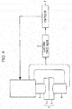
- Fig. 4 is an illustration showing the structure of a resistance spot welding device according to the embodiment of the present invention.
- This device is a device for resistance spot welding in which a sheet set 3 including at least two overlapping steel sheets (1 and 2) is held between a pair of electrodes and welded by applying an electric current under pressure.
- This device includes a pair of electrodes (a lower electrode 4 and an upper electrode 5), an electrode force gauge 6, and a controller 7.
- the electrode force gauge 6 measures an electrode force F applied by the electrodes 4 and 5 (hereinafter referred to simply as the electrode force F) and outputs the measured electrode force F to the controller 7.
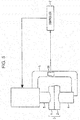
- the electrode force gauge 6 may be a strain gauge 61 that measures the strain of a gun arm 8 to which the lower electrode 4 and the upper electrode 5 are mounted, as shown in Fig. 5 .
- a strain approximately proportional to the electrode force F is generated in the gun arm 8. This strain is measured by the strain gauge 61 and converted to the electrode force F, and the electrode force F can thereby be determined.
- the electrode force gauge 6 used may be, in addition to the strain gauge 61, a load cell capable of measuring the electrode force F, and the strain gauge 61 and the load cell may be used in combination.
- the controller 7 controls the electrode force F according to the electrode force F measured by the electrode force gauge 6 as follows. Specifically, when the electrode force F after an electric current supply is started changes from an initial electrode force Fi to an electrode force F h (1) represented by formula (1) while a lapse from the start of the electric current supply is between 20 ms and 80 ms inclusive, the controller 7 starts a suspension of the electric current supply for from 20 ms to 60 ms inclusive. 1.03 ⁇ Fi ⁇ F h 1 ⁇ 1.15 ⁇ Fi
- F h (1) is less than 1.03 ⁇ F i , a region in the vicinity of the nugget is not pressurized sufficiently, and the probability of the occurrence of expulsion becomes high. If F h (1) is larger than 1.15 ⁇ F i , the growth of the nugget is inhibited.
- the controller 7 controls the electric current supply such that the electric current supply is resumed when the electrode force F reaches an electrode force F c (1) represented by formula (2). 1.01 ⁇ Fi ⁇ F c 1 ⁇ 0.99 ⁇ F h 1
- F c (1) is less than 1.01 ⁇ Fi, cooling proceeds, and therefore the effects of the subsequent heating become small. If F c (1) is larger than 0.99 ⁇ F h (1) , the temperature of the nugget is high, and therefore the possibility of the occurrence of expulsion when the electric current supply is resumed increases.
- the initial electrode force Fi used is the average electrode force in the first cycle (20 ms) after the start of the supply.
- the electrode force immediately after the start of the electric current supply is approximately the same as a set electrode force (designated electrode force) of a servo gun, and therefore the designated electrode force may be used as the initial electrode force Fi.
- the average electrode force in a period from 0 ms to 20 ms after the start of the electric current supply may be used as the initial electrode force Fi.
- the controller 7 controls the electric current supply such that, after the suspension of the electric current supply, the electric current supply for from 20 ms to 80 ms inclusive and the suspension of the electric current supply for from 20 ms to 60 ms inclusive are repeated at least once.
- F h (N) is less than 1.04 ⁇ F c (N-1) , the probability of the occurrence of expulsion becomes high. If F h (N) is larger than 1.15 ⁇ F c (N-1) , the growth of the nugget is inhibited.
- the controller 7 controls the electric current supply such that, when the electrode force F reaches an electrode force F c (N) represented by formula (4), the electric current supply is resumed.
- N is a natural number of 2 or more.
- F c (N) is less than F c (N-1) , cooling proceeds, and therefore the effects of the subsequent heating become small. If F c (N) is larger than 0.99 ⁇ F h (N) , the possibility of the occurrence of expulsion when the electric current supply is resumed increases.
- the period of the last repetition of the electric current supply is preferably from 100 ms to 300 ms inclusive.
- the last repetition of the electric current supply means the (N+1)th repetition of the electric current supply. If the period of the last repetition is less than 100 ms, the formation of the nugget is insufficient. If the period of the last repetition of the electric current supply exceeds 300 ms, the workability deteriorates, and the contribution of the electric current supply to the formation of the nugget is small.
- the period of the last repetition of the electric current supply may be selected optimally within the above range according to the period required for the first electric current supply and the subsequent repetitions of the electric current supply and the suspension of the electric current supply.
- the resistance spot welding device is not limited to the structures shown in Figs. 4 and 5 . It is only necessary for the resistance spot welding device according to the present invention to include: the vertical pair of electrodes which holds parts to be welded and through which the electrode force and the electric current are applied; and the welding current controller that can control the welding current freely during welding. No particular limitation is imposed on the pressure mechanism (such as an air cylinder or a servo motor), the current control mechanism (such as an AC or DC current control mechanism), the type (a stationary type, a robot gun, etc.), etc.
- the pressure mechanism such as an air cylinder or a servo motor
- the current control mechanism such as an AC or DC current control mechanism
- the type a stationary type, a robot gun, etc.
- the present invention is applied to a welding device for a sheet set of a plurality of sheets including a galvanized steel sheet or a high-strength steel sheet.
- Galvanized steel sheets and high-strength steel sheets are more likely to cause expulsion due to a sheet gap than ordinary steel sheets.
- the present invention has the effect of preventing the occurrence of expulsion. It is more effective to apply the invention to welding of a sheet set including at least one sheet selected from those steel sheets.
- At least one of the steel sheets included in the sheet set to be welded is a high-strength steel sheet having a tensile strength of 980 MPa or more and containing components including 0.15 ⁇ C ⁇ 0.30 (%by mass), 1.9 ⁇ Mn ⁇ 5.0 (%by mass), and 0.2 ⁇ Si ⁇ 2.0 (%by mass), the occurrence of expulsion is prevented, and a nugget with a large diameter can be formed.
- the galvanized steel sheet is a steel sheet including a coating layer containing Zn as a main component and encompasses any conventionally known galvanized layer.
- the coating layer containing Zn as a main component include a hot-dip galvanized layer, an electrogalvanized layer, an Al coating layer, a Zn-Al coating layer, and a Zn-Ni layer.
- the electrode force is measured as described above, and the electric current is supplied and suspended while the electrode force is controlled appropriately according to the measured electrode force during the electric current supply. Thereby, the occurrence of expulsion is prevented, and a large nugget can be formed. Therefore, even when work disturbances such as a sheet gap are present, the diameter of the nugget can be ensured stably.
- the device shown in Fig. 5 was used to produce a resistance spot-welded joint using a sheet set 3 including two overlapping hot-dip galvannealed steel sheets (a lower steel sheet 1 and an upper steel sheet 2).
- the device used in the Examples was a welding device of the C gun type including a servo motor used to press the electrodes.
- the power source used was a DC power source.
- the electrodes 4 and 5 used were DR type electrodes made of alumina-dispersed copper and having a tip radius of curvature R of 40 mm and a tip diameter of 8 mm.
- the test pieces used were high-strength steel sheets having a 980 MPa-class tensile strength and sheet thicknesses of 0.8 to 2.6 mm and a high-strength steel sheet having a 1,470 MPa-class tensile strength and a sheet thickness of 2.0 mm. Two steel sheets of the same type and with the same thickness were stacked and welded.
- the electrode force during the electric current supply was measured using the strain gauge 61 attached to the C gun.
- the electric current supplied was changed such that the measured electrode force was adjusted to a prescribed value.
- Table 1 shows the results of studies on the occurrence of expulsion during welding and the diameter of the nugget.
- the diameter of the nugget was evaluated based on the structure of an etched cross section as follows. Let the sheet thickness be t (mm). Then a "Good” rating was given when the diameter of the nugget was equal to or larger than 5.5 ⁇ t. A “Poor” rating was given when the diameter of the nugget was less than 5.5 ⁇ t. Specifically, a nugget diameter equal to or larger than 5.5 ⁇ t was set to be an appropriate diameter.
- I 1 (kA) is the current value in the first electric current supply
- T 1 (ms) is the current supply time in the first electric current supply
- F h (1) /F i is the ratio of the electrode force F h (1) to the initial electrode force Fi
- Tc 1 (ms) is the first suspension time
- F c (1) /F i is the ratio of the electrode force F c (1) to the initial electrode force Fi
- F c (1) /F h (1) is the ratio of the electrode force F c (1) at which the electric current supply is resumed to the electrode force F h (1) at which the suspension of the electric current supply is started.
- I 2 (kA) is the current value in the second electric current supply
- T 2 (ms) is the current supply time in the second electric current supply.
- a servo motor pressurizing-type resistance welding device attached to a C gun and including a DC power source was used to perform resistance spot welding on a sheet set including three overlapping hot-dip galvannealed steel sheets to thereby produce a resistance spot-welded joint.
- the electrodes 4 and 5 used were DR type electrodes made of alumina-dispersed copper and having a tip radius of curvature R of 40 mm and a tip diameter of 8 mm.
- the test pieces used were 980 MPa class high-strength steel sheets having sheet thicknesses of 0.8 to 2.3 mm and a 1,800 MPa class high-strength steel sheet having a sheet thickness of 1.2 mm. Three steel sheets of the same type and with the same thickness were stacked and welded.
- the electrode force during the electric current supply was measured using a strain gauge attached to the C gun.
- the electrode force was changed such that the measured electrode force was adjusted to a prescribed value.
- Table 2 shows the results of studies on the occurrence of expulsion during welding and the diameter of the nugget.
- the diameter of the nugget was evaluated based on the structure of an etched cross section as follows. Let the sheet thickness be t (mm). Then a "Good” rating was given when the diameter of the nugget was equal to or larger than 5.5 ⁇ t. A “Poor” rating was given when the diameter of the nugget was less than 5.5 ⁇ t. Specifically, a nugget diameter equal to or larger than 5.5 ⁇ t was set to be an appropriate diameter.
- I 1 (kA) is the current value in the first electric current supply
- T 1 (ms) is the current supply time in the first electric current supply
- F h (1) /F i is the ratio of the electrode force F h (1) to the initial electrode force Fi
- Tc 1 (ms) is the first suspension time
- F c (1) /F i . is the ratio of the electrode force F c (1) to the initial electrode force Fi
- F c (1) /F h (1) is the ratio of the electrode force at which the electric current supply is resumed to the electrode force at which the suspension of the electric current supply is started.
- F h (2) /F c (1) is the ratio of the electrode force at which, after the second electric current supply, the suspension of the electric current supply is started to the electrode force immediately after the first suspension.
- F c (2) /F c (1) is the ratio of the electrode force immediately after the second suspension to the electrode force immediately after the first suspension
- F c (2) /F h (2) is the ratio of the electrode force immediately after the second suspension to the electrode force at which, after the second electric current supply, the suspension of the electric current supply is started.
- I 2 (kA) and I 3 (kA) are the current values in the second and third electric current supplies, respectively, T 2 (ms) and T 3 (ms) are the current supply times in the second and third electric current supplies, respectively, and Tc 2 (ms) is the second suspension time.
Landscapes
- Engineering & Computer Science (AREA)
- Mechanical Engineering (AREA)
- Resistance Welding (AREA)
Applications Claiming Priority (3)
| Application Number | Priority Date | Filing Date | Title |
|---|---|---|---|
| JP2015043053 | 2015-03-05 | ||
| JP2015071650 | 2015-03-31 | ||
| PCT/JP2016/001174 WO2016139952A1 (ja) | 2015-03-05 | 2016-03-03 | 抵抗スポット溶接装置 |
Publications (3)
| Publication Number | Publication Date |
|---|---|
| EP3266554A1 true EP3266554A1 (de) | 2018-01-10 |
| EP3266554A4 EP3266554A4 (de) | 2018-03-14 |
| EP3266554B1 EP3266554B1 (de) | 2021-08-11 |
Family
ID=56849340
Family Applications (1)
| Application Number | Title | Priority Date | Filing Date |
|---|---|---|---|
| EP16758648.6A Active EP3266554B1 (de) | 2015-03-05 | 2016-03-03 | Widerstandspunktschweissvorrichtung |
Country Status (7)
| Country | Link |
|---|---|
| US (1) | US10722972B2 (de) |
| EP (1) | EP3266554B1 (de) |
| JP (1) | JP6079934B2 (de) |
| KR (1) | KR101946307B1 (de) |
| CN (1) | CN107405715B (de) |
| MX (1) | MX394290B (de) |
| WO (1) | WO2016139952A1 (de) |
Cited By (3)
| Publication number | Priority date | Publication date | Assignee | Title |
|---|---|---|---|---|
| WO2023002269A1 (en) * | 2021-07-23 | 2023-01-26 | Arcelormittal | A welding method |
| RU2826435C2 (ru) * | 2021-07-23 | 2024-09-10 | Арселормиттал | Способ сварки |
| EP4450938A1 (de) * | 2023-04-18 | 2024-10-23 | Diakont S.r.l. | Dehnungsmesser |
Families Citing this family (8)
| Publication number | Priority date | Publication date | Assignee | Title |
|---|---|---|---|---|
| EP3266553B1 (de) * | 2015-03-05 | 2021-06-30 | JFE Steel Corporation | Widerstandspunktschweissverfahren |
| JP6339292B2 (ja) * | 2015-06-26 | 2018-06-06 | 本田技研工業株式会社 | スポット溶接方法及びその装置 |
| JP2020171942A (ja) * | 2019-04-11 | 2020-10-22 | トヨタ自動車株式会社 | 抵抗スポット溶接装置 |
| JP7568921B2 (ja) * | 2021-01-04 | 2024-10-17 | 日本製鉄株式会社 | 抵抗スポット溶接継手の製造方法、及び抵抗スポット溶接装置 |
| JP7468418B2 (ja) * | 2021-03-18 | 2024-04-16 | トヨタ自動車株式会社 | 溶着判定方法およびスポット溶接装置 |
| CN119604382A (zh) | 2022-08-04 | 2025-03-11 | 日本制铁株式会社 | 点焊接头的制造方法及点焊接头 |
| JP7662005B2 (ja) * | 2022-09-28 | 2025-04-15 | Jfeスチール株式会社 | 抵抗スポット溶接方法 |
| KR20250009905A (ko) | 2023-07-11 | 2025-01-20 | 이동현 | 프리스트레스 보강재를 이용한 자립식 흙막이 가시설 |
Family Cites Families (31)
| Publication number | Priority date | Publication date | Assignee | Title |
|---|---|---|---|---|
| JPS59185581A (ja) * | 1983-04-07 | 1984-10-22 | フオルクスウア−ゲンウエルク・アクチエンゲゼルシヤフト | 抵抗スポツト溶接方法及び装置 |
| US4694135A (en) * | 1986-07-09 | 1987-09-15 | General Motors Corporation | Method and apparatus for monitoring and controlling resistance spot welding |
| JPH1058157A (ja) * | 1996-06-13 | 1998-03-03 | Kawasaki Heavy Ind Ltd | スポット溶接の制御方法および装置 |
| JP3588668B2 (ja) * | 1997-08-27 | 2004-11-17 | 日産自動車株式会社 | スポット溶接におけるナゲット径の推定方法 |
| JP3670842B2 (ja) * | 1998-05-25 | 2005-07-13 | 関東自動車工業株式会社 | スポット溶接装置 |
| US6515251B1 (en) * | 2000-10-31 | 2003-02-04 | Steelcase Development Corporation | Welding system and method |
| JP3849539B2 (ja) | 2002-02-19 | 2006-11-22 | Jfeスチール株式会社 | 高張力亜鉛系めっき鋼板のスポット溶接方法 |
| AT413504B (de) | 2002-07-03 | 2006-03-15 | Fronius Int Gmbh | Elektrodenschutzeinrichtung |
| JP3922263B2 (ja) | 2004-03-17 | 2007-05-30 | Jfeスチール株式会社 | 抵抗スポット溶接継手の製造方法 |
| JP2007321182A (ja) * | 2006-05-31 | 2007-12-13 | Nisshin Steel Co Ltd | 衝撃吸収能の大きな自動車部材 |
| JP4728926B2 (ja) | 2006-10-16 | 2011-07-20 | 新日本製鐵株式会社 | 重ね抵抗スポット溶接方法 |
| JP2008229720A (ja) * | 2007-02-22 | 2008-10-02 | Kobe Steel Ltd | 引張強度に優れた高張力鋼板スポット溶接継手、それを有する自動車部品、および高張力鋼板のスポット溶接方法 |
| JP5045238B2 (ja) | 2007-05-23 | 2012-10-10 | Jfeスチール株式会社 | 抵抗スポット溶接方法 |
| CN102227283B (zh) | 2008-09-30 | 2013-11-13 | 高周波热炼株式会社 | 金属构件的焊接装置以及金属构件的焊接方法 |
| JP5168204B2 (ja) | 2008-10-08 | 2013-03-21 | 新日鐵住金株式会社 | 鋼板のスポット溶接方法 |
| JP5201116B2 (ja) * | 2008-10-16 | 2013-06-05 | Jfeスチール株式会社 | 高強度鋼板の抵抗スポット溶接方法 |
| JP5415896B2 (ja) | 2009-01-29 | 2014-02-12 | Jfeスチール株式会社 | インダイレクトスポット溶接方法 |
| US8962149B2 (en) | 2009-08-31 | 2015-02-24 | Nippon Steel & Sumitomo Metal Corporation | Spot welded joint |
| JP2011152574A (ja) | 2010-01-28 | 2011-08-11 | Honda Motor Co Ltd | 抵抗溶接方法 |
| JP5392142B2 (ja) | 2010-02-22 | 2014-01-22 | 新日鐵住金株式会社 | 合金化アルミめっき鋼板またはアルミ合金層を有するプレス部品のスポット溶接方法 |
| JP5149355B2 (ja) | 2010-09-08 | 2013-02-20 | 富士重工業株式会社 | スポット溶接方法及びスポット溶接装置 |
| JP5740959B2 (ja) * | 2010-12-15 | 2015-07-01 | 日産自動車株式会社 | 接合方法および接合装置 |
| JP5549618B2 (ja) * | 2011-02-15 | 2014-07-16 | 新日鐵住金株式会社 | 引張強度980MPa以上のスポット溶接用高強度鋼板 |
| WO2012168564A1 (fr) | 2011-06-07 | 2012-12-13 | Arcelormittal Investigación Y Desarrollo Sl | Tôle d'acier laminée à froid et revêtue de zinc ou d'alliage de zinc, procédé de fabrication et utilisation d'une telle tôle |
| JP5498463B2 (ja) | 2011-10-13 | 2014-05-21 | 富士重工業株式会社 | スポット溶接装置の加圧制御方法 |
| JP5333560B2 (ja) * | 2011-10-18 | 2013-11-06 | Jfeスチール株式会社 | 高張力鋼板の抵抗スポット溶接方法及び抵抗スポット溶接継手 |
| CN102581459B (zh) | 2012-03-07 | 2014-06-25 | 上海交通大学 | 一种不等厚超高强热成形钢板与低碳钢板电阻焊方法 |
| DE102012025200A1 (de) | 2012-12-27 | 2014-07-03 | Robert Bosch Gmbh | Schweißverfahren zum Verschweißen von Aluminium |
| JP6001478B2 (ja) | 2013-03-19 | 2016-10-05 | 株式会社神戸製鋼所 | スポット溶接継手 |
| MX367552B (es) | 2013-07-11 | 2019-08-27 | Nippon Steel Corp | Método de soldadura de puntos por resistencia. |
| EP3266553B1 (de) * | 2015-03-05 | 2021-06-30 | JFE Steel Corporation | Widerstandspunktschweissverfahren |
-
2016
- 2016-03-03 EP EP16758648.6A patent/EP3266554B1/de active Active
- 2016-03-03 JP JP2016537581A patent/JP6079934B2/ja active Active
- 2016-03-03 KR KR1020177024489A patent/KR101946307B1/ko active Active
- 2016-03-03 MX MX2017011319A patent/MX394290B/es unknown
- 2016-03-03 CN CN201680013283.0A patent/CN107405715B/zh active Active
- 2016-03-03 WO PCT/JP2016/001174 patent/WO2016139952A1/ja not_active Ceased
- 2016-03-03 US US15/555,135 patent/US10722972B2/en active Active
Cited By (4)
| Publication number | Priority date | Publication date | Assignee | Title |
|---|---|---|---|---|
| WO2023002269A1 (en) * | 2021-07-23 | 2023-01-26 | Arcelormittal | A welding method |
| WO2023002239A1 (en) * | 2021-07-23 | 2023-01-26 | Arcelormittal | A welding method |
| RU2826435C2 (ru) * | 2021-07-23 | 2024-09-10 | Арселормиттал | Способ сварки |
| EP4450938A1 (de) * | 2023-04-18 | 2024-10-23 | Diakont S.r.l. | Dehnungsmesser |
Also Published As
| Publication number | Publication date |
|---|---|
| WO2016139952A1 (ja) | 2016-09-09 |
| US10722972B2 (en) | 2020-07-28 |
| EP3266554A4 (de) | 2018-03-14 |
| KR101946307B1 (ko) | 2019-02-11 |
| US20180043461A1 (en) | 2018-02-15 |
| JPWO2016139952A1 (ja) | 2017-04-27 |
| JP6079934B2 (ja) | 2017-02-15 |
| EP3266554B1 (de) | 2021-08-11 |
| CN107405715B (zh) | 2019-10-08 |
| KR20170109045A (ko) | 2017-09-27 |
| CN107405715A (zh) | 2017-11-28 |
| MX2017011319A (es) | 2017-12-07 |
| MX394290B (es) | 2025-03-04 |
Similar Documents
| Publication | Publication Date | Title |
|---|---|---|
| EP3266554B1 (de) | Widerstandspunktschweissvorrichtung | |
| EP3266553B1 (de) | Widerstandspunktschweissverfahren | |
| EP2783782B1 (de) | Widerstandspunktschweissverbindung | |
| US11298773B2 (en) | Resistance spot welding method | |
| EP3391988A1 (de) | Widerstandspunktschweissverfahren und verfahren zur herstellung eines geschweissten elements | |
| CN105358284A (zh) | 电阻点焊方法 | |
| US20200361021A1 (en) | Method for production of resistance spot-welded joint | |
| EP4393628A1 (de) | Widerstandspunktgeschweisstes element und widerstandspunktschweissverfahren dafür | |
| EP3342524B1 (de) | Widerstandspunktschweissverfahren und verfahren zur herstellung eines geschweissten elements | |
| JP6160581B2 (ja) | 抵抗スポット溶接方法 | |
| EP4563272A1 (de) | Geschweisstes element und verfahren zur herstellung davon | |
| EP3995246B1 (de) | Verfahren zur herstellung einer widerstandpunktschweissverbindung | |
| EP4484045B1 (de) | Schweissverbindung, schweissbauteil, verfahren zu dessen herstellung und widerstandspunktschweissverfahren | |
| EP4494800A1 (de) | Widerstandspunktschweissverfahren | |
| EP4353394A1 (de) | Widerstandspunktschweissverfahren | |
| EP4563273A1 (de) | Geschweisstes element und verfahren zur herstellung davon | |
| EP4484044A1 (de) | Schweissverbindung, schweisselement, verfahren zur herstellung davon und verfahren zum widerstandspunktschweissen | |
| WO2020217332A1 (ja) | 抵抗スポット溶接方法、抵抗スポット溶接継手の製造方法 |
Legal Events
| Date | Code | Title | Description |
|---|---|---|---|
| STAA | Information on the status of an ep patent application or granted ep patent |
Free format text: STATUS: THE INTERNATIONAL PUBLICATION HAS BEEN MADE |
|
| PUAI | Public reference made under article 153(3) epc to a published international application that has entered the european phase |
Free format text: ORIGINAL CODE: 0009012 |
|
| STAA | Information on the status of an ep patent application or granted ep patent |
Free format text: STATUS: REQUEST FOR EXAMINATION WAS MADE |
|
| 17P | Request for examination filed |
Effective date: 20170814 |
|
| AK | Designated contracting states |
Kind code of ref document: A1 Designated state(s): AL AT BE BG CH CY CZ DE DK EE ES FI FR GB GR HR HU IE IS IT LI LT LU LV MC MK MT NL NO PL PT RO RS SE SI SK SM TR |
|
| AX | Request for extension of the european patent |
Extension state: BA ME |
|
| A4 | Supplementary search report drawn up and despatched |
Effective date: 20180214 |
|
| RIC1 | Information provided on ipc code assigned before grant |
Ipc: B23K 103/04 20060101ALN20180208BHEP Ipc: B23K 11/16 20060101ALI20180208BHEP Ipc: B23K 11/25 20060101ALI20180208BHEP Ipc: B23K 101/00 20060101ALN20180208BHEP Ipc: B23K 11/11 20060101AFI20180208BHEP |
|
| DAV | Request for validation of the european patent (deleted) | ||
| DAX | Request for extension of the european patent (deleted) | ||
| GRAP | Despatch of communication of intention to grant a patent |
Free format text: ORIGINAL CODE: EPIDOSNIGR1 |
|
| STAA | Information on the status of an ep patent application or granted ep patent |
Free format text: STATUS: GRANT OF PATENT IS INTENDED |
|
| RIC1 | Information provided on ipc code assigned before grant |
Ipc: B23K 11/16 20060101ALI20201023BHEP Ipc: B23K 101/00 20060101ALN20201023BHEP Ipc: B23K 103/04 20060101ALN20201023BHEP Ipc: B23K 11/25 20060101ALI20201023BHEP Ipc: B23K 11/11 20060101AFI20201023BHEP |
|
| INTG | Intention to grant announced |
Effective date: 20201202 |
|
| GRAJ | Information related to disapproval of communication of intention to grant by the applicant or resumption of examination proceedings by the epo deleted |
Free format text: ORIGINAL CODE: EPIDOSDIGR1 |
|
| STAA | Information on the status of an ep patent application or granted ep patent |
Free format text: STATUS: REQUEST FOR EXAMINATION WAS MADE |
|
| INTC | Intention to grant announced (deleted) | ||
| RIC1 | Information provided on ipc code assigned before grant |
Ipc: B23K 103/04 20060101ALN20210317BHEP Ipc: B23K 101/00 20060101ALN20210317BHEP Ipc: B23K 11/25 20060101ALI20210317BHEP Ipc: B23K 11/16 20060101ALI20210317BHEP Ipc: B23K 11/11 20060101AFI20210317BHEP |
|
| GRAP | Despatch of communication of intention to grant a patent |
Free format text: ORIGINAL CODE: EPIDOSNIGR1 |
|
| RIC1 | Information provided on ipc code assigned before grant |
Ipc: B23K 103/04 20060101ALN20210401BHEP Ipc: B23K 101/00 20060101ALN20210401BHEP Ipc: B23K 11/25 20060101ALI20210401BHEP Ipc: B23K 11/16 20060101ALI20210401BHEP Ipc: B23K 11/11 20060101AFI20210401BHEP |
|
| STAA | Information on the status of an ep patent application or granted ep patent |
Free format text: STATUS: GRANT OF PATENT IS INTENDED |
|
| INTG | Intention to grant announced |
Effective date: 20210506 |
|
| GRAS | Grant fee paid |
Free format text: ORIGINAL CODE: EPIDOSNIGR3 |
|
| GRAA | (expected) grant |
Free format text: ORIGINAL CODE: 0009210 |
|
| STAA | Information on the status of an ep patent application or granted ep patent |
Free format text: STATUS: THE PATENT HAS BEEN GRANTED |
|
| AK | Designated contracting states |
Kind code of ref document: B1 Designated state(s): AL AT BE BG CH CY CZ DE DK EE ES FI FR GB GR HR HU IE IS IT LI LT LU LV MC MK MT NL NO PL PT RO RS SE SI SK SM TR |
|
| REG | Reference to a national code |
Ref country code: CH Ref legal event code: EP |
|
| REG | Reference to a national code |
Ref country code: DE Ref legal event code: R096 Ref document number: 602016062024 Country of ref document: DE |
|
| REG | Reference to a national code |
Ref country code: IE Ref legal event code: FG4D Ref country code: AT Ref legal event code: REF Ref document number: 1418880 Country of ref document: AT Kind code of ref document: T Effective date: 20210915 |
|
| REG | Reference to a national code |
Ref country code: LT Ref legal event code: MG9D |
|
| REG | Reference to a national code |
Ref country code: NL Ref legal event code: MP Effective date: 20210811 |
|
| REG | Reference to a national code |
Ref country code: AT Ref legal event code: MK05 Ref document number: 1418880 Country of ref document: AT Kind code of ref document: T Effective date: 20210811 |
|
| PG25 | Lapsed in a contracting state [announced via postgrant information from national office to epo] |
Ref country code: RS Free format text: LAPSE BECAUSE OF FAILURE TO SUBMIT A TRANSLATION OF THE DESCRIPTION OR TO PAY THE FEE WITHIN THE PRESCRIBED TIME-LIMIT Effective date: 20210811 Ref country code: SE Free format text: LAPSE BECAUSE OF FAILURE TO SUBMIT A TRANSLATION OF THE DESCRIPTION OR TO PAY THE FEE WITHIN THE PRESCRIBED TIME-LIMIT Effective date: 20210811 Ref country code: NO Free format text: LAPSE BECAUSE OF FAILURE TO SUBMIT A TRANSLATION OF THE DESCRIPTION OR TO PAY THE FEE WITHIN THE PRESCRIBED TIME-LIMIT Effective date: 20211111 Ref country code: PT Free format text: LAPSE BECAUSE OF FAILURE TO SUBMIT A TRANSLATION OF THE DESCRIPTION OR TO PAY THE FEE WITHIN THE PRESCRIBED TIME-LIMIT Effective date: 20211213 Ref country code: HR Free format text: LAPSE BECAUSE OF FAILURE TO SUBMIT A TRANSLATION OF THE DESCRIPTION OR TO PAY THE FEE WITHIN THE PRESCRIBED TIME-LIMIT Effective date: 20210811 Ref country code: FI Free format text: LAPSE BECAUSE OF FAILURE TO SUBMIT A TRANSLATION OF THE DESCRIPTION OR TO PAY THE FEE WITHIN THE PRESCRIBED TIME-LIMIT Effective date: 20210811 Ref country code: ES Free format text: LAPSE BECAUSE OF FAILURE TO SUBMIT A TRANSLATION OF THE DESCRIPTION OR TO PAY THE FEE WITHIN THE PRESCRIBED TIME-LIMIT Effective date: 20210811 Ref country code: LT Free format text: LAPSE BECAUSE OF FAILURE TO SUBMIT A TRANSLATION OF THE DESCRIPTION OR TO PAY THE FEE WITHIN THE PRESCRIBED TIME-LIMIT Effective date: 20210811 Ref country code: AT Free format text: LAPSE BECAUSE OF FAILURE TO SUBMIT A TRANSLATION OF THE DESCRIPTION OR TO PAY THE FEE WITHIN THE PRESCRIBED TIME-LIMIT Effective date: 20210811 Ref country code: BG Free format text: LAPSE BECAUSE OF FAILURE TO SUBMIT A TRANSLATION OF THE DESCRIPTION OR TO PAY THE FEE WITHIN THE PRESCRIBED TIME-LIMIT Effective date: 20211111 |
|
| PG25 | Lapsed in a contracting state [announced via postgrant information from national office to epo] |
Ref country code: PL Free format text: LAPSE BECAUSE OF FAILURE TO SUBMIT A TRANSLATION OF THE DESCRIPTION OR TO PAY THE FEE WITHIN THE PRESCRIBED TIME-LIMIT Effective date: 20210811 Ref country code: LV Free format text: LAPSE BECAUSE OF FAILURE TO SUBMIT A TRANSLATION OF THE DESCRIPTION OR TO PAY THE FEE WITHIN THE PRESCRIBED TIME-LIMIT Effective date: 20210811 Ref country code: GR Free format text: LAPSE BECAUSE OF FAILURE TO SUBMIT A TRANSLATION OF THE DESCRIPTION OR TO PAY THE FEE WITHIN THE PRESCRIBED TIME-LIMIT Effective date: 20211112 |
|
| PG25 | Lapsed in a contracting state [announced via postgrant information from national office to epo] |
Ref country code: NL Free format text: LAPSE BECAUSE OF FAILURE TO SUBMIT A TRANSLATION OF THE DESCRIPTION OR TO PAY THE FEE WITHIN THE PRESCRIBED TIME-LIMIT Effective date: 20210811 |
|
| PG25 | Lapsed in a contracting state [announced via postgrant information from national office to epo] |
Ref country code: DK Free format text: LAPSE BECAUSE OF FAILURE TO SUBMIT A TRANSLATION OF THE DESCRIPTION OR TO PAY THE FEE WITHIN THE PRESCRIBED TIME-LIMIT Effective date: 20210811 |
|
| REG | Reference to a national code |
Ref country code: DE Ref legal event code: R097 Ref document number: 602016062024 Country of ref document: DE |
|
| PG25 | Lapsed in a contracting state [announced via postgrant information from national office to epo] |
Ref country code: SM Free format text: LAPSE BECAUSE OF FAILURE TO SUBMIT A TRANSLATION OF THE DESCRIPTION OR TO PAY THE FEE WITHIN THE PRESCRIBED TIME-LIMIT Effective date: 20210811 Ref country code: SK Free format text: LAPSE BECAUSE OF FAILURE TO SUBMIT A TRANSLATION OF THE DESCRIPTION OR TO PAY THE FEE WITHIN THE PRESCRIBED TIME-LIMIT Effective date: 20210811 Ref country code: RO Free format text: LAPSE BECAUSE OF FAILURE TO SUBMIT A TRANSLATION OF THE DESCRIPTION OR TO PAY THE FEE WITHIN THE PRESCRIBED TIME-LIMIT Effective date: 20210811 Ref country code: EE Free format text: LAPSE BECAUSE OF FAILURE TO SUBMIT A TRANSLATION OF THE DESCRIPTION OR TO PAY THE FEE WITHIN THE PRESCRIBED TIME-LIMIT Effective date: 20210811 Ref country code: CZ Free format text: LAPSE BECAUSE OF FAILURE TO SUBMIT A TRANSLATION OF THE DESCRIPTION OR TO PAY THE FEE WITHIN THE PRESCRIBED TIME-LIMIT Effective date: 20210811 Ref country code: AL Free format text: LAPSE BECAUSE OF FAILURE TO SUBMIT A TRANSLATION OF THE DESCRIPTION OR TO PAY THE FEE WITHIN THE PRESCRIBED TIME-LIMIT Effective date: 20210811 |
|
| PLBE | No opposition filed within time limit |
Free format text: ORIGINAL CODE: 0009261 |
|
| STAA | Information on the status of an ep patent application or granted ep patent |
Free format text: STATUS: NO OPPOSITION FILED WITHIN TIME LIMIT |
|
| 26N | No opposition filed |
Effective date: 20220512 |
|
| PG25 | Lapsed in a contracting state [announced via postgrant information from national office to epo] |
Ref country code: IT Free format text: LAPSE BECAUSE OF FAILURE TO SUBMIT A TRANSLATION OF THE DESCRIPTION OR TO PAY THE FEE WITHIN THE PRESCRIBED TIME-LIMIT Effective date: 20210811 |
|
| PG25 | Lapsed in a contracting state [announced via postgrant information from national office to epo] |
Ref country code: SI Free format text: LAPSE BECAUSE OF FAILURE TO SUBMIT A TRANSLATION OF THE DESCRIPTION OR TO PAY THE FEE WITHIN THE PRESCRIBED TIME-LIMIT Effective date: 20210811 |
|
| PG25 | Lapsed in a contracting state [announced via postgrant information from national office to epo] |
Ref country code: MC Free format text: LAPSE BECAUSE OF FAILURE TO SUBMIT A TRANSLATION OF THE DESCRIPTION OR TO PAY THE FEE WITHIN THE PRESCRIBED TIME-LIMIT Effective date: 20210811 |
|
| REG | Reference to a national code |
Ref country code: CH Ref legal event code: PL |
|
| REG | Reference to a national code |
Ref country code: BE Ref legal event code: MM Effective date: 20220331 |
|
| PG25 | Lapsed in a contracting state [announced via postgrant information from national office to epo] |
Ref country code: LU Free format text: LAPSE BECAUSE OF NON-PAYMENT OF DUE FEES Effective date: 20220303 Ref country code: LI Free format text: LAPSE BECAUSE OF NON-PAYMENT OF DUE FEES Effective date: 20220331 Ref country code: IE Free format text: LAPSE BECAUSE OF NON-PAYMENT OF DUE FEES Effective date: 20220303 Ref country code: CH Free format text: LAPSE BECAUSE OF NON-PAYMENT OF DUE FEES Effective date: 20220331 |
|
| PG25 | Lapsed in a contracting state [announced via postgrant information from national office to epo] |
Ref country code: BE Free format text: LAPSE BECAUSE OF NON-PAYMENT OF DUE FEES Effective date: 20220331 |
|
| PG25 | Lapsed in a contracting state [announced via postgrant information from national office to epo] |
Ref country code: HU Free format text: LAPSE BECAUSE OF FAILURE TO SUBMIT A TRANSLATION OF THE DESCRIPTION OR TO PAY THE FEE WITHIN THE PRESCRIBED TIME-LIMIT; INVALID AB INITIO Effective date: 20160303 |
|
| PG25 | Lapsed in a contracting state [announced via postgrant information from national office to epo] |
Ref country code: MK Free format text: LAPSE BECAUSE OF FAILURE TO SUBMIT A TRANSLATION OF THE DESCRIPTION OR TO PAY THE FEE WITHIN THE PRESCRIBED TIME-LIMIT Effective date: 20210811 Ref country code: CY Free format text: LAPSE BECAUSE OF FAILURE TO SUBMIT A TRANSLATION OF THE DESCRIPTION OR TO PAY THE FEE WITHIN THE PRESCRIBED TIME-LIMIT Effective date: 20210811 |
|
| PGFP | Annual fee paid to national office [announced via postgrant information from national office to epo] |
Ref country code: GB Payment date: 20240201 Year of fee payment: 9 |
|
| PG25 | Lapsed in a contracting state [announced via postgrant information from national office to epo] |
Ref country code: TR Free format text: LAPSE BECAUSE OF FAILURE TO SUBMIT A TRANSLATION OF THE DESCRIPTION OR TO PAY THE FEE WITHIN THE PRESCRIBED TIME-LIMIT Effective date: 20210811 |
|
| PG25 | Lapsed in a contracting state [announced via postgrant information from national office to epo] |
Ref country code: MT Free format text: LAPSE BECAUSE OF FAILURE TO SUBMIT A TRANSLATION OF THE DESCRIPTION OR TO PAY THE FEE WITHIN THE PRESCRIBED TIME-LIMIT Effective date: 20210811 |
|
| GBPC | Gb: european patent ceased through non-payment of renewal fee |
Effective date: 20250303 |
|
| PG25 | Lapsed in a contracting state [announced via postgrant information from national office to epo] |
Ref country code: GB Free format text: LAPSE BECAUSE OF NON-PAYMENT OF DUE FEES Effective date: 20250303 |
|
| PGFP | Annual fee paid to national office [announced via postgrant information from national office to epo] |
Ref country code: DE Payment date: 20260128 Year of fee payment: 11 |
|
| PGFP | Annual fee paid to national office [announced via postgrant information from national office to epo] |
Ref country code: FR Payment date: 20260209 Year of fee payment: 11 |