EP3266030B1 - Breaking-pole control system with override and breaker device - Google Patents
Breaking-pole control system with override and breaker device Download PDFInfo
- Publication number
- EP3266030B1 EP3266030B1 EP16710262.3A EP16710262A EP3266030B1 EP 3266030 B1 EP3266030 B1 EP 3266030B1 EP 16710262 A EP16710262 A EP 16710262A EP 3266030 B1 EP3266030 B1 EP 3266030B1
- Authority
- EP
- European Patent Office
- Prior art keywords
- carriage
- poles
- control handle
- breaking
- breaker
- Prior art date
- Legal status (The legal status is an assumption and is not a legal conclusion. Google has not performed a legal analysis and makes no representation as to the accuracy of the status listed.)
- Active
Links
- 238000009825 accumulation Methods 0.000 claims description 53
- 230000007935 neutral effect Effects 0.000 claims description 11
- 230000000903 blocking effect Effects 0.000 claims description 9
- 238000006073 displacement reaction Methods 0.000 description 6
- 230000000694 effects Effects 0.000 description 5
- 238000003466 welding Methods 0.000 description 5
- 239000000470 constituent Substances 0.000 description 3
- 230000006835 compression Effects 0.000 description 2
- 238000007906 compression Methods 0.000 description 2
- 238000009434 installation Methods 0.000 description 2
- 238000010616 electrical installation Methods 0.000 description 1
- 238000002955 isolation Methods 0.000 description 1
- 230000000717 retained effect Effects 0.000 description 1
- 230000001960 triggered effect Effects 0.000 description 1
Images


Classifications
-
- H—ELECTRICITY
- H01—ELECTRIC ELEMENTS
- H01H—ELECTRIC SWITCHES; RELAYS; SELECTORS; EMERGENCY PROTECTIVE DEVICES
- H01H71/00—Details of the protective switches or relays covered by groups H01H73/00 - H01H83/00
- H01H71/10—Operating or release mechanisms
- H01H71/50—Manual reset mechanisms which may be also used for manual release
- H01H71/501—Means for breaking welded contacts; Indicating contact welding or other malfunction of the circuit breaker
-
- H—ELECTRICITY
- H01—ELECTRIC ELEMENTS
- H01H—ELECTRIC SWITCHES; RELAYS; SELECTORS; EMERGENCY PROTECTIVE DEVICES
- H01H71/00—Details of the protective switches or relays covered by groups H01H73/00 - H01H83/00
- H01H71/10—Operating or release mechanisms
- H01H71/50—Manual reset mechanisms which may be also used for manual release
- H01H71/52—Manual reset mechanisms which may be also used for manual release actuated by lever
-
- H—ELECTRICITY
- H01—ELECTRIC ELEMENTS
- H01H—ELECTRIC SWITCHES; RELAYS; SELECTORS; EMERGENCY PROTECTIVE DEVICES
- H01H9/00—Details of switching devices, not covered by groups H01H1/00 - H01H7/00
- H01H9/20—Interlocking, locking, or latching mechanisms
- H01H9/28—Interlocking, locking, or latching mechanisms for locking switch parts by a key or equivalent removable member
- H01H9/281—Interlocking, locking, or latching mechanisms for locking switch parts by a key or equivalent removable member making use of a padlock
- H01H9/282—Interlocking, locking, or latching mechanisms for locking switch parts by a key or equivalent removable member making use of a padlock and a separate part mounted or mountable on the switch assembly and movable between an unlocking position and a locking position where it can be secured by the padlock
-
- H—ELECTRICITY
- H01—ELECTRIC ELEMENTS
- H01H—ELECTRIC SWITCHES; RELAYS; SELECTORS; EMERGENCY PROTECTIVE DEVICES
- H01H9/00—Details of switching devices, not covered by groups H01H1/00 - H01H7/00
- H01H9/20—Interlocking, locking, or latching mechanisms
- H01H9/28—Interlocking, locking, or latching mechanisms for locking switch parts by a key or equivalent removable member
- H01H2009/288—Provisions relating to welded contacts
-
- H—ELECTRICITY
- H01—ELECTRIC ELEMENTS
- H01H—ELECTRIC SWITCHES; RELAYS; SELECTORS; EMERGENCY PROTECTIVE DEVICES
- H01H2235/00—Springs
- H01H2235/01—Spiral spring
-
- H—ELECTRICITY
- H01—ELECTRIC ELEMENTS
- H01H—ELECTRIC SWITCHES; RELAYS; SELECTORS; EMERGENCY PROTECTIVE DEVICES
- H01H3/00—Mechanisms for operating contacts
- H01H3/32—Driving mechanisms, i.e. for transmitting driving force to the contacts
- H01H3/40—Driving mechanisms, i.e. for transmitting driving force to the contacts using friction, toothed, or screw-and-nut gearing
-
- H—ELECTRICITY
- H01—ELECTRIC ELEMENTS
- H01H—ELECTRIC SWITCHES; RELAYS; SELECTORS; EMERGENCY PROTECTIVE DEVICES
- H01H3/00—Mechanisms for operating contacts
- H01H3/54—Mechanisms for coupling or uncoupling operating parts, driving mechanisms, or contacts
- H01H3/58—Mechanisms for coupling or uncoupling operating parts, driving mechanisms, or contacts using friction, toothed, or other mechanical clutch
-
- H—ELECTRICITY
- H01—ELECTRIC ELEMENTS
- H01H—ELECTRIC SWITCHES; RELAYS; SELECTORS; EMERGENCY PROTECTIVE DEVICES
- H01H71/00—Details of the protective switches or relays covered by groups H01H73/00 - H01H83/00
- H01H71/10—Operating or release mechanisms
- H01H71/50—Manual reset mechanisms which may be also used for manual release
- H01H71/56—Manual reset mechanisms which may be also used for manual release actuated by rotatable knob or wheel
-
- H—ELECTRICITY
- H01—ELECTRIC ELEMENTS
- H01H—ELECTRIC SWITCHES; RELAYS; SELECTORS; EMERGENCY PROTECTIVE DEVICES
- H01H83/00—Protective switches, e.g. circuit-breaking switches, or protective relays operated by abnormal electrical conditions otherwise than solely by excess current
- H01H83/12—Protective switches, e.g. circuit-breaking switches, or protective relays operated by abnormal electrical conditions otherwise than solely by excess current operated by voltage falling below a predetermined value, e.g. for no-volt protection
-
- H—ELECTRICITY
- H01—ELECTRIC ELEMENTS
- H01H—ELECTRIC SWITCHES; RELAYS; SELECTORS; EMERGENCY PROTECTIVE DEVICES
- H01H9/00—Details of switching devices, not covered by groups H01H1/00 - H01H7/00
- H01H9/20—Interlocking, locking, or latching mechanisms
- H01H9/26—Interlocking, locking, or latching mechanisms for interlocking two or more switches
Definitions
- the present invention relates to the general field of electrical switchgear and more particularly to systems for operating the break in such devices.
- the electric switchgear is equipped with a control system connected to the electric breaking poles from which the power cut is controlled.
- the control system represents the most important safety element of the installation because it ensures the level of performance and reliability of the electrical switchgear as well as the interface between a user and the electrical part of power the device or devices powered by electric current.
- the control system allows the user to switch the cutoff poles or poles from a closed position (establishment of the electric current), called the "closed position”, to an open position (cut-off of the electric current), called “position “cut-off”, and vice versa, by means of a control handle.
- the control system comprises a storage mechanism formed mainly of an internal carriage connected to the control handle and an external carriage connected to a control axis of the breaking poles, the internal carriage sliding in the external carriage .
- a spring is interposed between the two carriages so as to accumulate mechanical energy during movement of the internal carriage by the control handle and to restore this energy to the external carriage at the end of travel of the control handle in order to allow a quick and reliable opening or closing of the cutoff pole or poles.
- the external carriage of the control system which is connected to the poles by a control shaft, can remain blocked while the control handle has realized. the entire stroke between the closed position and the cut position.
- the control system is no longer usable in that the welding of one or more poles prevents the control of the opening of all the poles.
- EP 0 299 291 discloses a storage control system for one or more electric shutdown poles the system comprising: a storage mechanism comprising a movable control handle at least between a closed position and a cutoff position, and vice versa; a first link pivoting about a first point of rotation between a first position and a second position, and vice versa, by actuating the control handle of the accumulation mechanism between the off position and the closed position, and vice versa; a second connecting rod pivoting about an axis of rotation intended to be connected to one or more breaking poles, the second connecting rod being connected to the first connecting rod by a sliding connection so that the displacement of the first link between the first position and the second position, respectively between the second position and the first position, causes the pivoting of the second connecting rod about the axis of rotation between an open position of the cut-off pole (s) and a closing position of the at least one pole of cutoff, respectively between a closed position of the cutoff poles and an open position of the cutoff poles or poles.
- the object of the present invention is to propose a new design of a control system which makes it possible to force cut-off poles whose contacts are soldered.
- the triggering control system of the present invention makes it possible to detect a possible blockage (ie welding) of one or more cut-off poles connected to the control system. Indeed, if one or more breaking poles are welded, it is possible to detect it by a resistor in the control handle when it is actuated beyond the cutoff position. In addition, when a force greater than the locking force of the welded breaking poles or poles is applied to the control handle, the contacts of the pole or poles can be released, which allows the control system to return to its position. Normal position of cut.
- the internal carriage comprises at least one stop adapted to come into contact with the external carriage when the inner carriage is moved by the control handle towards the opening position of the cutoff pole or poles while the external carriage is locked in the closed position of the breaking poles so as to force the movement of the external carriage towards the switch position by means of the control handle.
- control system of the invention comprises a lockout device comprising a lockout element movable between a neutral position and a lockout position for locking the accumulation control system in the cutoff position and in that said padlocking device further comprises control means for locking the lockout element in the neutral position when the external carriage is locked in the closed position of the breaking poles while the control handle is moved in the breaking position.
- the system of the invention can be locked in its breaking position, and in a completely secure manner because it can not be locked if the external carriage is locked in the closed position of the breaking poles even if the control handle is moved to the cut position.
- the control system can not be locked if one or more cutoff poles are soldered in their closed position.
- control system of the invention comprises at least one rocker pawl movable between a high position when the external carriage is in the closed position of the breaking poles and a low position when said external carriage is in the open position of the breaking poles and in that the padlocking device comprises a locking element movable between a neutral position when the rocker pawl is in the low position and a blocking position when the rocker pawl is in the high position so as to lock the lockout element in the neutral position when the external carriage is locked in the closed position of the cutoff poles while the control handle is moved to the cutoff position.
- the locking element is thus able to test the position of the rocker pawl and to authorize the locking of the system in the cutoff position only if the pawl is in the low position, position indicating that the external carriage is in the position and therefore no break-off pole has been blocked in the closed position.
- the locking element is able to block the displacement of the control handle when said locking element is in the locking position. Thus, it further prevents any movement of the control handle.
- the lockout element comprises a tab having an accessible light when said lockout element is in the lockout position. It is thus possible to lock the system in the cutoff position by placing one or more padlocks in the light, which makes it possible to secure the intervention of one or more operators.
- the present invention also relates to an electric switchgear device comprising one or more electric breaking poles equipped with a movable bar, characterized in that said apparatus further comprises a storage control system according to the invention, a control shaft. cut connecting each movable bar of the cutoff poles or poles to the axis of rotation of the second link.
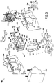
- the Figure 1A illustrates a switchgear 1 according to one embodiment of the invention.
- the apparatus 1 comprises a storage control system 100 according to one embodiment and a plurality of cut-off poles 10.
- the cut-off poles 10 correspond to cut-off devices such as fuse switches, switches or switch-disconnectors.
- each cut-off pole 10 is connected to the accumulation control system 100 by a cut-off shaft 101 which is secured, on the one hand, to a connecting rod of the system 100 described hereinafter in detail, and, on the other hand at each movable bar of the breaking poles corresponding here to a set of movable contacts 11, the shaft 101 constituting the axis of rotation of the movable contacts 11.
- the rotation of the shaft 101 which is controlled by the system 100 makes it possible to moving the movable contacts 11 of each breaking pole between an open position ( Figure 1A ) in which the movable contacts 11 are placed at a distance from the fixed contacts 13 of the switchgear ( Figure 1B ) and a closed position ( Figure 2A ) in which the movable contacts 11 are in contact with the fixed contacts 13 of the breaking poles ( Figure 2B ), and vice versa.
- control of the opening and closing of the breaking poles 10, and vice versa is carried out by means of a control handle 102 movable between a first position represented on the Figure 1A said "cut-off position" and which corresponds to the open position of the breaking poles 10 and a second position represented on the Figure 2A said "closed position” and which corresponds to the closing position of the breaking poles 10.
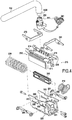
- the inner carriages 210 and outer 220 are slidably mounted relative to each other, the carriage guides 250 directing the relative sliding between the two carriages.
- the storage spring 230 is interposed between the two carriages. More specifically, the spring 230 is held on the spring guide 240 which is itself fixed on two fixing lugs 221 and 222 respectively present at both ends of the external carriage 220. At rest, the spring 230 extends between the two legs 221 and 222 as illustrated on the figure 9 .
- the inner carriage 210 comprises two pairs of bearing lugs 211 and 212 each respectively disposed on each side of the lugs 221 and 222 ( figures 4 , 5 and 6 ).
- the support lugs 211 and 212 are intended to abut on one end of the spring 230 to compress it during the displacement of the internal carriage in the external carriage during the opening operations and
- the internal carriage 210 comprises, in its upper part, rack teeth 213 which are intended to cooperate with the pinions 261 of the control pin 260.
- the control pin 260 also comprises a housing 262 for receiving the axis 1020 of the handle 102.
- the first pivoting rod 600 comprises an arm 610 pivotable about a first point of rotation P1 formed by an axis 611 which is retained by the trigger mechanism 300.
- the arm 610 further comprises at its upper end an axis 612 crimped on said upper end and intended to be engaged in a slot 201 formed in the outer carriage 220.
- the axis 612 is a second point of rotation P2 around which the arm of the rod 600 can rotate.
- the connecting rod 600 comprises a second arm 620 connected to the first arm 610 by a spar 630.
- the second arm is pivotable, on the one hand, around the point of rotation P1 and on the other hand, around the second point of P2 rotation, the arm 620 having an axis 622 crimped on its upper end and intended to be engaged with light 202 formed in the external carriage 220.
- the second pivoting rod 700 comprises a body 701 having a light 720 for receiving an end of the shaft 101 for controlling the opening and closing of the breaking poles 10.
- the light 720 includes slots 721 for cooperating with teeth 1010 present on the outer surface of the shaft 101 ( Figures 1B and 2B ).
- the center 722 of the light 720 coincides with the center 1011 of the shaft 101.
- the second link 700 further comprises a pin 710 present on the body 701 in a position offset from the position of the light 720.
- the pin 710 is intended to be engaged in an oblong groove 613 formed in the arm 610 of the rod 600 and to slide therein during the movements of the rod 600 so as to achieve a sliding connection and articulated between the rods 600 and 700.
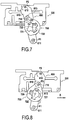
- the figure 7 shows the connecting rods 600 and 700 as well as the external carriage 220 in a position corresponding to the open position of the cutting apparatus as shown in FIGS. Figures 1A and 1B .
- the outer carriage 220 has moved in the direction A, which caused the pivoting of the first link 600 around the first point of rotation P1 which, itself, caused the pivoting of the second link 700 around the center 722 of the light 720 by sliding of the pin 710 in the oblong groove 613, the center 722 corresponding to the axis of rotation of the second rod 700.
- the pivoting of the rod 700 causes the rotation of the shaft 101 (not shown in FIG. the figure 8 ) at an angle sufficient to allow the closing of the breaking poles as shown on the Figures 2A and 2B .
- the Figures 9, 10 and 11 show the relative movements of the inner carriages 210 and outer 220 to move from the open position (cut position) to the closed position of the breaking poles by triggering the movement of the external carriage.
- the figure 11 shows the inner carriages 210 and outer 220 in their cut position corresponding to the position of the first connecting rod 600 and the second connecting rod 700 shown in FIG. figure 7 , namely the opening position of the breaking poles.
- the figure 11 shows the inner carriages 210 and outer 220 in their closed position corresponding to the position of the first rod 600 and the second rod 700 shown on the figure 8 that is, the closing position of the breaking poles.
- the first latching pawl 270 temporarily blocks the movement of the external carriage 220 in the direction A indicated on the figure 10 so as to allow, as a first step, the compression of the accumulation spring 230 ( figure 10 ) and, in a second step, triggering the movement of the external carriage 220 in the direction A under the effect of the action of the spring 230 ( figure 11 ). More specifically, as illustrated on the figure 9 when the first pawl 270 is in the low position, it bears against flanges 223 formed in the upper part of the external carriage 220, which makes it possible to retain the external carriage.
- the inner carriage 210 comprises in its upper part two ramps 214 which are intended to lift the first latch pawl 270 during the displacement of the inner carriage 210 in the direction A as indicated on FIG. figure 10 and gradually disengaging the pawl 270 from the flanges 223 to release the movement of the outer carriage as shown in FIG. figure 12 .
- Figures 11, 12 and 9 show the relative movements of the inner and outer trolleys to move from the closed position to the open position of the breaking poles by triggering the movement of the external carriage, the figure 9 showing the relative position between the carriages 210 and 220 corresponding to the position of the rods 600 and 700 shown in FIG. figure 7 (opening position of the breaking poles), the figure 11 showing the relative position between the carriages 210 and 220 corresponding to the position of the rods 600 and 700 shown in FIG. figure 8 (closing position of the breaking poles).
- the second rocker pawl 280 is intended to momentarily block the movement of the external slide 220 in the direction B indicated on the figure 12 so as to allow, as a first step, the compression of the accumulation spring 230 ( figure 12 ) and, in a second step, triggering the movement of the external carriage 220 in the direction B under the effect of the action of the spring 230 ( figure 9 ). More specifically, as illustrated on the figure 11 when the second pawl 280 is in position low, it is supported against flanges 224 formed in the upper part of the outer carriage 220, which allows to retain the external carriage.
- the inner carriage 210 comprises in its upper part two ramps 215 which are intended to lift the first rocker pawl 280 during the displacement of the inner carriage 210 in the direction B as indicated on FIG. figure 12 and gradually disengaging the pawl 280 from the flanges 224 until the movement of the outer carriage is released, which then moves into the cut position as shown in FIG. figure 9 .
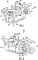
- the accumulation control system 100 is in the closed position as shown in FIG. figure 13A and corresponding to the position of the breaking poles 10 as shown on the Figures 2A and 2B .
- the control handle 102 which is in its closed position is then actuated towards its cut-off position as indicated by the arrow C on the Figure 13B .
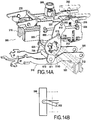
- the figure 14A represents the position of the trigger control system 100 when the control handle 102 has been tilted to its cutoff position, as shown in FIG. Figure 14B , while one or more cutoff poles 10 have remained locked in their closed position.
- the inner carriage 210 has slid to a position that normally triggers the movement of the external carriage in its cut position under the effect of the spring 230 (not visible on the figure 14A ) and by the release of the external carriage 220 by the latch 280 as previously explained.
- at least one of the breaking poles connected to the system 100 is locked in its closed position, which has the effect of blocking the rotation of the cut-off shaft 101 and preventing any tilting of the 700 and 600 rods.
- the first link 600 being locked in its closed position, the external carriage 220 can not slide in its open position and remains locked in its closed position as shown in FIG. figure 14A .
- the inner carriage 210 comprises abutments 216 which are intended to bear on contact portions 226 provided on the external carriage when the latter is locked in its closed position as illustrated in FIG. figure 14A .
- the stops 216 will allow to force on the external carriage with the internal carriage.
- Forcing the opening of the breaking poles or poles according to the invention starts from the position of the control system as shown in FIG. figure 14A .
- the control handle 102 is then actuated beyond its cutoff position so as to move the inner carriage 210 beyond its cutoff position.
- the inner carriage 210 being in abutment against the external carriage 220, it forces on the outer carriage so as to move it to its cutoff position.
- Forcing the internal carriage on the external carriage 220 drives, via the pins 612 and 622 in engagement with the external carriage, the pivoting of the first link 600 about a third point of rotation P3 corresponding to the pin 710 of the second link 700 which is engaged in the oblong groove 613 formed in the arm 610 of the first rod 600.
- the connecting rod 600 will swing around the point of rotation P3 until it comes to a stop.
- the link 600 being in abutment against the inclined portions 3140 and 3150, the force F exerted by the external carriage 220 on the axes 612 and 622 will directly oppose the blocking force transmitted to the connecting rod 700 via the shaft. cut 101 to continue the tilting of the connecting rod 600 around the point of rotation P3.
- a force greater than the locking force of the welded breaking poles or poles is applied to the control handle 102, the contacts of the pole or poles are unsoldered, thereby releasing any stress on the link rod 700.
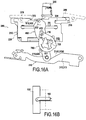
- the movement the external carriage is then no longer locked so that it moves into the cut position under the effect of the spring 230 (not visible on the figure 15A ), which position is represented on the figure 16A .
- the control handle 102 once released returns to its normal position of cut as illustrated on the figure 16B .
- the axis 611 of the first link 600 abuts on inclined portions 3140 and 3150 present on the hook 310 of the trigger mechanism 300.
- the accumulation control system of the invention may not understand such a trigger mechanism.
- the system of the invention simply comprises a stop fixed at a location corresponding to that where the axis 611 connecting the arms 610 and 620 of the first link 600 abuts on inclined portions 3140 and 3150 present respectively on the first and second arms 312 and 313 of the hook 310.
- the accumulation control system of the invention further comprises a lockout device for locking the control system in the pole breaking position.
- the padlocking device makes it possible to control the cut-off of all the energy sources controlled by the at least one cut-off pole connected to the control system. It is thus possible to securely isolate all dangerous energy sources during an intervention on an equipment, a system or a machine and this, until the end of the intervention.
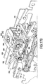
- a padlocking device 800 according to an embodiment of the invention and used with the accumulation control device 100 described above is shown on the Figures 17A and 17B .
- the device 800 comprises a casing 810 formed in two parts 811 and 812 which are fixed together by a screw 813, the casing then being fastened to the cheeks 110 and 120 of the accumulation control system 100 by screws 814.
- the casing 810 contains a lockout member 820 and a locking member 830 for cooperating together as described hereinafter.
- the lockout member 820 includes a lockout tab 821 connected to an axle 822 held in the housing 810 and through which the lockout tab is pivotable between a retracted position in the housing 810 as shown in FIG.
- the tongue 821 being out of the housing, it is possible to place one or more locks in a light 8210 formed in the tongue 821 to lock the system 100 in the cut position.
- the lockout device 800 uses a locking element. lock 830 which prevents the exit of the padlock tongue 821, even if the control handle is moved to its cut position.
- the locking element 830 comprises a blocking portion 831 intended to cooperate with the lockout element 820 and the angle gearbox 260.
- a rod 832 intended to test the position of the rocker pawl 280 extends from the portion blocking 831.
- the axis 822 of the lockout element 820 is provided with a pin 8220 which is in contact with a bearing portion 8310 of the locking portion 831 of the locking element 830.
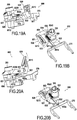
- the pivoting of the locking tab 821 between its retracted position ( Figures 19A and 19B ) and its output position of the housing ( Figures 20A and 20B ) causes the locking element to move between its neutral position and its locking position corresponding to a translation of the locking element 830 towards the latch pawl 270.
- the locking element 830 also makes it possible to block the rotation of the control handle 102 once the lockout tab has been output from the housing.
- the locking portion 831 of the locking element comprises a recess 834 comprising a stop 8340 intended to cooperate with a key 263 present on the angle gearbox 260 ( figure 19B ) when the locking element is in its locking position as illustrated on the figure 20B . In this position, the movement of the bevel gear is locked in rotation in the direction of closing the cutoff pole or poles 10 thus preventing any movement of the control handle in this direction.
- control system of the invention also makes it possible to exceed the force defined by the standard (i.e. three times the normal maneuvering force), thus providing more security in an electrical installation.
Landscapes
- Driving Mechanisms And Operating Circuits Of Arc-Extinguishing High-Tension Switches (AREA)
- Breakers (AREA)
Description
La présente invention se rapporte au domaine général des appareils de coupure électrique et plus particulièrement aux systèmes permettant d'actionner la coupure dans ce type d'appareils.The present invention relates to the general field of electrical switchgear and more particularly to systems for operating the break in such devices.
Ce type d'installation comprend un ou plusieurs pôles de coupure électrique tels que des interrupteurs-sectionneurs déclenchables, des inter-fusibles déclenchables, des commutateurs déclenchables et des disjoncteurs. Les fonctions principales de ces pôles sont :
- établissement et interruption du courant électrique en charge, en surcharge et sur des courts circuits,
- protection du site et des personnes contre les risques électriques,
- garantie de la sécurité de l'utilisateur (actionnement, consignation et isolement).
- Establishment and interruption of electric current under load, overload and on short circuits,
- protection of the site and people against electrical risks,
- guarantee of the safety of the user (actuation, recording and isolation).
Les appareils de coupure électrique sont équipés d'un système de commande relié aux pôles de coupure électrique à partir duquel la coupure du courant électrique est commandée. Le système de commande représente l'élément de sécurité le plus important de l'installation car c'est lui qui assure le niveau de performance et de fiabilité des appareils de coupure électrique ainsi que l'interface entre un utilisateur et la partie électrique de puissance du ou des dispositifs alimentés en courant électriques.The electric switchgear is equipped with a control system connected to the electric breaking poles from which the power cut is controlled. The control system represents the most important safety element of the installation because it ensures the level of performance and reliability of the electrical switchgear as well as the interface between a user and the electrical part of power the device or devices powered by electric current.
Le système de commande permet à l'utilisateur de basculer le ou les pôles de coupure d'une position fermée (établissement du courant électrique), dite « position de fermeture », à une position ouverte (coupure du courant électrique), dite « position de coupure », et inversement, au moyen d'une poignée de commande. Plus précisément, le système de commande comprend un mécanisme à accumulation formé principalement d'un chariot interne relié à la poignée de commande et d'un chariot externe relié à un axe de commande des pôles de coupure, le chariot interne coulissant dans le chariot externe. Un ressort est interposé entre les deux chariots de manière à accumuler de l'énergie mécanique lors du déplacement du chariot interne par la poignée de commande et à restituer cette énergie au chariot externe en fin de course de la poignée de commande afin de permettre une ouverture ou une fermeture rapide et fiable du ou des pôles de coupure.The control system allows the user to switch the cutoff poles or poles from a closed position (establishment of the electric current), called the "closed position", to an open position (cut-off of the electric current), called "position "cut-off", and vice versa, by means of a control handle. More specifically, the control system comprises a storage mechanism formed mainly of an internal carriage connected to the control handle and an external carriage connected to a control axis of the breaking poles, the internal carriage sliding in the external carriage . A spring is interposed between the two carriages so as to accumulate mechanical energy during movement of the internal carriage by the control handle and to restore this energy to the external carriage at the end of travel of the control handle in order to allow a quick and reliable opening or closing of the cutoff pole or poles.
Cependant, en cas de soudure d'un ou des pôles de coupure dans la position de fermeture, le chariot externe du système de commande, qui est relié aux pôles par un arbre de commande, peut rester bloqué alors que la poignée de commande a réalisé l'ensemble de sa course entre la position de fermeture et la position de coupure. Dans ce cas, le système de commande n'est plus utilisable en ce que la soudure d'un ou plusieurs pôles empêche la commande de l'ouverture de l'ensemble des pôles.However, in case of welding of one or more breaking poles in the closed position, the external carriage of the control system, which is connected to the poles by a control shaft, can remain blocked while the control handle has realized. the entire stroke between the closed position and the cut position. In this case, the control system is no longer usable in that the welding of one or more poles prevents the control of the opening of all the poles.
La soudure d'un ou des pôles de coupure quand elle ne peut être vaincue par la force du ressort du mécanisme à déclenchement entraîne des problèmes de sécurité très importants. En effet, si la poignée de commande a été déplacée jusqu'à sa position correspondant à la position normale d'ouverture du ou des pôles de coupure, l'opérateur peut penser que l'ouverture du ou des pôles a bien été réalisée alors que ce n'est pas le cas.The welding of one or more breaking poles when it can not be overcome by the spring force of the triggering mechanism causes very important safety problems. Indeed, if the control handle has been moved to its position corresponding to the normal opening position of the cutoff poles or poles, the operator may think that the opening of the pole or poles has been achieved while This is not the case.
En outre, les normes de sécurité imposent la possibilité de pouvoir verrouiller la position de coupure de la poignée. Toutefois, en cas de soudure d'un ou plusieurs pôles de coupure, cette exigence de sécurité est inefficace si la poignée de commande peut être verrouillée dans sa position de coupure alors que le ou les pôles de coupure sont toujours dans leur position fermée.
La présente invention a pour but de proposer une nouvelle conception de système de commande qui permet de forcer des pôles de coupure dont les contacts sont soudés.The object of the present invention is to propose a new design of a control system which makes it possible to force cut-off poles whose contacts are soldered.
Ce but est atteint grâce à un système de commande à accumulation pour un ou plusieurs pôles de coupure électrique selon la revendication 1. Le système comprend en particulier :
- un mécanisme à accumulation comprenant une poignée de commande mobile au moins entre une position de fermeture et une position de coupure, et inversement, un chariot interne relié à la poignée de commande et un chariot externe, le chariot interne coulissant dans le chariot externe lors du déplacement de la poignée de commande entre la position de fermeture et la position de coupure, et inversement, un ressort étant interposé entre le chariot interne et le chariot externe,
- une première bielle reliée au chariot externe et pivotante autour d'un premier point de rotation entre une première position et une deuxième position, et inversement, par actionnement de la poignée de commande du mécanisme à accumulation entre la position de coupure et la position de fermeture, et inversement,
- une deuxième bielle pivotante autour d'un axe de rotation destiné à être relié à un ou plusieurs pôles de coupure, la deuxième bielle étant reliée à la première bielle par une liaison coulissante de sorte que le déplacement de la première bielle entre la première position et la deuxième position, respectivement entre la deuxième position et la première position, entraîne le pivotement de la deuxième bielle autour de l'axe de rotation entre une position d'ouverture du ou des pôles de coupure et une position de fermeture du ou des pôles de coupure, respectivement entre une position de fermeture du ou des pôles de coupure et une position d'ouverture du ou des pôles de coupure, le système de commande comprend des moyens pour exercer une force de pivotement supplémentaire sur la deuxième bielle lorsque la poignée de commande est actionnée au-delà de la position de coupure.
- an accumulation mechanism comprising a movable control handle at least between a closed position and a cut-off position, and vice versa, an internal carriage connected to the control handle and an external carriage, the inner carriage sliding in the external carriage during the moving the control handle between the closed position and the cut-off position, and vice versa, a spring being interposed between the internal carriage and the external carriage,
- a first connecting rod connected to the external carriage and pivoting around a first point of rotation between a first position and a second position, and vice versa, by actuating the control handle of the accumulation mechanism between the cut-off position and the closed position and vice versa
- a second connecting rod pivoting about an axis of rotation intended to be connected to one or more breaking poles, the second connecting rod being connected to the first connecting rod by a sliding connection so that the displacement of the first link between the first position and the second position, respectively between the second position and the first position, causes the pivoting of the second connecting rod about the axis of rotation between an open position of the cut-off pole (s) and a closing position of the at least one pole of cutoff, respectively between a closing position of the cutoff poles and an opening position of the breaking poles or poles, the control system comprises means for exerting an additional pivoting force on the second link when the control handle is operated beyond the cutoff position.
En permettant une sur-course de la poignée de commande au-delà de la position de coupure, le système de commande à déclenchement de la présente invention permet de détecter un éventuel blocage (i.e. soudure) d'un ou plusieurs pôles de coupure reliés au système de commande. En effet, si un ou plusieurs pôles de coupure sont soudés, il est possible de le détecter par une résistance dans la poignée de commande lors de son actionnement au-delà de la position de coupure. En outre, lorsqu'une force supérieure à l'effort de blocage du ou des pôles de coupure soudés est appliquée à la poignée de commande, les contacts du ou des pôles peuvent être débloqués, ce qui permet au système de commande de revenir dans sa position normale de coupure.By allowing an over-travel of the control handle beyond the cut-off position, the triggering control system of the present invention makes it possible to detect a possible blockage (ie welding) of one or more cut-off poles connected to the control system. Indeed, if one or more breaking poles are welded, it is possible to detect it by a resistor in the control handle when it is actuated beyond the cutoff position. In addition, when a force greater than the locking force of the welded breaking poles or poles is applied to the control handle, the contacts of the pole or poles can be released, which allows the control system to return to its position. Normal position of cut.
Selon l'invention, le chariot interne comprend au moins une butée apte à venir en contact avec le chariot externe lorsque le chariot interne est déplacé par la poignée de commande vers la position d'ouverture du ou des pôles de coupure tandis que le chariot externe est bloqué dans la position de fermeture des pôles de coupure de manière à forcer le déplacement du chariot externe vers la position de coupure au moyen de la poignée de commande. En permettant la mise en butée du chariot interne sur le chariot externe, il est possible de forcer l'ouverture du ou des pôles de coupure bloqués à partir de la poignée de commande.According to the invention, the internal carriage comprises at least one stop adapted to come into contact with the external carriage when the inner carriage is moved by the control handle towards the opening position of the cutoff pole or poles while the external carriage is locked in the closed position of the breaking poles so as to force the movement of the external carriage towards the switch position by means of the control handle. By allowing the internal carriage to abut on the external carriage, it is possible to force the opening of the cutoff pole or poles blocked from the control handle.
Selon une autre caractéristique du système de commande de l'invention, celui-ci comprend un dispositif de cadenassage comprenant un élément de cadenassage mobile entre une position neutre et une position de cadenassage permettant le verrouillage du système de commande à accumulation dans la position de coupure et en ce que ledit dispositif de cadenassage comprend en outre des moyens de contrôle pour bloquer l'élément de cadenassage dans la position neutre lorsque le chariot externe est bloqué dans la position de fermeture des pôles de coupure alors que la poignée de commande est déplacée dans la position de coupure.According to another characteristic of the control system of the invention, it comprises a lockout device comprising a lockout element movable between a neutral position and a lockout position for locking the accumulation control system in the cutoff position and in that said padlocking device further comprises control means for locking the lockout element in the neutral position when the external carriage is locked in the closed position of the breaking poles while the control handle is moved in the breaking position.
Ainsi, le système de l'invention peut être verrouillé dans sa position de coupure, et ce de manière totalement sécurisée car celui-ci ne peut pas être verrouillé si le chariot externe est bloqué dans la position de fermeture des pôles de coupure même si la poignée de commande est déplacée dans la position de coupure. En d'autres termes, le système de commande ne peut pas être verrouillé si un ou plusieurs pôles de coupure sont soudés dans leur position de fermeture.Thus, the system of the invention can be locked in its breaking position, and in a completely secure manner because it can not be locked if the external carriage is locked in the closed position of the breaking poles even if the control handle is moved to the cut position. In other words, the control system can not be locked if one or more cutoff poles are soldered in their closed position.
Selon un aspect du système de commande de l'invention, celui-ci comprend au moins un cliquet à bascule mobile entre une position haute lorsque le chariot externe est dans la position de fermeture des pôles de coupure et une position basse lorsque ledit chariot externe est dans la position d'ouverture des pôles de coupure et en ce que le dispositif de cadenassage comprend un élément de verrouillage mobile entre une position neutre lorsque le cliquet à bascule est dans la position basse et une position de blocage lorsque le cliquet à bascule est dans la position haute de manière à bloquer l'élément de cadenassage dans la position neutre lorsque le chariot externe est bloqué dans la position de fermeture des pôles de coupure alors que la poignée de commande est déplacée dans la position de coupure.According to one aspect of the control system of the invention, it comprises at least one rocker pawl movable between a high position when the external carriage is in the closed position of the breaking poles and a low position when said external carriage is in the open position of the breaking poles and in that the padlocking device comprises a locking element movable between a neutral position when the rocker pawl is in the low position and a blocking position when the rocker pawl is in the high position so as to lock the lockout element in the neutral position when the external carriage is locked in the closed position of the cutoff poles while the control handle is moved to the cutoff position.
L'élément de verrouillage est ainsi apte à tester la position du cliquet à bascule et à n'autoriser le verrouillage du système dans la position de coupure que si le cliquet est dans la position basse, position indiquant que le chariot externe est dans la position de coupure et que, par conséquent, aucun pôle de coupure n'est resté bloqué dans la position de fermeture.The locking element is thus able to test the position of the rocker pawl and to authorize the locking of the system in the cutoff position only if the pawl is in the low position, position indicating that the external carriage is in the position and therefore no break-off pole has been blocked in the closed position.
Selon une caractéristique supplémentaire du système de commande de l'invention, l'élément de verrouillage est apte à bloquer le déplacement de la poignée de commande lorsque ledit élément de verrouillage est dans la position de blocage. Ainsi, on empêche en outre tout déplacement de la poignée de commande.According to an additional characteristic of the control system of the invention, the locking element is able to block the displacement of the control handle when said locking element is in the locking position. Thus, it further prevents any movement of the control handle.
Selon une autre caractéristique supplémentaire du système de commande de l'invention, l'élément de cadenassage comprend une languette comportant une lumière accessible lorsque ledit élément de cadenassage est dans la position de cadenassage. Il est ainsi possible de cadenasser le système dans la position de coupure en plaçant un ou plusieurs cadenas dans la lumière, ce qui permet de sécuriser l'intervention d'un ou plusieurs opérateurs.According to another additional feature of the control system of the invention, the lockout element comprises a tab having an accessible light when said lockout element is in the lockout position. It is thus possible to lock the system in the cutoff position by placing one or more padlocks in the light, which makes it possible to secure the intervention of one or more operators.
La présente invention a également pour objet un appareil de coupure électrique comprenant un ou plusieurs pôles de coupure électrique équipés d'un barreau mobile, caractérisé en ce que ledit appareil comprend en outre un système de commande à accumulation selon l'invention, un arbre de coupure reliant chaque barreau mobile du ou des pôles de coupure à l'axe de rotation de la deuxième bielle.The present invention also relates to an electric switchgear device comprising one or more electric breaking poles equipped with a movable bar, characterized in that said apparatus further comprises a storage control system according to the invention, a control shaft. cut connecting each movable bar of the cutoff poles or poles to the axis of rotation of the second link.
D'autres caractéristiques et avantages de l'invention ressortiront de la description suivante de modes particuliers de réalisation de l'invention, donnés à titre d'exemples non limitatifs, en référence aux dessins annexés, sur lesquels:
- la
figure 1A est une vue schématique montrant un système de commande à déclenchement dans une position de coupure conformément à un mode de réalisation de l'invention, - la
figure 1B montre un barreau mobile dans la position de coupure du système de lafigure 1A , - la
figure 2A est une vue schématique montrant un système de commande à déclenchement dans une position de fermeture conformément à un mode de réalisation de l'invention, - la
figure 2B montre un barreau mobile dans la position de fermeture du système de lafigure 2A , - la
figure 3 est une vue schématique en perspective éclatée du système de commande à déclenchement desfigures 1A et 2A , - la
figure 4 est une vue schématique en perspective éclatée du mécanisme à accumulation représenté sur lafigure 3 , - les
figures 5 et 6 sont des vues en perspective du mécanisme à accumulation une fois monté, - la
figure 7 est une vue schématique simplifiée montrant la position des première et deuxième bielles lorsque le système de commande est dans une position de coupure, - la
figure 8 est une vue schématique simplifiée montrant la position des première et deuxième bielles lorsque le système de commande est actionné vers une position de fermeture, - la
figure 9 est une vue en coupe du mécanisme à accumulation lorsque le système de commande à déclenchement est dans une position de coupure, - la
figure 10 est une vue en coupe du mécanisme à accumulation lorsque la poignée de commande du système de commande à déclenchement est actionné vers une position de fermeture, avec le ressort du mécanisme à accumulation comprimé, - la
figure 11 est une vue en coupe du mécanisme à accumulation lorsque le système de commande à déclenchement est dans une position de fermeture, - la
figure 12 est une vue en coupe du mécanisme à accumulation lorsque la poignée de commande du système de commande à déclenchement est actionné vers une position d'ouverture, avec le ressort du mécanisme à accumulation comprimé, - la
figure 13A est une vue schématique en perspective montrant une partie des éléments constitutifs du système de commande à accumulation desfigures 1A et 2A lorsque celui-ci est dans une position de fermeture, - la
figure 13B est une vue en schématique montrant la position de la poignée de commande du système de commande à accumulation de lafigure 13A , - la
figure 14A est une vue schématique en perspective du système de lafigure 13A lorsque le chariot externe est bloqué dans la position de fermeture des pôles de coupure alors que la poignée de commande est tournée vers la position de coupure, - la
figure 14B est une vue en schématique montrant la position de la poignée de commande du système de commande à accumulation de lafigure 14A , - la
figure 15A est une vue schématique en perspective montrant le système de lafigure 14A au début du forçage du chariot interne sur le chariot externe, - la
figure 15B est une vue en schématique montrant la position de la poignée de commande du système de commande à accumulation de lafigure 15A , - la
figure 16A est une vue schématique en perspective montrant le système de lafigure 15A après forçage et déblocage des pôles de coupure - la
figure 16B est une vue en schématique montrant la position de la poignée de commande du système de commande à accumulation de lafigure 16A , - la
figure 17A est une vue schématique en perspective éclatée partiellement montrant le système de commande à accumulation de l'invention muni d'un dispositif de cadenassage, - la
figure 17B est une vue schématique en perspective du système de lafigure 17A une fois le dispositif de cadenassage monté, le système de commande étant dans la position de fermeture, - la
figure 18 est une vue schématique en perspective du système de commande à accumulation desfigures 17A et17B dans la position de coupure, - les
figures 19A et 19B sont des vues schématiques en perspective montrant les éléments constitutifs du dispositif de cadenassage lorsque le chariot externe est bloqué dans la position de fermeture des pôles de coupure, - les
figures 20A et 20B sont des vues schématiques en perspective montrant les éléments constitutifs du dispositif de cadenassage lorsque le chariot externe dans la position de coupure des pôles de coupure.
- the
Figure 1A is a schematic view showing a trigger control system in an off position according to an embodiment of the invention, - the
Figure 1B shows a moving bar in the cutoff position of the system of theFigure 1A , - the
Figure 2A is a schematic view showing a triggering control system in a closed position according to an embodiment of the invention, - the
Figure 2B shows a moving bar in the closed position of the system of theFigure 2A , - the
figure 3 is a schematic perspective exploded view of the control system triggeringFigures 1A and 2A , - the
figure 4 is a diagrammatic perspective exploded view of the accumulation mechanism shown in FIG.figure 3 , - the
Figures 5 and 6 are perspective views of the accumulation mechanism once mounted, - the
figure 7 is a simplified schematic view showing the position of the first and second links when the control system is in an off position, - the
figure 8 is a simplified schematic view showing the position of the first and second links when the control system is actuated to a closed position, - the
figure 9 is a sectional view of the accumulation mechanism when the tripping control system is in an off position, - the
figure 10 is a sectional view of the accumulation mechanism when the control handle of the triggering control system is actuated to a closed position, with the spring of the compressed accumulation mechanism, - the
figure 11 is a sectional view of the accumulation mechanism when the triggering control system is in a closed position, - the
figure 12 is a sectional view of the accumulation mechanism when the control handle of the triggering control system is actuated to an open position, with the spring of the compressed accumulation mechanism, - the
figure 13A is a schematic perspective view showing a part of the constituent elements of the accumulation control system of theFigures 1A and 2A when it is in a closed position, - the
Figure 13B is a schematic view showing the position of the control handle of the accumulation control system of thefigure 13A , - the
figure 14A is a schematic perspective view of the system from thefigure 13A when the external carriage is locked in the closed position of the cut-off poles while the control handle is turned to the cut-off position, - the
Figure 14B is a schematic view showing the position of the control handle of the accumulation control system of thefigure 14A , - the
figure 15A is a schematic perspective view showing the system of thefigure 14A at the beginning of the forcing of the internal trolley on the external trolley, - the
figure 15B is a schematic view showing the position of the control handle of the accumulation control system of thefigure 15A , - the
figure 16A is a schematic perspective view showing the system of thefigure 15A after forcing and unblocking of the breaking poles - the
figure 16B is a schematic view showing the position of the control handle of the accumulation control system of thefigure 16A , - the
Figure 17A is a schematic perspective exploded view partially showing the accumulation control system of the invention provided with a lockout device, - the
Figure 17B is a schematic perspective view of the system from theFigure 17A once the lockout device is mounted, the control system being in the closed position, - the
figure 18 is a schematic perspective view of the accumulation control system ofFigures 17A and17B in the cutoff position, - the
Figures 19A and 19B are schematic perspective views showing the constituent elements of the lockout device when the external carriage is locked in the closed position of the breaking poles, - the
Figures 20A and 20B are schematic perspective views showing the constituent elements of the lockout device when the external carriage in the cutoff position of the poles.
La
La
- un mécanisme à
accumulation 200, - un mécanisme à déclenchement 300,
- un module de commande de déclenchement 400,
- un module de contacts auxiliaires 500,
- une première bielle pivotante 600,
- une deuxième bielle pivotante 700.
- a
storage mechanism 200, - a
trigger mechanism 300, - a
trigger control module 400, - an
auxiliary contact module 500, - a
first pivoting rod 600, - a
second pivoting rod 700.
Ces éléments sont assemblés les uns avec les autres et maintenus au moyens de deux joues en tôle 110 et 120.These elements are assembled with each other and maintained by means of two
Comme illustré sur la
un chariot interne 210,un chariot externe 220,un ressort d'accumulation 230,- un guide de ressort 240,
- des guides de chariots 250,
un renvoi d'angle 260,- un premier cliquet à bascule 270,
- un deuxième cliquet à bascule 280.
- an
internal carriage 210, - an
external carriage 220, - an
accumulation spring 230, - a
spring guide 240, - trolley guides 250,
- an
angle gear 260, - a
first ratchet 270, - a
second rocker pawl 280.
Les chariots internes 210 et externe 220 sont montés de manière coulissante l'un par rapport à l'autre, les guides de chariots 250 dirigeant les glissements relatifs entre les deux chariots. Lors du montage du chariot interne 210 dans le chariot externe 220, le ressort d'accumulation 230 est interposé entre les deux chariots. Plus précisément, le ressort 230 est maintenu sur le guide ressort 240 qui est lui-même fixé sur deux pattes de fixation 221 et 222 respectivement présentes aux deux extrémités du chariot externe 220. Au repos, le ressort 230 s'étend entre les deux pattes 221 et 222 comme illustré sur la
Comme représenté sur la
La
On explique maintenant comment est commandé le déclenchement du mouvement du chariot externe entre la position d'ouverture et la position de fermeture des pôles de coupure et inversement.It is now explained how is triggered the movement of the external carriage between the open position and the closed position of the breaking poles and vice versa.
Les
Le premier cliquet à bascule 270 permet de bloquer momentanément le déplacement du chariot externe 220 dans le sens A indiqué sur la
De la même manière, les
Le deuxième cliquet à bascule 280 est destiné à bloquer momentanément le déplacement du chariot externe 220 dans le sens B indiqué sur la
On décrit maintenant l'opération consistant à forcer l'ouverture d'un ou plusieurs pôles de coupure lorsqu'un ou plusieurs d'entre eux sont bloqués dans la position de fermeture, c'est-à-dire lorsqu'au moins un contact mobile 11 d'un pôle de coupure 10 relié au système de commande à accumulation 100 reste soudé au contact fixe 13 du pôle.The operation of forcing the opening of one or more cut-off poles when one or more of them are locked in the closed position, that is to say when at least one contact, is now described. mobile 11 of a
Au départ, le système de commande à accumulation 100 est dans la position de fermeture telle que représentée sur la
La
Comme illustré sur la
Le forçage de l'ouverture du ou des pôles de coupure conforme à l'invention commence à partir de la position du système de commande telle qu'illustrée sur la
Dans le mode de réalisation décrit ici, l'axe 611 de la première bielle 600 vient en butée sur des portions inclinées 3140 et 3150 présentes sur le crochet 310 du mécanisme à déclenchement 300. Toutefois, le système de commande à accumulation de l'invention peut ne pas comprendre un tel mécanisme à déclenchement. Dans ce cas, le système de l'invention comprend simplement une butée fixée à un emplacement correspondant à celui où l'axe 611 reliant les bras 610 et 620 de la première bielle 600 vient en butée sur des portions inclinées 3140 et 3150 présentes respectivement sur les premier et deuxième bras 312 et 313 du crochet 310.In the embodiment described here, the
Conformément à un mode de réalisation du système de commande à accumulation de l'invention, celui-ci comprend en outre un dispositif de cadenassage permettant de verrouiller le système de commande dans la position de coupure des pôles. Le dispositif de cadenassage permet de contrôler la coupure des toutes les sources d'énergie commandées par le ou les pôles de coupure reliés au système de commande. Il est ainsi possible d'isoler de manière sécurisée toutes les sources d'énergie dangereuses lors d'une intervention sur un équipement, un système ou une machine et ce, jusqu'à la fin de l'intervention.According to an embodiment of the accumulation control system of the invention, it further comprises a lockout device for locking the control system in the pole breaking position. The padlocking device makes it possible to control the cut-off of all the energy sources controlled by the at least one cut-off pole connected to the control system. It is thus possible to securely isolate all dangerous energy sources during an intervention on an equipment, a system or a machine and this, until the end of the intervention.
Un dispositif de cadenassage 800 conforme à un mode de réalisation de l'invention et utilisé avec le dispositif de commande à accumulation 100 décrit précédemment est représenté sur les
Toutefois, afin d'éviter tout cadenassage du système 100 alors qu'un ou plusieurs pôles de coupure reliés à celui-ci sont soudés dans la position de fermeture, le dispositif de cadenassage 800 utilise un élément de verrouillage 830 qui permet d'empêcher la sortie de la languette de cadenassage 821, et ce même si la poignée de commande est déplacée dans sa position de coupure. En effet, comme représenté sur les
Plus précisément, l'axe 822 de l'élément de cadenassage 820 est muni d'un ergot 8220 qui est en contact avec une partie d'appui 8310 de la portion de blocage 831 de l'élément de verrouillage 830. Le pivotement de la languette de cadenassage 821 entre sa position rétractée (
Lorsque le cliquet à bascule 270 est dans sa position haute alors que la poignée de commande a été tournée jusque dans sa position de coupure comme représentés sur les
Lorsqu'une force supérieure à l'effort de blocage du ou des pôles de coupure soudés est appliquée à la poignée de commande comme expliqué ci-avant, les contacts du ou des pôles sont débloqués et le système 100 revient dans sa position normale de coupure comme illustrée sur la
L'élément de verrouillage 830 permet en outre de bloquer la rotation de la poignée de commande 102 une fois la languette de cadenassage sortie du boîtier. En effet, la portion de blocage 831 de l'élément de verrouillage comporte un évidement 834 comprenant une butée 8340 destinée à coopérer avec une clavette 263 présente sur le renvoi d'angle 260 (
Si l'effort exercé par l'opérateur sur la poignée de commande (limité à trois fois l'effort normal de manoeuvre) ne permet d'ouvrir les contacts soudés, le cadenassage du système de commande reste impossible. En outre, après le relâchement de l'effort sur la poignée, celle-ci se place dans une position indiquant clairement à l'opérateur que l'appareil est toujours dans une position de fermeture (normatif).If the effort exerted by the operator on the control handle (limited to three times the normal maneuvering force) does not open the welded contacts, lockout of the control system remains impossible. In addition, after the release of the force on the handle, it is placed in a position clearly indicating to the operator that the device is still in a closed position (normative).
Le système de commande de l'invention permet également de dépasser l'effort défini par la norme (i.e. trois fois l'effort normal de manoeuvre), apportant, par conséquent, plus de sécurité dans une installation électrique.The control system of the invention also makes it possible to exceed the force defined by the standard (i.e. three times the normal maneuvering force), thus providing more security in an electrical installation.
Claims (6)
- An accumulator control system (100) for one or more electrical breaker poles (10), the system comprising:• an accumulator mechanism (200) comprising a control handle (102) that is movable at least between a closing position and a breaking position, and vice versa, an inner carriage (210) connected to the control handle (102) and an outer carriage (220), the inner carriage (210) sliding in the outer carriage (220) during movement of the control handle (102) between the closing position and the breaking position, and vice versa, a spring (230) being interposed between the inner carriage (210) and the outer carriage (220);• a first link (600) connected to the outer carriage (220) and pivoting about a first pivot point (P1) between a first position and a second position, and vice versa, by actuating the control handle (102) of the accumulator mechanism (200) between the breaking position and the closing position, and vice versa;• a second link (700) pivotable about a pivot axis (722) for connecting to one or more breaker poles (10), the second link (700) being connected to the first link (600) by a sliding connection (710, 613) so that the movement of the first link (600) between the first position and the second position, or conversely between the second position and the first position, causes the second link (700) to pivot about the pivot axis (722) between a position for opening the breaker pole(s) (10) and a position for closing the breaker pole(s) (10), or conversely between a position for closing the breaker pole(s) (10) and a position for opening the breaker pole(s) (10) ;the control system includes means for exerting additional pivoting force on the second link (700) when the control handle is actuated beyond the breaking position, characterized in that the inner carriage (210) includes at least one abutment (216) suitable for coming into contact with the outer carriage (220) when the inner carriage (210) is moved by the control handle (102) towards the breaking position of the breaker pole(s) (10) while the outer carriage (220) is blocked in the position for closing the breaker poles (10) so as to force the outer carriage (220) to move towards the position for opening by means of the control handle (102).
- A system according to claim 1, characterized in that it includes a locking device (800) comprising a locking element (820) that is movable between a neutral position and a locking position making it possible to lock the accumulation control system (100) in the breaking position, and in that said locking device (800) further comprises control means for blocking the locking element (820) in the neutral position when the outer carriage (220) is blocked in the position for closing the breaker poles (10) while the control handle (102) is being moved into the breaking position.
- A system according to claim 2, characterized in that it comprises at least one rocker pawl (270) that is movable between a high position when the outer carriage (220) is in the position for closing the breaker poles (10) and a low position when said outer carriage (280) is in the position for opening the breaker poles (10) and in that the locking device (800) comprises a latch element (830) that is movable between a neutral position when the rocker pawl (280) is in the low position and a blocking position when the rocker pawl (280) is in the high position in such a manner as to block the locking element (820) in the neutral position when the outer carriage (220) is blocked in the position for closing the breaker poles (10) while the control handle (102) is being moved into the breaking position.
- A system according to claim 3, characterized in that the latch element (830) is suitable for blocking movement of the control handle (102) when said latch element is in the blocking position.
- A system according to any one of claims 2 to 4, characterized in that the locking element (820) comprises a tab (821) including an opening (8210) that is accessible when said locking element is in the locking position.
- Electrical breaker gear (1) comprising one or more electrical breaker poles (10) fitted with a movable bar (11), characterized in that said gear further comprises an accumulation control system (100) according to any one of claims 1 to 5, a breaker shaft (101) connecting each movable bar (11) of the breaker pole(s) (10) to the pivot axis (722) of the second link (700).
Applications Claiming Priority (2)
| Application Number | Priority Date | Filing Date | Title |
|---|---|---|---|
| FR1551909A FR3033446B1 (en) | 2015-03-06 | 2015-03-06 | CUT POLE CONTROL SYSTEM WITH FORCING AND CUTTING APPARATUS |
| PCT/FR2016/050479 WO2016142605A1 (en) | 2015-03-06 | 2016-03-03 | Breaking-pole control system with override and breaker device |
Publications (2)
| Publication Number | Publication Date |
|---|---|
| EP3266030A1 EP3266030A1 (en) | 2018-01-10 |
| EP3266030B1 true EP3266030B1 (en) | 2019-03-06 |
Family
ID=53514293
Family Applications (1)
| Application Number | Title | Priority Date | Filing Date |
|---|---|---|---|
| EP16710262.3A Active EP3266030B1 (en) | 2015-03-06 | 2016-03-03 | Breaking-pole control system with override and breaker device |
Country Status (5)
| Country | Link |
|---|---|
| US (1) | US10008355B2 (en) |
| EP (1) | EP3266030B1 (en) |
| ES (1) | ES2727707T3 (en) |
| FR (1) | FR3033446B1 (en) |
| WO (1) | WO2016142605A1 (en) |
Families Citing this family (2)
| Publication number | Priority date | Publication date | Assignee | Title |
|---|---|---|---|---|
| US11516899B2 (en) | 2015-05-27 | 2022-11-29 | Electro Industries/Gauge Tech | Devices, systems and methods for electrical utility submetering |
| CN107779505B (en) | 2016-08-25 | 2023-06-06 | 香港中文大学 | Fecal bacterial markers for colorectal cancer |
Family Cites Families (8)
| Publication number | Priority date | Publication date | Assignee | Title |
|---|---|---|---|---|
| JPS55108118A (en) * | 1979-02-13 | 1980-08-19 | Tokyo Shibaura Electric Co | Motorrdriven spring operating device for circuit breaker |
| TR23732A (en) * | 1987-07-13 | 1990-07-30 | Siemens Ag | CIRCUIT PROTECTION SWITCH. |
| US5004875A (en) * | 1988-10-11 | 1991-04-02 | Siemens Energy & Automation, Inc. | Stored energy contact operating mechanism |
| US5288958A (en) * | 1992-03-30 | 1994-02-22 | Westinghouse Electric Corp. | Lockable remote rotary handle operator for circuit breakers |
| US5302925A (en) * | 1993-06-11 | 1994-04-12 | General Electric Company | Circuit breaker rotary handle operator with positive on indication |
| JP4029664B2 (en) * | 2002-05-27 | 2008-01-09 | 富士電機機器制御株式会社 | Circuit breaker |
| US7459650B2 (en) * | 2007-04-19 | 2008-12-02 | Eaton Corporation | Electrical switching apparatus, and latch assembly and latch engagement control mechanism therefor |
| FR3029009B1 (en) * | 2014-11-21 | 2017-01-06 | Socomec Sa | TRIP CONTROL SYSTEM FOR BREAK POINT AND CUTTING APPARATUS |
-
2015
- 2015-03-06 FR FR1551909A patent/FR3033446B1/en not_active Expired - Fee Related
-
2016
- 2016-03-03 EP EP16710262.3A patent/EP3266030B1/en active Active
- 2016-03-03 US US15/554,669 patent/US10008355B2/en active Active
- 2016-03-03 ES ES16710262T patent/ES2727707T3/en active Active
- 2016-03-03 WO PCT/FR2016/050479 patent/WO2016142605A1/en active Application Filing
Non-Patent Citations (1)
| Title |
|---|
| None * |
Also Published As
| Publication number | Publication date |
|---|---|
| US10008355B2 (en) | 2018-06-26 |
| WO2016142605A1 (en) | 2016-09-15 |
| FR3033446A1 (en) | 2016-09-09 |
| ES2727707T3 (en) | 2019-10-18 |
| FR3033446B1 (en) | 2017-03-31 |
| EP3266030A1 (en) | 2018-01-10 |
| US20180040447A1 (en) | 2018-02-08 |
Similar Documents
| Publication | Publication Date | Title |
|---|---|---|
| EP3221875B1 (en) | Tripping control system for breaking pole and switchgear | |
| EP0224396B1 (en) | Control mechanism for a low-tension electric circuit breaker | |
| EP0610143B1 (en) | Mechanical and electrical locking device for a remote control unit of a modular circuit breaker | |
| EP2650891B1 (en) | Control device for a medium-voltage electric protection apparatus comprising an interlock device and electric protection apparatus comprising same | |
| EP2061058B1 (en) | Device for controlling electrical switchgear and electrical switchgear including same | |
| EP0161120B1 (en) | Combination for load break and visible disconnection of an electrical circuit | |
| EP2061059A1 (en) | Device for controlling electrical switchgear and electrical switchgear including same | |
| EP3266030B1 (en) | Breaking-pole control system with override and breaker device | |
| EP0277851A1 (en) | Control mechanism with a latching device for a three-position circuit breaker | |
| EP0058585A1 (en) | Operating mechanism for electrical switching apparatuses with three separate positions | |
| EP0206883B1 (en) | Moulded case circuit breaker | |
| EP2377139B1 (en) | Remote control device and circuit breaker with such device | |
| EP2330611A1 (en) | Selective circuit-breaker | |
| EP0801406B1 (en) | Control device with rectilinear springs for high voltage circuitbreaker | |
| FR2959594A1 (en) | Remote control device for use with cutting device to control remote-controlled circuit breaker, has braking units acting on shaft to break lever when lever is moved toward closing position of mobile and fixed contacts | |
| EP1749305B1 (en) | Control device for an electrical apparatus | |
| EP1649478B1 (en) | Rotary engagement lock mechanism for automatic safety cutout | |
| EP2359379B1 (en) | Control mechanism for a remote-controlled cut-off device, cut-off device, and remote-controlled circuit breaker including such a mechanism | |
| FR2940515A1 (en) | Remote control device for controlling remote-controlled circuit breaker in electrical installation, has driving unit whose mechanism comprises elements displaced in translation along driving axis and displaced in rotation around axis | |
| EP2068332B1 (en) | A latching device for a control mechanism for electrical apparatus, and a control mechanism equipped with such a device. | |
| EP1383150B1 (en) | Switch with a trip device | |
| FR2940506A1 (en) | Electromechanical actuator for remote control device of remote-controlled circuit breaker, has damping unit having elastic unit cooperating with detachable portion for relative displacement of detachable portion with respect to yoke | |
| FR2940517A1 (en) | Remote control device for remote-controlled circuit breaker, has detection units to detect position of remote control shaft rotationally mounted around remote control axis, where shaft actuates electrical contacts of interruption device | |
| EP3232459B1 (en) | Electric line protection apparatus | |
| FR2940512A1 (en) | Remote control locking device for remote control device of remote-controlled circuit breaker, has actuation lever coupled with release lever, and cooperating with retractable part for controlling release of interrupter device |
Legal Events
| Date | Code | Title | Description |
|---|---|---|---|
| STAA | Information on the status of an ep patent application or granted ep patent |
Free format text: STATUS: THE INTERNATIONAL PUBLICATION HAS BEEN MADE |
|
| PUAI | Public reference made under article 153(3) epc to a published international application that has entered the european phase |
Free format text: ORIGINAL CODE: 0009012 |
|
| STAA | Information on the status of an ep patent application or granted ep patent |
Free format text: STATUS: REQUEST FOR EXAMINATION WAS MADE |
|
| 17P | Request for examination filed |
Effective date: 20170726 |
|
| AK | Designated contracting states |
Kind code of ref document: A1 Designated state(s): AL AT BE BG CH CY CZ DE DK EE ES FI FR GB GR HR HU IE IS IT LI LT LU LV MC MK MT NL NO PL PT RO RS SE SI SK SM TR |
|
| AX | Request for extension of the european patent |
Extension state: BA ME |
|
| DAV | Request for validation of the european patent (deleted) | ||
| DAX | Request for extension of the european patent (deleted) | ||
| GRAP | Despatch of communication of intention to grant a patent |
Free format text: ORIGINAL CODE: EPIDOSNIGR1 |
|
| STAA | Information on the status of an ep patent application or granted ep patent |
Free format text: STATUS: GRANT OF PATENT IS INTENDED |
|
| INTG | Intention to grant announced |
Effective date: 20180925 |
|
| GRAS | Grant fee paid |
Free format text: ORIGINAL CODE: EPIDOSNIGR3 |
|
| GRAA | (expected) grant |
Free format text: ORIGINAL CODE: 0009210 |
|
| STAA | Information on the status of an ep patent application or granted ep patent |
Free format text: STATUS: THE PATENT HAS BEEN GRANTED |
|
| AK | Designated contracting states |
Kind code of ref document: B1 Designated state(s): AL AT BE BG CH CY CZ DE DK EE ES FI FR GB GR HR HU IE IS IT LI LT LU LV MC MK MT NL NO PL PT RO RS SE SI SK SM TR |
|
| REG | Reference to a national code |
Ref country code: GB Ref legal event code: FG4D Free format text: NOT ENGLISH |
|
| REG | Reference to a national code |
Ref country code: CH Ref legal event code: EP Ref country code: AT Ref legal event code: REF Ref document number: 1105667 Country of ref document: AT Kind code of ref document: T Effective date: 20190315 |
|
| REG | Reference to a national code |
Ref country code: DE Ref legal event code: R096 Ref document number: 602016010723 Country of ref document: DE |
|
| REG | Reference to a national code |
Ref country code: IE Ref legal event code: FG4D Free format text: LANGUAGE OF EP DOCUMENT: FRENCH |
|
| REG | Reference to a national code |
Ref country code: NL Ref legal event code: MP Effective date: 20190306 |
|
| REG | Reference to a national code |
Ref country code: LT Ref legal event code: MG4D |
|
| PG25 | Lapsed in a contracting state [announced via postgrant information from national office to epo] |
Ref country code: SE Free format text: LAPSE BECAUSE OF FAILURE TO SUBMIT A TRANSLATION OF THE DESCRIPTION OR TO PAY THE FEE WITHIN THE PRESCRIBED TIME-LIMIT Effective date: 20190306 Ref country code: FI Free format text: LAPSE BECAUSE OF FAILURE TO SUBMIT A TRANSLATION OF THE DESCRIPTION OR TO PAY THE FEE WITHIN THE PRESCRIBED TIME-LIMIT Effective date: 20190306 Ref country code: NO Free format text: LAPSE BECAUSE OF FAILURE TO SUBMIT A TRANSLATION OF THE DESCRIPTION OR TO PAY THE FEE WITHIN THE PRESCRIBED TIME-LIMIT Effective date: 20190606 Ref country code: LT Free format text: LAPSE BECAUSE OF FAILURE TO SUBMIT A TRANSLATION OF THE DESCRIPTION OR TO PAY THE FEE WITHIN THE PRESCRIBED TIME-LIMIT Effective date: 20190306 |
|
| PG25 | Lapsed in a contracting state [announced via postgrant information from national office to epo] |
Ref country code: BG Free format text: LAPSE BECAUSE OF FAILURE TO SUBMIT A TRANSLATION OF THE DESCRIPTION OR TO PAY THE FEE WITHIN THE PRESCRIBED TIME-LIMIT Effective date: 20190606 Ref country code: HR Free format text: LAPSE BECAUSE OF FAILURE TO SUBMIT A TRANSLATION OF THE DESCRIPTION OR TO PAY THE FEE WITHIN THE PRESCRIBED TIME-LIMIT Effective date: 20190306 Ref country code: GR Free format text: LAPSE BECAUSE OF FAILURE TO SUBMIT A TRANSLATION OF THE DESCRIPTION OR TO PAY THE FEE WITHIN THE PRESCRIBED TIME-LIMIT Effective date: 20190607 Ref country code: LV Free format text: LAPSE BECAUSE OF FAILURE TO SUBMIT A TRANSLATION OF THE DESCRIPTION OR TO PAY THE FEE WITHIN THE PRESCRIBED TIME-LIMIT Effective date: 20190306 Ref country code: RS Free format text: LAPSE BECAUSE OF FAILURE TO SUBMIT A TRANSLATION OF THE DESCRIPTION OR TO PAY THE FEE WITHIN THE PRESCRIBED TIME-LIMIT Effective date: 20190306 Ref country code: NL Free format text: LAPSE BECAUSE OF FAILURE TO SUBMIT A TRANSLATION OF THE DESCRIPTION OR TO PAY THE FEE WITHIN THE PRESCRIBED TIME-LIMIT Effective date: 20190306 |
|
| REG | Reference to a national code |
Ref country code: AT Ref legal event code: MK05 Ref document number: 1105667 Country of ref document: AT Kind code of ref document: T Effective date: 20190306 |
|
| REG | Reference to a national code |
Ref country code: ES Ref legal event code: FG2A Ref document number: 2727707 Country of ref document: ES Kind code of ref document: T3 Effective date: 20191018 |
|
| PG25 | Lapsed in a contracting state [announced via postgrant information from national office to epo] |
Ref country code: CZ Free format text: LAPSE BECAUSE OF FAILURE TO SUBMIT A TRANSLATION OF THE DESCRIPTION OR TO PAY THE FEE WITHIN THE PRESCRIBED TIME-LIMIT Effective date: 20190306 Ref country code: RO Free format text: LAPSE BECAUSE OF FAILURE TO SUBMIT A TRANSLATION OF THE DESCRIPTION OR TO PAY THE FEE WITHIN THE PRESCRIBED TIME-LIMIT Effective date: 20190306 Ref country code: EE Free format text: LAPSE BECAUSE OF FAILURE TO SUBMIT A TRANSLATION OF THE DESCRIPTION OR TO PAY THE FEE WITHIN THE PRESCRIBED TIME-LIMIT Effective date: 20190306 Ref country code: AL Free format text: LAPSE BECAUSE OF FAILURE TO SUBMIT A TRANSLATION OF THE DESCRIPTION OR TO PAY THE FEE WITHIN THE PRESCRIBED TIME-LIMIT Effective date: 20190306 Ref country code: PT Free format text: LAPSE BECAUSE OF FAILURE TO SUBMIT A TRANSLATION OF THE DESCRIPTION OR TO PAY THE FEE WITHIN THE PRESCRIBED TIME-LIMIT Effective date: 20190706 Ref country code: SK Free format text: LAPSE BECAUSE OF FAILURE TO SUBMIT A TRANSLATION OF THE DESCRIPTION OR TO PAY THE FEE WITHIN THE PRESCRIBED TIME-LIMIT Effective date: 20190306 |
|
| PG25 | Lapsed in a contracting state [announced via postgrant information from national office to epo] |
Ref country code: PL Free format text: LAPSE BECAUSE OF FAILURE TO SUBMIT A TRANSLATION OF THE DESCRIPTION OR TO PAY THE FEE WITHIN THE PRESCRIBED TIME-LIMIT Effective date: 20190306 Ref country code: SM Free format text: LAPSE BECAUSE OF FAILURE TO SUBMIT A TRANSLATION OF THE DESCRIPTION OR TO PAY THE FEE WITHIN THE PRESCRIBED TIME-LIMIT Effective date: 20190306 |
|
| REG | Reference to a national code |
Ref country code: DE Ref legal event code: R097 Ref document number: 602016010723 Country of ref document: DE |
|
| PG25 | Lapsed in a contracting state [announced via postgrant information from national office to epo] |
Ref country code: AT Free format text: LAPSE BECAUSE OF FAILURE TO SUBMIT A TRANSLATION OF THE DESCRIPTION OR TO PAY THE FEE WITHIN THE PRESCRIBED TIME-LIMIT Effective date: 20190306 Ref country code: IS Free format text: LAPSE BECAUSE OF FAILURE TO SUBMIT A TRANSLATION OF THE DESCRIPTION OR TO PAY THE FEE WITHIN THE PRESCRIBED TIME-LIMIT Effective date: 20190706 |
|
| PLBE | No opposition filed within time limit |
Free format text: ORIGINAL CODE: 0009261 |
|
| STAA | Information on the status of an ep patent application or granted ep patent |
Free format text: STATUS: NO OPPOSITION FILED WITHIN TIME LIMIT |
|
| PG25 | Lapsed in a contracting state [announced via postgrant information from national office to epo] |
Ref country code: DK Free format text: LAPSE BECAUSE OF FAILURE TO SUBMIT A TRANSLATION OF THE DESCRIPTION OR TO PAY THE FEE WITHIN THE PRESCRIBED TIME-LIMIT Effective date: 20190306 |
|
| 26N | No opposition filed |
Effective date: 20191209 |
|
| PG25 | Lapsed in a contracting state [announced via postgrant information from national office to epo] |
Ref country code: SI Free format text: LAPSE BECAUSE OF FAILURE TO SUBMIT A TRANSLATION OF THE DESCRIPTION OR TO PAY THE FEE WITHIN THE PRESCRIBED TIME-LIMIT Effective date: 20190306 |
|
| PG25 | Lapsed in a contracting state [announced via postgrant information from national office to epo] |
Ref country code: TR Free format text: LAPSE BECAUSE OF FAILURE TO SUBMIT A TRANSLATION OF THE DESCRIPTION OR TO PAY THE FEE WITHIN THE PRESCRIBED TIME-LIMIT Effective date: 20190306 |
|
| PG25 | Lapsed in a contracting state [announced via postgrant information from national office to epo] |
Ref country code: MC Free format text: LAPSE BECAUSE OF FAILURE TO SUBMIT A TRANSLATION OF THE DESCRIPTION OR TO PAY THE FEE WITHIN THE PRESCRIBED TIME-LIMIT Effective date: 20190306 |
|
| REG | Reference to a national code |
Ref country code: CH Ref legal event code: PL |
|
| REG | Reference to a national code |
Ref country code: BE Ref legal event code: MM Effective date: 20200331 |
|
| PG25 | Lapsed in a contracting state [announced via postgrant information from national office to epo] |
Ref country code: LU Free format text: LAPSE BECAUSE OF NON-PAYMENT OF DUE FEES Effective date: 20200303 |
|
| PG25 | Lapsed in a contracting state [announced via postgrant information from national office to epo] |
Ref country code: LI Free format text: LAPSE BECAUSE OF NON-PAYMENT OF DUE FEES Effective date: 20200331 Ref country code: CH Free format text: LAPSE BECAUSE OF NON-PAYMENT OF DUE FEES Effective date: 20200331 Ref country code: IE Free format text: LAPSE BECAUSE OF NON-PAYMENT OF DUE FEES Effective date: 20200303 |
|
| PG25 | Lapsed in a contracting state [announced via postgrant information from national office to epo] |
Ref country code: BE Free format text: LAPSE BECAUSE OF NON-PAYMENT OF DUE FEES Effective date: 20200331 |
|
| PG25 | Lapsed in a contracting state [announced via postgrant information from national office to epo] |
Ref country code: MT Free format text: LAPSE BECAUSE OF FAILURE TO SUBMIT A TRANSLATION OF THE DESCRIPTION OR TO PAY THE FEE WITHIN THE PRESCRIBED TIME-LIMIT Effective date: 20190306 Ref country code: CY Free format text: LAPSE BECAUSE OF FAILURE TO SUBMIT A TRANSLATION OF THE DESCRIPTION OR TO PAY THE FEE WITHIN THE PRESCRIBED TIME-LIMIT Effective date: 20190306 |
|
| PG25 | Lapsed in a contracting state [announced via postgrant information from national office to epo] |
Ref country code: MK Free format text: LAPSE BECAUSE OF FAILURE TO SUBMIT A TRANSLATION OF THE DESCRIPTION OR TO PAY THE FEE WITHIN THE PRESCRIBED TIME-LIMIT Effective date: 20190306 |
|
| REG | Reference to a national code |
Ref country code: DE Ref legal event code: R082 Ref document number: 602016010723 Country of ref document: DE Representative=s name: CBDL PATENTANWAELTE GBR, DE |
|
| P01 | Opt-out of the competence of the unified patent court (upc) registered |
Effective date: 20230515 |
|
| PGFP | Annual fee paid to national office [announced via postgrant information from national office to epo] |
Ref country code: DE Payment date: 20240307 Year of fee payment: 9 Ref country code: GB Payment date: 20240325 Year of fee payment: 9 |
|
| PGFP | Annual fee paid to national office [announced via postgrant information from national office to epo] |
Ref country code: IT Payment date: 20240312 Year of fee payment: 9 Ref country code: FR Payment date: 20240123 Year of fee payment: 9 |
|
| PGFP | Annual fee paid to national office [announced via postgrant information from national office to epo] |
Ref country code: ES Payment date: 20240405 Year of fee payment: 9 |