EP3265719B1 - Appareil électroluminescent - Google Patents
Appareil électroluminescent Download PDFInfo
- Publication number
- EP3265719B1 EP3265719B1 EP16704433.8A EP16704433A EP3265719B1 EP 3265719 B1 EP3265719 B1 EP 3265719B1 EP 16704433 A EP16704433 A EP 16704433A EP 3265719 B1 EP3265719 B1 EP 3265719B1
- Authority
- EP
- European Patent Office
- Prior art keywords
- light
- wavelength
- emitting apparatus
- light emitting
- reflected
- Prior art date
- Legal status (The legal status is an assumption and is not a legal conclusion. Google has not performed a legal analysis and makes no representation as to the accuracy of the status listed.)
- Not-in-force
Links
Images


Classifications
-
- F—MECHANICAL ENGINEERING; LIGHTING; HEATING; WEAPONS; BLASTING
- F21—LIGHTING
- F21K—NON-ELECTRIC LIGHT SOURCES USING LUMINESCENCE; LIGHT SOURCES USING ELECTROCHEMILUMINESCENCE; LIGHT SOURCES USING CHARGES OF COMBUSTIBLE MATERIAL; LIGHT SOURCES USING SEMICONDUCTOR DEVICES AS LIGHT-GENERATING ELEMENTS; LIGHT SOURCES NOT OTHERWISE PROVIDED FOR
- F21K9/00—Light sources using semiconductor devices as light-generating elements, e.g. using light-emitting diodes [LED] or lasers
- F21K9/60—Optical arrangements integrated in the light source, e.g. for improving the colour rendering index or the light extraction
- F21K9/61—Optical arrangements integrated in the light source, e.g. for improving the colour rendering index or the light extraction using light guides
-
- F—MECHANICAL ENGINEERING; LIGHTING; HEATING; WEAPONS; BLASTING
- F21—LIGHTING
- F21V—FUNCTIONAL FEATURES OR DETAILS OF LIGHTING DEVICES OR SYSTEMS THEREOF; STRUCTURAL COMBINATIONS OF LIGHTING DEVICES WITH OTHER ARTICLES, NOT OTHERWISE PROVIDED FOR
- F21V7/00—Reflectors for light sources
-
- F—MECHANICAL ENGINEERING; LIGHTING; HEATING; WEAPONS; BLASTING
- F21—LIGHTING
- F21K—NON-ELECTRIC LIGHT SOURCES USING LUMINESCENCE; LIGHT SOURCES USING ELECTROCHEMILUMINESCENCE; LIGHT SOURCES USING CHARGES OF COMBUSTIBLE MATERIAL; LIGHT SOURCES USING SEMICONDUCTOR DEVICES AS LIGHT-GENERATING ELEMENTS; LIGHT SOURCES NOT OTHERWISE PROVIDED FOR
- F21K9/00—Light sources using semiconductor devices as light-generating elements, e.g. using light-emitting diodes [LED] or lasers
- F21K9/60—Optical arrangements integrated in the light source, e.g. for improving the colour rendering index or the light extraction
- F21K9/62—Optical arrangements integrated in the light source, e.g. for improving the colour rendering index or the light extraction using mixing chambers, e.g. housings with reflective walls
-
- F—MECHANICAL ENGINEERING; LIGHTING; HEATING; WEAPONS; BLASTING
- F21—LIGHTING
- F21S—NON-PORTABLE LIGHTING DEVICES; SYSTEMS THEREOF; VEHICLE LIGHTING DEVICES SPECIALLY ADAPTED FOR VEHICLE EXTERIORS
- F21S41/00—Illuminating devices specially adapted for vehicle exteriors, e.g. headlamps
- F21S41/10—Illuminating devices specially adapted for vehicle exteriors, e.g. headlamps characterised by the light source
- F21S41/12—Illuminating devices specially adapted for vehicle exteriors, e.g. headlamps characterised by the light source characterised by the type of emitted light
- F21S41/125—Coloured light
-
- F—MECHANICAL ENGINEERING; LIGHTING; HEATING; WEAPONS; BLASTING
- F21—LIGHTING
- F21S—NON-PORTABLE LIGHTING DEVICES; SYSTEMS THEREOF; VEHICLE LIGHTING DEVICES SPECIALLY ADAPTED FOR VEHICLE EXTERIORS
- F21S41/00—Illuminating devices specially adapted for vehicle exteriors, e.g. headlamps
- F21S41/10—Illuminating devices specially adapted for vehicle exteriors, e.g. headlamps characterised by the light source
- F21S41/14—Illuminating devices specially adapted for vehicle exteriors, e.g. headlamps characterised by the light source characterised by the type of light source
- F21S41/176—Light sources where the light is generated by photoluminescent material spaced from a primary light generating element
-
- F—MECHANICAL ENGINEERING; LIGHTING; HEATING; WEAPONS; BLASTING
- F21—LIGHTING
- F21V—FUNCTIONAL FEATURES OR DETAILS OF LIGHTING DEVICES OR SYSTEMS THEREOF; STRUCTURAL COMBINATIONS OF LIGHTING DEVICES WITH OTHER ARTICLES, NOT OTHERWISE PROVIDED FOR
- F21V13/00—Producing particular characteristics or distribution of the light emitted by means of a combination of elements specified in two or more of main groups F21V1/00 - F21V11/00
- F21V13/12—Combinations of only three kinds of elements
- F21V13/14—Combinations of only three kinds of elements the elements being filters or photoluminescent elements, reflectors and refractors
-
- F—MECHANICAL ENGINEERING; LIGHTING; HEATING; WEAPONS; BLASTING
- F21—LIGHTING
- F21V—FUNCTIONAL FEATURES OR DETAILS OF LIGHTING DEVICES OR SYSTEMS THEREOF; STRUCTURAL COMBINATIONS OF LIGHTING DEVICES WITH OTHER ARTICLES, NOT OTHERWISE PROVIDED FOR
- F21V7/00—Reflectors for light sources
- F21V7/22—Reflectors for light sources characterised by materials, surface treatments or coatings, e.g. dichroic reflectors
- F21V7/28—Reflectors for light sources characterised by materials, surface treatments or coatings, e.g. dichroic reflectors characterised by coatings
- F21V7/30—Reflectors for light sources characterised by materials, surface treatments or coatings, e.g. dichroic reflectors characterised by coatings the coatings comprising photoluminescent substances
-
- F—MECHANICAL ENGINEERING; LIGHTING; HEATING; WEAPONS; BLASTING
- F21—LIGHTING
- F21V—FUNCTIONAL FEATURES OR DETAILS OF LIGHTING DEVICES OR SYSTEMS THEREOF; STRUCTURAL COMBINATIONS OF LIGHTING DEVICES WITH OTHER ARTICLES, NOT OTHERWISE PROVIDED FOR
- F21V9/00—Elements for modifying spectral properties, polarisation or intensity of the light emitted, e.g. filters
- F21V9/30—Elements containing photoluminescent material distinct from or spaced from the light source
- F21V9/32—Elements containing photoluminescent material distinct from or spaced from the light source characterised by the arrangement of the photoluminescent material
- F21V9/35—Elements containing photoluminescent material distinct from or spaced from the light source characterised by the arrangement of the photoluminescent material at focal points, e.g. of refractors, lenses, reflectors or arrays of light sources
-
- F—MECHANICAL ENGINEERING; LIGHTING; HEATING; WEAPONS; BLASTING
- F21—LIGHTING
- F21V—FUNCTIONAL FEATURES OR DETAILS OF LIGHTING DEVICES OR SYSTEMS THEREOF; STRUCTURAL COMBINATIONS OF LIGHTING DEVICES WITH OTHER ARTICLES, NOT OTHERWISE PROVIDED FOR
- F21V9/00—Elements for modifying spectral properties, polarisation or intensity of the light emitted, e.g. filters
- F21V9/40—Elements for modifying spectral properties, polarisation or intensity of the light emitted, e.g. filters with provision for controlling spectral properties, e.g. colour, or intensity
- F21V9/45—Elements for modifying spectral properties, polarisation or intensity of the light emitted, e.g. filters with provision for controlling spectral properties, e.g. colour, or intensity by adjustment of photoluminescent elements
-
- G—PHYSICS
- G02—OPTICS
- G02B—OPTICAL ELEMENTS, SYSTEMS OR APPARATUS
- G02B27/00—Optical systems or apparatus not provided for by any of the groups G02B1/00 - G02B26/00, G02B30/00
- G02B27/09—Beam shaping, e.g. changing the cross-sectional area, not otherwise provided for
- G02B27/0938—Using specific optical elements
- G02B27/0944—Diffractive optical elements, e.g. gratings, holograms
-
- G—PHYSICS
- G02—OPTICS
- G02B—OPTICAL ELEMENTS, SYSTEMS OR APPARATUS
- G02B27/00—Optical systems or apparatus not provided for by any of the groups G02B1/00 - G02B26/00, G02B30/00
- G02B27/09—Beam shaping, e.g. changing the cross-sectional area, not otherwise provided for
- G02B27/0938—Using specific optical elements
- G02B27/095—Refractive optical elements
- G02B27/0955—Lenses
-
- G—PHYSICS
- G02—OPTICS
- G02B—OPTICAL ELEMENTS, SYSTEMS OR APPARATUS
- G02B27/00—Optical systems or apparatus not provided for by any of the groups G02B1/00 - G02B26/00, G02B30/00
- G02B27/09—Beam shaping, e.g. changing the cross-sectional area, not otherwise provided for
- G02B27/0938—Using specific optical elements
- G02B27/0977—Reflective elements
-
- G—PHYSICS
- G02—OPTICS
- G02B—OPTICAL ELEMENTS, SYSTEMS OR APPARATUS
- G02B27/00—Optical systems or apparatus not provided for by any of the groups G02B1/00 - G02B26/00, G02B30/00
- G02B27/09—Beam shaping, e.g. changing the cross-sectional area, not otherwise provided for
- G02B27/0938—Using specific optical elements
- G02B27/0994—Fibers, light pipes
-
- G—PHYSICS
- G02—OPTICS
- G02B—OPTICAL ELEMENTS, SYSTEMS OR APPARATUS
- G02B27/00—Optical systems or apparatus not provided for by any of the groups G02B1/00 - G02B26/00, G02B30/00
- G02B27/42—Diffraction optics, i.e. systems including a diffractive element being designed for providing a diffractive effect
- G02B27/4233—Diffraction optics, i.e. systems including a diffractive element being designed for providing a diffractive effect having a diffractive element [DOE] contributing to a non-imaging application
- G02B27/425—Diffraction optics, i.e. systems including a diffractive element being designed for providing a diffractive effect having a diffractive element [DOE] contributing to a non-imaging application in illumination systems
-
- G—PHYSICS
- G03—PHOTOGRAPHY; CINEMATOGRAPHY; ANALOGOUS TECHNIQUES USING WAVES OTHER THAN OPTICAL WAVES; ELECTROGRAPHY; HOLOGRAPHY
- G03B—APPARATUS OR ARRANGEMENTS FOR TAKING PHOTOGRAPHS OR FOR PROJECTING OR VIEWING THEM; APPARATUS OR ARRANGEMENTS EMPLOYING ANALOGOUS TECHNIQUES USING WAVES OTHER THAN OPTICAL WAVES; ACCESSORIES THEREFOR
- G03B21/00—Projectors or projection-type viewers; Accessories therefor
- G03B21/14—Details
- G03B21/20—Lamp housings
- G03B21/2006—Lamp housings characterised by the light source
- G03B21/2033—LED or laser light sources
- G03B21/204—LED or laser light sources using secondary light emission, e.g. luminescence or fluorescence
-
- G—PHYSICS
- G03—PHOTOGRAPHY; CINEMATOGRAPHY; ANALOGOUS TECHNIQUES USING WAVES OTHER THAN OPTICAL WAVES; ELECTROGRAPHY; HOLOGRAPHY
- G03B—APPARATUS OR ARRANGEMENTS FOR TAKING PHOTOGRAPHS OR FOR PROJECTING OR VIEWING THEM; APPARATUS OR ARRANGEMENTS EMPLOYING ANALOGOUS TECHNIQUES USING WAVES OTHER THAN OPTICAL WAVES; ACCESSORIES THEREFOR
- G03B21/00—Projectors or projection-type viewers; Accessories therefor
- G03B21/14—Details
- G03B21/20—Lamp housings
- G03B21/2066—Reflectors in illumination beam
-
- F—MECHANICAL ENGINEERING; LIGHTING; HEATING; WEAPONS; BLASTING
- F21—LIGHTING
- F21S—NON-PORTABLE LIGHTING DEVICES; SYSTEMS THEREOF; VEHICLE LIGHTING DEVICES SPECIALLY ADAPTED FOR VEHICLE EXTERIORS
- F21S41/00—Illuminating devices specially adapted for vehicle exteriors, e.g. headlamps
- F21S41/10—Illuminating devices specially adapted for vehicle exteriors, e.g. headlamps characterised by the light source
- F21S41/14—Illuminating devices specially adapted for vehicle exteriors, e.g. headlamps characterised by the light source characterised by the type of light source
- F21S41/16—Laser light sources
-
- F—MECHANICAL ENGINEERING; LIGHTING; HEATING; WEAPONS; BLASTING
- F21—LIGHTING
- F21S—NON-PORTABLE LIGHTING DEVICES; SYSTEMS THEREOF; VEHICLE LIGHTING DEVICES SPECIALLY ADAPTED FOR VEHICLE EXTERIORS
- F21S41/00—Illuminating devices specially adapted for vehicle exteriors, e.g. headlamps
- F21S41/20—Illuminating devices specially adapted for vehicle exteriors, e.g. headlamps characterised by refractors, transparent cover plates, light guides or filters
- F21S41/24—Light guides
-
- F—MECHANICAL ENGINEERING; LIGHTING; HEATING; WEAPONS; BLASTING
- F21—LIGHTING
- F21W—INDEXING SCHEME ASSOCIATED WITH SUBCLASSES F21K, F21L, F21S and F21V, RELATING TO USES OR APPLICATIONS OF LIGHTING DEVICES OR SYSTEMS
- F21W2131/00—Use or application of lighting devices or systems not provided for in codes F21W2102/00-F21W2121/00
- F21W2131/10—Outdoor lighting
-
- F—MECHANICAL ENGINEERING; LIGHTING; HEATING; WEAPONS; BLASTING
- F21—LIGHTING
- F21W—INDEXING SCHEME ASSOCIATED WITH SUBCLASSES F21K, F21L, F21S and F21V, RELATING TO USES OR APPLICATIONS OF LIGHTING DEVICES OR SYSTEMS
- F21W2131/00—Use or application of lighting devices or systems not provided for in codes F21W2102/00-F21W2121/00
- F21W2131/40—Lighting for industrial, commercial, recreational or military use
- F21W2131/406—Lighting for industrial, commercial, recreational or military use for theatres, stages or film studios
-
- F—MECHANICAL ENGINEERING; LIGHTING; HEATING; WEAPONS; BLASTING
- F21—LIGHTING
- F21Y—INDEXING SCHEME ASSOCIATED WITH SUBCLASSES F21K, F21L, F21S and F21V, RELATING TO THE FORM OR THE KIND OF THE LIGHT SOURCES OR OF THE COLOUR OF THE LIGHT EMITTED
- F21Y2115/00—Light-generating elements of semiconductor light sources
- F21Y2115/10—Light-emitting diodes [LED]
-
- F—MECHANICAL ENGINEERING; LIGHTING; HEATING; WEAPONS; BLASTING
- F21—LIGHTING
- F21Y—INDEXING SCHEME ASSOCIATED WITH SUBCLASSES F21K, F21L, F21S and F21V, RELATING TO THE FORM OR THE KIND OF THE LIGHT SOURCES OR OF THE COLOUR OF THE LIGHT EMITTED
- F21Y2115/00—Light-generating elements of semiconductor light sources
- F21Y2115/30—Semiconductor lasers
-
- G—PHYSICS
- G03—PHOTOGRAPHY; CINEMATOGRAPHY; ANALOGOUS TECHNIQUES USING WAVES OTHER THAN OPTICAL WAVES; ELECTROGRAPHY; HOLOGRAPHY
- G03B—APPARATUS OR ARRANGEMENTS FOR TAKING PHOTOGRAPHS OR FOR PROJECTING OR VIEWING THEM; APPARATUS OR ARRANGEMENTS EMPLOYING ANALOGOUS TECHNIQUES USING WAVES OTHER THAN OPTICAL WAVES; ACCESSORIES THEREFOR
- G03B21/00—Projectors or projection-type viewers; Accessories therefor
- G03B21/14—Details
- G03B21/20—Lamp housings
- G03B21/208—Homogenising, shaping of the illumination light
Definitions
- the invention relates to a light emitting apparatus.
- High brightness sources for emitting light are interesting for various applications including spots, stage-lighting, headlamps and digital light projection.
- light concentrators comprising a wavelength converting member converting light of a first wavelength to light of a second wavelength.
- the wavelength converting member converts a substantial portion of the light of a shorter wavelength to light with longer wavelengths.
- the wavelength converting member may further be shaped as a rod which is illuminated by a light source to produce light with a longer wavelength within the rod. Converted light is transported in the rod by for example total internal reflection and may be extracted from one of the sides of the rod which leads to an intensity gain in the converted light emitted from the rod.
- a light concentrator based light source is rather inefficient and it is challenging to obtain high intensities needed for certain applications. It is challenging to tailor the spectral composition, also referred to as the color point, of the light emitted from the rod.
- high intensity light with a desirable spectral distribution may be obtained by a system using a bright light source such as a light emitting diode, LED, or a laser where a high intensity light beam emitted by the light source is sent to a rotating wheel comprising a wavelength converting member such as a phosphor element.
- a bright light source such as a light emitting diode, LED, or a laser
- a high intensity light beam emitted by the light source is sent to a rotating wheel comprising a wavelength converting member such as a phosphor element.
- the amount of light from the light source that interacts with the wavelength converting member of the rotating wheel determines the spectral distribution of the light emitted.
- having a mechanical moving part reduces the reliability of the system.
- the light emitting apparatus comprises an element arranged to convert light of a first wavelength into light of a second wavelength, emit the light of the second wavelength, and to reflect light of the first wavelength, a reflector arranged to reflect light of the first wavelength, a light source emitting light of the first wavelength on the reflector such that the reflected light of the first wavelength is directed towards the element, a lens arranged to focus light of the first wavelength reflected by the reflector onto the element, and to collect light emitted and reflected from the element, wherein the element is arranged to emit light of the second wavelength with an angular distribution within a collection angle of the lens, wherein the element is further arranged to reflect light of the first wavelength with an angular distribution substantially within the collection angle of the lens and with an intensity distribution such that a portion of the light of the first wavelength that is reflected with an angular distribution outside a region covered by the reflector is larger than the portion of the light of the first wavelength
- An advantage resulting from that a portion of the light of the first wavelength is reflected with an angular distribution outside a region covered by the reflector is that the amount of light of the first wavelength blocked by the reflector is reduced. Hence, an increased light output from the light emitting apparatus is achieved.
- the spectral composition of the light emitted from the light emitting apparatus may be changed.
- the ratio of the light of the first wavelength and the second wavelength emitted from the light emitting apparatus may be set to a desired value by setting the amount of light of the first wavelength being reflected with an angular distribution outside a region covered by the reflector.
- the spectral composition, which may be described by a color point, of the light emitted from the light emitting apparatus may thereby be set to a desired value.
- the reflector may be a dichroic reflector.
- the wording dichroic reflector should be understood as a reflector comprising a reflecting structure which is arranged to selectively pass light of a first wavelength while reflecting light of a second wavelength.
- the reflecting structure may comprise alternating layers of optical coatings with different refractive indexes to form an interference filter.
- the dichroic reflector may also be referred to as a dichroic filter, thin-film filter, or interference filter.
- the dichroic reflector may be understood as a color filter arranged to selectively pass light of a color while reflecting another color.
- the reflector may be a diffractive grating.
- the portion of the light of the first wavelength that is reflected with the angular distribution outside a region covered by the reflector may be at least 50% larger, or more preferably 70% larger, and even more preferably 90% larger than the portion of the light of the first wavelength that is reflected with the angular distribution within the region covered by the reflector. A substantial part of the light of the first wavelength may thereby be emitted from the light emitting apparatus increasing the light output from the light emitting apparatus.
- the element comprises a wavelength converting member and a reflecting member.
- the wavelength converting member is arranged to convert light of a first wavelength into light of a second wavelength and emit the light of the second wavelength.
- the reflecting member is arranged to reflect light of the first wavelength. Efficient light emission from the light emitting apparatus may thereby be obtained.
- the element may further comprise a diffraction grating.
- the wording diffraction grating should be understood as an optical element having a periodic structure which may diffract a beam of light in a predetermined direction. Efficient redirection of light reflected and/or emitted by the element may thereby be obtained.
- the reflecting member may comprise the diffraction grating. Light of the first wavelength which is reflected at the diffraction grating may thereby be reflected with an angular distribution outside a region covered by the reflector.
- the reflecting member may comprise an inclined surface.
- the extension and angle of the inclined surface determine the amount of light of the first wavelength that is reflected, i.e. redirected, with an angular distribution outside the region covered by the reflector.
- the reflecting member may comprise a scattering element. Efficient redirection of light reflected by the element may thereby be obtained.
- the reflecting member may also reflect light emitted by the element.
- the wavelength converting member may have a front surface facing the lens, the front surface comprising a curved portion pointing outward from the front surface. Light of the first wavelength that is reflected at the front surface of the wavelength converting member may thereby be redirected such that an angular distribution is achieved outside the region covered by the reflector.
- the wavelength converting member may comprise a scattering element. Efficient redirection of light reflected and/or emitted by the element may thereby be obtained.
- the element is movable within a focal plane of the lens.
- the amount of light of the first and the second wavelength that is respectively reflected or emitted from the light emitting apparatus may thereby be changed.
- the ratio of the converted/reflected light in interaction with the different surface areas of the element that is illuminated may be changed.
- the spectral composition, in other words the color point, of the emitted light may thereby be changed without changing the etendue for the light emitted by the light emitting apparatus.
- the light emitting apparatus may further comprise a mixing member arranged to mix light, originating from the element and being collected by the lens, such that light of the first wavelength and light of the second wavelength may be mixed within the mixing member.
- a light emitting apparatus emitting light having a spatially more uniform spectral distribution may therefore be achieved.
- the mixing member may be an optical fiber.
- the mixing member may be a transparent rod.
- the light emitting apparatus may further comprise an additional lens arranged to focus light, originating from the element and being collected by the lens, into the mixing member after the light has left the lens. A more efficient coupling of light into the mixing chamber may thereby be obtained.
- the light source may be monochromatic.
- the light source may comprise a laser diode and/or a light emitting diode, LED.
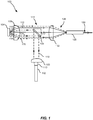
- Fig. 1 illustrates a cross-sectional side view of a light emitting apparatus 100.
- the light emitting apparatus 100 comprises a light source 102, an element 104, a reflector 106, and a lens 108.
- the reflector is a dichroic reflector 106.
- the skilled person in the art realizes that the reflector may in other embodiments be a mirror or a diffractive grating.
- the light source 102 is arranged to emit light of a first wavelength 110.
- a collimating lens 103 is arranged after the light source 102 to provide a collimated beam of light of the first wavelength on the dichroic reflector 106.
- a collimating function can be achieved by a curved reflector such as a parabolic reflector.
- the light source may then be placed in a focus of the parabolic reflector.
- the element 104 is arranged to convert light of the first wavelength 110 into light of a second wavelength 112.
- the element 104 is further arranged to emit the light of the second wavelength 112.
- the element 104 is further arranged to reflect light of the first wavelength 110.
- the dichroic reflector 106 is arranged to reflect light of the first wavelength 110.
- the dichroic reflector 106 is arranged to transmit light of the second wavelength 112.
- Fig. 1 illustrated light of the first wavelength 110 emitted from the light source 102 on the dichroic reflector 106 is reflected and directed towards the element 104.
- the lens 108 is arranged to focus light of the first wavelength 110 onto the element 104.
- the lens 108 is further arranged to collect light emitted and reflected from the element 104.
- the lens 108 may be referred to as a collimating lens providing collimation of the light in the focus of the lens 108, i.e. substantially parallel rays 114 of light may leave the lens 108.
- the lens 103 and the lens 108 are here illustrated as plano-convex lenses but the skilled person in the art realizes that other lenses or mirrors and lens or mirror systems may be used.
- the element 104 is arranged to emit light of the second wavelength 112 with an angular distribution 116 within a collection angle of the lens 108. Light of the second wavelength 112 may thereby be collected by the lens 108 and sent from the lens 108 as collimated light 114 such that light of the second wavelength 112 may be emitted from the light emitting apparatus 100.
- the element 104 is further arranged to reflect light of the first wavelength 110 with an angular distribution 118 substantially within the collection angle of the lens 108.
- the element 104 is further arranged to reflect light of the first wavelength 110 with an intensity distribution such that a portion 120 of the light of the first wavelength 110 that is reflected with an angular distribution 118 outside a region 122 covered by the dichroic reflector 106 is larger than a portion 124 of the light of the first wavelength 110 that is reflected with an angular distribution within the region 122 covered by the dichroic reflector 106.
- the light emitting apparatus 100 may thereby provide an increased light output. By increasing the portion 120 of the light of the first wavelength 110 that is reflected with an angular distribution outside the region 122 covered by the dichroic reflector 106 more light of the first wavelength 110 may be emitted from the light emitting apparatus 100.
- the ratio of the light of the first wavelength 110 and the second wavelength 112 emitted from the light emitting apparatus 100 determines the spectral distribution of the light emitted from the light emitting apparatus 100.
- the color point of the emitted light from the light emitting apparatus 100 may be set to a desired value by tailoring the portions 120 and 124 of light.
- the light emitting apparatus 100 may comprise a mixing element 126.
- the mixing element 126 is arranged to mix light 128 entering the mixing element 126.
- the light 128 entering the mixing chamber originates from the element 104 and may comprise a spatially varying spectral composition, i.e. light of the first 110 and the second 112 wavelength may be separated in space.
- the light 128 that enters the mixing element 126 is mixed spatially by for instance multiple reflections and/or diffraction.
- the light 130 leaving the mixing element 126 may thereby have a spatially more uniform spectral distribution than the light 128 entering the mixing chamber 126.
- a light emitting apparatus 100 providing a spatially more uniform output of light may thereby be obtained.
- the light source 102 may be monochromatic, for instance emitting blue light.
- the light of the first wavelength 110 may be blue light and the light of the second wavelength 112 may have a longer wavelength than the first wavelength 110, such as yellow light.
- a combination of the blue and the yellow light may produce white light.
- the light emitting apparatus 100 may provide white light 130 with a more uniform spectral distribution.
- the white light emitted by the light emitting apparatus 100 may then be made to appear whiter, or otherwise with a different correlated color temperature, i.e. the light is less yellow in color by increasing the amount of blue light of the first wavelength 110.
- the color point of the white light may be set to a predetermined value by adjusting the ratio of light of the first 110 and the second 112 wavelength.
- the mixing member 126 may be an optical fiber. A simple, cost effective and flexible mixing member 126 may thereby be achieved. The light 128 entering the mixing element 126 may further propagate efficiently in the core of the optical fiber by total internal reflection.
- the mixing member may alternatively be a transparent rod.
- the cross-section of the rod or the optical fiber may be non-circular, for instance having a square, hexagonal or octagonal cross-section in order to improve light mixing.
- the light emitting apparatus 100 may further comprise an additional lens 132 arranged to focus light originating from the element 104 and being collected by the additional lens 132 into the mixing member 126. A more efficient coupling of light into the mixing member 126 may thereby be obtained and an increased light output from the light emitting apparatus 100 may be achieved.
- Fig. 2 illustrates a cross-sectional side view of an element 202 suitable to be arranged within the light emitting apparatus 100.
- the element 202 comprises a wavelength converting member 204 and a reflecting member 206.
- the wavelength converting member 204 is arranged to convert light of a first wavelength 110 into light of a second wavelength 112.
- the wavelength converting member 204 is further arranged to emit 208 the light of the second wavelength 112.
- the reflecting member 206 comprises a reflecting surface 210.
- the reflecting member 206 is arranged to reflect light 212 of the first wavelength 110. Efficient redistributing of light is thereby achieved and the light emission from the light emitting apparatus may be increased.
- the reflecting member 206 comprises an inclined surface 214.
- the extension 214 of the inclined surface 214 may determine the amount of light of the first wavelength 110 that is reflected 212, i.e. redirected. A larger extension may result in that a larger portion of the light of the first wavelength 110 that is focused on the element 202 is reflected by the inclined surface 214.
- the angle 218, i.e. the inclination, of the inclined surface 214 determines the angular distribution at which light is reflected at the element 202.
- the angle 218 may be chosen such that the angular distribution of the light reflected 212 by the element 202 has an angular distribution which is outside the region covered by the dichroic reflector 106 of the light emitting apparatus 100.
- the angle 218 may be in the range of 25° to 75°, depending on the collection angle and focal length of the lens 108 or the extension of the dichroic reflector 106. It should be noted that the amount of light of the first wavelength 110 and the amount of light of the second wavelength 112 that is emitted 208 and/or reflected 212 by the element 202 depend on the amount of light of the first wavelength 110 that reach the wavelength converting member 204 and the reflecting member 206, respectively.
- the element 202 may be movable 220 in relation to the lens 108.
- the ratio of the converted/reflected light in interaction with the different surface areas of the element that is illuminated may be changed.
- the larger portion of the light of the first wavelength 110 that reach the reflective surface 210 of the reflecting member 206 the larger is the amount of light of the first wavelength 110 that is reflected 212.
- a larger amount of light of the first wavelength 110 may be emitted by the light emitting apparatus 100.
- the amount of light of the first 110 and the second 112 wavelength that is respectively reflected or emitted from the light emitting apparatus may thereby be changed by moving the element 202.
- the element 202 may be combined with an off-axis position of the dichroic reflector with respect to the center of the beam in order to improve the collection efficiency of the first wavelength 110 further.
- the element may alternatively be also made symmetric such that the wavelength converting member has in its adjacency reflecting members on both sides, both reflecting members having inclined surfaces for angular redistribution of the light being redirected.
- the element may further in this symmetric configuration be arranged in an on-axis position of the dichroic mirror.
- Fig. 3 illustrates a cross-sectional side view of an element 302 suitable to be arranged within the light emitting apparatus 100.
- the element 302 comprises a wavelength converting member 204 and a reflecting member 304.
- the reflecting member 304 is shown to surround the wavelength converting member 204, but the reflecting member 304 may cover only a portion of the area surrounding the wavelength converting member 204.
- the reflecting member 304 comprises a diffraction grating 306.
- Light of the first wavelength 110 which is reflected 308 at the diffraction grating may thereby be reflected with an angular distribution outside a region covered by the dichroic reflector 106. Efficient redirection of light reflected by the element may thereby be obtained.
- the wavelength converting member 204 is arranged to convert light of a first wavelength 110 into light of a second wavelength 112 and emit 310 the light of the second wavelength 112.
- the diffraction grating 306 acts as the dispersive element and the direction of the reflected light depends on the angle at which the light is incident on the grating, on the grating period of the diffraction grating 306 and the wavelength of the incoming light, i.e. the first wavelength. It is known to the skilled person in the art to design a the diffraction angles of the diffraction grating as, for example, the relationship between the grating spacing and the angles of the incident and diffracted beams of light is known by the grating equation.
- the diffraction grating 306 may be a blazed grating.
- the blazed grating is arranged to achieve increased reflection efficiency in a given diffraction order. In other words, improved light output may be achieved in a desired diffraction order while the residual light output in the other orders is reduced.
- the angular direction in which improved efficiency is achieved is given by the blaze angle, the wavelength at which the grating is optimized, i.e. blazed, and the given diffraction order.
- a proper design of the blazed grating may therefore improve the light reflectance of the element 302 in a given diffraction order such that light is efficiently reflected with an angular distribution outside a region covered by the dichroic reflector 106. An increased light output from the light emitting apparatus 106 is thereby achieved.
- the element 302 may comprise a diffraction grating 307 arranged below the wavelength converting member.
- the diffraction grating 307 may be a blazed grating.
- the diffraction grating 307 may reflect light of the first wavelength that has not been converted (not shown) by the wavelength converting member 204.
- the structure of the diffraction grating 307 is similar to the diffraction grating 306 and will for brevity not be discussed further. It should, however, be noted the wavelength of the light of the first wavelength 110 may shift when inside the wavelength converting member 204 due to a change in the refractive index. Hence, the gratings 306 and 307 may differ in their design, e.g. have different grating spacing and blaze angle.
- the element 302 may comprise the diffraction grating 307 and/or the diffraction grating 306.
- a top portion of the wavelength converting member 204 may be shaped into a diffraction grating (not shown) providing efficient reflection and redirection of a portion of light of the first wavelength that reach wavelength converting member 204.
- the wavelength converting member 204 may reflect a portion of the light of the first wavelength 110 and convert another portion of the light of the first wavelength 110 into light of the second wavelength 112. The intensity of light of the first wavelength leaving the wavelength converting member 204 is thereby increased.
- the reflecting member may comprise a scattering element (not shown). Efficient redirection of light reflected by the element may thereby be obtained.
- the reflecting member may also reflect light emitted by the element.
- the reflecting member may comprise optical micro-structures which may be arranged into periodic arrays.
- the individual optical micro-structures may have rotational symmetry resulting in a rotationally symmetric distribution of reflected light.
- the individual optical micro-structures may alternatively have lower symmetry, providing anisotropic angular distribution of reflected light.
- the optical micro-structures may be elongated in one direction and the reflected light may be directed mostly at angles outside the horizontal plane. This can be combined with an elongated reflector 106 located within the horizontal plane, thereby providing effective arrangement for the light of the first wavelength to be directed outside the collecting range of the reflector 106.
- the reflecting member may comprise holographic optical elements.
- the wavelength converting member may comprise a scattering element. Efficient redirection of light reflected and/or emitted by the element may thereby be obtained.
- the scatting material may comprise particles, air inclusions or a structuring of the surface of the wavelength converting member and/or the reflecting member.
- Fig. 4 illustrates a cross-sectional side view of an element 402 suitable to be arranged within the light emitting apparatus 100.
- the element 402 comprises a wavelength converting member 404 having a front surface 406 facing the lens 108.
- the front surface 406 comprises a curved portion 408 pointing outward from the front surface 406.
- Light of the first wavelength 110 that reach the front surface of the wavelength converting member may be reflected and thereby redirected with an angular distribution outside a region covered by the dichroic reflector 106.
- the curvature of the curved portion 408 determines the angles at which the light of the first wavelength are reflected.
- a larger curvature allows for a larger portion of the light of the first wavelength 110 that is incident on the wavelength converting member 404, to be efficiently reflected with an angular distribution outside a region covered by the dichroic reflector 106.
- An increased light output from the light emitting apparatus 100 may thereby be achieved.
- Preferred angles of redirection are in the range of 25° to 75°, depending on the collection angle and focal length of the lens 108 or the extension of the dichroic reflector 106.
- the element 402 may further comprise a reflecting member 410.
- the features of the reflection member 410 have been described above.
- the curved portion 408 of element 402 may be coated with a semi-transparent wavelength selective optical mirror in order to balance the light of the first wavelength 110 that is transmitted and reflected by surface 408.
- the wavelength converting member may comprise a phosphor material such as a ceramic phosphor.
- the ceramic phosphor may be a Ce- or LU-doped YAC ceramic phosphor such as Lumiramic with high thermal conductivity Organic fluorescent dyes and quantum dots which are may also be considered for the purpose of the present invention.
- Quantum dots are small crystals of semiconducting material generally having a width or diameter of only a few nanometers. When excited by incident light, a quantum dot emits light of a color determined by the size and material of the crystal. Light of a particular color can therefore be produced by adapting the size of the dots.
- Most known quantum dots with emission in the visible range are based on cadmium selenide (CdSe) with a shell such as cadmium sulfide (CdS) and zinc sulfide (ZnS).
- Cadmium free quantum dots such as indium phosphide (InP), and copper indium sulfide (CuInS2) and/or silver indium sulfide (AgInS2) can also be used.
- Quantum dots show very narrow emission band and thus they show saturated colors. Furthermore the emission color can easily be tuned by adapting the size of the quantum dots. Any type of quantum dot known in the art may be used in the present invention. However, it may be preferred for reasons of environmental safety and concern to use cadmium-free quantum dots or at least quantum dots having very low cadmium content.
- Organic fluorescent dyes can be used as well.
- the molecular structure can be designed such that the spectral peak position can be tuned.
- suitable organic fluorescent dyes materials are organic luminescent materials based on perylene derivatives, for example compounds sold under the name Lumogen® by BASF.
- suitable compounds include, but are not limited to, Lumogen® Red F305, Lumogen® Orange F240, Lumogen® Yellow F083, and Lumogen® F170.
- the luminescent material may also be an inorganic phosphor.
- inorganic phosphor materials include, but are not limited to, cerium (Ce) doped YAG (Y3Al5O12) or LuAG (Lu3Al5O12). Ce doped YAG emits yellowish light, whereas Ce doped LuAG emits yellow-greenish light.
- Examples of other inorganic phosphors materials which emit red light may include, but are not limited to ECAS and BSSN; ECAS being Cal-xAlSiN3:Eux wherein 0 ⁇ x ⁇ 1, preferably 0 ⁇ x ⁇ 0.2; and BSSN being Ba2-x-zMxSi5-yAlyN8-yOy:Euz wherein M represents Sr or Ca, 0 ⁇ x ⁇ 1, 0 ⁇ y ⁇ 4, and 0.0005 ⁇ z ⁇ 0.05, and preferably 0 ⁇ x ⁇ 0.2.
- the luminescent material is essentially made of material selected from the group comprising (M ⁇ I>1-x-yM ⁇ II>xM ⁇ III>y)3(M ⁇ IV>1-zM ⁇ V>z)5O12- where M ⁇ I >is selected from the group comprising Y, Lu or mixtures thereof, M ⁇ II >is selected from the group comprising Gd, La, Yb or mixtures thereof, M ⁇ III >is selected from the group comprising Tb, Pr, Ce, Er, Nd, Eu or mixtures thereof, M ⁇ IV >is Al, M ⁇ V >is selected from the group comprising Ga, Sc or mixtures thereof, and 0 ⁇ x ⁇ 1, 0 ⁇ y ⁇ 0.1, 0 ⁇ z ⁇ 1,(M ⁇ I>1-x-yM ⁇ II>x,M ⁇ III>y)2O3- where M ⁇ I >is selected from the group comprising Y, Lu or mixtures thereof, M ⁇ II >is selected from the group comprising Gd, La,
- luminescent materials are Ce doped Yttrium aluminum garnet (YAG, Y 3 Al 5 O 12 ) and Lutetium-Aluminum-Garnet (LuAG).
- Thermal conductivity of the phosphor ceramic is preferentially higher than 2 more preferentially more than 6 and most preferentially more than 20 W ⁇ m -1 ⁇ K -1 .
- the reflecting member may comprise a specular- or diffuse-reflecting material such as aluminum or silver.
- the reflecting member may also comprise boron nitride or, aluminum oxide providing refection and improved thermal conductivity providing improved thermal management.
- the reflector is disclosed as a dichroic reflector.
- the skilled person in the art realizes that the reflector may in other embodiments be a mirror or a diffractive grating.
- the element may be arranged to emit and/or reflect light of the second wavelength with an angular distribution substantially within the collection angle of the lens and with an intensity distribution such that a portion of the light of the second wavelength that is emitted and/or reflected with an angular distribution outside a region covered by the reflector is larger than a portion of the light of the second wavelength that is emitted and/or reflected with an angular distribution within the region covered by the reflector.
- the element may comprise a wavelength converting member having a front surface facing the lens, the front surface having a conical shape.
- the reflecting member may reflect light of the second wavelength.
- Light of a first wavelength which is generated by the light source may be partly converted into light of a second wavelength by the wavelength converting member.
- the wavelength converting member may reflect light of the first wavelength.
- a multilayer structure may be arranged below the wavelength converting member. It is thereby possible by multiple reflection and interference to increase the amount of light of the second wavelength that is reflected and redirected such that the light may be collected by the lens.
Landscapes
- Physics & Mathematics (AREA)
- Engineering & Computer Science (AREA)
- General Engineering & Computer Science (AREA)
- Optics & Photonics (AREA)
- General Physics & Mathematics (AREA)
- Spectroscopy & Molecular Physics (AREA)
- Microelectronics & Electronic Packaging (AREA)
- Multimedia (AREA)
- Non-Portable Lighting Devices Or Systems Thereof (AREA)
- Led Device Packages (AREA)
- Diffracting Gratings Or Hologram Optical Elements (AREA)
- Semiconductor Lasers (AREA)
- Optical Filters (AREA)
Claims (13)
- Appareil électroluminescent comprenant :un élément (104, 202, 302, 402) agencé pour transformer la lumière d'une première longueur d'onde (110) en lumière d'une seconde longueur d'onde (112), émettre (208) la lumière de la seconde longueur d'onde (112) et réfléchir (212) la lumière de la première longueur d'onde (110),un réflecteur (106) agencé pour réfléchir la lumière de la première longueur d'onde (110),une source de lumière (102) émettant une lumière de la première longueur d'onde (110) sur le réflecteur (106) de sorte que la lumière réfléchie de la première longueur d'onde (110) est dirigée vers l'élément (104, 202, 302, 402),une lentille (108) agencé pour concentrer la lumière de la première longueur d'onde (110) réfléchie par le réflecteur (106) sur l'élément (104, 202, 302, 402), et pour collecter la lumière émise (208) et réfléchie (212) à partir de l'élément (104, 202, 302, 402),dans lequel l'élément (104, 202, 302, 402) est agencé pour émettre la lumière de la seconde longueur d'onde (112) avec une distribution angulaire (116) à l'intérieur d'un angle de collection de la lentille (108),dans lequel l'élément (104, 202, 302, 402) est en outre agencé pour réfléchir la lumière de la première longueur d'onde (110) avec une distribution angulaire (118) sensiblement à l'intérieur de l'angle de collection de la lentille (108) et avec une distribution d'intensité de sorte qu'une portion (120) de la lumière de la première longueur d'onde (110) qui est réfléchie avec une distribution angulaire à l'extérieur d'une région (122) couverte par le réflecteur (106) est plus grande qu'une portion (124) de la lumière de la première longueur d'onde (110) qui est réfléchie avec une distribution angulaire à l'intérieur de la région (122) couverte par le réflecteur (106),dans lequel l'élément (202, 302, 402) comprend un élément de transformation de longueur d'onde (204, 404) et un élément réfléchissant (206, 304, 410),et dans lequel l'élément (104, 202, 302, 402) est mobile par rapport au plan focal de la lentille (108).
- Appareil électroluminescent selon la revendication 1, dans lequel la portion (120) de la lumière de la première longueur d'onde (110) qui est réfléchie avec la distribution angulaire à l'extérieur d'une région (122) couverte par le réflecteur (106) est au moins 50 % plus grande, ou plus de préférence 70 % plus grande et même plus de préférence 90 % plus grande que la portion (124) de la lumière de la première longueur d'onde (110) qui est réfléchie avec la distribution angulaire à l'intérieur de la région (122) couverte par le réflecteur (106).
- Appareil électroluminescent selon l'une quelconque des revendications 1 à 2, dans lequel l'élément (302) comprend en outre un réseau de diffraction (306, 307).
- Appareil électroluminescent selon la revendication 1, dans lequel l'élément réfléchissant (304) comprend le réseau de diffraction (306).
- Appareil électroluminescent selon la revendication 1, dans lequel l'élément réfléchissant (206) comprend une surface inclinée (214).
- Appareil électroluminescent selon la revendication 1, dans lequel l'élément réfléchissant comprend un élément dispersant.
- Appareil électroluminescent selon l'une quelconque des revendications 1 à 6, dans lequel l'élément de transformation de longueur d'onde (404) a une surface avant (406) faisant face à la lentille (108), la surface avant (406) comprenant une portion incurvée (408) pointant à l'extérieur de la surface avant (406).
- Appareil électroluminescent selon la revendication 1, dans lequel l'élément de transformation de longueur d'onde comprend un élément dispersant.
- Appareil électroluminescent selon l'une quelconque des revendications 1 à 8, dans lequel l'appareil électroluminescent (100) comprend en outre un élément mélangeur (126) agencé pour mélanger la lumière, provenant de l'élément (104, 202, 302, 402) et étant collectée par la lentille (108), de sorte que la lumière de la première longueur d'onde (110) et la lumière de la seconde longueur d'onde (112) sont mélangées à l'intérieur de l'élément mélangeur (126).
- Appareil électroluminescent selon la revendication 9, dans lequel l'élément mélangeur (126) est une fibre optique.
- Appareil électroluminescent selon la revendication 9 ou 10, dans lequel l'appareil électroluminescent (100) comprend en outre une lentille supplémentaire (132) agencée pour concentrer la lumière, provenant de l'élément (104, 202, 302, 402) et étant collectée par la lentille (108), dans l'élément mélangeur (126) après que la lumière a quitté la lentille (108).
- Appareil électroluminescent selon l'une quelconque des revendications 1 à 11, dans lequel la source de lumière est monochromatique.
- Appareil électroluminescent selon l'une quelconque des revendications 1 à 12, dans lequel la source de lumière (102) comprend une diode laser et/ou une diode électroluminescente.
Applications Claiming Priority (2)
| Application Number | Priority Date | Filing Date | Title |
|---|---|---|---|
| EP15157710 | 2015-03-05 | ||
| PCT/EP2016/052973 WO2016139046A1 (fr) | 2015-03-05 | 2016-02-12 | Appareil électroluminescent |
Publications (2)
| Publication Number | Publication Date |
|---|---|
| EP3265719A1 EP3265719A1 (fr) | 2018-01-10 |
| EP3265719B1 true EP3265719B1 (fr) | 2018-09-19 |
Family
ID=52669477
Family Applications (1)
| Application Number | Title | Priority Date | Filing Date |
|---|---|---|---|
| EP16704433.8A Not-in-force EP3265719B1 (fr) | 2015-03-05 | 2016-02-12 | Appareil électroluminescent |
Country Status (5)
| Country | Link |
|---|---|
| US (1) | US10317045B2 (fr) |
| EP (1) | EP3265719B1 (fr) |
| JP (1) | JP2018510467A (fr) |
| CN (1) | CN107429900B (fr) |
| WO (1) | WO2016139046A1 (fr) |
Families Citing this family (7)
| Publication number | Priority date | Publication date | Assignee | Title |
|---|---|---|---|---|
| US10494357B2 (en) * | 2015-08-27 | 2019-12-03 | Université d'Angers | Tocotrienol derivatives, pharmaceutical composition and method of use in 5-lipoxygenase related diseases |
| CN108761981B (zh) * | 2018-04-28 | 2020-10-20 | 苏州佳世达光电有限公司 | 投影机 |
| CN110412817B (zh) * | 2018-04-28 | 2024-05-03 | 中强光电股份有限公司 | 投影装置以及照明系统 |
| DE102018128743A1 (de) | 2018-11-15 | 2020-05-20 | Carl Zeiss Jena Gmbh | Beleuchtungsvorrichtung für einen einen Lichtmodulator aufweisenden Projektor |
| CN112213908B (zh) * | 2019-07-12 | 2022-12-02 | 深圳光峰科技股份有限公司 | 光源系统与显示设备 |
| JP7484130B2 (ja) * | 2019-11-01 | 2024-05-16 | セイコーエプソン株式会社 | 波長変換素子、光源装置およびプロジェクター |
| WO2024083732A1 (fr) * | 2022-10-18 | 2024-04-25 | Signify Holding B.V. | Agencement d'éclairage comprenant une source de lumière laser |
Family Cites Families (12)
| Publication number | Priority date | Publication date | Assignee | Title |
|---|---|---|---|---|
| JP5007654B2 (ja) * | 2007-11-16 | 2012-08-22 | 岩崎電気株式会社 | 光源装置 |
| JP2011128482A (ja) * | 2009-12-21 | 2011-06-30 | Seiko Epson Corp | 照明装置及びプロジェクター |
| WO2012075949A1 (fr) * | 2010-12-08 | 2012-06-14 | 绎立锐光科技开发(深圳)有限公司 | Source lumineuse |
| EP2466375B1 (fr) | 2010-12-17 | 2019-12-25 | Maxell, Ltd. | Appareil de source lumineuse |
| JP5675320B2 (ja) * | 2010-12-17 | 2015-02-25 | 日立マクセル株式会社 | 光源装置、および、投写型映像表示装置 |
| CN103403438A (zh) * | 2011-03-01 | 2013-11-20 | 欧司朗股份有限公司 | 具有荧光元件的照明设备 |
| US9816683B2 (en) * | 2011-10-20 | 2017-11-14 | Appotronics Corporation Limited | Light sources system and projection device using the same |
| TW201405048A (zh) | 2012-07-19 | 2014-02-01 | 瓦維安股份有限公司 | 用於投影顯示器之基於磷光體的燈具 |
| JP2014075221A (ja) * | 2012-10-03 | 2014-04-24 | Mitsubishi Electric Corp | 光源装置 |
| JP5997077B2 (ja) * | 2013-03-07 | 2016-09-21 | 日立マクセル株式会社 | 光源装置 |
| JP6232818B2 (ja) * | 2013-03-15 | 2017-11-22 | セイコーエプソン株式会社 | 照明装置及びプロジェクター |
| US9648291B2 (en) | 2013-04-22 | 2017-05-09 | Hitachi Maxell, Ltd. | Light source device and projection type image display device |
-
2016
- 2016-02-12 EP EP16704433.8A patent/EP3265719B1/fr not_active Not-in-force
- 2016-02-12 JP JP2017546128A patent/JP2018510467A/ja active Pending
- 2016-02-12 WO PCT/EP2016/052973 patent/WO2016139046A1/fr active Application Filing
- 2016-02-12 US US15/554,151 patent/US10317045B2/en not_active Expired - Fee Related
- 2016-02-12 CN CN201680013648.XA patent/CN107429900B/zh not_active Expired - Fee Related
Non-Patent Citations (1)
| Title |
|---|
| None * |
Also Published As
| Publication number | Publication date |
|---|---|
| CN107429900B (zh) | 2020-09-25 |
| JP2018510467A (ja) | 2018-04-12 |
| CN107429900A (zh) | 2017-12-01 |
| US20180038574A1 (en) | 2018-02-08 |
| WO2016139046A1 (fr) | 2016-09-09 |
| EP3265719A1 (fr) | 2018-01-10 |
| US10317045B2 (en) | 2019-06-11 |
Similar Documents
| Publication | Publication Date | Title |
|---|---|---|
| EP3265719B1 (fr) | Appareil électroluminescent | |
| EP3078898B1 (fr) | Appareil emetteur de lumiere a haute luminosite | |
| JP6722700B2 (ja) | 高輝度光を作り出す光学デバイス | |
| JP6165361B2 (ja) | 発光デバイス | |
| CN107208853B (zh) | 高强度白光源 | |
| JP2016537770A (ja) | 発光デバイス | |
| CN106469770B (zh) | 发光装置 | |
| JP6466467B2 (ja) | スペクトル変換要素を備える発光デバイス | |
| RU2689122C1 (ru) | Светоизлучающее устройство |
Legal Events
| Date | Code | Title | Description |
|---|---|---|---|
| STAA | Information on the status of an ep patent application or granted ep patent |
Free format text: STATUS: THE INTERNATIONAL PUBLICATION HAS BEEN MADE |
|
| PUAI | Public reference made under article 153(3) epc to a published international application that has entered the european phase |
Free format text: ORIGINAL CODE: 0009012 |
|
| STAA | Information on the status of an ep patent application or granted ep patent |
Free format text: STATUS: REQUEST FOR EXAMINATION WAS MADE |
|
| 17P | Request for examination filed |
Effective date: 20171005 |
|
| AK | Designated contracting states |
Kind code of ref document: A1 Designated state(s): AL AT BE BG CH CY CZ DE DK EE ES FI FR GB GR HR HU IE IS IT LI LT LU LV MC MK MT NL NO PL PT RO RS SE SI SK SM TR |
|
| AX | Request for extension of the european patent |
Extension state: BA ME |
|
| REG | Reference to a national code |
Ref country code: DE Ref legal event code: R079 Ref document number: 602016005769 Country of ref document: DE Free format text: PREVIOUS MAIN CLASS: F21K0099000000 Ipc: F21V0009400000 |
|
| RIC1 | Information provided on ipc code assigned before grant |
Ipc: F21V 9/40 20180101AFI20180307BHEP |
|
| GRAP | Despatch of communication of intention to grant a patent |
Free format text: ORIGINAL CODE: EPIDOSNIGR1 |
|
| STAA | Information on the status of an ep patent application or granted ep patent |
Free format text: STATUS: GRANT OF PATENT IS INTENDED |
|
| DAX | Request for extension of the european patent (deleted) | ||
| INTG | Intention to grant announced |
Effective date: 20180420 |
|
| DAV | Request for validation of the european patent (deleted) | ||
| GRAS | Grant fee paid |
Free format text: ORIGINAL CODE: EPIDOSNIGR3 |
|
| GRAA | (expected) grant |
Free format text: ORIGINAL CODE: 0009210 |
|
| STAA | Information on the status of an ep patent application or granted ep patent |
Free format text: STATUS: THE PATENT HAS BEEN GRANTED |
|
| AK | Designated contracting states |
Kind code of ref document: B1 Designated state(s): AL AT BE BG CH CY CZ DE DK EE ES FI FR GB GR HR HU IE IS IT LI LT LU LV MC MK MT NL NO PL PT RO RS SE SI SK SM TR |
|
| REG | Reference to a national code |
Ref country code: GB Ref legal event code: FG4D |
|
| REG | Reference to a national code |
Ref country code: CH Ref legal event code: EP |
|
| REG | Reference to a national code |
Ref country code: AT Ref legal event code: REF Ref document number: 1043652 Country of ref document: AT Kind code of ref document: T Effective date: 20181015 |
|
| REG | Reference to a national code |
Ref country code: IE Ref legal event code: FG4D |
|
| REG | Reference to a national code |
Ref country code: DE Ref legal event code: R096 Ref document number: 602016005769 Country of ref document: DE |
|
| RAP2 | Party data changed (patent owner data changed or rights of a patent transferred) |
Owner name: PHILIPS LIGHTING HOLDING B.V. |
|
| REG | Reference to a national code |
Ref country code: NL Ref legal event code: MP Effective date: 20180919 |
|
| PG25 | Lapsed in a contracting state [announced via postgrant information from national office to epo] |
Ref country code: GR Free format text: LAPSE BECAUSE OF FAILURE TO SUBMIT A TRANSLATION OF THE DESCRIPTION OR TO PAY THE FEE WITHIN THE PRESCRIBED TIME-LIMIT Effective date: 20181220 Ref country code: FI Free format text: LAPSE BECAUSE OF FAILURE TO SUBMIT A TRANSLATION OF THE DESCRIPTION OR TO PAY THE FEE WITHIN THE PRESCRIBED TIME-LIMIT Effective date: 20180919 Ref country code: RS Free format text: LAPSE BECAUSE OF FAILURE TO SUBMIT A TRANSLATION OF THE DESCRIPTION OR TO PAY THE FEE WITHIN THE PRESCRIBED TIME-LIMIT Effective date: 20180919 Ref country code: NO Free format text: LAPSE BECAUSE OF FAILURE TO SUBMIT A TRANSLATION OF THE DESCRIPTION OR TO PAY THE FEE WITHIN THE PRESCRIBED TIME-LIMIT Effective date: 20181219 Ref country code: SE Free format text: LAPSE BECAUSE OF FAILURE TO SUBMIT A TRANSLATION OF THE DESCRIPTION OR TO PAY THE FEE WITHIN THE PRESCRIBED TIME-LIMIT Effective date: 20180919 Ref country code: BG Free format text: LAPSE BECAUSE OF FAILURE TO SUBMIT A TRANSLATION OF THE DESCRIPTION OR TO PAY THE FEE WITHIN THE PRESCRIBED TIME-LIMIT Effective date: 20181219 Ref country code: LT Free format text: LAPSE BECAUSE OF FAILURE TO SUBMIT A TRANSLATION OF THE DESCRIPTION OR TO PAY THE FEE WITHIN THE PRESCRIBED TIME-LIMIT Effective date: 20180919 |
|
| REG | Reference to a national code |
Ref country code: CH Ref legal event code: PK Free format text: BERICHTIGUNGEN |
|
| REG | Reference to a national code |
Ref country code: LT Ref legal event code: MG4D |
|
| RIC2 | Information provided on ipc code assigned after grant |
Ipc: F21V 9/40 20180101AFI20180307BHEP |
|
| PG25 | Lapsed in a contracting state [announced via postgrant information from national office to epo] |
Ref country code: AL Free format text: LAPSE BECAUSE OF FAILURE TO SUBMIT A TRANSLATION OF THE DESCRIPTION OR TO PAY THE FEE WITHIN THE PRESCRIBED TIME-LIMIT Effective date: 20180919 Ref country code: LV Free format text: LAPSE BECAUSE OF FAILURE TO SUBMIT A TRANSLATION OF THE DESCRIPTION OR TO PAY THE FEE WITHIN THE PRESCRIBED TIME-LIMIT Effective date: 20180919 Ref country code: HR Free format text: LAPSE BECAUSE OF FAILURE TO SUBMIT A TRANSLATION OF THE DESCRIPTION OR TO PAY THE FEE WITHIN THE PRESCRIBED TIME-LIMIT Effective date: 20180919 |
|
| RAP2 | Party data changed (patent owner data changed or rights of a patent transferred) |
Owner name: SIGNIFY HOLDING B.V. |
|
| REG | Reference to a national code |
Ref country code: AT Ref legal event code: MK05 Ref document number: 1043652 Country of ref document: AT Kind code of ref document: T Effective date: 20180919 |
|
| PG25 | Lapsed in a contracting state [announced via postgrant information from national office to epo] |
Ref country code: ES Free format text: LAPSE BECAUSE OF FAILURE TO SUBMIT A TRANSLATION OF THE DESCRIPTION OR TO PAY THE FEE WITHIN THE PRESCRIBED TIME-LIMIT Effective date: 20180919 Ref country code: PL Free format text: LAPSE BECAUSE OF FAILURE TO SUBMIT A TRANSLATION OF THE DESCRIPTION OR TO PAY THE FEE WITHIN THE PRESCRIBED TIME-LIMIT Effective date: 20180919 Ref country code: IS Free format text: LAPSE BECAUSE OF FAILURE TO SUBMIT A TRANSLATION OF THE DESCRIPTION OR TO PAY THE FEE WITHIN THE PRESCRIBED TIME-LIMIT Effective date: 20190119 Ref country code: NL Free format text: LAPSE BECAUSE OF FAILURE TO SUBMIT A TRANSLATION OF THE DESCRIPTION OR TO PAY THE FEE WITHIN THE PRESCRIBED TIME-LIMIT Effective date: 20180919 Ref country code: CZ Free format text: LAPSE BECAUSE OF FAILURE TO SUBMIT A TRANSLATION OF THE DESCRIPTION OR TO PAY THE FEE WITHIN THE PRESCRIBED TIME-LIMIT Effective date: 20180919 Ref country code: IT Free format text: LAPSE BECAUSE OF FAILURE TO SUBMIT A TRANSLATION OF THE DESCRIPTION OR TO PAY THE FEE WITHIN THE PRESCRIBED TIME-LIMIT Effective date: 20180919 Ref country code: RO Free format text: LAPSE BECAUSE OF FAILURE TO SUBMIT A TRANSLATION OF THE DESCRIPTION OR TO PAY THE FEE WITHIN THE PRESCRIBED TIME-LIMIT Effective date: 20180919 Ref country code: EE Free format text: LAPSE BECAUSE OF FAILURE TO SUBMIT A TRANSLATION OF THE DESCRIPTION OR TO PAY THE FEE WITHIN THE PRESCRIBED TIME-LIMIT Effective date: 20180919 Ref country code: AT Free format text: LAPSE BECAUSE OF FAILURE TO SUBMIT A TRANSLATION OF THE DESCRIPTION OR TO PAY THE FEE WITHIN THE PRESCRIBED TIME-LIMIT Effective date: 20180919 |
|
| PG25 | Lapsed in a contracting state [announced via postgrant information from national office to epo] |
Ref country code: SM Free format text: LAPSE BECAUSE OF FAILURE TO SUBMIT A TRANSLATION OF THE DESCRIPTION OR TO PAY THE FEE WITHIN THE PRESCRIBED TIME-LIMIT Effective date: 20180919 Ref country code: SK Free format text: LAPSE BECAUSE OF FAILURE TO SUBMIT A TRANSLATION OF THE DESCRIPTION OR TO PAY THE FEE WITHIN THE PRESCRIBED TIME-LIMIT Effective date: 20180919 Ref country code: PT Free format text: LAPSE BECAUSE OF FAILURE TO SUBMIT A TRANSLATION OF THE DESCRIPTION OR TO PAY THE FEE WITHIN THE PRESCRIBED TIME-LIMIT Effective date: 20190119 |
|
| REG | Reference to a national code |
Ref country code: DE Ref legal event code: R097 Ref document number: 602016005769 Country of ref document: DE |
|
| PLBE | No opposition filed within time limit |
Free format text: ORIGINAL CODE: 0009261 |
|
| STAA | Information on the status of an ep patent application or granted ep patent |
Free format text: STATUS: NO OPPOSITION FILED WITHIN TIME LIMIT |
|
| PG25 | Lapsed in a contracting state [announced via postgrant information from national office to epo] |
Ref country code: DK Free format text: LAPSE BECAUSE OF FAILURE TO SUBMIT A TRANSLATION OF THE DESCRIPTION OR TO PAY THE FEE WITHIN THE PRESCRIBED TIME-LIMIT Effective date: 20180919 |
|
| 26N | No opposition filed |
Effective date: 20190620 |
|
| REG | Reference to a national code |
Ref country code: CH Ref legal event code: PL |
|
| PG25 | Lapsed in a contracting state [announced via postgrant information from national office to epo] |
Ref country code: MC Free format text: LAPSE BECAUSE OF FAILURE TO SUBMIT A TRANSLATION OF THE DESCRIPTION OR TO PAY THE FEE WITHIN THE PRESCRIBED TIME-LIMIT Effective date: 20180919 Ref country code: LU Free format text: LAPSE BECAUSE OF NON-PAYMENT OF DUE FEES Effective date: 20190212 |
|
| REG | Reference to a national code |
Ref country code: BE Ref legal event code: MM Effective date: 20190228 |
|
| REG | Reference to a national code |
Ref country code: IE Ref legal event code: MM4A |
|
| PG25 | Lapsed in a contracting state [announced via postgrant information from national office to epo] |
Ref country code: LI Free format text: LAPSE BECAUSE OF NON-PAYMENT OF DUE FEES Effective date: 20190228 Ref country code: CH Free format text: LAPSE BECAUSE OF NON-PAYMENT OF DUE FEES Effective date: 20190228 |
|
| PG25 | Lapsed in a contracting state [announced via postgrant information from national office to epo] |
Ref country code: IE Free format text: LAPSE BECAUSE OF NON-PAYMENT OF DUE FEES Effective date: 20190212 |
|
| PG25 | Lapsed in a contracting state [announced via postgrant information from national office to epo] |
Ref country code: BE Free format text: LAPSE BECAUSE OF NON-PAYMENT OF DUE FEES Effective date: 20190228 |
|
| PG25 | Lapsed in a contracting state [announced via postgrant information from national office to epo] |
Ref country code: TR Free format text: LAPSE BECAUSE OF FAILURE TO SUBMIT A TRANSLATION OF THE DESCRIPTION OR TO PAY THE FEE WITHIN THE PRESCRIBED TIME-LIMIT Effective date: 20180919 |
|
| PG25 | Lapsed in a contracting state [announced via postgrant information from national office to epo] |
Ref country code: MT Free format text: LAPSE BECAUSE OF NON-PAYMENT OF DUE FEES Effective date: 20190212 |
|
| REG | Reference to a national code |
Ref country code: DE Ref legal event code: R081 Ref document number: 602016005769 Country of ref document: DE Owner name: SIGNIFY HOLDING B.V., NL Free format text: FORMER OWNER: PHILIPS LIGHTING HOLDING B.V., EINDHOVEN, NL |
|
| PGFP | Annual fee paid to national office [announced via postgrant information from national office to epo] |
Ref country code: FR Payment date: 20210223 Year of fee payment: 6 |
|
| PG25 | Lapsed in a contracting state [announced via postgrant information from national office to epo] |
Ref country code: CY Free format text: LAPSE BECAUSE OF FAILURE TO SUBMIT A TRANSLATION OF THE DESCRIPTION OR TO PAY THE FEE WITHIN THE PRESCRIBED TIME-LIMIT Effective date: 20180919 |
|
| PGFP | Annual fee paid to national office [announced via postgrant information from national office to epo] |
Ref country code: DE Payment date: 20210225 Year of fee payment: 6 Ref country code: GB Payment date: 20210223 Year of fee payment: 6 |
|
| PG25 | Lapsed in a contracting state [announced via postgrant information from national office to epo] |
Ref country code: HU Free format text: LAPSE BECAUSE OF FAILURE TO SUBMIT A TRANSLATION OF THE DESCRIPTION OR TO PAY THE FEE WITHIN THE PRESCRIBED TIME-LIMIT; INVALID AB INITIO Effective date: 20160212 |
|
| PG25 | Lapsed in a contracting state [announced via postgrant information from national office to epo] |
Ref country code: SI Free format text: LAPSE BECAUSE OF FAILURE TO SUBMIT A TRANSLATION OF THE DESCRIPTION OR TO PAY THE FEE WITHIN THE PRESCRIBED TIME-LIMIT Effective date: 20180919 |
|
| PG25 | Lapsed in a contracting state [announced via postgrant information from national office to epo] |
Ref country code: MK Free format text: LAPSE BECAUSE OF FAILURE TO SUBMIT A TRANSLATION OF THE DESCRIPTION OR TO PAY THE FEE WITHIN THE PRESCRIBED TIME-LIMIT Effective date: 20180919 |
|
| REG | Reference to a national code |
Ref country code: DE Ref legal event code: R119 Ref document number: 602016005769 Country of ref document: DE |
|
| GBPC | Gb: european patent ceased through non-payment of renewal fee |
Effective date: 20220212 |
|
| PG25 | Lapsed in a contracting state [announced via postgrant information from national office to epo] |
Ref country code: FR Free format text: LAPSE BECAUSE OF NON-PAYMENT OF DUE FEES Effective date: 20220228 |
|
| PG25 | Lapsed in a contracting state [announced via postgrant information from national office to epo] |
Ref country code: GB Free format text: LAPSE BECAUSE OF NON-PAYMENT OF DUE FEES Effective date: 20220212 Ref country code: DE Free format text: LAPSE BECAUSE OF NON-PAYMENT OF DUE FEES Effective date: 20220901 |