EP3265332B1 - System for immobilising a removable cartridge in a housing - Google Patents
System for immobilising a removable cartridge in a housing Download PDFInfo
- Publication number
- EP3265332B1 EP3265332B1 EP16701130.3A EP16701130A EP3265332B1 EP 3265332 B1 EP3265332 B1 EP 3265332B1 EP 16701130 A EP16701130 A EP 16701130A EP 3265332 B1 EP3265332 B1 EP 3265332B1
- Authority
- EP
- European Patent Office
- Prior art keywords
- cartridge
- housing
- bar
- trigger
- assembly according
- Prior art date
- Legal status (The legal status is an assumption and is not a legal conclusion. Google has not performed a legal analysis and makes no representation as to the accuracy of the status listed.)
- Active
Links
- 230000000903 blocking effect Effects 0.000 claims description 16
- 238000009792 diffusion process Methods 0.000 claims description 16
- 239000003039 volatile agent Substances 0.000 claims description 9
- 238000000605 extraction Methods 0.000 claims description 5
- 230000003100 immobilizing effect Effects 0.000 claims description 5
- 238000003780 insertion Methods 0.000 claims description 5
- 230000037431 insertion Effects 0.000 claims description 5
- 239000003205 fragrance Substances 0.000 description 36
- 230000007246 mechanism Effects 0.000 description 10
- 230000008859 change Effects 0.000 description 5
- 239000000758 substrate Substances 0.000 description 5
- 230000005540 biological transmission Effects 0.000 description 4
- 238000004891 communication Methods 0.000 description 4
- 150000001875 compounds Chemical class 0.000 description 4
- 238000009423 ventilation Methods 0.000 description 4
- 230000009467 reduction Effects 0.000 description 3
- 208000031968 Cadaver Diseases 0.000 description 2
- 238000004378 air conditioning Methods 0.000 description 2
- 239000011324 bead Substances 0.000 description 2
- 239000003795 chemical substances by application Substances 0.000 description 2
- 235000021183 entrée Nutrition 0.000 description 2
- 230000004907 flux Effects 0.000 description 2
- 238000010438 heat treatment Methods 0.000 description 2
- 238000012423 maintenance Methods 0.000 description 2
- 238000011144 upstream manufacturing Methods 0.000 description 2
- 241000208125 Nicotiana Species 0.000 description 1
- 235000002637 Nicotiana tabacum Nutrition 0.000 description 1
- 241000920340 Pion Species 0.000 description 1
- 230000000694 effects Effects 0.000 description 1
- 238000001914 filtration Methods 0.000 description 1
- 230000000873 masking effect Effects 0.000 description 1
- 239000000463 material Substances 0.000 description 1
- 239000002304 perfume Substances 0.000 description 1
- BASFCYQUMIYNBI-UHFFFAOYSA-N platinum Chemical compound [Pt] BASFCYQUMIYNBI-UHFFFAOYSA-N 0.000 description 1
- 230000001360 synchronised effect Effects 0.000 description 1
- 235000019640 taste Nutrition 0.000 description 1
- 230000007704 transition Effects 0.000 description 1
Images


Classifications
-
- B—PERFORMING OPERATIONS; TRANSPORTING
- B60—VEHICLES IN GENERAL
- B60H—ARRANGEMENTS OF HEATING, COOLING, VENTILATING OR OTHER AIR-TREATING DEVICES SPECIALLY ADAPTED FOR PASSENGER OR GOODS SPACES OF VEHICLES
- B60H3/00—Other air-treating devices
- B60H3/0007—Adding substances other than water to the air, e.g. perfume, oxygen
- B60H3/0035—Adding substances other than water to the air, e.g. perfume, oxygen characterised by the control methods for adding the substance
-
- A—HUMAN NECESSITIES
- A61—MEDICAL OR VETERINARY SCIENCE; HYGIENE
- A61L—METHODS OR APPARATUS FOR STERILISING MATERIALS OR OBJECTS IN GENERAL; DISINFECTION, STERILISATION OR DEODORISATION OF AIR; CHEMICAL ASPECTS OF BANDAGES, DRESSINGS, ABSORBENT PADS OR SURGICAL ARTICLES; MATERIALS FOR BANDAGES, DRESSINGS, ABSORBENT PADS OR SURGICAL ARTICLES
- A61L9/00—Disinfection, sterilisation or deodorisation of air
- A61L9/015—Disinfection, sterilisation or deodorisation of air using gaseous or vaporous substances, e.g. ozone
- A61L9/04—Disinfection, sterilisation or deodorisation of air using gaseous or vaporous substances, e.g. ozone using substances evaporated in the air without heating
- A61L9/12—Apparatus, e.g. holders, therefor
-
- A—HUMAN NECESSITIES
- A61—MEDICAL OR VETERINARY SCIENCE; HYGIENE
- A61L—METHODS OR APPARATUS FOR STERILISING MATERIALS OR OBJECTS IN GENERAL; DISINFECTION, STERILISATION OR DEODORISATION OF AIR; CHEMICAL ASPECTS OF BANDAGES, DRESSINGS, ABSORBENT PADS OR SURGICAL ARTICLES; MATERIALS FOR BANDAGES, DRESSINGS, ABSORBENT PADS OR SURGICAL ARTICLES
- A61L2209/00—Aspects relating to disinfection, sterilisation or deodorisation of air
- A61L2209/10—Apparatus features
- A61L2209/13—Dispensing or storing means for active compounds
- A61L2209/133—Replaceable cartridges, refills
-
- A—HUMAN NECESSITIES
- A61—MEDICAL OR VETERINARY SCIENCE; HYGIENE
- A61L—METHODS OR APPARATUS FOR STERILISING MATERIALS OR OBJECTS IN GENERAL; DISINFECTION, STERILISATION OR DEODORISATION OF AIR; CHEMICAL ASPECTS OF BANDAGES, DRESSINGS, ABSORBENT PADS OR SURGICAL ARTICLES; MATERIALS FOR BANDAGES, DRESSINGS, ABSORBENT PADS OR SURGICAL ARTICLES
- A61L2209/00—Aspects relating to disinfection, sterilisation or deodorisation of air
- A61L2209/10—Apparatus features
- A61L2209/15—Supporting means, e.g. stands, hooks, holes for hanging
-
- A—HUMAN NECESSITIES
- A61—MEDICAL OR VETERINARY SCIENCE; HYGIENE
- A61L—METHODS OR APPARATUS FOR STERILISING MATERIALS OR OBJECTS IN GENERAL; DISINFECTION, STERILISATION OR DEODORISATION OF AIR; CHEMICAL ASPECTS OF BANDAGES, DRESSINGS, ABSORBENT PADS OR SURGICAL ARTICLES; MATERIALS FOR BANDAGES, DRESSINGS, ABSORBENT PADS OR SURGICAL ARTICLES
- A61L2209/00—Aspects relating to disinfection, sterilisation or deodorisation of air
- A61L2209/10—Apparatus features
- A61L2209/16—Connections to a HVAC unit
Definitions
- the present invention relates to a system for immobilizing a removable cartridge in a casing, in particular intended for use in a delivery device forming part of a motor vehicle.
- Devices comprising a housing and provided with a removable cartridge and a button for locking said removable element relative to the housing are known.
- the object of the invention is to improve the situation and to this end proposes an assembly comprising a system for immobilizing a removable cartridge in a housing and said removable cartridge, according to the characteristics of claim 1.
- the immobilization system of the cartridge according to the invention comprises trigger, allowing in a first position, the maintenance of said cartridge in said housing, and in a second position, the introduction/extraction of said cartridge relative to said housing, said trigger being operable in translation in a direction transverse to an insertion/extraction direction of the cartridge.
- said trigger comprises a bar for blocking the cartridge, said bar comprising at least one abutment for blocking the cartridge, the said abutment(s) being intended to cooperate with one or more blocking pins of the said cartridge. , the said blocking pin(s) being provided with a cutaway intended to cause an actuation in translation of the bar during the introduction of the cartridge.
- the invention also relates to a broadcasting device comprising an assembly as described above.
- the invention relates to a system for immobilizing a removable cartridge in a housing, in particular for a diffusion device allowing the treatment of an air flow using volatile agents, especially fragrances.
- the volatile agents in particular the fragrances, comprise a substrate, in particular beads, loaded with volatile compound(s). It may in particular be fragrant balls.
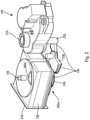
- the diffusion device or diffuser is illustrated as a whole. It comprises here a housing 100 on which two orifices serve as inlet 105 and outlet 110 of the air. From then on, the housing serves as an air guide and includes a plurality of components that will allow air to flow through the case. Preferably, an interface on the orifices 105, 110 allows tubing, not shown, to be attached thereto while ensuring the airtightness of the system.
- the diffuser comprises a cartridge 130 of fragrances and a selector, here housed in said housing 100.
- the selector comprises, for example, an input selector 125a, an output selector 125b and a movable shaft 135 driving them.
- Said diffuser further comprises here an actuation mechanism 150, allowing said shaft 135 to be driven.
- the box 100 can be fixed at different locations of the vehicle, preferably on the dashboard or in the glove box so that the latter is easily accessible to the passenger.
- the cartridge is removable relative to said housing and it is advantageous for the passenger to be able to easily change the cartridge.
- the air outlet of the box 110 is connected, for example, to a grille through which the treated or scented air exits.
- This grille can be attached to different locations in the vehicle. Preferably, it is located on the dashboard or near the ventilation systems of the windshield, the grid being connected to the outlet of the housing by the pipe already mentioned.
- the box 100 comprises a base 180, for example a rectangular parallelepiped.
- a pulser 115 located above the inlet 105 of the housing and at least part of the actuating mechanism 150.
- Said actuating mechanism may comprise a motor 140.
- the latter is fixed to the housing 100 above the pulser 115, and is located outside the housing.
- a second part of the housing 170 has a substantially cubic shape to house the fragrance selector and the cartridge 130 therein. housing parts are assembled together. Airtightness is ensured throughout the housing.
- the inlet 105 is therefore in the base 180 of the housing 100, on the lower face and below the pulser 115.
- the outlet orifice 110 is on the upper face of the second part 170, above the selector output 125b.
- This blower generates the air flow which will finally leave the box through the outlet orifice 110 after passing through the cartridge. 130.
- Airflow is illustrated by line 120 on the figure 1 .
- the pulser 115 is of the radial type, but it can also be of the axial type.
- the cartridge 130 is advantageously composed of a plurality of cavities in which different fragrances can be housed.
- the selector 125a, 125b is configured so that one or more of these cavities are crossed by the flow of air so that the latter is charged with the volatile compounds of the fragrance(s) selected.
- the air flow passes through said selected cavity or cavities, the air comes into contact with all of the substrate contained in each of said cavities and said substrate releases the compound or compounds which will perfume and/or treat the flow. of air, and then the passenger compartment of the motor vehicle.
- the air flow 120 enters the cartridge 130 through an input of the input selector.
- the air flow then crosses the cartridge 130 right through passing through one or more of the cavities of said cartridge which it leaves through an outlet of said outlet selector 125b.
- optimized loading of the airflow by the fragrance is ensured, the latter coming into contact with the entire surface of the associated substrate.
- the air flow is here guided to the outlet orifice 110 of the housing.
- the blower 115 allows the device to be independent of the ventilation, air conditioning or heating system with which the vehicle may be equipped. It can therefore be used independently of these systems, which makes it all the more flexible in use.
- it is connected to the ventilation, air conditioning or heating system of the vehicle.
- the inlet 105 and outlet 110 would in this embodiment be connected to a conduit of said system.
- the picture 2 provides a more detailed view of the figure 1 without the box 100.
- the picture 2 illustrates the details of the actuation mechanism 150, the movable shaft 135 and the input 125a and output 125b selector.
- the 130 cartridge is shown in more detail on the picture 3 .
- the actuation mechanism 150 comprises for example the motor 140, a shaft 220, a transmission pinion 230, advantageously allowing a reduction, and a spur gear 240.
- the motor 140 drives the kinematics of the elements located downstream: the shaft 220 , directly connected to an actuator of the motor, drives the transmission pinion 230, which drives the spur gear 240.
- the movable shaft 135 is directly fixed on the spur gear 240 and is therefore also driven by the latter.
- the input selector 125a and the output selector 125b are in the form of turntables, the movable axis 135 piercing the two turntables at their center.
- the shape of the hole piercing the turntables corresponds to the shape of a section of the movable axis, preferably square in shape so that when the movable axis rotates, the turntables also rotate.
- the turntables are separated by a distance corresponding to the height of the cartridge 130 in order to allow the cartridge to be inserted therein.
- the latter are advantageously pressed against the cartridge by springs, not shown, in order to ensure airtightness.
- the inlet and outlet of the air flow on the turntables located respectively upstream and downstream of the cartridge are in the form of through openings 260b (the opening 260a upstream of the cartridge does not is not visible) whose size is comparable to that of an inlet, respectively an air outlet, a cavity of the cartridge.
- the openings of the two turntables are arranged opposite each other so as to ensure the continuity of the air flow.
- the positions of the openings of said turntables remain synchronized during their movement thanks to the movable axis 135 which connects them.
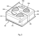
- the picture 3 offers a view of the isolated cartridge 130.
- the cartridge 130 is a removable element relative to the housing 100. The passenger of the vehicle can then easily change the cartridge, in particular when it is empty, the life of one cartridge being about 3 months for normal use.
- vacuum we mean whose fragrances are exhausted and no longer release volatile compounds.
- the cartridge is here provided with an insertion front 310 in said case, presenting itself in a manner similar to the front of a drawer.
- Said facade 310 is here provided with housings 312 ( figure 5 ) facilitating the insertion of said cartridge 130 into the housing 100.
- the cartridge 130 is also provided with a longitudinal guide rib 315 located along the three vertical faces which will be inserted into the housing 100.
- the housing also has guide grooves 160, illustrated on the figure 1 , on either side of the cartridge housing in the housing and above the lower turntable 125a.
- a slot 320 allows the axis to pass when the cartridge is inserted into the housing between the two turntables 125a and 125b illustrated in figure 1 and 2 .
- the movable axis 135 is located in the center of the cartridge in the bottom of the slot.
- the cartridge comprises a body 360 and a lid 350 whose shape is parallelepipedic and the base is substantially square.
- the body is compartmentalized to define said cavities, the bottom of said body includes the airflow inlets of said cavities, and the cover includes the airflow outlets of said cavities.
- the cartridge is preferably made of plastic material. Said openings may be covered with a mesh or a porous film to retain the substrate of said fragrances while allowing the flow of air to pass through.
- cavities occupied by a fragrance and empty cavities alternate.
- the alternation of empty cavities and cavities housing a fragrance makes it possible to pass from each of the cavities comprising a fragrance to a cavity not comprising any, without passing through a cavity comprising another fragrance.
- the various cavities of the cartridge and their respective openings form angular portions of a ring.
- five cavities are provided, three of which to house a fragrance 340a, 340c, 340e and two are intentionally left empty 340b, 340d.
- the angle swept by the openings of each angular portion is in this embodiment slightly less than 60 degrees.
- the openings 260a, 260b of the plates are also in the form of an angular portion, each plate here comprising a single opening 260a, 260b respectively.
- the passenger can therefore choose between three different fragrances according to his tastes: different atmospheres are possible during the trip, which can be particularly pleasant for long trips. These different fragrances can also be very useful for masking or filtering an undesirable smell of tobacco, for example.
- the passenger can also choose to leave the ventilation system running without being in the presence of a fragrance.
- the figure 4a to 4b illustrate a top view of the mechanism allowing the change of fragrances carried out by the assembly comprising the cartridge 130 and the selector 125a, 125b.
- the figure only shows the turntable 125b located on the cartridge 130. However, the bottom view would be shown the same way.
- the movable axis 135 as well as the slot 320 of the cartridge 130 are also visible in the figure.
- the figures 4a to 4e illustrate the passage of the opening 260b of the turntable 125b on each of the five positions.
- the figure 4a illustrates the first position of the turntable where the released fragrance comes from the cavity 340a of the picture 3 .
- the turntable will rotate counterclockwise through an angle of approximately 60 degrees. This position corresponds to a empty cavity of the cartridge corresponding to the cavity 340b of the picture 3 .
- the figure 4c illustrates the effect of an additional counterclockwise rotation of approximately 60 degrees relative to the second position to release the second fragrance housed in the cavity 340c.
- the figures 4d and 4e illustrate the opening of the turntable located respectively on the cavities 340d for the fourth position and 340e for the fifth position of the cartridge.
- the turntable will turn clockwise. Indeed, there is an area through which the turntable does not pass during use. This area is above slot 320, or between cavities 340a and 340e.
- the alternation of empty cavities and cavities housing a fragrance allows the passenger to adjust the intensity of the fragrance diffused by actuation of the selector back and forth.
- the speed of the turntable to go from a fragrance to a fragrance-free use is advantageously 0.5 seconds.
- the transition speed to pass from the first position to the fifth position, and vice versa is 2.5 seconds.
- the motor 140 is of the stepper motor-reduction type. This type of standard engine is chosen for reasons of cost and market availability. As illustrated on the figure 1 and 2 , the transmission shaft and pinion have an angular portion. This is because the rotation range of turntables is not 360°, but 240° as discussed above.
- a control system for the device may comprise a programming module and the associated electronics in order to allow the passenger to control the pulser and the motor of the electrical actuation mechanism.
- the passenger can control the fragrance dispenser from a steering wheel control.
- the control system allows the driver to turn on the fragrance dispenser, to choose the intensity of the fragrance diffused, to choose the flow rate of the diffused air flow and/or to choose the fragrance.
- the control system indicates when a fragrance from the cartridge is empty.
- control system allows the passenger to choose the fragrance he wishes to diffuse. Then, he can also adjust the flow rate of the air flow generated by the blower. The system of control also allows the passenger to adjust the intensity of the fragrance he wishes to diffuse.
- the control system may also allow the passenger to preprogram a diffusion sequence that he wishes by choosing a diffusion duration, a fragrance and its intensity.
- the intensity may also vary over time; it is therefore possible to start with a total diffusion which becomes partial over time.
- the control system also makes it possible to choose a broadcast frequency. For example, the passenger can choose to diffuse a certain fragrance for a chosen duration, and then diffuse nothing for another duration.
- the cartridge immobilization system 130 comprises a trigger 400, allowing in a first position, the maintenance of said cartridge in said housing, and in a second position, the introduction / extraction of said cartridge 130 relative to said housing 100 .
- the trigger 400 is in its first position.
- said trigger 400 can be actuated in translation in one direction, illustrated by an arrow marked 412 at the figure 6 , transverse, in particular orthogonal, to a direction of introduction/extraction of the cartridge, illustrated by an arrow marked 414 at the figure 6 (as well as the figure 1 ).
- Such an orientation makes it possible to have a simple and robust trigger.
- Said trigger 400 comprises, according to the invention, a bar 420 for blocking the cartridge 130 and comprises for example a tongue 422 for actuating the bar 420.
- Said tongue 422 here projects perpendicularly to the bar with which it may come of matter.
- the housing 100 comprises a front face 424, provided with an orifice 426 for inserting/extracting the cartridge 130.
- Said front face 424 is also provided with a notch 428 for the passage of the tongue 422, allowing the user to manipulate the latter from the outside, in a movement oriented along the direction 412.
- Said notch 428 may be formed in the outline of the orifice 426 for inserting/extracting the cartridge 130 or, as here, be independent.
- said front face 424 of the casing forms a facade for receiving the cartridge 130.
- Said tongue 422 may be configured to come face to face with two opposite longitudinal edges of said notch 428, with a slight play, so that said tongue 422 is guided along said longitudinal edges of the notch, thus facilitating guiding the strip 420 in its translational movement.
- Said strip 420 comprises, according to the invention, at least one stop 430, here two stops 430, for blocking the cartridge 130.
- said stops 430 are located at an outline of said strip 420, in particular along one of its edges 432, called lower, at two opposite longitudinal ends of said strip 420.
- said cartridge comprises at least one locking pin 434, here two locking pins 434, each intended to cooperate with one of said stops 430.
- said strip 420 is movable in translation along a face of the cartridge, in particular the upper face, namely the face of the cartridge at which said upper turntable 125b moves.
- Said blocking pins 434 are also located at the level of said upper face, at the level of vertices of the cartridge so as to be outside the space occupied by said upper turntable 125b, when the cartridge is in position.
- said blocking pins 434 are set back slightly from a rear face of the front 310 of the cartridge 130 so that said strip 420 is guided in its translation movement between said pins 434 and said front 310.
- Said blocking pin(s) 434 are advantageously provided with a cutaway, intended to cause actuation in translation of the strip 420 during the introduction of the cartridge 130.
- said trigger 400 may further comprise a return element, such as a spring 438, able to maintain the bar 420 in said first position in the absence of actuation of the trigger 400, that is to say, as long as the tab 422 is not moved by a user wishing to remove the cartridge 130.
- Said spring 438 bears on the housing 100, here on a side face of said housing, and on said bar 420, for example via a plate 440 provided with a guide pin 442 of the spring 438.
- Said plate 440 may come from said strip 420.
- Said guide pin 442 is advantageously oriented in the direction of translation 412 of the strip 420.
- said housing 100 may further comprise one or more studs 452 for guiding the bar 420, here from the upper face of said housing. Said bar 420 is located between said guide studs 452 and said front face of case 100.
- the immobilization system in accordance with the invention has been described in the context of a device for diffusing several fragrances, it can also be used with cartridges serving only a single fragrance. It can also be used with cartridges used for an application other than a distribution system.
Description
La présente invention concerne un système d'immobilisation d'une cartouche amovible dans un boîtier, en particulier destiné à être utilisé dans un dispositif de diffusion faisant partie d'un véhicule automobile.The present invention relates to a system for immobilizing a removable cartridge in a casing, in particular intended for use in a delivery device forming part of a motor vehicle.
Il est connu des dispositifs comprenant un boîtier et pourvus d'une cartouche amovible, et d'un bouton de verrouillage dudit élément amovible par rapport au boîtier.Devices comprising a housing and provided with a removable cartridge and a button for locking said removable element relative to the housing are known.
C'est le cas des dispositifs de diffusion que l'on trouve dans certains véhicules automobiles, comme décrit dans le document
L'invention a pour but d'améliorer la situation et propose à cette fin un ensemble comprenant un système d'immobilisation d'une cartouche amovible dans un boîtier et ladite cartouche amovible, suivant les caractéristiques de la revendication 1. Le système d'immobilisation de la cartouche selon l'invention comprend déclencheur, permettant dans une première position, le maintien de ladite cartouche dans ledit boîtier, et dans une seconde position, l'introduction/extraction de ladite cartouche par rapport audit boîtier, ledit déclencheur étant actionnable en translation selon une direction transversale à une direction d'introduction/extraction de la cartouche.The object of the invention is to improve the situation and to this end proposes an assembly comprising a system for immobilizing a removable cartridge in a housing and said removable cartridge, according to the characteristics of claim 1. The immobilization system of the cartridge according to the invention comprises trigger, allowing in a first position, the maintenance of said cartridge in said housing, and in a second position, the introduction/extraction of said cartridge relative to said housing, said trigger being operable in translation in a direction transverse to an insertion/extraction direction of the cartridge.
Une telle orientation du mouvement du déclencheur permet de disposer d'une solution d'immobilisation de la cartouche qui soit simple et robuste. De plus, selon l'invention, ledit déclencheur comprend une barrette de blocage de la cartouche, ladite barrette comprenant au moins une butée de blocage de la cartouche, la ou lesdites butées étant destinées à coopérer avec un ou des pions de blocage de ladite cartouche, le ou lesdits pions de blocage étant munis d'un pan coupé destiné à provoquer un actionnement en translation de la barrette lors de l'introduction de la cartouche.Such an orientation of the movement of the trigger makes it possible to have a solution for immobilizing the cartridge which is simple and robust. In addition, according to the invention, said trigger comprises a bar for blocking the cartridge, said bar comprising at least one abutment for blocking the cartridge, the said abutment(s) being intended to cooperate with one or more blocking pins of the said cartridge. , the said blocking pin(s) being provided with a cutaway intended to cause an actuation in translation of the bar during the introduction of the cartridge.
Selon des caractéristiques complémentaires de l'invention qui pourront être prises ensemble ou séparément :
- ledit déclencheur comprend une languette d'actionnement de la barrette,
- la ou lesdites butées sont situées au niveau d'un contour de ladite barrette,
- ledit déclencheur comprend un élément de rappel, apte à maintenir la barrette dans ladite première position en absence d'actionnement du déclencheur,
- ledit élément de rappel comprend un ressort,
- ledit ressort est configuré pour prendre appui sur ledit boîtier et sur ladite barrette,
- ladite barrette comprend une platine muni d'un doigt de guidage du ressort,
- ledit doigt de guidage est orienté selon la direction de translation de la barrette,
- ladite languette est configurée pour déboucher à travers une façade d'accueil dudit boîtier,
- la cartouche amovible est pourvue d'au moins une cavité,
- la cartouche comprend une pluralité d'ouvertures, en particulier en communication avec la ou lesdites dites cavités,
- lesdites cavités logent au moins un agent volatil,
- les agents volatils comprennent des billes odorantes,
- la cartouche comprend une façade d'introduction dans ledit boîtier,
- les différentes cavités de la cartouche forment des portions angulaires d'un anneau,
- ladite cartouche comprend un corps et un couvercle,
- ledit corps est compartimenté pour définir lesdites cavités,
- le ou lesdits pions de blocage sont situés au niveau d'une face, dite supérieure, de ladite cartouche,
- ladite barrette est mobile en translation le long de ladite face supérieure de la cartouche.
- said trigger comprises a tab for actuating the bar,
- the said abutment(s) are located at the level of a contour of the said strip,
- said trigger comprises a return element capable of holding the bar in said first position in the absence of actuation of the trigger,
- said return element comprises a spring,
- said spring is configured to bear on said housing and on said strip,
- said bar comprises a plate provided with a spring guide finger,
- said guide finger is oriented in the direction of translation of the bar,
- said tab is configured to emerge through a reception facade of said box,
- the removable cartridge is provided with at least one cavity,
- the cartridge comprises a plurality of openings, in particular in communication with the said cavity or cavities,
- said cavities house at least one volatile agent,
- volatile agents include scent beads,
- the cartridge comprises an insertion front in said casing,
- the various cavities of the cartridge form angular portions of a ring,
- said cartridge comprises a body and a lid,
- said body is compartmentalized to define said cavities,
- the said blocking pin(s) are located at a face, called the upper face, of the said cartridge,
- said bar is movable in translation along said upper face of the cartridge.
L'invention concerne aussi un dispositif de diffusion comprenant un ensemble tel que décrit plus haut.The invention also relates to a broadcasting device comprising an assembly as described above.
Selon différents modes de réalisation de l'invention qui pourront être pris ensemble ou séparément :
- ledit dispositif comprend un organe mobile, dit sélecteur, configuré pour laisser ouverte l'une au moins des ouvertures de la cartouche,
- ledit sélecteur comprend au moins une entrée et une sortie d'un flux d'air, ledit dispositif de diffusion étant configuré pour mettre en communication ladite entrée et ladite sortie, avec l'une au moins desdites cavités pour que cette dernière soit traversée par ledit flux d'air.
- said device comprises a movable member, called a selector, configured to leave open at least one of the openings of the cartridge,
- said selector comprises at least one inlet and one outlet for an air flow, said diffusion device being configured to place said inlet and said outlet in communication with at least one of said cavities so that the latter is crossed by said air flow.
L'invention sera mieux comprise à la lumière de la description suivante qui n'est donnée qu'à titre indicatif et qui n'a pas pour but de la limiter, accompagnée des dessins joints parmi lesquels :
- la
figure 1 illustre une vue globale en perspective d'un dispositif de diffusion selon l'invention, sans son système d'immobilisation, - la
figure 2 illustre le dispositif de lafigure 1 , sans son boîtier, - la
figure 3 illustre une vue en perspective de la cartouche du dispositif de lafigure 1 , - les
figures 4a à 4e illustrent de façon schématique, en vue de dessus, les différentes positions de l'organe mobile servant de sélecteur du dispositif de diffusion de lafigure 1 , - la
figure 5 illustre en perspective le dispositif de diffusion de lafigure 1 équipé de son système d'immobilisation, - la
figure 6 illustre en perspective la cartouche et un élément principal dudit système d'immobilisation - la
figure 7 illustre en perspective le dispositif de diffusion de lafigure 1 , selon une coupe transversale.
- the
figure 1 illustrates an overall perspective view of a diffusion device according to the invention, without its immobilization system, - the
figure 2 illustrates the device of thefigure 1 , without its case, - the
picture 3 illustrates a perspective view of the device cartridge of thefigure 1 , - the
figures 4a to 4e schematically illustrate, in top view, the different positions of the movable member serving as a selector of the device for broadcasting thefigure 1 , - the
figure 5 illustrates in perspective the device for broadcasting thefigure 1 equipped with its immobilization system, - the
figure 6 illustrates in perspective the cartridge and a main element of said immobilization system - the
figure 7 illustrates in perspective the device for broadcasting thefigure 1 , according to a cross-section.
Comme illustré sur les figures, l'invention concerne un système d'immobilisation d'une cartouche amovible dans un boîtier, en particulier pour un dispositif de diffusion permettant le traitement d'un flux d'air à l'aide d'agents volatils, notamment de fragrances.As illustrated in the figures, the invention relates to a system for immobilizing a removable cartridge in a housing, in particular for a diffusion device allowing the treatment of an air flow using volatile agents, especially fragrances.
Selon un mode de réalisation avantageux dudit dispositif, les agents volatils, notamment les fragrances, comprennent un substrat, notamment des billes, chargé en composé(s) volatil(s). Il pourra en particulier s'agir de billes odorantes.According to an advantageous embodiment of said device, the volatile agents, in particular the fragrances, comprise a substrate, in particular beads, loaded with volatile compound(s). It may in particular be fragrant balls.
A la
Le diffuseur comprend une cartouche 130 de fragrances et un sélecteur, ici logés dans ledit boîtier 100. Le sélecteur comprend, par exemple, un sélecteur d'entrée 125a, un sélecteur de sortie 125b et un axe mobile 135 les entraînant. Ledit diffuseur comprend en outre ici un mécanisme d'actionnement 150, permettant un entraînement dudit axe 135.The diffuser comprises a
Le boîtier 100 peut être fixé à différents emplacements du véhicule, de préférence sur la planche de bord ou dans la boîte à gants afin que ce dernier soit facilement accessible au passager. En effet, la cartouche est amovible par rapport audit boîtier et il est avantageux que le passager puisse facilement changer la cartouche.The
La sortie d'air du boîtier 110 est reliée, par exemple, à une grille par laquelle l'air traité ou parfumé sort. Cette grille peut être fixée à différents emplacements dans le véhicule. De préférence, elle est située sur la planche de bord ou près des systèmes de ventilation du pare-brise, la grille étant reliée à la sortie du boîtier par la tubulure déjà évoquée.The air outlet of the
Ici, le boîtier 100 comprend une base 180, par exemple parallélépipède rectangle. Dans la base sont logés un pulseur 115 situé au-dessus de l'entrée 105 du boîtier et au moins une partie du mécanisme d'actionnement 150. Ledit mécanisme d'actionnement pourra comprendre un moteur 140. Ce dernier est fixé sur le boîtier 100 au-dessus du pulseur 115, et se trouve en dehors du boîtier. Au-dessus de la base 180, et à côté du moteur 140, une seconde partie du boîtier 170 possède une forme sensiblement cubique pour y loger le sélecteur de fragrances et la cartouche 130. Ces parties du boîtier sont assemblées l'une à l'autre. L'étanchéité à l'air est assurée dans l'ensemble du boîtier. L'orifice d'entrée 105 est donc dans la base 180 du boîtier 100, sur la face inférieure et en dessous du pulseur 115. L'orifice de sortie 110 est sur la face supérieure de la deuxième partie 170, au-dessus du sélecteur de sortie 125b.Here, the
L'air pénètre dans le boîtier par l'orifice d'entrée 105, en étant aspiré par le pulseur 115. Ce pulseur génère le flux d'air qui va finalement sortir du boîtier par l'orifice de sortie 110 après avoir traversé la cartouche 130. Le flux d'air est illustré par la ligne 120 sur la
La cartouche 130 est avantageusement composée d'une pluralité de cavités dans lesquelles différentes fragrances peuvent être logées. Le sélecteur 125a, 125b est configuré de sorte que l'une ou plusieurs de ces cavités soient traversées par le flux d'air afin que celui-ci soit chargé des composés volatils de la ou des fragrances sélectionnées. Autrement dit, lorsque le flux d'air traverse la ou lesdites cavités sélectionnées, l'air vient en contact avec l'ensemble du substrat contenu dans chacune desdites cavités et ledit substrat libère le ou les composés qui vont parfumer et/ou traiter le flux d'air, et ensuite l'habitacle du véhicule automobile.The
Pour cela, le flux d'air 120 pénètre dans la cartouche 130 par une entrée du sélecteur d'entrée. Le flux d'air traverse alors la cartouche 130 de part en part en passant par l'une ou plusieurs des cavités de ladite cartouche qu'il quitte à travers une sortie dudit sélecteur de sortie 125b. En faisant traverser la ou les cavités sélectionnées par le flux d'air, on s'assure d'un chargement optimisé du flux d'air par la fragrance, celui-ci venant au contact de l'ensemble de la surface du substrat associé. Après être sortie de la cartouche, le flux d'air est ici guidé jusqu'à l'orifice de sortie 110 du boîtier.For this, the
De manière préférentielle, le pulseur 115 permet au dispositif d'être indépendant du système de ventilation, de climatisation ou de chauffage dont le véhicule est éventuellement équipé. Il peut dès lors être utilisé indépendamment de ces systèmes, ce qui le rend d'autant plus flexible à l'utilisation. Dans un autre mode de réalisation, il est relié au système de ventilation, de climatisation ou de chauffage du véhicule. L'orifice d'entrée 105 et de sortie 110 seraient dans ce mode de réalisation relié à un conduit dudit système.Preferably, the
La
Le mécanisme d'actionnement 150 comprend par exemple le moteur 140, un arbre 220, un pignon de transmission 230, permettant avantageusement une démultiplication, et un pignon droit 240. Le moteur 140 entraîne la cinématique des éléments situés en aval : l'arbre 220, directement relié à un actuateur du moteur, entraîne le pignon de transmission 230, qui entraîne le pignon droit 240. L'axe mobile 135 est directement fixé sur le pignon droit 240 et est dès lors également entraîné par ce dernier.The
Avantageusement, le sélecteur d'entrée 125a et le sélecteur de sortie 125b se présentent sous la forme de plateaux tournants, l'axe mobile 135 perçant les deux plateaux tournants en leur centre. La forme du trou perçant les plateaux tournants correspond à la forme d'une section de l'axe mobile, de préférence de forme carrée de telle sorte que lorsque l'axe mobile tourne, les plateaux tournants tournent également. Les plateaux tournants sont séparés par une distance correspondant à la hauteur de la cartouche 130 afin de permettre à la cartouche d'y être insérée. Lorsque la cartouche est insérée entre les deux plateaux, ces derniers sont avantageusement pressés contre la cartouche par des ressorts, non illustrés, afin d'assurer l'étanchéité à l'air.Advantageously, the
De préférence, l'entrée et la sortie du flux d'air sur les plateaux tournants situés respectivement en amont et en aval de la cartouche se présentent sous la forme d'ouvertures débouchantes 260b (l'ouverture 260a en amont de la cartouche n'est pas visible) dont la taille est comparable à celle d'une entrée, respectivement d'une sortie d'air, d'une cavité de la cartouche. Les ouvertures des deux plateaux tournants sont disposées en vis-à-vis de manière à assurer la continuité du flux d'air. D'autre part, les positions des ouvertures desdits plateaux tournants restent synchronisées pendant leur mouvement grâce à l'axe mobile 135 qui les relie.Preferably, the inlet and outlet of the air flow on the turntables located respectively upstream and downstream of the cartridge are in the form of through
La
La cartouche est ici munie d'une façade d'introduction 310 dans ledit boîtier, se présentant de manière similaire à la façade d'un tiroir. Ladite façade 310 est ici munie de logements 312 (
Une fente 320 permet le passage de l'axe lorsque la cartouche est insérée dans le boîtier entre les deux plateaux tournants 125a et 125b illustrés aux
La cartouche comprend un corps 360 et un couvercle 350 dont la forme est parallélépipédique et la base est sensiblement carrée. Le corps est compartimenté pour définir lesdites cavités, le fond dudit corps comprend les entrées du flux d'air desdites cavités, et le couvercle comprend les sorties du flux d'air desdites cavités. La cartouche est de préférence en matière plastique. Lesdites ouvertures pourront être revêtues d'un grillage ou d'un film poreux pour retenir le substrat desdites fragrances tout en laissant passer le flux d'air à travers.The cartridge comprises a
Avantageusement, des cavités occupées par une fragrance et des cavités vides alternent. L'alternance de cavités vides et de cavités logeant une fragrance permet de passer de chacune des cavités comprenant un fragrance à une cavité n'en comportant pas, sans passer par un cavité comprenant une autre fragrance.Advantageously, cavities occupied by a fragrance and empty cavities alternate. The alternation of empty cavities and cavities housing a fragrance makes it possible to pass from each of the cavities comprising a fragrance to a cavity not comprising any, without passing through a cavity comprising another fragrance.
Dans un mode de réalisation tel qu'illustré sur la
Le passager peut dès lors choisir entre trois fragrances différentes selon ses goûts : différentes ambiances sont envisageables pendant le voyage, ce qui peut être particulièrement agréable pour les longs voyages. Ces différentes fragrances peuvent également être très utiles pour masquer ou filtrer une odeur indésirable de tabac par exemple. Le passager peut également choisir de laisser le système de ventilation en marche sans pour autant être en présence d'une fragrance.The passenger can therefore choose between three different fragrances according to his tastes: different atmospheres are possible during the trip, which can be particularly pleasant for long trips. These different fragrances can also be very useful for masking or filtering an undesirable smell of tobacco, for example. The passenger can also choose to leave the ventilation system running without being in the presence of a fragrance.
Une telle distribution des cavités, sous la forme de portions angulaires en anneau, permet de facilement augmenter le nombre de cavités sans pour autant devoir modifier le mécanisme d'actionnement associé. Le seul changement à effectuer pour augmenter le nombre de fragrances disponibles au passager réside dans la taille des cavités de la cartouche et dans la taille des ouvertures des plateaux tournants qui leur correspondent.Such a distribution of the cavities, in the form of angular portions in a ring, makes it possible to easily increase the number of cavities without however having to modify the associated actuation mechanism. The only change to be made to increase the number of fragrances available to the passenger lies in the size of the cavities of the cartridge and in the size of the openings of the turntables which correspond to them.
Les
Dans le mode de réalisation décrit à la
Préférentiellement, pour passer à une position ultérieure, la plaque tournante va tourner dans le sens horaire. En effet, il y a une zone par laquelle la plaque tournante ne passe pas pendant son utilisation. Cette zone se trouve au-dessus de la fente 320, ou entre les cavités 340a et 340e.Preferably, to move to a later position, the turntable will turn clockwise. Indeed, there is an area through which the turntable does not pass during use. This area is above
L'alternance de cavités vides et de cavités logeant une fragrance permet au passager de régler l'intensité de la fragrance diffusée par un actionnement du sélecteur en va-et-vient. Dans le même but, il est également possible de placer l'ouverture du plateau tournant en une position intermédiaire entre la cavité vide et la cavité remplie. Lorsque l'ouverture recouvre en totalité l'ouverture de la cavité, alors la diffusion est totale, lorsque l'ouverture recouvre seulement une partie de l'ouverture de la cavité comportant l'agent volatil, alors la diffusion n'est que partielle.The alternation of empty cavities and cavities housing a fragrance allows the passenger to adjust the intensity of the fragrance diffused by actuation of the selector back and forth. For the same purpose, it is also possible to place the opening of the turntable in an intermediate position between the empty cavity and the filled cavity. When the opening completely covers the opening of the cavity, then the diffusion is total, when the opening covers only part of the opening of the cavity comprising the volatile agent, then the diffusion is only partial.
La vitesse du plateau tournant pour passer d'une fragrance à une utilisation sans fragrance est avantageusement de 0.5 seconde. Par suite, la vitesse de transition pour passer de la première position à la cinquième position, et vice-versa, est de 2.5 secondes.The speed of the turntable to go from a fragrance to a fragrance-free use is advantageously 0.5 seconds. As a result, the transition speed to pass from the first position to the fifth position, and vice versa, is 2.5 seconds.
Ce changement rapide entre différentes positions est rendu possible grâce au mécanisme d'actionnement 150 illustré sur les
Dans un mode de réalisation préféré, le moteur 140 est de type moto-réducteur pas à pas. Ce type de moteur standard est choisi pour des raisons de coût et de disponibilité sur le marché. Comme illustré sur les
C'est la combinaison de l'arbre 220, du pignon de transmission 230 et du pignon droit 240 qui permet une démultiplication du mouvement induit par le moto-réducteur 140 de telle sorte que le sélecteur passe d'une position à la suivante en 0.5 secondes et de la première position à la cinquième position en 2.5 secondes, et vice-versa. La combinaison de ces trois éléments forme un organe de démultiplication qui permet d'obtenir de telles performances avec un moteur standard.It is the combination of the
Un système de commande du dispositif pourra comprendre un module de programmation et l'électronique associée afin de permettre au passager de contrôler le pulseur et le moteur du mécanisme d'actionnement électrique. Préférentiellement, le passager peut contrôler le distributeur de fragrances à partir d'une commande au volant.A control system for the device may comprise a programming module and the associated electronics in order to allow the passenger to control the pulser and the motor of the electrical actuation mechanism. Preferably, the passenger can control the fragrance dispenser from a steering wheel control.
Le système de commande permet au conducteur de mettre le distributeur de fragrances sous tension, de choisir l'intensité de la fragrance diffusée, de choisir le débit du flux d'air diffusé et/ou de choisir la fragrance. Avantageusement, le système de commande indique lorsqu'une fragrance de la cartouche est vide.The control system allows the driver to turn on the fragrance dispenser, to choose the intensity of the fragrance diffused, to choose the flow rate of the diffused air flow and/or to choose the fragrance. Advantageously, the control system indicates when a fragrance from the cartridge is empty.
Dans un premier temps, le système de commande permet au passager de choisir la fragrance qu'il souhaite diffuser. Ensuite, il peut également régler le débit du flux d'air généré par le pulseur. Le système de commande permet également au passager de régler l'intensité de la fragrance qu'il souhaite diffuser.Initially, the control system allows the passenger to choose the fragrance he wishes to diffuse. Then, he can also adjust the flow rate of the air flow generated by the blower. The system of control also allows the passenger to adjust the intensity of the fragrance he wishes to diffuse.
Le système de commande pourra en outre permettre au passager de préprogrammer une séquence de diffusion qu'il souhaite en choisissant une durée de diffusion, une fragrance et son intensité. L'intensité pourra également varier au cours du temps ; il est dès lors possible de commencer par une diffusion totale qui devient partielle au cours du temps. Le système de commande permet également de choisir une fréquence de diffusion. Par exemple, le passager peut choisir de diffuser une certaine fragrance pendant une durée choisie, et puis ne rien diffuser pendant une autre durée.The control system may also allow the passenger to preprogram a diffusion sequence that he wishes by choosing a diffusion duration, a fragrance and its intensity. The intensity may also vary over time; it is therefore possible to start with a total diffusion which becomes partial over time. The control system also makes it possible to choose a broadcast frequency. For example, the passenger can choose to diffuse a certain fragrance for a chosen duration, and then diffuse nothing for another duration.
Comme illustré aux
Selon l'invention, ledit déclencheur 400 est actionnable en translation selon une direction, illustrée par une flèche repérée 412 à la
Ledit déclencheur 400 comprend, selon l'invention, une barrette 420 de blocage de la cartouche 130 et comprend par exemple une languette 422 d'actionnement de la barrette 420. Ladite languette 422 fait ici saillie perpendiculairement à la barette avec laquelle elle est éventuellement issue de matière.Said
Le boîtier 100 comprend une face frontale 424, munie d'un orifice 426 d'introduction/extraction de la cartouche 130. Ladite face frontale 424 est également munie d'une encoche 428 de passage de la languette 422, permettant à l'utilisateur de manipuler cette dernière depuis l'extérieur, selon un mouvement orienté suivant la direction 412. Ladite encoche 428 pourra être formée dans le contour de l'orifice 426 d'introduction/extraction de la cartouche 130 ou, comme ici, être indépendante. Avec un cadre 425 du dispositif, ladite face frontale 424 du boîtier forme une façade d'accueil de la cartouche 130.The
Ladite languette 422 pourra être configurée pour venir en vis-à-vis de de deux bords longitudinaux opposés de ladite encoche 428, avec un léger jeu, de sorte que ladite languette 422 est guidée le long desdits bord longitudinaux de l'encoche, facilitant ainsi le guidage de la barrette 420 dans son mouvement de translation.
Ladite barrette 420 comprend, selon l'invention, au moins une butée 430, ici deux butées 430, de blocage de la cartouche 130. Dans l'exemple, lesdites butées 430 sont situées au niveau d'un contour de ladite barrette 420, notamment le long de l'un de ses bords 432, dit inférieur, au niveau de deux extrémités longitudinales opposées de ladite barrette 420.Said
De son côté, ladite cartouche comprend au moins un pion de blocage 434, ici deux pions de blocage 434, destiné chacun à coopérer avec l'une desdites butées 430. Dans l'exemple, ladite barrette 420 est mobile en translation le long d'une face de la cartouche, notamment la face supérieure, à savoir la face de la cartouche au niveau de laquelle se déplace ledit plateau tournant supérieur 125b. Lesdits pions de blocage 434 sont également situés au niveau de ladite face supérieure, au niveau de sommets de la cartouche de façon à être en dehors de l'encombrement dudit plateau tournant supérieur 125b, lorsque la cartouche est en position.For its part, said cartridge comprises at least one
De façon préférentielle, lesdit pions de blocage 434 sont légèrement en retrait d'une face arrière de la façade 310 de la cartouche 130 de sorte que ladite barette 420 est guidée dans son mouvement de translation entre lesdits pions 434 et ladite façade 310.Preferably, said blocking pins 434 are set back slightly from a rear face of the
Le ou lesdits pions de blocage 434 sont avantageusement munis d'un pan coupé, destiné à provoquer un actionnement en translation de la barrette 420 lors de l'introduction de la cartouche 130.Said blocking pin(s) 434 are advantageously provided with a cutaway, intended to cause actuation in translation of the
Comme illustré à la
A la
Toujours à la
Bien que le système d'immobilisation conforme à l'invention ait été décrit dans le cadre d'un dispositif de diffusion de plusieurs fragrances, il pourra aussi être utilisé avec des cartouches ne servant qu'à une seule fragrance. Il pourra aussi être utilisé avec des cartouches servant à une autre application qu'un système de diffusion.Although the immobilization system in accordance with the invention has been described in the context of a device for diffusing several fragrances, it can also be used with cartridges serving only a single fragrance. It can also be used with cartridges used for an application other than a distribution system.
Claims (10)
- Assembly comprising a system for immobilizing a removable cartridge (130) in a housing (100) and said removable cartridge (130), said system comprising a trigger (400) which, in a first position, allows said cartridge (130) to be held in said housing (100) and, in a second position, allows said cartridge (130) to be inserted/extracted with respect to said housing, characterized in that said trigger (400) is actuable in translation in a direction transverse to a direction of insertion/extraction of the cartridge (130), said trigger (400) comprising a bar (420) for blocking the cartridge (130), said bar (420) comprising at least one stop (430) for blocking the cartridge (130), said stop(s) (430) being intended to cooperate with one or more blocking studs (434) of said cartridge (130), in which assembly said blocking stud(s) (434) is (are) provided with a bevel intended to cause the bar (420) to be actuated in translation when inserting the cartridge (130).
- Assembly according to Claim 1, in which said trigger (400) comprises a tab (422) for actuating the bar (420).
- Assembly according to Claim 2, in which said tab (422) is configured to emerge through a reception façade of said housing (100).
- Assembly according to Claim 1, in which said stop(s) (430) is (are) situated on a contour of said bar (420).
- Assembly according to any one of the preceding claims, in which said trigger (400) comprises a return element able to keep the bar (420) in said first position in the absence of actuation of the trigger.
- Assembly according to Claim 5, in which said return element comprises a spring (438), said spring being configured to bear on said housing (100) and on said bar (420) .
- Assembly according to Claim 6, in which said bar (420) comprises a plate (440) provided with a finger (442) for guiding the spring (438).
- Assembly according to any one of the preceding claims, in which said blocking stud(s) (434) is (are) situated on a face, termed upper face, of said cartridge (130) .
- Assembly according to Claim 8, in which said bar (420) is movable in translation along said upper face of the cartridge (130).
- Volatile agent diffusion device comprising the assembly according to any one of Claims 1 to 9.
Applications Claiming Priority (2)
| Application Number | Priority Date | Filing Date | Title |
|---|---|---|---|
| FR1550668A FR3032011B1 (en) | 2015-01-28 | 2015-01-28 | SYSTEM FOR IMMOBILIZATION OF A REMOVABLE CARTRIDGE IN A CASE |
| PCT/EP2016/051106 WO2016120137A1 (en) | 2015-01-28 | 2016-01-20 | System for immobilising a removable cartridge in a housing |
Publications (2)
| Publication Number | Publication Date |
|---|---|
| EP3265332A1 EP3265332A1 (en) | 2018-01-10 |
| EP3265332B1 true EP3265332B1 (en) | 2022-01-19 |
Family
ID=53200090
Family Applications (1)
| Application Number | Title | Priority Date | Filing Date |
|---|---|---|---|
| EP16701130.3A Active EP3265332B1 (en) | 2015-01-28 | 2016-01-20 | System for immobilising a removable cartridge in a housing |
Country Status (6)
| Country | Link |
|---|---|
| EP (1) | EP3265332B1 (en) |
| JP (1) | JP6567676B2 (en) |
| KR (1) | KR20170116060A (en) |
| CN (1) | CN107206869B (en) |
| FR (1) | FR3032011B1 (en) |
| WO (1) | WO2016120137A1 (en) |
Families Citing this family (3)
| Publication number | Priority date | Publication date | Assignee | Title |
|---|---|---|---|---|
| FR3063681A1 (en) * | 2017-03-08 | 2018-09-14 | Valeo Systemes Thermiques | DEVICE FOR IMMOBILIZATION OF A CARTRIDGE IN A CASE, HOUSING COMPRISING SAID DEVICE AND ASSEMBLY OF SAID HOUSING AND OF SAID CARTRIDGE |
| DE102020201256A1 (en) * | 2020-02-03 | 2021-08-05 | Mahle International Gmbh | Scenting device |
| CZ2020186A3 (en) | 2020-04-02 | 2021-10-13 | Ĺ KODA AUTO a.s. | Flavouring equipment for perfuming the interior of a vehicle |
Family Cites Families (7)
| Publication number | Priority date | Publication date | Assignee | Title |
|---|---|---|---|---|
| JP2693024B2 (en) * | 1990-08-01 | 1997-12-17 | キヤノン株式会社 | camera |
| JP3108171B2 (en) * | 1991-12-11 | 2000-11-13 | 株式会社リコー | Recording device and cartridge |
| IT1279566B1 (en) * | 1995-05-26 | 1997-12-16 | Fiat Auto Spa | AIR FILTRATION DEVICE FOR A VENTILATION SYSTEM, ESPECIALLY FOR A VEHICLE. |
| JP3416904B2 (en) * | 1997-09-19 | 2003-06-16 | 東芝テック株式会社 | Inkjet printer |
| FR2833887B1 (en) * | 2001-12-20 | 2004-02-27 | Valeo Climatisation | DEVICE FOR ODORIZING THE INTERIOR OF A MOTOR VEHICLE |
| JP5056163B2 (en) * | 2007-05-25 | 2012-10-24 | ブラザー工業株式会社 | Ink cartridge determination device and determination method |
| JP2010531765A (en) * | 2007-07-03 | 2010-09-30 | ベール ゲーエムベーハー ウント コー カーゲー | Fragrance device especially for automobiles |
-
2015
- 2015-01-28 FR FR1550668A patent/FR3032011B1/en active Active
-
2016
- 2016-01-20 WO PCT/EP2016/051106 patent/WO2016120137A1/en active Application Filing
- 2016-01-20 CN CN201680007708.7A patent/CN107206869B/en active Active
- 2016-01-20 JP JP2017539607A patent/JP6567676B2/en active Active
- 2016-01-20 EP EP16701130.3A patent/EP3265332B1/en active Active
- 2016-01-20 KR KR1020177023789A patent/KR20170116060A/en not_active Application Discontinuation
Also Published As
| Publication number | Publication date |
|---|---|
| KR20170116060A (en) | 2017-10-18 |
| FR3032011B1 (en) | 2017-08-04 |
| JP2018507021A (en) | 2018-03-15 |
| EP3265332A1 (en) | 2018-01-10 |
| CN107206869A (en) | 2017-09-26 |
| CN107206869B (en) | 2021-02-02 |
| WO2016120137A1 (en) | 2016-08-04 |
| FR3032011A1 (en) | 2016-07-29 |
| JP6567676B2 (en) | 2019-08-28 |
Similar Documents
| Publication | Publication Date | Title |
|---|---|---|
| EP3265332B1 (en) | System for immobilising a removable cartridge in a housing | |
| EP3002142B1 (en) | System for locking a removable cartridge in a housing | |
| FR2880279A1 (en) | MULTI-ODOR DIFFUSION DEVICE | |
| EP2011678B1 (en) | Volatile agent diffusion device equipped with a blower for an automobile vehicle | |
| FR2918318A1 (en) | VOLATILE AGENT DIFFUSION DEVICE WITH CARTRIDGE EXTRACTION MEANS | |
| EP3200836B1 (en) | Diffusion device with two rotatable plates | |
| WO2019038507A1 (en) | Scent diffuser and scent diffusion device incorporating such a diffuser | |
| FR2833531A1 (en) | Odorization device for automobile compartment comprises casing with inlet and outlet windows and aromatic agent cassette housed in rotating support | |
| FR2849817A1 (en) | MIRROR FOR A VEHICLE COMPRISING A MIRROR MOUNTED SWIVELING ON TWO PERPENDICULAR AXES | |
| FR2564394A1 (en) | PARFUME DEVICE, IN PARTICULAR FOR MOTOR VEHICLES | |
| WO2016050545A1 (en) | Diffusion device and removable cartridge for said device | |
| WO2018162840A1 (en) | Device for immobilizing a cartridge in a casing, casing comprising said device, and assembly of said casing and said cartridge | |
| FR3026305A1 (en) | DIFFUSION DEVICE AND CARTRIDGE FOR SAID DEVICE | |
| EP3162383A1 (en) | Device for diffusing at least one volatile agent | |
| EP3302646B1 (en) | Auto-injector with a delay device comprising an epicyclic gear train | |
| FR2833534A1 (en) | DEVICE FOR ODORING THE INTERIOR OF A MOTOR VEHICLE | |
| FR2848915A1 (en) | DEVICE FOR DELIVERING AT LEAST ONE PERFUME IN A COCKPIT OF A MOTOR VEHICLE. | |
| EP1541396A1 (en) | Air vent for a vehicle, in particular an automotive vehicle, comprising a perfume dispenser | |
| FR3056110B1 (en) | STORAGE CASE FOR PRODUCT DIFFUSER CARTRIDGE | |
| FR2791114A1 (en) | Device for controlling direction and flow of fluid for ventilating car interiors. comprises main pipe, connecting ring, and diffusion pipe mounted between them so that three components together form unbroken outer wall | |
| EP3746030A1 (en) | Device for dosing or counting objects | |
| FR2920348A1 (en) | Removable disinfection cartridge for heating and air conditioning unit of motor vehicle, has rapid attaching unit i.e. groove, for cooperating with groove provided in opening of case of unit for temporarily fixing cartridge with case | |
| EP3426215B1 (en) | Tearable tape roll dispenser | |
| FR2918317A1 (en) | Volatile agent e.g. fragrance, diffusing device for motor vehicle, has detachable cap covering treated air outlet and equipped with gap for distributing treated air stream along radial direction with respect to rotation axis | |
| EP1193644B1 (en) | Assembly for exchange of data representative of an authorised automotive vehicle user |
Legal Events
| Date | Code | Title | Description |
|---|---|---|---|
| STAA | Information on the status of an ep patent application or granted ep patent |
Free format text: STATUS: THE INTERNATIONAL PUBLICATION HAS BEEN MADE |
|
| PUAI | Public reference made under article 153(3) epc to a published international application that has entered the european phase |
Free format text: ORIGINAL CODE: 0009012 |
|
| STAA | Information on the status of an ep patent application or granted ep patent |
Free format text: STATUS: REQUEST FOR EXAMINATION WAS MADE |
|
| 17P | Request for examination filed |
Effective date: 20170818 |
|
| AK | Designated contracting states |
Kind code of ref document: A1 Designated state(s): AL AT BE BG CH CY CZ DE DK EE ES FI FR GB GR HR HU IE IS IT LI LT LU LV MC MK MT NL NO PL PT RO RS SE SI SK SM TR |
|
| AX | Request for extension of the european patent |
Extension state: BA ME |
|
| DAV | Request for validation of the european patent (deleted) | ||
| DAX | Request for extension of the european patent (deleted) | ||
| STAA | Information on the status of an ep patent application or granted ep patent |
Free format text: STATUS: EXAMINATION IS IN PROGRESS |
|
| 17Q | First examination report despatched |
Effective date: 20200723 |
|
| STAA | Information on the status of an ep patent application or granted ep patent |
Free format text: STATUS: EXAMINATION IS IN PROGRESS |
|
| GRAP | Despatch of communication of intention to grant a patent |
Free format text: ORIGINAL CODE: EPIDOSNIGR1 |
|
| STAA | Information on the status of an ep patent application or granted ep patent |
Free format text: STATUS: GRANT OF PATENT IS INTENDED |
|
| INTG | Intention to grant announced |
Effective date: 20210630 |
|
| GRAJ | Information related to disapproval of communication of intention to grant by the applicant or resumption of examination proceedings by the epo deleted |
Free format text: ORIGINAL CODE: EPIDOSDIGR1 |
|
| STAA | Information on the status of an ep patent application or granted ep patent |
Free format text: STATUS: EXAMINATION IS IN PROGRESS |
|
| GRAP | Despatch of communication of intention to grant a patent |
Free format text: ORIGINAL CODE: EPIDOSNIGR1 |
|
| STAA | Information on the status of an ep patent application or granted ep patent |
Free format text: STATUS: GRANT OF PATENT IS INTENDED |
|
| INTC | Intention to grant announced (deleted) | ||
| INTG | Intention to grant announced |
Effective date: 20210927 |
|
| GRAS | Grant fee paid |
Free format text: ORIGINAL CODE: EPIDOSNIGR3 |
|
| STAA | Information on the status of an ep patent application or granted ep patent |
Free format text: STATUS: GRANT OF PATENT IS INTENDED |
|
| GRAA | (expected) grant |
Free format text: ORIGINAL CODE: 0009210 |
|
| STAA | Information on the status of an ep patent application or granted ep patent |
Free format text: STATUS: THE PATENT HAS BEEN GRANTED |
|
| AK | Designated contracting states |
Kind code of ref document: B1 Designated state(s): AL AT BE BG CH CY CZ DE DK EE ES FI FR GB GR HR HU IE IS IT LI LT LU LV MC MK MT NL NO PL PT RO RS SE SI SK SM TR |
|
| REG | Reference to a national code |
Ref country code: GB Ref legal event code: FG4D Free format text: NOT ENGLISH |
|
| REG | Reference to a national code |
Ref country code: CH Ref legal event code: EP |
|
| REG | Reference to a national code |
Ref country code: AT Ref legal event code: REF Ref document number: 1463600 Country of ref document: AT Kind code of ref document: T Effective date: 20220215 |
|
| REG | Reference to a national code |
Ref country code: IE Ref legal event code: FG4D Free format text: LANGUAGE OF EP DOCUMENT: FRENCH |
|
| REG | Reference to a national code |
Ref country code: DE Ref legal event code: R096 Ref document number: 602016068449 Country of ref document: DE |
|
| REG | Reference to a national code |
Ref country code: LT Ref legal event code: MG9D |
|
| REG | Reference to a national code |
Ref country code: NL Ref legal event code: MP Effective date: 20220119 |
|
| REG | Reference to a national code |
Ref country code: AT Ref legal event code: MK05 Ref document number: 1463600 Country of ref document: AT Kind code of ref document: T Effective date: 20220119 |
|
| PG25 | Lapsed in a contracting state [announced via postgrant information from national office to epo] |
Ref country code: NL Free format text: LAPSE BECAUSE OF FAILURE TO SUBMIT A TRANSLATION OF THE DESCRIPTION OR TO PAY THE FEE WITHIN THE PRESCRIBED TIME-LIMIT Effective date: 20220119 |
|
| PG25 | Lapsed in a contracting state [announced via postgrant information from national office to epo] |
Ref country code: SE Free format text: LAPSE BECAUSE OF FAILURE TO SUBMIT A TRANSLATION OF THE DESCRIPTION OR TO PAY THE FEE WITHIN THE PRESCRIBED TIME-LIMIT Effective date: 20220119 Ref country code: RS Free format text: LAPSE BECAUSE OF FAILURE TO SUBMIT A TRANSLATION OF THE DESCRIPTION OR TO PAY THE FEE WITHIN THE PRESCRIBED TIME-LIMIT Effective date: 20220119 Ref country code: PT Free format text: LAPSE BECAUSE OF FAILURE TO SUBMIT A TRANSLATION OF THE DESCRIPTION OR TO PAY THE FEE WITHIN THE PRESCRIBED TIME-LIMIT Effective date: 20220519 Ref country code: NO Free format text: LAPSE BECAUSE OF FAILURE TO SUBMIT A TRANSLATION OF THE DESCRIPTION OR TO PAY THE FEE WITHIN THE PRESCRIBED TIME-LIMIT Effective date: 20220419 Ref country code: LT Free format text: LAPSE BECAUSE OF FAILURE TO SUBMIT A TRANSLATION OF THE DESCRIPTION OR TO PAY THE FEE WITHIN THE PRESCRIBED TIME-LIMIT Effective date: 20220119 Ref country code: HR Free format text: LAPSE BECAUSE OF FAILURE TO SUBMIT A TRANSLATION OF THE DESCRIPTION OR TO PAY THE FEE WITHIN THE PRESCRIBED TIME-LIMIT Effective date: 20220119 Ref country code: ES Free format text: LAPSE BECAUSE OF FAILURE TO SUBMIT A TRANSLATION OF THE DESCRIPTION OR TO PAY THE FEE WITHIN THE PRESCRIBED TIME-LIMIT Effective date: 20220119 Ref country code: BG Free format text: LAPSE BECAUSE OF FAILURE TO SUBMIT A TRANSLATION OF THE DESCRIPTION OR TO PAY THE FEE WITHIN THE PRESCRIBED TIME-LIMIT Effective date: 20220419 |
|
| PG25 | Lapsed in a contracting state [announced via postgrant information from national office to epo] |
Ref country code: PL Free format text: LAPSE BECAUSE OF FAILURE TO SUBMIT A TRANSLATION OF THE DESCRIPTION OR TO PAY THE FEE WITHIN THE PRESCRIBED TIME-LIMIT Effective date: 20220119 Ref country code: LV Free format text: LAPSE BECAUSE OF FAILURE TO SUBMIT A TRANSLATION OF THE DESCRIPTION OR TO PAY THE FEE WITHIN THE PRESCRIBED TIME-LIMIT Effective date: 20220119 Ref country code: GR Free format text: LAPSE BECAUSE OF FAILURE TO SUBMIT A TRANSLATION OF THE DESCRIPTION OR TO PAY THE FEE WITHIN THE PRESCRIBED TIME-LIMIT Effective date: 20220420 Ref country code: FI Free format text: LAPSE BECAUSE OF FAILURE TO SUBMIT A TRANSLATION OF THE DESCRIPTION OR TO PAY THE FEE WITHIN THE PRESCRIBED TIME-LIMIT Effective date: 20220119 Ref country code: AT Free format text: LAPSE BECAUSE OF FAILURE TO SUBMIT A TRANSLATION OF THE DESCRIPTION OR TO PAY THE FEE WITHIN THE PRESCRIBED TIME-LIMIT Effective date: 20220119 |
|
| REG | Reference to a national code |
Ref country code: CH Ref legal event code: PL |
|
| PG25 | Lapsed in a contracting state [announced via postgrant information from national office to epo] |
Ref country code: IS Free format text: LAPSE BECAUSE OF FAILURE TO SUBMIT A TRANSLATION OF THE DESCRIPTION OR TO PAY THE FEE WITHIN THE PRESCRIBED TIME-LIMIT Effective date: 20220519 |
|
| REG | Reference to a national code |
Ref country code: BE Ref legal event code: MM Effective date: 20220131 |
|
| REG | Reference to a national code |
Ref country code: DE Ref legal event code: R097 Ref document number: 602016068449 Country of ref document: DE |
|
| PG25 | Lapsed in a contracting state [announced via postgrant information from national office to epo] |
Ref country code: SM Free format text: LAPSE BECAUSE OF FAILURE TO SUBMIT A TRANSLATION OF THE DESCRIPTION OR TO PAY THE FEE WITHIN THE PRESCRIBED TIME-LIMIT Effective date: 20220119 Ref country code: SK Free format text: LAPSE BECAUSE OF FAILURE TO SUBMIT A TRANSLATION OF THE DESCRIPTION OR TO PAY THE FEE WITHIN THE PRESCRIBED TIME-LIMIT Effective date: 20220119 Ref country code: RO Free format text: LAPSE BECAUSE OF FAILURE TO SUBMIT A TRANSLATION OF THE DESCRIPTION OR TO PAY THE FEE WITHIN THE PRESCRIBED TIME-LIMIT Effective date: 20220119 Ref country code: MC Free format text: LAPSE BECAUSE OF FAILURE TO SUBMIT A TRANSLATION OF THE DESCRIPTION OR TO PAY THE FEE WITHIN THE PRESCRIBED TIME-LIMIT Effective date: 20220119 Ref country code: LU Free format text: LAPSE BECAUSE OF NON-PAYMENT OF DUE FEES Effective date: 20220120 Ref country code: EE Free format text: LAPSE BECAUSE OF FAILURE TO SUBMIT A TRANSLATION OF THE DESCRIPTION OR TO PAY THE FEE WITHIN THE PRESCRIBED TIME-LIMIT Effective date: 20220119 Ref country code: DK Free format text: LAPSE BECAUSE OF FAILURE TO SUBMIT A TRANSLATION OF THE DESCRIPTION OR TO PAY THE FEE WITHIN THE PRESCRIBED TIME-LIMIT Effective date: 20220119 Ref country code: CZ Free format text: LAPSE BECAUSE OF FAILURE TO SUBMIT A TRANSLATION OF THE DESCRIPTION OR TO PAY THE FEE WITHIN THE PRESCRIBED TIME-LIMIT Effective date: 20220119 |
|
| PLBE | No opposition filed within time limit |
Free format text: ORIGINAL CODE: 0009261 |
|
| STAA | Information on the status of an ep patent application or granted ep patent |
Free format text: STATUS: NO OPPOSITION FILED WITHIN TIME LIMIT |
|
| PG25 | Lapsed in a contracting state [announced via postgrant information from national office to epo] |
Ref country code: BE Free format text: LAPSE BECAUSE OF NON-PAYMENT OF DUE FEES Effective date: 20220131 Ref country code: AL Free format text: LAPSE BECAUSE OF FAILURE TO SUBMIT A TRANSLATION OF THE DESCRIPTION OR TO PAY THE FEE WITHIN THE PRESCRIBED TIME-LIMIT Effective date: 20220119 |
|
| 26N | No opposition filed |
Effective date: 20221020 |
|
| GBPC | Gb: european patent ceased through non-payment of renewal fee |
Effective date: 20220419 |
|
| PG25 | Lapsed in a contracting state [announced via postgrant information from national office to epo] |
Ref country code: LI Free format text: LAPSE BECAUSE OF NON-PAYMENT OF DUE FEES Effective date: 20220131 Ref country code: CH Free format text: LAPSE BECAUSE OF NON-PAYMENT OF DUE FEES Effective date: 20220131 |
|
| PG25 | Lapsed in a contracting state [announced via postgrant information from national office to epo] |
Ref country code: IE Free format text: LAPSE BECAUSE OF NON-PAYMENT OF DUE FEES Effective date: 20220120 Ref country code: GB Free format text: LAPSE BECAUSE OF NON-PAYMENT OF DUE FEES Effective date: 20220419 |
|
| PG25 | Lapsed in a contracting state [announced via postgrant information from national office to epo] |
Ref country code: SI Free format text: LAPSE BECAUSE OF FAILURE TO SUBMIT A TRANSLATION OF THE DESCRIPTION OR TO PAY THE FEE WITHIN THE PRESCRIBED TIME-LIMIT Effective date: 20220119 |
|
| PGFP | Annual fee paid to national office [announced via postgrant information from national office to epo] |
Ref country code: FR Payment date: 20230125 Year of fee payment: 8 |
|
| PGFP | Annual fee paid to national office [announced via postgrant information from national office to epo] |
Ref country code: DE Payment date: 20230112 Year of fee payment: 8 |
|
| P01 | Opt-out of the competence of the unified patent court (upc) registered |
Effective date: 20230528 |
|
| PG25 | Lapsed in a contracting state [announced via postgrant information from national office to epo] |
Ref country code: IT Free format text: LAPSE BECAUSE OF FAILURE TO SUBMIT A TRANSLATION OF THE DESCRIPTION OR TO PAY THE FEE WITHIN THE PRESCRIBED TIME-LIMIT Effective date: 20220119 |
|
| PG25 | Lapsed in a contracting state [announced via postgrant information from national office to epo] |
Ref country code: HU Free format text: LAPSE BECAUSE OF FAILURE TO SUBMIT A TRANSLATION OF THE DESCRIPTION OR TO PAY THE FEE WITHIN THE PRESCRIBED TIME-LIMIT; INVALID AB INITIO Effective date: 20160120 |