EP3263883A1 - Intake manifold - Google Patents
Intake manifold Download PDFInfo
- Publication number
- EP3263883A1 EP3263883A1 EP17179086.8A EP17179086A EP3263883A1 EP 3263883 A1 EP3263883 A1 EP 3263883A1 EP 17179086 A EP17179086 A EP 17179086A EP 3263883 A1 EP3263883 A1 EP 3263883A1
- Authority
- EP
- European Patent Office
- Prior art keywords
- introducing port
- branch
- intake
- port
- branch ports
- Prior art date
- Legal status (The legal status is an assumption and is not a legal conclusion. Google has not performed a legal analysis and makes no representation as to the accuracy of the status listed.)
- Withdrawn
Links
- 230000007423 decrease Effects 0.000 claims abstract description 7
- 238000005192 partition Methods 0.000 description 8
- 238000005452 bending Methods 0.000 description 2
- 238000002485 combustion reaction Methods 0.000 description 2
- 230000002093 peripheral effect Effects 0.000 description 2
- 239000011347 resin Substances 0.000 description 2
- 229920005989 resin Polymers 0.000 description 2
- 238000000926 separation method Methods 0.000 description 2
- 230000000694 effects Effects 0.000 description 1
- 239000000463 material Substances 0.000 description 1
- 239000007769 metal material Substances 0.000 description 1
- 238000003466 welding Methods 0.000 description 1
Images


Classifications
-
- F—MECHANICAL ENGINEERING; LIGHTING; HEATING; WEAPONS; BLASTING
- F02—COMBUSTION ENGINES; HOT-GAS OR COMBUSTION-PRODUCT ENGINE PLANTS
- F02M—SUPPLYING COMBUSTION ENGINES IN GENERAL WITH COMBUSTIBLE MIXTURES OR CONSTITUENTS THEREOF
- F02M35/00—Combustion-air cleaners, air intakes, intake silencers, or induction systems specially adapted for, or arranged on, internal-combustion engines
- F02M35/10—Air intakes; Induction systems
- F02M35/104—Intake manifolds
-
- F—MECHANICAL ENGINEERING; LIGHTING; HEATING; WEAPONS; BLASTING
- F02—COMBUSTION ENGINES; HOT-GAS OR COMBUSTION-PRODUCT ENGINE PLANTS
- F02M—SUPPLYING COMBUSTION ENGINES IN GENERAL WITH COMBUSTIBLE MIXTURES OR CONSTITUENTS THEREOF
- F02M35/00—Combustion-air cleaners, air intakes, intake silencers, or induction systems specially adapted for, or arranged on, internal-combustion engines
- F02M35/10—Air intakes; Induction systems
- F02M35/10006—Air intakes; Induction systems characterised by the position of elements of the air intake system in direction of the air intake flow, i.e. between ambient air inlet and supply to the combustion chamber
- F02M35/10026—Plenum chambers
- F02M35/10032—Plenum chambers specially shaped or arranged connecting duct between carburettor or air inlet duct and the plenum chamber; specially positioned carburettors or throttle bodies with respect to the plenum chamber
-
- F—MECHANICAL ENGINEERING; LIGHTING; HEATING; WEAPONS; BLASTING
- F02—COMBUSTION ENGINES; HOT-GAS OR COMBUSTION-PRODUCT ENGINE PLANTS
- F02M—SUPPLYING COMBUSTION ENGINES IN GENERAL WITH COMBUSTIBLE MIXTURES OR CONSTITUENTS THEREOF
- F02M35/00—Combustion-air cleaners, air intakes, intake silencers, or induction systems specially adapted for, or arranged on, internal-combustion engines
- F02M35/10—Air intakes; Induction systems
- F02M35/10006—Air intakes; Induction systems characterised by the position of elements of the air intake system in direction of the air intake flow, i.e. between ambient air inlet and supply to the combustion chamber
- F02M35/10026—Plenum chambers
- F02M35/10052—Plenum chambers special shapes or arrangements of plenum chambers; Constructional details
-
- F—MECHANICAL ENGINEERING; LIGHTING; HEATING; WEAPONS; BLASTING
- F02—COMBUSTION ENGINES; HOT-GAS OR COMBUSTION-PRODUCT ENGINE PLANTS
- F02M—SUPPLYING COMBUSTION ENGINES IN GENERAL WITH COMBUSTIBLE MIXTURES OR CONSTITUENTS THEREOF
- F02M35/00—Combustion-air cleaners, air intakes, intake silencers, or induction systems specially adapted for, or arranged on, internal-combustion engines
- F02M35/10—Air intakes; Induction systems
- F02M35/10242—Devices or means connected to or integrated into air intakes; Air intakes combined with other engine or vehicle parts
- F02M35/10262—Flow guides, obstructions, deflectors or the like
-
- F—MECHANICAL ENGINEERING; LIGHTING; HEATING; WEAPONS; BLASTING
- F02—COMBUSTION ENGINES; HOT-GAS OR COMBUSTION-PRODUCT ENGINE PLANTS
- F02M—SUPPLYING COMBUSTION ENGINES IN GENERAL WITH COMBUSTIBLE MIXTURES OR CONSTITUENTS THEREOF
- F02M35/00—Combustion-air cleaners, air intakes, intake silencers, or induction systems specially adapted for, or arranged on, internal-combustion engines
- F02M35/10—Air intakes; Induction systems
- F02M35/104—Intake manifolds
- F02M35/1045—Intake manifolds characterised by the charge distribution between the cylinders/combustion chambers or its homogenisation
-
- Y—GENERAL TAGGING OF NEW TECHNOLOGICAL DEVELOPMENTS; GENERAL TAGGING OF CROSS-SECTIONAL TECHNOLOGIES SPANNING OVER SEVERAL SECTIONS OF THE IPC; TECHNICAL SUBJECTS COVERED BY FORMER USPC CROSS-REFERENCE ART COLLECTIONS [XRACs] AND DIGESTS
- Y02—TECHNOLOGIES OR APPLICATIONS FOR MITIGATION OR ADAPTATION AGAINST CLIMATE CHANGE
- Y02T—CLIMATE CHANGE MITIGATION TECHNOLOGIES RELATED TO TRANSPORTATION
- Y02T10/00—Road transport of goods or passengers
- Y02T10/10—Internal combustion engine [ICE] based vehicles
- Y02T10/12—Improving ICE efficiencies
Definitions
- This disclosure relates to an intake manifold for distributing intake air to each cylinder of an internal combustion engine.
- an intake manifold described in JP 2012-97567A (Reference 1) is known.
- the intake manifold includes a surge tank to which intake air is supplied from an inlet to which a throttle valve is connected, and a plurality of outlet pipes (intake passages) which extend from a bottom portion of the surge tank toward an engine side, pass through an upward curved portion, and rise to face the surge tank.
- An intake guide surface which receives the intake air from an opening and closing side of the throttle valve to guide the intake air to an outside inner wall side that is a side opposite to the outlet pipe side, is formed on an inside inner wall that is an outlet pipe side of an inlet region. Therefore, it is said that the intake air flowing from the throttle valve flows smoothly into the outlet pipes and the intake efficiency improves.
- An intake manifold includes a surge tank portion to which intake air is supplied from an introducing port and which distributes the intake air to each intake passage from a plurality of branch ports juxtaposed in one direction.
- each of the branch ports opens so that a center thereof is positioned apart from a center line of the introducing port extending along an opening direction of the introducing port by a predetermined distance in a direction perpendicular thereto when viewed in a juxtaposed direction of the branch ports.
- One inner wall surface which is positioned in a direction opposite to a direction in which the center of the branch port is apart from the center line of the introducing port, has an inclined portion extending between and connecting the introducing port and all the plurality of branch ports.
- a protruding portion In the inclined portion, a protruding portion, whose top portion extends from the introducing port toward the branch port and is positioned within a range of the introducing port in the juxtaposed direction of the branch ports, and whose protruding length gradually decreases in directions opposite to each other from the top portion in the juxtaposed direction of the branch ports, is protruded.
- the inclined portion is inclined from the introducing port toward each branch port so that the intake air is supplied to each branch port in a state where the flow of the intake air flowing from the introducing port is guided. Therefore, it is possible to improve the intake efficiency.
- the protruding portion protruding to the inclined portion extends from the introducing port toward the branch port and the top portion is formed within the range of the introducing port in the juxtaposed direction of the branch ports. Therefore, it is possible to improve distribution properties of the intake air flowing in from the introducing port to the plurality of branch ports (intake passages).
- the branch ports open along a direction in which the inclined portion is inclined.
- the inclined portion can guide the flow of the intake air to the branch port without bending the flow thereof.
- the top portion extends toward a portion between adjacent two branch ports.
- an intake manifold 1 provided in an in-line three-cylinder engine (not illustrated) for a vehicle has a surge tank portion 2 and a plurality (three) of intake passages 3 branched from an outlet side of the surge tank portion 2.
- the intake manifold 1 is a so-called surge tank integrated-type intake manifold integrally including the surge tank portion 2 and the plurality of intake passages 3 by, for example, three resin pieces joined by vibration welding or the like.
- a juxtaposed direction of the plurality of intake passages 3 is referred to as an X direction.
- An introducing port 11 is formed on an inlet side in the surge tank portion 2.
- the introducing port 11 forms a substantially cylindrical inner wall surface 12 extending along a center line O1 in one direction (direction orthogonal to a paper surface in Fig. 1 C) orthogonal to the X direction and a substantially annular flange portion 14 protruding outward from an outer peripheral portion of an opening 13 of the introducing port 11.
- the flange portion 14 is provided for connecting to a throttle body (not illustrated) which holds a throttle valve or the like.
- the flange portion 16 is provided for connecting to a cylinder head (not illustrated).
- a plurality of branch ports 21 which are inlets of the plurality of intake passages 3 are juxtaposed on an outlet side thereof in the X direction.
- Each branch port 21 opens so as to be positioned apart from the center line O1 in which a center P thereof extends in an opening direction of the introducing port 11 by a predetermined distance LN in a direction orthogonal thereto when viewed in the X direction (direction orthogonal to a paper surface in Fig. 2C ).
- the plurality of intake passages 3 are formed so as to be in close contact with each other in the vicinity of the branch port 21 in the X direction.
- the surge tank portion 2 has an inner wall surface 23 which forms an inner space 22 that is a passage cross-sectional area larger than a passage cross-sectional area of the introducing port 11. That is, the inner wall surface 23 extends to both sides in the X direction with the introducing port 11 interposed therebetween and, for example, an opening width in the X direction is set to be greater than a dimension obtained by combining the plurality of intake passages 3 in the vicinity of the branch ports 21.
- a planar inclined portion 24 connecting between the introducing port 11 and all the plurality of branch ports 21 is formed on one inner wall surface 23a positioned in a direction opposite to a direction in which the center P of the branch port 21 is apart from the center line O1 of the introducing port 11 in the inner wall surface 23.
- the inclined portion 24 is inclined at a predetermined angle with respect to the center line O1 such that the center line O1 of the introducing port 11 intersects.
- a protruding portion 25 protrudes from the inclined portion 24 in a direction orthogonal thereto.
- a cross-sectional shape of the protruding portion 25 has a substantially triangular shape in which a protruding length gradually decreases from a top portion 25a toward the opposite X direction (rightward and leftward direction in Fig. 2B ). That is, in the cross-sectional shape of the protruding portion 25, the right side of the top portion 25a in the drawing is inclined in a substantially straight line at a predetermined angle and the left side of the top portion 25a in the drawing is curved in a substantially upward parabolic shape.
- the top portion 25a is positioned within a range of an opening of the introducing port 11 in the X direction.
- the top portion 25a coincides with a position on one side of a partition wall 17 (partition wall 17 on the left side in Fig. 2B ) that partitions the intake passages 3 adjacent to each other in the vicinity of the branch port 21 in the X direction. That is, the top portion 25a extends toward between (the partition wall 17) adjacent two branch ports 21.
- the protruding portion 25 extends from the introducing port 11 toward the branch port 21 in a direction orthogonal to the X direction, and the top portion 25a thereof extends toward the partition wall 17 which is described above substantially parallel to the inclined portion 24.
- a protruding length L of the protruding portion 25 gradually decreases from the top portion 25a toward the opposite direction in the X direction. More specifically, as illustrated in Fig. 3A , at the position of the top portion 25a, the protruding length L of the protruding portion 25 is the maximum protruding length L1.
- the intake passage 3 connected to the surge tank portion 2 along the inclined portion 24 is bent in the clockwise direction in Figs. 3A to 3C so as to be folded back toward the introducing port 11 side and passes through the introducing port 11 on the right side in Figs. 3A to 3C .
- the opening 15 (flange portion 16) thereof is disposed on the cylinder head side.
- the intake manifold 1 having such a configuration guides and distributes the intake air flowing into the surge tank portion 2 with the inclined portion 24 and the protruding portion 25 and supplies the intake air to a combustion chamber (not illustrated) of an engine provided at an end of each intake passage 3.
- the embodiment may be modified as follows.
- the branch port may be opened so that the inclined portion 24 is inclined along the direction thereof. That is, it may be a branch port whose center line extends in parallel to the inclined direction of the inclined portion 24 along the top portion 25a.
- the inclined portion 24 can guide the flow of the intake air to the branch port without bending and it is possible to suppress a decrease in the intake efficiency.
- the right side of the top portion 25a illustrated in Fig. 2B may not be inclined in a substantially straight line at a predetermined angle and the left side of the top portion 25a illustrated in Fig. 2B may not be curved in a substantially upward parabolic shape. That is, the cross-sectional shape of the protruding portion 25 may be a bow shape (circular arc, upward parabola, or the like) having a top portion, or a triangular shape. Alternatively, a pair of right and left downward parabolas may be combined so as to have a top portion.
- the protruding portion 25 may be formed only within the range of the opening of the introducing port 11.
- the top portion 25a of the protruding portion 25 may not coincide with the position of the partition wall 17 in the X direction.
- the intake manifold 1 may be a metal material instead of a resin material.
- the number of cylinders of the engine is arbitrary as long as it has a plurality of cylinders and the intake manifold 1 may have a number of the intake passages matching the number of cylinders.
Landscapes
- Engineering & Computer Science (AREA)
- Chemical & Material Sciences (AREA)
- Combustion & Propulsion (AREA)
- Mechanical Engineering (AREA)
- General Engineering & Computer Science (AREA)
- Physics & Mathematics (AREA)
- Geometry (AREA)
- Characterised By The Charging Evacuation (AREA)
Abstract
Description
- This disclosure relates to an intake manifold for distributing intake air to each cylinder of an internal combustion engine.
- In the related art, for example, an intake manifold described in
JP 2012-97567A - However, such an intake manifold does not take into consideration of distribution properties of the intake air to the plurality of outlet pipes.
- Thus, a need exists for an intake manifold that can improve distribution properties while improving intake efficiency.
- An intake manifold according to an aspect of this disclosure includes a surge tank portion to which intake air is supplied from an introducing port and which distributes the intake air to each intake passage from a plurality of branch ports juxtaposed in one direction. In the surge tank portion, each of the branch ports opens so that a center thereof is positioned apart from a center line of the introducing port extending along an opening direction of the introducing port by a predetermined distance in a direction perpendicular thereto when viewed in a juxtaposed direction of the branch ports. One inner wall surface, which is positioned in a direction opposite to a direction in which the center of the branch port is apart from the center line of the introducing port, has an inclined portion extending between and connecting the introducing port and all the plurality of branch ports. In the inclined portion, a protruding portion, whose top portion extends from the introducing port toward the branch port and is positioned within a range of the introducing port in the juxtaposed direction of the branch ports, and whose protruding length gradually decreases in directions opposite to each other from the top portion in the juxtaposed direction of the branch ports, is protruded.
- According to this configuration, the inclined portion is inclined from the introducing port toward each branch port so that the intake air is supplied to each branch port in a state where the flow of the intake air flowing from the introducing port is guided. Therefore, it is possible to improve the intake efficiency. In addition, the protruding portion protruding to the inclined portion extends from the introducing port toward the branch port and the top portion is formed within the range of the introducing port in the juxtaposed direction of the branch ports. Therefore, it is possible to improve distribution properties of the intake air flowing in from the introducing port to the plurality of branch ports (intake passages).
- In the intake manifold, it is preferable that the branch ports open along a direction in which the inclined portion is inclined.
- According to this configuration, the inclined portion can guide the flow of the intake air to the branch port without bending the flow thereof.
- In the intake manifold, it is preferable that the top portion extends toward a portion between adjacent two branch ports.
- According to this configuration, it is possible to prevent the intake air flowing in from the introducing port and flowing to the branch port from colliding with a portion between adjacent two branch ports.
- According to the aspect of this disclosure, it is possible to improve the distribution properties while improving the intake efficiency.
- The foregoing and additional features and characteristics of this disclosure will become more apparent from the following detailed description considered with the reference to the accompanying drawings, wherein:
-
Figs. 1A to 1D are respectively a perspective view, a front view, a plan view, and a side view illustrating a structure of an intake manifold of an embodiment; -
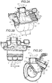
Figs. 2A and 2B are respectively sectional views that are taken alongline 2A-2A ofFig. 1D andline 2B-2B ofFig. 1C , andFig. 2C is a sectional view that is taken alongline 2C-2C ofFig. 2B ; and -
Figs. 3A to 3C are respectively sectional views that are taken alongline 3A-3A, 3B-3B, and 3C-3C ofFig. 1B . - Hereinafter, an embodiment of an intake manifold will be described with reference to the drawings.
- As illustrated in
Figs. 1A to 1D , anintake manifold 1 provided in an in-line three-cylinder engine (not illustrated) for a vehicle has asurge tank portion 2 and a plurality (three) ofintake passages 3 branched from an outlet side of thesurge tank portion 2. Theintake manifold 1 is a so-called surge tank integrated-type intake manifold integrally including thesurge tank portion 2 and the plurality ofintake passages 3 by, for example, three resin pieces joined by vibration welding or the like. Hereinafter, a juxtaposed direction of the plurality ofintake passages 3 is referred to as an X direction. - An introducing
port 11 is formed on an inlet side in thesurge tank portion 2. The introducingport 11 forms a substantially cylindricalinner wall surface 12 extending along a center line O1 in one direction (direction orthogonal to a paper surface inFig. 1 C) orthogonal to the X direction and a substantiallyannular flange portion 14 protruding outward from an outer peripheral portion of anopening 13 of the introducingport 11. Theflange portion 14 is provided for connecting to a throttle body (not illustrated) which holds a throttle valve or the like. - A substantially
annular flange portion 16 protruding outward from an outer peripheral portion surroundingentire openings 15 on an outlet side thereof is formed in the plurality ofintake passages 3. Theflange portion 16 is provided for connecting to a cylinder head (not illustrated). - As illustrated in
Figs. 2A to 2C , in thesurge tank portion 2, a plurality ofbranch ports 21 which are inlets of the plurality ofintake passages 3 are juxtaposed on an outlet side thereof in the X direction. Eachbranch port 21 opens so as to be positioned apart from the center line O1 in which a center P thereof extends in an opening direction of the introducingport 11 by a predetermined distance LN in a direction orthogonal thereto when viewed in the X direction (direction orthogonal to a paper surface inFig. 2C ). Moreover, the plurality ofintake passages 3 are formed so as to be in close contact with each other in the vicinity of thebranch port 21 in the X direction. - The
surge tank portion 2 has aninner wall surface 23 which forms aninner space 22 that is a passage cross-sectional area larger than a passage cross-sectional area of the introducingport 11. That is, theinner wall surface 23 extends to both sides in the X direction with the introducingport 11 interposed therebetween and, for example, an opening width in the X direction is set to be greater than a dimension obtained by combining the plurality ofintake passages 3 in the vicinity of thebranch ports 21. - A planar
inclined portion 24 connecting between the introducingport 11 and all the plurality ofbranch ports 21 is formed on oneinner wall surface 23a positioned in a direction opposite to a direction in which the center P of thebranch port 21 is apart from the center line O1 of the introducingport 11 in theinner wall surface 23. Theinclined portion 24 is inclined at a predetermined angle with respect to the center line O1 such that the center line O1 of the introducingport 11 intersects. - A
protruding portion 25 protrudes from theinclined portion 24 in a direction orthogonal thereto. A cross-sectional shape of the protrudingportion 25 has a substantially triangular shape in which a protruding length gradually decreases from atop portion 25a toward the opposite X direction (rightward and leftward direction inFig. 2B ). That is, in the cross-sectional shape of theprotruding portion 25, the right side of thetop portion 25a in the drawing is inclined in a substantially straight line at a predetermined angle and the left side of thetop portion 25a in the drawing is curved in a substantially upward parabolic shape. - The
top portion 25a is positioned within a range of an opening of the introducingport 11 in the X direction. In addition, thetop portion 25a coincides with a position on one side of a partition wall 17 (partition wall 17 on the left side inFig. 2B ) that partitions theintake passages 3 adjacent to each other in the vicinity of thebranch port 21 in the X direction. That is, thetop portion 25a extends toward between (the partition wall 17) adjacent twobranch ports 21. - As illustrated also in
Figs. 3A to 3C , the protrudingportion 25 extends from the introducingport 11 toward thebranch port 21 in a direction orthogonal to the X direction, and thetop portion 25a thereof extends toward thepartition wall 17 which is described above substantially parallel to theinclined portion 24. A protruding length L of the protrudingportion 25 gradually decreases from thetop portion 25a toward the opposite direction in the X direction. More specifically, as illustrated inFig. 3A , at the position of thetop portion 25a, the protruding length L of the protrudingportion 25 is the maximum protruding length L1. In addition, as illustrated by a change toFig. 3B , at a position displaced from thetop portion 25a at a predetermined distance in the X direction, the protruding length L of the protrudingportion 25 is a protruding length L2 smaller than the protruding length L1. Furthermore, as illustrated by a change toFig. 3C , at a position which is a base end of the protrudingportion 25 by being further displaced at a predetermined distance in the X direction, the protruding length L of the protrudingportion 25 is the minimum protruding length L3 (=0). - At each
branch port 21, theintake passage 3 connected to thesurge tank portion 2 along theinclined portion 24 is bent in the clockwise direction inFigs. 3A to 3C so as to be folded back toward the introducingport 11 side and passes through the introducingport 11 on the right side inFigs. 3A to 3C . The opening 15 (flange portion 16) thereof is disposed on the cylinder head side. - The
intake manifold 1 having such a configuration guides and distributes the intake air flowing into thesurge tank portion 2 with theinclined portion 24 and the protrudingportion 25 and supplies the intake air to a combustion chamber (not illustrated) of an engine provided at an end of eachintake passage 3. - Next, an operation of the embodiment and effects thereof will be described.
- (1) In the embodiment, the
inclined portion 24 is inclined from the introducingport 11 toward eachbranch port 21. Therefore, since the intake air is supplied to eachbranch port 21 in a case where the flow of the intake air flowing from the introducingport 11 is guided, it is possible to improve the intake efficiency. In addition, the protrudingportion 25 formed at theinclined portion 24 extends from the introducingport 11 toward thebranch port 21 and thetop portion 25a is formed within the range of the opening of the introducingport 11 in the juxtaposed direction (X direction) of thebranch ports 21. Therefore, it is possible to improve distribution properties in the X direction of the intake air flowing in from the introducingport 11. Therefore, theinclined portion 24 can improve the distribution properties while improving the intake efficiency. - (2) In the embodiment, the
top portion 25a extends toward between the adjacent two branch ports 21 (partition wall 17). Therefore, it is possible to prevent the intake air flowing in from the introducingport 11 and flowing to thebranch port 21 from colliding with thepartition wall 17. - (3) In the embodiment, in the cross-sectional shape of the protruding
portion 25, the right side of thetop portion 25a illustrated inFig. 2B is inclined in a substantially straight line at a predetermined angle and the left side of thetop portion 25a illustrated inFig. 2B is curved in a substantially upward parabolic shape. Therefore, it is possible to more uniformly distribute the intake air in the X direction by making the cross-sectional shape of the protrudingportion 25 asymmetrical about thetop portion 25a. - (4) In the embodiment, the protruding length gradually decreases from the
top portion 25a of the protrudingportion 25 toward the opposite X direction. In other words, it is possible to gradually increase the inner space 22 (that is, volume) of thesurge tank portion 2 as toward the opposite X direction from thetop portion 25a of the protrudingportion 25. Therefore, the intake air flowing in theinner space 22 easily flows in a direction in which the volume gradually increases as compared to a case where a uniform inner space is formed in the X direction. Therefore, in the plurality ofbranch ports 21 having different separation distances from the introducingport 11 in the X direction, the intake air is distributed depending on the separation distance to the introducingport 11. Therefore, theinner space 22 can improve the distribution properties while improving the intake efficiency by changing the volume thereof. - The embodiment may be modified as follows.
- In the embodiment, the branch port may be opened so that the
inclined portion 24 is inclined along the direction thereof. That is, it may be a branch port whose center line extends in parallel to the inclined direction of theinclined portion 24 along thetop portion 25a. In this case, theinclined portion 24 can guide the flow of the intake air to the branch port without bending and it is possible to suppress a decrease in the intake efficiency. - In the embodiment, in the cross-sectional shape of the protruding
portion 25, the right side of thetop portion 25a illustrated inFig. 2B may not be inclined in a substantially straight line at a predetermined angle and the left side of thetop portion 25a illustrated inFig. 2B may not be curved in a substantially upward parabolic shape. That is, the cross-sectional shape of the protrudingportion 25 may be a bow shape (circular arc, upward parabola, or the like) having a top portion, or a triangular shape. Alternatively, a pair of right and left downward parabolas may be combined so as to have a top portion. - In the embodiment, the protruding
portion 25 may be formed only within the range of the opening of the introducingport 11. - In the embodiment, the
top portion 25a of the protrudingportion 25 may not coincide with the position of thepartition wall 17 in the X direction. - In the embodiment, the
intake manifold 1 may be a metal material instead of a resin material. - In the embodiment, the number of cylinders of the engine is arbitrary as long as it has a plurality of cylinders and the
intake manifold 1 may have a number of the intake passages matching the number of cylinders. - The principles, preferred embodiment and mode of operation of the present invention have been described in the foregoing specification. However, the invention which is intended to be protected is not to be construed as limited to the particular embodiments disclosed. Further, the embodiments described herein are to be regarded as illustrative rather than restrictive. Variations and changes may be made by others, and equivalents employed, without departing from the scope of the present invention as defined by the claims. Accordingly, it is expressly intended that all such variations, changes and equivalents which fall within the scope of the present invention as defined in the claims, be embraced thereby.
Claims (3)
- An intake manifold (1) comprising:a surge tank portion (2) to which intake air is supplied from an introducing port (11) and which distributes the intake air to each intake passage (3) from a plurality of branch ports (21) juxtaposed in one direction (X),wherein in the surge tank portion (2), each of the branch ports (21) opens so that a center (P) thereof is positioned apart from a center line (O1) of the introducing port (11) extending along an opening direction of the introducing port (11) by a predetermined distance (LN) in a direction perpendicular thereto when viewed in a juxtaposed direction (X) of the branch ports (21),wherein one inner wall surface (23a), which is positioned in a direction opposite to a direction in which the center (P) of the branch port (21) is apart from the center line (O1) of the introducing port (11), has an inclined portion (24) extending between and connecting the introducing port (11) and all the plurality of branch ports (21), andwherein in the inclined portion (24), a protruding portion (25), whose top portion (25a) extends from the introducing port (11) toward the branch port (21) and is positioned within a range of the introducing port (11) in the juxtaposed direction (X) of the branch ports (21), and whose protruding length (L1, L2, L3) gradually decreases in directions opposite to each other from the top portion (25a) in the juxtaposed direction (X) of the branch ports (21), is protruded.
- The intake manifold according to claim 1,
wherein the branch ports (21) open along a direction in which the inclined portion (24) is inclined. - The intake manifold according to claim 1 or 2,
wherein the top portion (25a) extends toward a portion between adjacent two branch ports (21).
Applications Claiming Priority (1)
| Application Number | Priority Date | Filing Date | Title |
|---|---|---|---|
| JP2016131628A JP2018003700A (en) | 2016-07-01 | 2016-07-01 | Intake manifold |
Publications (1)
| Publication Number | Publication Date |
|---|---|
| EP3263883A1 true EP3263883A1 (en) | 2018-01-03 |
Family
ID=59294927
Family Applications (1)
| Application Number | Title | Priority Date | Filing Date |
|---|---|---|---|
| EP17179086.8A Withdrawn EP3263883A1 (en) | 2016-07-01 | 2017-06-30 | Intake manifold |
Country Status (2)
| Country | Link |
|---|---|
| EP (1) | EP3263883A1 (en) |
| JP (1) | JP2018003700A (en) |
Citations (9)
| Publication number | Priority date | Publication date | Assignee | Title |
|---|---|---|---|---|
| US1802544A (en) * | 1917-08-07 | 1931-04-28 | Packard Motor Car Co | Hydrocarbon motor |
| DE3214048A1 (en) * | 1982-04-16 | 1983-10-20 | Adam Opel AG, 6090 Rüsselsheim | Intake pipe arrangement for internal combustion engines, especially of motor vehicles |
| US5596961A (en) * | 1995-10-02 | 1997-01-28 | Detroit Diesel Corporation | Intake manifold assembly for four-cycle internal combustion engine |
| US20060037575A1 (en) * | 2004-08-19 | 2006-02-23 | Gp Daikyo Corporation | Resin intake manifold for multicylinder engine |
| US7278389B2 (en) * | 2005-04-19 | 2007-10-09 | Murat Kirakosyan | Automobile intake air flow plenum and plenum diverter |
| US20090071431A1 (en) * | 2007-09-19 | 2009-03-19 | Aisan Kogyo Kabushiki Kaisha | Intake manifold |
| FR2941272A1 (en) * | 2009-01-21 | 2010-07-23 | Renault Sas | Air intake splitter for spark ignition engine of motor vehicle, has rib destroying air flow to reduce air flow recirculation phenomenon in upstream of inlet orifice of outlet duct, so that outlet duct presents equivalent permeability |
| JP2012097567A (en) | 2010-10-29 | 2012-05-24 | Daihatsu Motor Co Ltd | Resin intake manifold |
| JP2014043787A (en) * | 2012-08-24 | 2014-03-13 | Daikyonishikawa Corp | Resin intake manifold |
-
2016
- 2016-07-01 JP JP2016131628A patent/JP2018003700A/en active Pending
-
2017
- 2017-06-30 EP EP17179086.8A patent/EP3263883A1/en not_active Withdrawn
Patent Citations (9)
| Publication number | Priority date | Publication date | Assignee | Title |
|---|---|---|---|---|
| US1802544A (en) * | 1917-08-07 | 1931-04-28 | Packard Motor Car Co | Hydrocarbon motor |
| DE3214048A1 (en) * | 1982-04-16 | 1983-10-20 | Adam Opel AG, 6090 Rüsselsheim | Intake pipe arrangement for internal combustion engines, especially of motor vehicles |
| US5596961A (en) * | 1995-10-02 | 1997-01-28 | Detroit Diesel Corporation | Intake manifold assembly for four-cycle internal combustion engine |
| US20060037575A1 (en) * | 2004-08-19 | 2006-02-23 | Gp Daikyo Corporation | Resin intake manifold for multicylinder engine |
| US7278389B2 (en) * | 2005-04-19 | 2007-10-09 | Murat Kirakosyan | Automobile intake air flow plenum and plenum diverter |
| US20090071431A1 (en) * | 2007-09-19 | 2009-03-19 | Aisan Kogyo Kabushiki Kaisha | Intake manifold |
| FR2941272A1 (en) * | 2009-01-21 | 2010-07-23 | Renault Sas | Air intake splitter for spark ignition engine of motor vehicle, has rib destroying air flow to reduce air flow recirculation phenomenon in upstream of inlet orifice of outlet duct, so that outlet duct presents equivalent permeability |
| JP2012097567A (en) | 2010-10-29 | 2012-05-24 | Daihatsu Motor Co Ltd | Resin intake manifold |
| JP2014043787A (en) * | 2012-08-24 | 2014-03-13 | Daikyonishikawa Corp | Resin intake manifold |
Also Published As
| Publication number | Publication date |
|---|---|
| JP2018003700A (en) | 2018-01-11 |
Similar Documents
| Publication | Publication Date | Title |
|---|---|---|
| US8677967B2 (en) | Intake manifold having negative pressure relief | |
| JP6040128B2 (en) | EGR device | |
| US11193457B2 (en) | EGR gas distributor | |
| US11053897B2 (en) | Air intake apparatus | |
| CN109751159A (en) | The inlet duct of multicylinder engine | |
| US10174726B2 (en) | Intake manifold | |
| EP2787208B1 (en) | Cylinder head for an internal-combustion engine with intake ducts having an air-deflecting projection | |
| JP6639119B2 (en) | Intake manifold for internal combustion engine | |
| JP5755087B2 (en) | Resin intake manifold | |
| US11098681B2 (en) | Cobra head air intake ports and intake manifolds | |
| JP6713711B2 (en) | Intake manifold | |
| US11143149B2 (en) | Cobra head air intake ports | |
| US11326501B2 (en) | Cross-pipe exhaust system | |
| US20210172411A1 (en) | Intake manifold structure | |
| JP2018003700A (en) | Intake manifold | |
| JP2011074862A (en) | Intake manifold | |
| CN113047983B (en) | EGR gas distributor | |
| JPH0599088A (en) | Engine intake system | |
| JP2017133413A (en) | Intake structure of internal combustion engine | |
| JP2006207469A (en) | Intake manifold for internal combustion engine | |
| JP6645154B2 (en) | Intake manifold | |
| JP5912013B2 (en) | Resin intake manifold | |
| JP4781210B2 (en) | Surge tank gas introduction device | |
| JP5700402B2 (en) | Resin intake manifold | |
| JP7384110B2 (en) | intake device |
Legal Events
| Date | Code | Title | Description |
|---|---|---|---|
| PUAI | Public reference made under article 153(3) epc to a published international application that has entered the european phase |
Free format text: ORIGINAL CODE: 0009012 |
|
| AK | Designated contracting states |
Kind code of ref document: A1 Designated state(s): AL AT BE BG CH CY CZ DE DK EE ES FI FR GB GR HR HU IE IS IT LI LT LU LV MC MK MT NL NO PL PT RO RS SE SI SK SM TR |
|
| AX | Request for extension of the european patent |
Extension state: BA ME |
|
| 17P | Request for examination filed |
Effective date: 20180703 |
|
| RBV | Designated contracting states (corrected) |
Designated state(s): AL AT BE BG CH CY CZ DE DK EE ES FI FR GB GR HR HU IE IS IT LI LT LU LV MC MK MT NL NO PL PT RO RS SE SI SK SM TR |
|
| 17Q | First examination report despatched |
Effective date: 20180820 |
|
| STAA | Information on the status of an ep patent application or granted ep patent |
Free format text: STATUS: THE APPLICATION IS DEEMED TO BE WITHDRAWN |
|
| 18D | Application deemed to be withdrawn |
Effective date: 20190103 |