EP3263877A1 - Engine, cylinder body member, and vehicle - Google Patents
Engine, cylinder body member, and vehicle Download PDFInfo
- Publication number
- EP3263877A1 EP3263877A1 EP15883325.1A EP15883325A EP3263877A1 EP 3263877 A1 EP3263877 A1 EP 3263877A1 EP 15883325 A EP15883325 A EP 15883325A EP 3263877 A1 EP3263877 A1 EP 3263877A1
- Authority
- EP
- European Patent Office
- Prior art keywords
- crystal grains
- sliding surface
- linear grooves
- cylinder body
- piston
- Prior art date
- Legal status (The legal status is an assumption and is not a legal conclusion. Google has not performed a legal analysis and makes no representation as to the accuracy of the status listed.)
- Granted
Links
- 239000013078 crystal Substances 0.000 claims abstract description 301
- 229910000838 Al alloy Inorganic materials 0.000 claims abstract description 97
- 239000000463 material Substances 0.000 claims abstract description 62
- 230000005496 eutectics Effects 0.000 claims abstract description 57
- 238000009826 distribution Methods 0.000 claims abstract description 28
- 238000000034 method Methods 0.000 claims description 25
- 230000008569 process Effects 0.000 claims description 20
- 238000004512 die casting Methods 0.000 claims description 13
- 230000015556 catabolic process Effects 0.000 claims description 7
- 239000003921 oil Substances 0.000 description 43
- 239000000314 lubricant Substances 0.000 description 34
- 238000011282 treatment Methods 0.000 description 21
- 230000000717 retained effect Effects 0.000 description 15
- 238000005266 casting Methods 0.000 description 12
- 230000000694 effects Effects 0.000 description 9
- OAICVXFJPJFONN-UHFFFAOYSA-N Phosphorus Chemical compound [P] OAICVXFJPJFONN-UHFFFAOYSA-N 0.000 description 7
- 238000001816 cooling Methods 0.000 description 7
- 239000006185 dispersion Substances 0.000 description 7
- 238000000227 grinding Methods 0.000 description 7
- 239000011574 phosphorus Substances 0.000 description 7
- 229910052698 phosphorus Inorganic materials 0.000 description 7
- 239000004575 stone Substances 0.000 description 7
- 230000006870 function Effects 0.000 description 6
- 238000004519 manufacturing process Methods 0.000 description 6
- 239000002245 particle Substances 0.000 description 6
- 230000001629 suppression Effects 0.000 description 6
- 229910045601 alloy Inorganic materials 0.000 description 5
- 239000000956 alloy Substances 0.000 description 5
- 238000007667 floating Methods 0.000 description 5
- 230000014759 maintenance of location Effects 0.000 description 5
- OYPRJOBELJOOCE-UHFFFAOYSA-N Calcium Chemical compound [Ca] OYPRJOBELJOOCE-UHFFFAOYSA-N 0.000 description 4
- 230000005540 biological transmission Effects 0.000 description 4
- 239000011575 calcium Substances 0.000 description 4
- 229910052791 calcium Inorganic materials 0.000 description 4
- 238000002485 combustion reaction Methods 0.000 description 4
- 230000013011 mating Effects 0.000 description 4
- 230000002093 peripheral effect Effects 0.000 description 4
- XLYOFNOQVPJJNP-UHFFFAOYSA-N water Substances O XLYOFNOQVPJJNP-UHFFFAOYSA-N 0.000 description 4
- 238000005461 lubrication Methods 0.000 description 3
- 238000007747 plating Methods 0.000 description 3
- 238000007670 refining Methods 0.000 description 3
- 229910018125 Al-Si Inorganic materials 0.000 description 2
- 229910018520 Al—Si Inorganic materials 0.000 description 2
- RYGMFSIKBFXOCR-UHFFFAOYSA-N Copper Chemical compound [Cu] RYGMFSIKBFXOCR-UHFFFAOYSA-N 0.000 description 2
- 230000032683 aging Effects 0.000 description 2
- 229910052802 copper Inorganic materials 0.000 description 2
- 239000010949 copper Substances 0.000 description 2
- 238000013461 design Methods 0.000 description 2
- 238000005530 etching Methods 0.000 description 2
- 238000010438 heat treatment Methods 0.000 description 2
- 238000003754 machining Methods 0.000 description 2
- 238000012986 modification Methods 0.000 description 2
- 230000004048 modification Effects 0.000 description 2
- 238000012545 processing Methods 0.000 description 2
- 239000000243 solution Substances 0.000 description 2
- 230000006641 stabilisation Effects 0.000 description 2
- 238000011105 stabilization Methods 0.000 description 2
- 238000004381 surface treatment Methods 0.000 description 2
- XUIMIQQOPSSXEZ-UHFFFAOYSA-N Silicon Chemical compound [Si] XUIMIQQOPSSXEZ-UHFFFAOYSA-N 0.000 description 1
- 230000006978 adaptation Effects 0.000 description 1
- 238000005275 alloying Methods 0.000 description 1
- 230000004075 alteration Effects 0.000 description 1
- 230000015572 biosynthetic process Effects 0.000 description 1
- 239000007767 bonding agent Substances 0.000 description 1
- 230000008094 contradictory effect Effects 0.000 description 1
- 239000000110 cooling liquid Substances 0.000 description 1
- 230000008878 coupling Effects 0.000 description 1
- 238000010168 coupling process Methods 0.000 description 1
- 238000005859 coupling reaction Methods 0.000 description 1
- 230000007423 decrease Effects 0.000 description 1
- 238000005242 forging Methods 0.000 description 1
- 239000012634 fragment Substances 0.000 description 1
- 239000002828 fuel tank Substances 0.000 description 1
- 230000014509 gene expression Effects 0.000 description 1
- 230000006872 improvement Effects 0.000 description 1
- 238000003780 insertion Methods 0.000 description 1
- 230000037431 insertion Effects 0.000 description 1
- 230000001788 irregular Effects 0.000 description 1
- 239000011159 matrix material Substances 0.000 description 1
- 230000007246 mechanism Effects 0.000 description 1
- 238000002844 melting Methods 0.000 description 1
- 230000008018 melting Effects 0.000 description 1
- 239000000203 mixture Substances 0.000 description 1
- 230000009467 reduction Effects 0.000 description 1
- 230000003014 reinforcing effect Effects 0.000 description 1
- 229910052710 silicon Inorganic materials 0.000 description 1
- 239000010703 silicon Substances 0.000 description 1
- 239000006104 solid solution Substances 0.000 description 1
Images


Classifications
-
- C—CHEMISTRY; METALLURGY
- C22—METALLURGY; FERROUS OR NON-FERROUS ALLOYS; TREATMENT OF ALLOYS OR NON-FERROUS METALS
- C22C—ALLOYS
- C22C21/00—Alloys based on aluminium
- C22C21/02—Alloys based on aluminium with silicon as the next major constituent
-
- B—PERFORMING OPERATIONS; TRANSPORTING
- B22—CASTING; POWDER METALLURGY
- B22D—CASTING OF METALS; CASTING OF OTHER SUBSTANCES BY THE SAME PROCESSES OR DEVICES
- B22D15/00—Casting using a mould or core of which a part significant to the process is of high thermal conductivity, e.g. chill casting; Moulds or accessories specially adapted therefor
- B22D15/02—Casting using a mould or core of which a part significant to the process is of high thermal conductivity, e.g. chill casting; Moulds or accessories specially adapted therefor of cylinders, pistons, bearing shells or like thin-walled objects
-
- B—PERFORMING OPERATIONS; TRANSPORTING
- B22—CASTING; POWDER METALLURGY
- B22D—CASTING OF METALS; CASTING OF OTHER SUBSTANCES BY THE SAME PROCESSES OR DEVICES
- B22D21/00—Casting non-ferrous metals or metallic compounds so far as their metallurgical properties are of importance for the casting procedure; Selection of compositions therefor
- B22D21/002—Castings of light metals
- B22D21/007—Castings of light metals with low melting point, e.g. Al 659 degrees C, Mg 650 degrees C
-
- C—CHEMISTRY; METALLURGY
- C22—METALLURGY; FERROUS OR NON-FERROUS ALLOYS; TREATMENT OF ALLOYS OR NON-FERROUS METALS
- C22F—CHANGING THE PHYSICAL STRUCTURE OF NON-FERROUS METALS AND NON-FERROUS ALLOYS
- C22F1/00—Changing the physical structure of non-ferrous metals or alloys by heat treatment or by hot or cold working
- C22F1/04—Changing the physical structure of non-ferrous metals or alloys by heat treatment or by hot or cold working of aluminium or alloys based thereon
- C22F1/043—Changing the physical structure of non-ferrous metals or alloys by heat treatment or by hot or cold working of aluminium or alloys based thereon of alloys with silicon as the next major constituent
-
- F—MECHANICAL ENGINEERING; LIGHTING; HEATING; WEAPONS; BLASTING
- F02—COMBUSTION ENGINES; HOT-GAS OR COMBUSTION-PRODUCT ENGINE PLANTS
- F02F—CYLINDERS, PISTONS OR CASINGS, FOR COMBUSTION ENGINES; ARRANGEMENTS OF SEALINGS IN COMBUSTION ENGINES
- F02F1/00—Cylinders; Cylinder heads
- F02F1/18—Other cylinders
- F02F1/20—Other cylinders characterised by constructional features providing for lubrication
Definitions
- the present teaching relates to an engine, a cylinder body member, and a vehicle.
- Patent Literature 1 discloses the following technique which relates to an engine including a cylinder block made of an Al alloy with a relatively high Si content.
- the cylinder block has a sliding surface on which a piston ring is slidable, and Si crystal grains and an Al alloy base material are exposed on the sliding surface.
- the sliding surface is mechanically processed such that the Si crystal grains emerge thereat.
- An exposed surface of each Si crystal grain exists more inward of the cylinder than an exposed surface of the Al alloy base material does.
- the piston ring comes into contact with the Si crystal grains.
- Contact of the piston ring with the Al alloy base material is avoided.
- the cylinder block which is made of the Al alloy with a relatively high Si content, is manufactured by a high-pressure die casting process. This enables Si primary crystal grains each having an appropriate size to be distributed appropriately over the sliding surface.
- each Si primary crystal grain receives a reduced load during an engine operation, and therefore breakdown of the Si primary crystal grain is suppressed.
- each Si primary crystal grain has an appropriate size, fall-off of the Si primary crystal grains from the sliding surface is suppressed. Accordingly, contact of the piston ring with the Al alloy base material is effectively avoided. This can suppress generation of scuffs which may be caused by contact between the Al alloy base material and the piston ring.
- a lubricant is retained between the Si crystal grains which emerge at the sliding surface, and recesses each formed between the Si crystal grains function as oil reservoirs. This provides an improved lubricity to the piston sliding in the cylinder, so that a scuff resistance of the cylinder body part is improved.
- the Si primary crystal grains each having an appropriate size are exposed in the form of floating islands on the sliding surface while being distributed with an appropriate density. Accordingly, contact between the Al alloy base material and the piston ring is avoided, and the recesses each formed between the Si crystal grains function as oil reservoirs. As a result, generation of scuffs is suppressed.
- Patent Literatures 2 and 3 relate to an engine including a cylinder block made of an Al alloy with a relatively high Si content.
- a sliding surface is etched such that Si crystal grains emerge thereat. Since the etching is given, a surface of an Al alloy base material is textured in its portion located in each recess between the Si crystal grains. This enables the recess between the Si crystal grains to retain a larger amount of lubricant, as compared with the cylinder block of Patent Literature 1. Accordingly, generation of scuffs is suppressed more effectively.
- a sliding surface is etched such that a surface of an Al alloy base material is textured more deeply in its portion located in each recess between Si crystal grains at or near the top dead center. This can increase the amount of lubricant retained in each recess between the Si crystal grains at or near the top dead center. Generation of scuffs at or near the top dead center is suppressed more effectively.
- a lubrication between a sliding surface and a piston part is mostly a boundary lubrication.
- the top dead center is close to a combustion chamber of an engine. Lubrication conditions are therefore severe at or near the top dead center. Scuffs tend to be generated at or near the top dead center. This is why the technique for suppressing generation of scuffs at or near the top dead center is proposed, as in Patent Literature 3.
- a cylinder block made of an Al alloy with a relatively high Si content and manufactured by a high-pressure die casting process has been upgraded under the presupposition that Si crystal grains are exposed in the form of floating islands.
- the technique relating to a cylinder block made of an Al alloy with a relatively high Si content and manufactured by a high-pressure die casting process involves an underlying presupposition that generation of scuffs can be suppressed by achieving the following two conditions:
- An object of the present teaching is to provide an engine, a cylinder body member, and a vehicle that are able to suppress generation of scuffs at or near the top dead center more effectively.
- the present teaching can adopt the following configurations.
- the configuration of (10) achieves a vehicle including an engine that is able to suppress generation of scuffs at or near the top dead center more effectively.
- the present teaching achieves more effective suppression of generation of scuffs at or near the top dead center.
- a cylinder body part made of an Al alloy with a relatively high Si content and manufactured by a high-pressure die casting process has a sliding surface processed such that Si primary crystal grains are exposed in the form of floating islands.
- a sliding surface On the sliding surface, contact between a piston ring and an Al alloy base material is suppressed, and recesses each formed between the Si crystal grains function as oil reservoirs. This is how generation of scuffs is suppressed.
- Si primary crystal grains are given appropriate sizes and distributed appropriately over a sliding surface, in consideration of receiving a load from a piston part.
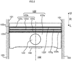
- Fig. 1 is a cross-sectional view schematically showing an engine 150 according to an embodiment of the present teaching.
- R represents the reciprocating direction of a piston part 122.
- U represents the upward direction, which means the direction away from a cylinder body part 100 and toward a cylinder head 130.
- L represents the downward direction, which means the direction away from the cylinder body part 100 and toward a crank case 110.
- the present teaching is not limited thereto and also applicable to air-cooled type engines.
- no particular limitation is put on the number of cylinders of an engine, though this embodiment describes a single-cylinder engine.
- the engine of this embodiment is a four-stroke engine, but instead it may be a two-stroke engine.
- the engine 150 includes the crank case 110, the cylinder body part 100, and the cylinder head 130.
- this embodiment illustrates the cylinder body part 100 and the crank case 110 configured as separate bodies, the cylinder body part 100 and the crank case 110 of the present teaching may be integrated as a single body.
- the crank case 110 has a crankshaft 111 arranged therein.
- the crankshaft 111 includes a crank pin 112 and a crank web 113.
- the cylinder body part 100 is provided above the crank case 110.
- the cylinder body part 100 includes a cylinder wall 103 and an outer wall 104.
- the cylinder wall 103 has a generally cylindrical shape.
- the cylinder wall 103 is formed so as to define a cylinder bore 102.
- the outer wall 104 which encloses the cylinder wall 103, forms an outer contour of the cylinder body part 100.
- a water jacket 105 is provided between the cylinder wall 103 and the outer wall 104.
- the piston part 122 is received in the cylinder bore 102 of the cylinder body part 100.
- the piston part 122 is configured to slide within the cylinder bore 102 while being in contact with a sliding surface 101 of the cylinder body part 100 (see Fig. 2 ).
- the piston part 122 is made of, for example, an Al alloy (typically, an Si-containing Al alloy).
- the piston part 122 is formed by, for example, forging as disclosed in the specification of United States Patent No. 6205836 .
- a process for manufacturing the piston part 122 is not particularly limited.
- the piston part 122 may be formed by casting.
- No cylinder sleeve is provided in the cylinder bore 102. No plating is applied to an inner surface of the cylinder wall 103 of the cylinder body part 100.
- This embodiment which requires no cylinder sleeve, can simplify a process for manufacturing the engine 150, reduce the weight of the engine 150, and improve cooling performance. In addition, since no plating need be applied to the inner surface of the cylinder wall 103, manufacturing costs can be reduced.
- the present teaching is not limited to this embodiment, and it may also be acceptable that, for example, a cylinder sleeve including the cylinder body part 100 of this embodiment is provided in the cylinder bore 102.
- the cylinder sleeve includes the sliding surface 101 of this embodiment. No plating is applied to an inner surface of the cylinder body part 100 included in the cylinder sleeve.
- the cylinder head 130 is provided on the cylinder body part 100.
- the cylinder head 130 in combination with the piston part 122 of the cylinder body part 100, defines a combustion chamber 131.
- the cylinder head 130 includes an intake port 132 and an exhaust port 133.
- an intake valve 134 is arranged for supply of a mixed gas into the combustion chamber 131.
- an exhaust valve 135 is arranged for exhaust in the combustion chamber 131.
- the piston part 122 and the crankshaft 111 are coupled to each other via a connecting rod 140. More specifically, a piston pin 123 of the piston part 122 is inserted through a through hole provided in a small-end portion 142 of the connecting rod 140, and a crank pin 112 of the crankshaft 111 is inserted through a through hole provided in a large-end portion 144 of the connecting rod 140, thereby coupling the piston part 122 to the crankshaft 111.
- a roller bearing (rolling-element bearing) 114 is provided between the crank pin 112 and an inner peripheral surface of the through hole of the large-end portion 144.
- the engine 150 is not provided with an oil pump configured to forcibly feed a lubricant, the engine of the present teaching may be provided with an oil pump.
- Fig. 2 is a side view schematically showing the piston part 122 included in the engine 150 shown in Fig. 1 .
- the piston part 122 is arranged in the cylinder bore 102.
- the piston part 122 includes a piston main body 122a and a piston ring part 122b.
- the piston main body 122a includes the piston pin 123 for insertion into the through hole of the connecting rod 140.
- the piston ring part 122b includes three (a plurality of) piston rings 122c, 122d, and 122e which are arranged on the outer periphery of the piston main body 122a.
- the piston ring 122c which is also referred to as a top ring, is fitted in a top ring groove 122f formed in the outer periphery of the piston main body 122a.
- the piston ring 122d which is also referred to as a second ring, is fitted in a second ring groove 122g formed in the outer periphery of the piston main body 122a.
- the piston ring 122e which is also referred to as an oil ring, is fitted in an oil ring groove 122h formed in the outer periphery of the piston main body 122a.
- the top ring 122c, the second ring 122d, and the oil ring 122e are arranged at intervals and in this sequence from top to down with respect to the reciprocating direction R of the piston part 122.
- an upper end 122m of the piston ring part 122b with respect to the reciprocating direction R of the piston part 122 corresponds to an upper surface of the top ring 122c.
- a lower end 122n of the piston ring part 122b corresponds to a lower surface of the oil ring 122e.
- the piston ring part 122b (the piston rings 122c, 122d, 122e) is in contact with the sliding surface 101 of the cylinder wall 103.
- this embodiment illustrates the piston ring part 122b including three piston rings, the number of piston rings included in the piston ring part 122b is not particularly limited.
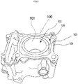
- Fig. 3 is a perspective view schematically showing the cylinder body part 100 included in the engine 150 shown in Fig. 1 .
- Fig. 4 is a cross-sectional view schematically showing the cylinder body part 100 shown in Fig. 3 .
- the cylinder body part 100 which includes the sliding surface 101, is made of an Si-containing Al alloy. It more specifically is made of an Al alloy with an Si content of 16% by mass or more. Preferably, the Al alloy has an Al content of 73.4% by mass or more and 79.6% by mass or less, an Si content of 16% by mass or more and 24% by mass or less, and a copper content of 2.0% by mass or more and 5.0% by mass or less.
- the wear resistance and strength of the cylinder body part 100 can be increased. It is also preferable that the Si content is 18% by mass or more. It is also preferable that the Si content is 22% by mass or less.
- the Al alloy has a phosphorus content of 50 ppm by mass or more and 200 ppm by mass or less, and a calcium content of 0.01% by mass or less.
- the Al alloy having a phosphorus content of 50 ppm by mass or more and 200 ppm by mass or less can suppress coarsening of Si crystal grains, thus allowing the Si crystal grains to be uniformly dispersed in the alloy.
- the Al alloy having a calcium content of 0.01% by mass or less can ensure that an effect of refining the Si crystal grains be exerted by phosphorus, so that a metallographic structure with an excellent wear resistance is obtained.
- the cylinder body part 100 includes the cylinder wall 103 provided with the sliding surface 101, and the outer wall 104 provided with an exposed surface on the outer periphery thereof.
- the water jacket 105 is provided between the cylinder wall 103 and the outer wall 104.
- the water jacket 105 is configured to hold a cooling liquid.
- the cylinder body part 100 includes the sliding surface 101 to be contacted by the piston part 122 (see Fig. 1 ).
- the sliding surface 101 is a surface (an inner peripheral surface) of the cylinder wall 103 on the cylinder bore 102 side.
- the sliding surface 101 is the innermost surface of the inner peripheral surface of the cylinder wall 103 with respect to the radial direction of the cylinder body part 100.
- contact of the sliding surface 101 with the piston part 122 includes contact of the sliding surface 101 with the piston part 122 with interposition of an oil film formed by the lubricant.
- the "upper side” of the sliding surface 101 means the cylinder head side (the top-dead-center side).
- the “lower side” of the sliding surface 101 means the crank case side (the bottom-dead-center side).
- An upper quarter region 101a of the sliding surface 101 means a region closest to the cylinder head among four regions obtained by equally dividing the entire sliding surface 101 into four with respect to the piston sliding direction (the central axis direction of the cylinder bore 102).
- a lower quarter region 101b of the sliding surface 101 means a region closest to the crank case.
- linear grooves 8 are formed throughout the sliding surface 101.
- the present teaching is not limited to this example. In the present teaching, it suffices that a portion where the linear grooves 8 are formed is at least the upper quarter region 101a of the sliding surface 101.
- the portion where the linear grooves 8 are formed may be only the upper quarter region 101a of the sliding surface 101, or alternatively may be the upper quarter region 101a and the lower quarter region 101b of the sliding surface 101.
- Fig. 5 is a plan view schematically showing, on an enlarged scale, the sliding surface of the cylinder body part 100 shown in Fig. 3 .
- R represents the reciprocating direction of the piston part 122.
- Figs. 6(a) and 6(b) are cross-sectional views each schematically showing, on an enlarged scale, the sliding surface of the cylinder body part 100 shown in Fig. 3 .
- the cross-sections shown in Figs. 6(a) and 6(b) are along the direction R.
- Figs. 6(a) and 6(b) for illustrative convenience, only first linear grooves 8a of the linear grooves 8 are shown.
- Si primary crystal grains 1 On the sliding surface 101, a plurality of Si primary crystal grains 1, a plurality of Si eutectic crystal grains 2, and an Al alloy base material 3 are exposed.
- Si crystal grains that are first deposited upon cooling of a molten Al-Si based alloy having a hypereutectic composition are called "Si primary crystal grains”.
- Si crystal grains that are subsequently deposited are called "Si eutectic crystal grains”.
- the Si primary crystal grain 1 is relatively large, and has a granular shape for example.
- the Si eutectic crystal grain 2 is relatively small, and has an acicular shape for example. Not all of the Si eutectic crystal grains 2 have acicular shape.
- Some of the Si eutectic crystal grains 2 may have granular shapes.
- acicular Si eutectic crystal grains 2 among the plurality of Si eutectic crystal grains 2 serve as main crystal grains.
- the Al alloy base material 3 is a solid solution matrix containing Al.
- the cylinder body part 100 includes the plurality of Si primary crystal grains 1, the plurality of Si eutectic crystal grains 2, and the Al alloy base material 3.
- the plurality of Si primary crystal grains 1 and the plurality of Si eutectic crystal grains 2 are dispersed in the Al alloy base material 3.
- the average crystal grain diameter of the Si primary crystal grains 1 is, for example, 8 ⁇ m or more and 50 ⁇ m or less. A sufficient number of Si primary crystal grains 1 exist per unit area of the sliding surface 101. Each of the Si primary crystal grains 1, therefore, receives a relatively low load during operation of the engine 150. Breakdown of the Si primary crystal grains 1 during operation of the engine 150 is suppressed. A portion of each Si primary crystal grain 1 embedded in the Al alloy base material 3 is large enough to make the Si primary crystal grain 1 less likely to fall off. This leads to reduction of wear of the sliding surface 101, which may be caused by fallen Si primary crystal grains 1.
- the average crystal grain diameter of the Si primary crystal grains 1 is less than 8 ⁇ m, a portion of the Si primary crystal grain 1 embedded in the Al alloy base material 3 is small. The Si primary crystal grain 1 is therefore likely to fall off during operation of the engine 150. Since fallen Si primary crystal grains 1 act as abrasive particles, much wear of the sliding surface 101 may occur. If the average crystal grain diameter of the Si primary crystal grains 1 is more than 50 ⁇ m, the number of Si primary crystal grains 1 existing per unit area of the sliding surface 101 is small. Each of the Si primary crystal grains 1, therefore, receives a high load during operation of the engine 150, which may cause breakdown of the Si primary crystal grains 1. Since fragments of broken-down Si primary crystal grains 1 act as abrasive particles, much wear of the sliding surface 101 may occur. It is preferable that the average crystal grain diameter of the Si primary crystal grains 1 is 12 ⁇ m or more.
- the cylinder body part 100 is made of an Al alloy with an Si content of 16% by mass or more and formed by a high-pressure die casting process (HPDC).
- HPDC high-pressure die casting process
- the high-pressure die casting process is a casting process in which a pressure is applied to a molten so that the molten is supplied into a die under a pressure greater than atmospheric pressure.
- a portion to be the sliding surface 101 can be cooled at a high cooling speed (e.g., 4°C/sec or more and 50°C/sec or less). This makes it possible that, for example, the average crystal grain diameter of the Si primary crystal grains 1 is controlled to be 8 ⁇ m or more and 50 ⁇ m or less.
- the average crystal grain diameter of the Si eutectic crystal grains 2 is less than the average crystal grain diameter of the Si primary crystal grains 1.
- the average crystal grain diameter of the Si eutectic crystal grains 2 is 7.5 ⁇ m or less.
- the Si eutectic crystal grains 2 serve to reinforce the Al alloy base material 3. Refining the Si eutectic crystal grains 2 leads to improvement in the wear resistance and strength of the cylinder body part 100.
- Fig. 7 is a graph showing a preferred example of the grain size distribution of the Si crystal grains.
- an Si crystal grain having a crystal grain diameter of 1 ⁇ m to 7.5 ⁇ m is an Si eutectic crystal grain 2
- an Si crystal grain having a crystal grain diameter of 8 ⁇ m to 50 ⁇ m is an Si primary crystal grain 1.
- the Si crystal grains 1, 2 of the cylinder body part 100 have a grain size distribution in which peaks appear where the crystal grain diameter is in a range of 1 ⁇ m to 7.5 ⁇ m and in a range of 8 ⁇ m to 50 ⁇ m.
- the wear resistance and strength of the cylinder body part 100 can be highly improved.
- the frequency at a first peak (a peak due to the Si eutectic crystal grains 2) in the crystal grain diameter range of 1 ⁇ m to 7.5 ⁇ m is five times greater than the frequency at a second peak (a peak due to the Si primary crystal grains 1) in the crystal grain diameter range of 8 ⁇ m to 50 ⁇ m.
- step S1c As a way to control the average crystal grain diameters of the Si primary crystal grains 1 and the Si eutectic crystal grains 2, it is conceivable to adjust the speed of cooling a portion to be the sliding surface 101 in the step of forming a molded body by casting (below-described step S1c).
- casting is performed such that a portion to be the sliding surface 101 is cooled at a cooling speed of, for example, 4°C/sec or more and 50°C/sec or less, thus enabling the Si crystal grains 1 and 2 to be deposited with the Si primary crystal grains 1 having an average crystal grain diameter of 8 ⁇ m or more and 50 ⁇ m or less and the Si eutectic crystal grains 2 having an average crystal grain diameter of 7.5 ⁇ m or less.
- a plurality of linear grooves 8 are formed in the sliding surface 101.
- the plurality of linear grooves 8 include a plurality of first linear grooves 8a and a plurality of second linear grooves 8b.
- the plurality of first linear grooves 8a which are shaped so as to extend from the upper left to the lower right in Fig. 5 , are substantially in parallel with one another.
- the plurality of first linear grooves 8a form a striped pattern on the sliding surface 101.
- the plurality of second linear grooves 8b which are shaped so as to extend from the upper right to the lower left in Fig. 5 , are substantially in parallel with one another.
- the plurality of second linear grooves 8b form a striped pattern on the sliding surface 101.
- the plurality of first linear grooves 8a and the plurality of second linear grooves 8b are not in parallel but intersect with each other.
- the plurality of linear grooves 8 form a lattice pattern on the sliding surface 101.
- portions where the Si primary crystal grains 1 and/or the Si eutectic crystal grains 2 overlap the linear grooves 8 indicate portions where the linear grooves 8 are formed so as to pass over exposed surfaces of the Si primary crystal grains 1 and/or the Si eutectic crystal grains 2. At least a part of these portions has a fracture surface 5a as shown in Fig. 6(b) .
- At least two linear grooves 8 of the plurality of linear grooves 8 are substantially in parallel with each other. Some linear grooves 8 (the first linear grooves 8a) and the other linear grooves 8 (the second linear grooves 8b) of the plurality of linear grooves 8 may intersect with each other. It may also be acceptable that the plurality of linear grooves 8 are formed such that none of them intersect but all of them are substantially in parallel with one another.
- being “substantially in parallel” means a state where adjacent linear grooves 8 extend without crossing each other. The meaning of being “substantially in parallel” can therefore be interpreted as follows.
- adjacent linear grooves 8 are, in a strict sense, not in parallel with each other because of errors, misalignments, etc., caused during formation of the linear grooves 8; in the present teaching, the adjacent linear grooves 8 can be considered to be substantially in parallel with each other.
- a set of first linear grooves 8a and a set of second linear grooves 8b are provided as sets of parallel linear grooves in the sliding surface 101
- the number of sets of parallel linear grooves is not particularly limited in the present teaching. Grooves belonging to different sets intersect with each other.
- a pattern formed by the plurality of linear grooves 8 provided in the sliding surface 101 is not limited to a square lattice pattern as shown in Fig. 5 .
- a pattern formed by the plurality of linear grooves 8 may be a striped pattern as formed by the first linear grooves 8a or the second linear grooves 8b, or may be a polygonal lattice pattern such as a triangular lattice pattern.
- the square lattice pattern is an example of the polygonal lattice pattern.
- the pitch of grooves may not necessarily be constant.
- the plurality of linear grooves 8 form a regular pattern (a striped pattern, a polygonal lattice pattern, etc.).
- the Al alloy base material 3 as well as the Si primary crystal grains 1 included in the regular pattern is exposed on the sliding surface 101 such that it is contactable with the piston ring part 122b (the piston part 122).
- the sliding surface 101 having the linear grooves 8 formed therein in the regular pattern enables a lubricant to be dispersed with an improved uniformity, as compared with a conventional irregular sliding surface (a sliding surface on which Si crystal grains are exposed in the form of floating islands).
- an oil film formed on the sliding surface 101 has a high uniformity.
- descriptions of the linear grooves 8 apply to both the first linear grooves 8a and the second linear grooves 8b, except where the first linear grooves 8a and the second linear grooves 8b are distinguished from each other.
- the linear grooves 8 have straight-line shapes in a plan view, as shown in Fig. 5 .
- the shapes of the linear grooves 8 in a plan view are not limited to straight-line shapes, and it suffices that they are line-like shapes extending substantially in parallel with one another such that adjacent linear grooves 8 do not intersect.
- the linear groove 8 may include a portion with a curved-line shape and a portion with a straight-line shape.
- the linear groove 8 may include a flexed portion.
- the plurality of linear grooves 8 may have different shapes in a plan view.
- All of the linear grooves 8 may have identical or substantially identical shapes in a plan view. It is not always necessary that each of the plurality of linear grooves 8 is formed continuous throughout the entire sliding surface 101. It is not always necessary that each of the plurality of linear grooves 8 extends to an end edge of the sliding surface 101. It may be acceptable that each of the plurality of linear grooves 8 includes a discontinuous portion on the sliding surface 101.
- the width of the linear groove 8 is less than the thickness of the thinnest one of the piston rings 122c, 122d, and 122e.
- the width of the linear groove 8 is equal to or more than the average crystal grain diameter of the Si primary crystal grains 1.
- the width of the linear groove 8 is equal to or more than a maximum value of the grain diameter range of the Si primary crystal grains 1 in the grain size distribution in the cylinder body part 100.
- Fig. 5 illustrates the linear grooves 8 having a fixed width, this example does not limit the present teaching. It may be acceptable that the width of the linear groove 8 varies depending on its location. It may also be acceptable that the plurality of linear grooves 8 have different widths. It may also be acceptable that all of the linear grooves 8 have the same width or substantially the same width.
- the linear groove 8 of this embodiment has a depth equal to or more than one-third of the upper limit value of the grain diameter range of the Si eutectic crystal grains 2 in the grain size distribution of the Si crystal grains in the cylinder body part 100.
- Patent Literature 3 discloses a technique for suppressing generation of scuffs at or near the top dead center more effectively.
- a sliding surface is etched, and an Al alloy base material is removed in the depth direction substantially uniformly over the entire sliding surface except its regions having Si crystal grains which exist in the form of floating islands.
- the linear grooves 8 are formed at a pitch greater than the average crystal grain diameter of the Si primary crystal grains, and thus a limited amount of the Al alloy base material is removed. It is therefore possible to form the linear grooves 8 having a relatively large depth.
- the linear grooves 8 of this embodiment have a depth equal to or more than one-third of the upper limit value of the grain diameter range of the Si eutectic crystal grains 2 which generally have acicular shapes, but fall-off of the Si eutectic crystal grains 2 is prevented or suppressed. Since the average crystal grain diameter of the Si primary crystal grains 1 is larger than the average crystal grain diameter of the Si eutectic crystal grains 2, fall-off of the Si primary crystal grains 1 is also prevented or suppressed. Since the plurality of substantially parallel linear grooves with a relatively large depth are formed in the sliding surface, a large amount of lubricant can be retained, so that the uniformity of dispersion of the lubricant is improved.
- the linear groove 8 has a depth of 2.0 ⁇ m or more. It may be acceptable that the linear groove 8 has a depth of 40% or more of the upper limit value of the grain diameter range of the Si eutectic crystal grains 2 in the grain size distribution of the Si crystal grains in the cylinder body part 100. It may also have a depth equal to or more than one-half of the upper limit value of the grain diameter range of the Si eutectic crystal grains 2 in the grain size distribution of the Si crystal grains in the cylinder body part 100.
- the linear grooves 8 have a depth less than the upper limit value of the grain diameter range of the Si eutectic crystal grains 2. This allows the lubricant retained in the linear grooves 8 to be appropriately and efficiently supplied to the sliding surface 101. It is preferable that the linear grooves 8 have a depth of 6.0 ⁇ m or less.
- a groove having a depth less than the lower limit value of the depth of the linear groove 8 and/or a groove having a depth more than the upper limit value of the depth of the linear groove 8 may be formed in the sliding surface 101.
- it may be acceptable that a groove other than the linear groove defined in the present teaching is formed in the sliding surface.
- the linear groove 8 has such a cross-sectional shape that the width of the linear groove 8 decreases as the depth of the linear groove 8 increases.
- the cross-sectional shape of the linear groove 8 means the shape of a cross-section of the linear groove 8 in a plane perpendicular to the direction in which the linear groove 8 extends.
- the cross-sectional shape of the linear groove 8 is not particularly limited.
- the cross-sectional shape of the linear groove 8 may be, for example, generally U-shaped or generally V-shaped as shown in Fig. 6(a) . It is not necessary that all the cross-sections of the linear grooves 8 have identical shapes. Different portions of the linear groove 8 may have different cross-sectional shapes, or different linear grooves 8 may have different cross-sectional shapes.
- a portion (ridge) between linear grooves 8 may not necessarily have a flat surface as shown in Figs. 5 , 6(a), and 6(b) .
- the portion between linear grooves 8 may have an inclined surface or may form a ridge line.
- One or more grooves having a depth less than the depth of the linear groove 8 may be formed.
- the plurality of first linear grooves 8a that are substantially in parallel are formed at a pitch greater than the average crystal grain diameter of the Si primary crystal grains 1.
- the plurality of Si primary crystal grains 1 exists between adjacent first linear grooves 8a.
- both the Si primary crystal grain 1 and the Al alloy base material 3 are exposed on the sliding surface 101 in a region between adjacent first linear grooves 8a such that both the Si primary crystal grain 1 and the Al alloy base material 3 are contactable with the piston part 122. Since the portion of the sliding surface 101 contactable with the piston part 122 is adjacent to the first linear grooves 8a in a plan view, a lubricant can be smoothly supplied to the sliding surface 101.
- Fig. 5 illustrates a case where a pair of adjacent first linear grooves 8a extend at a constant pitch irrespective of location, this example does not limit the present teaching.
- the pitch of the pair of adjacent first linear grooves 8a may not necessarily be constant.
- each of adjacent first linear grooves 8a is formed in a meandering shape so that the pitch of the first linear grooves 8a varies depending on location. While the above descriptions are for the first linear grooves 8a, the same descriptions as those of the first linear grooves 8a apply to the second linear grooves 8b, and therefore descriptions of the second linear grooves 8b are omitted herein.
- At least one of the linear grooves 8 passes through an Si primary crystal grain 1 while breaking down the Si primary crystal grain 1. That is, at least one of the linear grooves 8 is formed so as to pass over an exposed surface of an Si primary crystal grain 1. This provides a further enhanced uniformity of dispersion of the lubricant on the sliding surface 101.
- the present teaching is not limited to this example.
- the Si primary crystal grain 1 having the fracture surface 5a is exposed on the sliding surface 101. That is, in this embodiment, the Si primary crystal grain 1 exposed on the sliding surface 101 is at least partially broken down, and a surface (which means the fracture surface 5a) that appears on the Si primary crystal grain 1 as a result of the breakdown is exposed on the sliding surface 101. In this manner, an oil reservoir 5b is formed in the sliding surface 101. Since the fracture surface of the Si primary crystal grain 1 is textured, the oil reservoir 5b is capable of retaining a large amount of lubricant. The open area of the oil reservoir 5b is comparable with the cross-sectional area of the Si primary crystal grain 1 (the area of a portion exposed on the sliding surface 101).
- the depth of the oil reservoir 5b is less than the diameter of the Si primary crystal grain 1. Not only the plurality of first linear grooves 8a that are substantially in parallel with one another but also the oil reservoirs 5b including the fracture surfaces 5a of the Si primary crystal grains 1 are formed in the sliding surface 101. This enables an increased amount of lubricant to be retained while maintaining the uniformity of dispersion of the lubricant. Generation of scuffs can be suppressed more effectively.
- the fracture surfaces 5a are formed during a surface treatment performed on the cylinder body part 100, the surface treatment being performed after the cylinder body part 100 is formed by the casting process. More specifically, for example, the fracture surfaces 5a are formed while the Si primary crystal grains 1 are honed with a grinding stone.
- the cylinder body part 100 is made of an Al alloy with an Si content of 16% by mass or more.
- the average crystal grain diameter of the Si primary crystal grains 1 exposed on the upper quarter region 101a of the sliding surface 101 is 8 ⁇ m or more and 50 ⁇ m or less.
- the Si primary crystal grains 1 are given appropriate sizes and distributed appropriately over the sliding surface.
- the Si primary crystal grains 1 and the Al alloy base material 3 are exposed so as to be contactable with the piston part 122, and moreover the plurality of substantially parallel linear grooves 8 (the first linear grooves 8a and the second linear grooves 8b) having a depth equal to or more than one-third of the upper limit value of the grain diameter range of the Si eutectic crystal grains 2 in the grain size distribution of the Si crystal grains in the cylinder body part 100 are formed at a pitch greater than the average crystal grain diameter of the Si primary crystal grains 1. Since the plurality of substantially parallel linear grooves 8 are formed at a pitch greater than the average crystal grain diameter of the Si primary crystal grains 1, the uniformity of dispersion of the lubricant on the sliding surface 101 can be improved.
- the uniformity of the oil film formed on the sliding surface can be enhanced.
- a sufficient amount of lubricant can be retained in the linear grooves 8, because the plurality of linear grooves 8 have a depth equal to or more than one-third of the upper limit value of the grain diameter range of the Si eutectic crystal grains 2 in the grain size distribution of the Si crystal grains in the cylinder body part 100. Accordingly, discontinuity of the oil film on the sliding surface can be suppressed.
- the plurality of linear grooves 8 have portions that extend between adjacent Si primary crystal grains 1.
- the Al alloy base material 3 is exposed on the sliding surface 101 so as to be contactable with the piston part 122.
- Contact of the Al alloy base material 3 with the piston part 122 has conventionally been considered to be undesirable from the viewpoint of suppression of generation of scuffs.
- the Al alloy base material 3 as well as the Si primary crystal grains 1, which have appropriate sizes and are distributed appropriately over the sliding surface 101 is exposed on the sliding surface 101.
- the uniformity of the oil film formed on the sliding surface 101 is enhanced while a sufficient amount of lubricant is retained, as described above.
- An influence of contact of the Al alloy base material 3 with the piston part 122 is accordingly reduced to an acceptable level, and the improved uniformity of the oil film exerts an anti-scuff effect. In this manner, generation of scuffs can be suppressed more effectively.
- the cylinder body part 100 is manufactured by, for example, performing the following steps S1 to S4 in order:
- a molded body made of an Si-containing Al alloy is prepared (step S1).
- the molded body includes, near a surface thereof, Si primary crystal grains and Si eutectic crystal grains.
- the step S1 of preparing the molded body includes, for example, steps S1a to S1e:
- an Si-containing Al alloy is prepared (step S1a).
- an Al alloy having an Al content of 73.4% by mass or more and 79.6% by mass or less, an Si content of 16% by mass or more and 24% by mass or less, and a copper content of 2.0% by mass or more and 5.0% by mass or less.
- the Al alloy thus prepared is heated and melted in a melting furnace, to form a molten (step S1b). It is preferable that about 100 ppm by mass of phosphorus is added to an unmelted Al alloy beforehand or to the molten.
- the Al alloy having a phosphorus content of 50 ppm by mass or more and 200 ppm by mass or less can suppress coarsening of Si crystal grains, thus allowing the Si crystal grains to be uniformly dispersed in the alloy.
- the Al alloy having a calcium content of 0.01% by mass or less can ensure that an effect of refining the Si crystal grains be exerted by phosphorus, so that a metallographic structure with an excellent wear resistance is obtained. For these reasons, it is preferable that the Al alloy has a phosphorus content of 50 ppm by mass or more and 200 ppm by mass or less and a calcium content of 0.01% by mass or less.
- a high-pressure die casting process is performed to cast the molten Al alloy (step S1c).
- the molten is cooled in a casting mold, to form a molded body.
- a portion of the cylinder wall 103 to be the sliding surface 101 is cooled at a high cooling speed (e.g., 4°C/sec or more and 50°C/sec or less), so that a molded body including, near its surface, Si crystal grains which contribute to the wear resistance is obtained.
- a casting apparatus disclosed in the WO2004/002658 pamphlet can be used, for example.
- T5 treatment is a treatment in which a molded body is quenched by water-cooling, etc. immediately after removed from a casting mold, then subjected to artificial aging at a predetermined temperature for a predetermined period for the purpose of improving mechanical properties and obtaining dimensional stabilization, and then air-cooled.
- T6 treatment is a treatment in which a molded body is subjected to a solution treatment at a predetermined temperature for a predetermined period after removed from a casting mold, then water-cooled, then subjected to an artificial aging treatment at a predetermined temperature for a predetermined period, and then air-cooled.
- T7 treatment which is a treatment in which overaging is made as compared with T6 treatment, is able to provide more dimensional stabilization than T6 treatment is, but can provide less hardness than T6 treatment can.
- a predetermined machining process is performed on the molded body (step S1e). More specifically, a mating surface for mating with a cylinder head and a mating surface for mating with a crank case are ground, for example.
- a fine boring process is performed on a surface of the molded body, and more specifically on an inner peripheral surface (that is, a surface to be the sliding surface 101) of the cylinder wall 103, for the purpose of adjusting dimensional accuracy (step S2).
- the surface having the fine boring process performed thereon is subjected to a rough honing treatment (step S3).
- the surface to be the sliding surface 101 is polished with a grinding stone of relatively low count (a grinding stone having large abrasive particles).
- the rough honing treatment is performed throughout a region of the molded body to be the sliding surface 101, but the present teaching is not limited to this example. In the present teaching, it suffices that the rough honing treatment is performed at least on the upper quarter region of the sliding surface 101.
- a finishing honing treatment is performed (step S4).
- a region to be the sliding surface 101 is polished with a grinding stone of relatively high count (a grinding stone having small abrasive particles).
- the rough honing treatment and the finishing honing treatment can be implemented by using, for example, a honing apparatus disclosed in Japanese Patent Application Laid-Open No. 2004-268179 .
- Specifications e.g., the type of the abrasive particles, the count (abrasive particle diameter), the type of a bonding agent, etc.
- the grinding stones used in the rough honing treatment and the finishing honing treatment can be set according to specifications of the linear grooves 8 to be formed in the sliding surface 101.
- the sliding surface 101 of this embodiment is formed through the above-described steps.
- the plurality of Si primary crystal grains 1 and the Al alloy base material 3 are exposed on the sliding surface 101.
- the piston part 122 is reciprocating in the cylinder bore 102, the plurality of Si primary crystal grains 1 and the Al alloy base material 3 are contacted by the piston part 122.
- the sliding surface 101 has the plurality of linear grooves 8 that are formed at least in the upper quarter region of the sliding surface 101.
- the plurality of linear grooves 8 include the plurality of substantially parallel first linear grooves 8a and the plurality of substantially parallel second linear grooves 8b.
- the linear grooves 8 are formed by using a grinding stone, but the present teaching is not limited to this example.
- the linear grooves 8 may be formed by using laser, for example.
- the number of times the rough honing treatment and the finishing honing treatment are performed is not limited to one, and they can be performed twice or more.
- the cylinder body member of this embodiment is itself the above-described cylinder body part 100 (see Fig. 1 , etc.).
- the cylinder body part 100 is a part including the sliding surface 101.
- the cylinder body member of the present teaching is not limited to this example. It suffices that the cylinder body member is provided with the cylinder body part 100 including the sliding surface 101.
- the cylinder body member of the present teaching may be a member (a so-called cylinder block) constituted of the cylinder body part 100 and the crank case 110 formed integrally with each other.
- the cylinder body member of the present teaching may be a cylinder sleeve that is installed in the cylinder bore 102 when used. Since the cylinder body member includes the above-described sliding surface 101, application of the cylinder body member to an engine enables more effective suppression of generation of scuffs (particularly at or near the top dead center) in the engine.
- the vehicle of the present teaching includes various types of vehicles such as automobiles, motorcycles, snowcats as exemplified by snowmobiles, and the like.
- the number of wheels is not particularly limited to, for example, four, three, or two.
- the vehicle of the present teaching may be a box-type vehicle in which an engine is arranged in a place, such as an engine room, distant from a seat, or may be a straddled vehicle in which an engine is at least partially arranged below a seat straddled by a driver.
- the straddled vehicle includes a scooter-type vehicle that a driver can ride with feet together.
- a motorcycle is illustrated below.
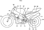
- Fig. 8 is a side view schematically showing a motorcycle including the engine 150 shown in Fig. 1 .
- a head pipe 302 is arranged at the front end of a main body frame 301.
- a front fork 303 is attached to the head pipe 302, so as to be swingable in the lateral direction of the vehicle.
- a front wheel 304 is rotatably supported at the lower ends of the front fork 303.
- a handlebar 305 is provided at the upper end of the front fork 303.
- a rear frame 306 is provided so as to extend rearward from the upper side of a rear end portion of the main body frame 301.
- a fuel tank 307 is provided above the main body frame 301, and a main seat 308a and a tandem seat 308b are provided above the rear frame 306.
- a rear arm 309 extending rearward is attached to the rear end portion of the main body frame 301.
- a rear wheel 310 is rotatably supported at the rear end of the rear arm 309.
- the engine 150 shown in Fig. 1 is held in a middle portion of the main body frame 301.
- the engine 150 adopts the cylinder body part 100 of this embodiment.
- a radiator 311 is provided on the front side of the engine 150.
- An exhaust tube 312 is connected to the exhaust port of the engine 150.
- a muffler 313 is attached to the rear end of the exhaust tube 312.
- the engine 150 is coupled with a transmission 315.
- the transmission 315 has an output shaft 316 to which a drive sprocket 317 is attached.
- the drive sprocket 317 is coupled to a rear-wheel sprocket 319 of the rear wheel 310 via a chain 318.
- the transmission 315 and the chain 318 function as a transmission mechanism for transmitting power generated by the engine 150 to a drive wheel.
- the motorcycle (vehicle) of this embodiment which is mounted with the engine 150 including the cylinder body part 100 with the sliding surface 101, is able to suppress generation of scuffs, particularly at or near the top dead center, more effectively.
- the average crystal grain diameters of the Si primary crystal grains and the Si eutectic crystal grains are measured by applying image processing to a portion of the cylinder body part to be the sliding surface. Based on the area of each Si crystal grain in an image obtained by the image processing, the diameter (equivalent diameter) of the Si crystal grain is calculated, assuming that the Si crystal grain in the image is in the shape of a true circle. A fine crystal having a diameter of less than 1 ⁇ m is not counted as the Si crystal grain (neither the Si primary crystal grain nor the Si eutectic crystal grain). In this manner, the number (frequency) and the diameters of the Si crystal grains are identified. Based on them, a grain size distribution of the Si crystal grains in the cylinder body part is obtained.
- the grain size distribution is, for example, a histogram as shown in Fig. 7 .
- the grain size distribution has two peaks.
- the grain size distribution is divided into two regions, the threshold for the division being the diameter value corresponding to a valley portion between the two peaks.
- a region corresponding to a larger diameter is defined as a grain size distribution of the Si primary crystal grains.
- a region corresponding to a smaller diameter is defined as a grain size distribution of the Si eutectic crystal grains.
- the average crystal grain diameter of the Si primary crystal grains and the average crystal grain diameter of the Si eutectic crystal grains are calculated based on the grain size distributions, respectively.
- the width of the linear groove is the distance between a pair of adjacent ridge lines in a cross-section (profile curve) across the linear groove.
- the cross-section is in parallel with the direction in which the piston part slides relative to the sliding surface (the reciprocating direction R of the piston part).
- the cross-section is also in parallel with the radial direction of the cylinder body part.
- the depth of the linear groove is the depth from the higher one of a pair of ridge lines that are adjacent to a linear groove to the lowest point of the linear groove.
- the pitch of the linear grooves is the distance between the lowest points of a pair of adjacent grooves in the cross-section (profile curve).
- the width of the linear groove is the distance between edges of a pair of such portions (flat surfaces) of the sliding surface.
- the width, depth, and pitch of the linear grooves respective values averaged over linear grooves included in a profile curve within 3 to 5 mm are adopted.
- a groove other than the linear groove having the depth specified in the present teaching may be formed in the sliding surface.
- the linear grooves having the depth specified in the present teaching are used to identify the width and pitch of the linear grooves.
- the present teaching may be embodied in many different forms.
- the present disclosure is to be considered as providing examples of the principles of the teaching.
- a number of illustrative embodiments are described herein with the understanding that such examples are not intended to limit the teaching to preferred embodiments described herein and/or illustrated herein.
- the present teaching is not limited to the various preferred embodiments described herein.
- the present teaching includes any and all embodiments having equivalent elements, modifications, omissions, combinations (e.g., of aspects across various embodiments), adaptations and/or alterations as would be appreciated by those in the art based on the present disclosure.
- the limitations in the claims are to be interpreted broadly based on the language employed in the claims and not limited to examples described in the present specification or during the prosecution of the application, which examples are to be construed as non-exclusive.
- the term "preferably” is non-exclusive and means "preferably, but not limited to”.
Landscapes
- Chemical & Material Sciences (AREA)
- Engineering & Computer Science (AREA)
- Mechanical Engineering (AREA)
- Materials Engineering (AREA)
- Metallurgy (AREA)
- Organic Chemistry (AREA)
- Physics & Mathematics (AREA)
- Thermal Sciences (AREA)
- Crystallography & Structural Chemistry (AREA)
- Cylinder Crankcases Of Internal Combustion Engines (AREA)
- Pistons, Piston Rings, And Cylinders (AREA)
Abstract
Description
- The present teaching relates to an engine, a cylinder body member, and a vehicle.
- Recently, for the purpose of reducing the weight of an engine, alloying a cylinder body part with Al is becoming more popular. The cylinder body part needs to have a high strength and a high wear resistance. This is why an Al alloy with a high Si content, which means a hypereutectic Al-Si based alloy, can be one option among Al alloys for making the cylinder body part.
- Patent Literature 1 (PTL1) discloses the following technique which relates to an engine including a cylinder block made of an Al alloy with a relatively high Si content.
- The cylinder block has a sliding surface on which a piston ring is slidable, and Si crystal grains and an Al alloy base material are exposed on the sliding surface. The sliding surface is mechanically processed such that the Si crystal grains emerge thereat. An exposed surface of each Si crystal grain exists more inward of the cylinder than an exposed surface of the Al alloy base material does. Thus, the piston ring comes into contact with the Si crystal grains. Contact of the piston ring with the Al alloy base material is avoided. The cylinder block, which is made of the Al alloy with a relatively high Si content, is manufactured by a high-pressure die casting process. This enables Si primary crystal grains each having an appropriate size to be distributed appropriately over the sliding surface. That is, each Si primary crystal grain receives a reduced load during an engine operation, and therefore breakdown of the Si primary crystal grain is suppressed. In addition, since each Si primary crystal grain has an appropriate size, fall-off of the Si primary crystal grains from the sliding surface is suppressed. Accordingly, contact of the piston ring with the Al alloy base material is effectively avoided. This can suppress generation of scuffs which may be caused by contact between the Al alloy base material and the piston ring. Moreover, a lubricant is retained between the Si crystal grains which emerge at the sliding surface, and recesses each formed between the Si crystal grains function as oil reservoirs. This provides an improved lubricity to the piston sliding in the cylinder, so that a scuff resistance of the cylinder body part is improved.
- In the cylinder block of
Patent Literature 1, as described above, the Si primary crystal grains each having an appropriate size are exposed in the form of floating islands on the sliding surface while being distributed with an appropriate density. Accordingly, contact between the Al alloy base material and the piston ring is avoided, and the recesses each formed between the Si crystal grains function as oil reservoirs. As a result, generation of scuffs is suppressed. -
Patent Literatures 2 and 3 (PTLs 2 and 3) as well asPatent Literature 1 relate to an engine including a cylinder block made of an Al alloy with a relatively high Si content. - In the cylinder block of
Patent Literature 2, a sliding surface is etched such that Si crystal grains emerge thereat. Since the etching is given, a surface of an Al alloy base material is textured in its portion located in each recess between the Si crystal grains. This enables the recess between the Si crystal grains to retain a larger amount of lubricant, as compared with the cylinder block ofPatent Literature 1. Accordingly, generation of scuffs is suppressed more effectively. - In the cylinder block of
Patent Literature 3, a sliding surface is etched such that a surface of an Al alloy base material is textured more deeply in its portion located in each recess between Si crystal grains at or near the top dead center. This can increase the amount of lubricant retained in each recess between the Si crystal grains at or near the top dead center. Generation of scuffs at or near the top dead center is suppressed more effectively. - At or near the top dead center, a lubrication between a sliding surface and a piston part is mostly a boundary lubrication. The top dead center is close to a combustion chamber of an engine. Lubrication conditions are therefore severe at or near the top dead center. Scuffs tend to be generated at or near the top dead center. This is why the technique for suppressing generation of scuffs at or near the top dead center is proposed, as in
Patent Literature 3. - Conventionally, a cylinder block made of an Al alloy with a relatively high Si content and manufactured by a high-pressure die casting process has been upgraded under the presupposition that Si crystal grains are exposed in the form of floating islands. In other words, the technique relating to a cylinder block made of an Al alloy with a relatively high Si content and manufactured by a high-pressure die casting process involves an underlying presupposition that generation of scuffs can be suppressed by achieving the following two conditions:
- suppressing contact between a piston ring and an Al alloy base material; and
- making a recess between Si crystal grains function as an oil reservoir.
-
- PTL 1 : Japanese Patent Application Laid-Open No.
2005-273654 - PTL 2 : Japanese Patent Application Laid-Open No.
2008-180218 - PTL 3 : Japanese Patent Application Laid-Open No.
2010-31840 - An object of the present teaching is to provide an engine, a cylinder body member, and a vehicle that are able to suppress generation of scuffs at or near the top dead center more effectively.
- The present teaching can adopt the following configurations.
- (1) An engine including a piston part and a cylinder body part with a sliding surface on which the piston part is slidable,
the cylinder body part being made of an Al alloy with an Si content of 16% by mass or more, the cylinder body part including Si primary crystal grains, Si eutectic crystal grains, and an Al alloy base material, the Si primary crystal grains having an average crystal grain diameter of 8 µm or more and 50 µm or less, the Si eutectic crystal grains having an average crystal grain diameter less than the average crystal grain diameter of the Si primary crystal grains,
the sliding surface being configured such that, at least in an upper quarter region of the sliding surface, the Si primary crystal grains and the Al alloy base material are exposed so as to be contactable with the piston part, and a plurality of substantially parallel linear grooves are formed at a pitch greater than the average crystal grain diameter of the Si primary crystal grains so that the plurality of substantially parallel linear grooves have a portion that exists between adjacent ones of the Si primary crystal grains, the plurality of substantially parallel linear grooves having a depth equal to or more than one-third of an upper limit value of a diameter range of the Si eutectic crystal grains in a grain size distribution of Si crystal grains in the cylinder body part.
In the configuration of (1), the cylinder body part is made of an Al alloy with an Si content of 16% by mass or more. The average crystal grain diameter of the Si primary crystal grains exposed on the upper quarter region of the sliding surface is 8 µm or more and 50 µm or less. In consideration of receiving a load from the piston part, the Si primary crystal grains are given appropriate sizes and distributed appropriately over the sliding surface. Under such conditions, the Si primary crystal grains and the Al alloy base material are exposed so as to be contactable with the piston part, and a plurality of substantially parallel linear grooves are formed at a pitch greater than the average crystal grain diameter of the Si primary crystal grains, the plurality of substantially parallel linear grooves having a depth equal to or more than one-third of an upper limit value of a diameter range of the Si eutectic crystal grains in a grain size distribution of Si crystal grains in the cylinder body part. Since the plurality of substantially parallel linear grooves are formed at a pitch greater than the average crystal grain diameter of the Si primary crystal grains, uniformity of dispersion of a lubricant on the sliding surface can be improved. As a result, uniformity of an oil film formed on the sliding surface can be enhanced. In addition, a sufficient amount of lubricant can be retained in the grooves, because the plurality of linear grooves have a depth equal to or more than one-third of an upper limit value of a diameter range of the Si eutectic crystal grains in a grain size distribution of Si crystal grains in the cylinder body part. Accordingly, discontinuity of the oil film on the sliding surface can be suppressed. Furthermore, the plurality of linear grooves have a portion that extends between adjacent ones of the Si primary crystal grains. Since a load of the piston part is received by the Si primary crystal grains, wear of the sliding surface (the Al alloy base material) is suppressed in its regions near both sides of the groove, so that the retention of the lubricant in the groove is facilitated.
The A1 alloy base material is exposed on the sliding surface so as to be contactable with the piston part. Contact of the Al alloy base material with the piston part has conventionally been considered to be undesirable from the viewpoint of suppression of generation of scuffs. In the configuration of (1), however, the Al alloy base material as well as the Si primary crystal grains, which have appropriate sizes and are distributed appropriately over the sliding surface, is exposed on the sliding surface. In the configuration of (1), as described above, the uniformity of the oil film formed on the sliding surface is enhanced while a sufficient amount of lubricant is retained. An influence of contact of the Al alloy base material with the piston part is accordingly reduced to an acceptable level, and the improved uniformity of the oil film exerts an anti-scuff effect. In this manner, generation of scuffs can be suppressed more effectively. - (2) An engine including a piston part and a cylinder body part with a sliding surface on which the piston part is slidable,
the cylinder body part being made of an Al alloy with an Si content of 16% by mass or more and formed by a high-pressure die casting process, the cylinder body part including Si primary crystal grains, Si eutectic crystal grains, and an Al alloy base material, the Si eutectic crystal grains having an average crystal grain diameter less than the average crystal grain diameter of the Si primary crystal grains,
the sliding surface being configured such that, at least in an upper quarter region of the sliding surface, the Si primary crystal grains and the Al alloy base material are exposed so as to be contactable with the piston part, and a plurality of substantially parallel linear grooves are formed at a pitch greater than the average crystal grain diameter of the Si primary crystal grains so that the plurality of substantially parallel linear grooves have a portion that exists between adjacent ones of the Si primary crystal grains, the plurality of substantially parallel linear grooves having a depth equal to or more than one-third of an upper limit value of a diameter range of the Si eutectic crystal grains in a grain size distribution of Si crystal grains in the cylinder body part.
In the configuration of (2), the cylinder body part is made of an Al alloy with an Si content of 16% by mass or more and formed by a high-pressure die casting process. In consideration of receiving a load from the piston part, the Si primary crystal grains are given appropriate sizes and distributed appropriately over the sliding surface. Under such conditions, the Si primary crystal grains and the Al alloy base material are exposed so as to be contactable with the piston part, and a plurality of substantially parallel linear grooves are formed at a pitch greater than the average crystal grain diameter of the Si primary crystal grains, the plurality of substantially parallel linear grooves having a depth equal to or more than one-third of an upper limit value of a diameter range of the Si eutectic crystal grains in a grain size distribution of Si crystal grains in the cylinder body part. Since the plurality of substantially parallel linear grooves are formed at a pitch greater than the average crystal grain diameter of the Si primary crystal grains, uniformity of dispersion of a lubricant on the sliding surface can be improved. As a result, uniformity of an oil film formed on the sliding surface can be enhanced. In addition, a sufficient amount of lubricant can be retained in the grooves, because the plurality of linear grooves have a depth equal to or more than one-third of an upper limit value of a diameter range of the Si eutectic crystal grains in a grain size distribution of Si crystal grains in the cylinder body part. Accordingly, discontinuity of the oil film on the sliding surface can be suppressed. Furthermore, the plurality of linear grooves have a portion that extends between adjacent ones of the Si primary crystal grains. Since a load of the piston part is received by the Si primary crystal grains, wear of the sliding surface (the Al alloy base material) is suppressed in its regions near both sides of the groove, so that the retention of the lubricant in the groove is facilitated.
The Al alloy base material is exposed on the sliding surface so as to be contactable with the piston part. Contact of the Al alloy base material with the piston part has conventionally been considered to be undesirable from the viewpoint of suppression of generation of scuffs. In the configuration of (2), however, the Al alloy base material as well as the Si primary crystal grains, which have appropriate sizes and are distributed appropriately over the sliding surface, is exposed on the sliding surface. In the configuration of (2), as described above, the uniformity of the oil film formed on the sliding surface is enhanced while a sufficient amount of lubricant is retained. An influence of contact of the Al alloy base material with the piston part is accordingly reduced to an acceptable level, and the improved uniformity of the oil film exerts an anti-scuff effect. In this manner, generation of scuffs can be suppressed more effectively. - (3) The engine of (1) or (2), in which
the plurality of linear grooves have a depth equal to or more than one-third of an upper limit value of a diameter range of the Si eutectic crystal grains and less than the upper limit value of the diameter range of the Si eutectic crystal grains, in a grain size distribution of Si crystal grains in the cylinder body part.
The configuration of (3) enables a sufficient and appropriate amount of lubricant to be retained in the plurality of linear grooves. Thus, the anti-scuff effect exerted by the improved uniformity of the oil film is enhanced. Accordingly, generation of scuffs can be suppressed further effectively. - (4) The engine of any one of (1) to (3), in which
the plurality of linear grooves have a depth of 2.0 µm or more and 6.0 µm or less.
The configuration of (4) enables a sufficient and appropriate amount of lubricant to be retained in the plurality of linear grooves. Thus, the anti-scuff effect exerted by the improved uniformity of the oil film is enhanced. Accordingly, generation of scuffs can be suppressed further effectively. - (5) The engine of any one of (1) to (4), in which
in a region between adjacent ones of the linear grooves, both the Si primary crystal grain and the Al alloy base material are exposed on the sliding surface so as to be contactable with the piston part.
In the configuration of (5), the Al alloy base material as well as the Si primary crystal grains is exposed between adjacent linear grooves on the sliding surface so as to be contactable with the piston part. Thus, wear of the sliding surface (Al alloy base material) is suppressed more effectively. The retention of the lubricant in the grooves is further facilitated. Accordingly, generation of scuffs can be suppressed further effectively. - (6) The engine of any one of (1) to (5), in which
the piston part includes a piston main body and a piston ring part, the piston ring part including a plurality of piston rings arranged on an outer periphery of the piston main body, and
the plurality of linear grooves are formed at a pitch that is greater than the average crystal grain diameter of the Si primary crystal grains and less than the distance from a lower end of the piston ring part to an upper end of the piston ring part with respect to a reciprocating direction of the piston part.
The configuration of (6) enables a sufficient and appropriate amount of lubricant to be retained in the plurality of linear grooves. Thus, the anti-scuff effect exerted by the improved uniformity of the oil film is enhanced. Accordingly, generation of scuffs can be suppressed further effectively. - (7) The engine of any one of (1) to (6), in which
the piston part includes a piston main body and a piston ring arranged on an outer periphery of the piston main body, and
the plurality of linear grooves have a width that is less than the thickness of the piston ring.
In the configuration of (7), it is less likely that the piston ring is clipped or caught on the groove while the piston ring is sliding on the sliding surface. This allows the piston part to reciprocate more smoothly, and thus generation of scuffs can be suppressed further effectively. - (8) The engine of any one of (1) to (7), in which
the Si primary crystal grains exposed on the sliding surface are at least partially broken down, and a surface appearing on the Si primary crystal grain as a result of the breakdown is exposed on the sliding surface.
In the configuration of (8), a surface (hereinafter referred to as a fracture surface) appearing on the Si primary crystal grain as a result of the breakdown functions as an oil reservoir. Since the fracture surface of the Si primary crystal grain is textured, the oil reservoir is capable of retaining a large amount of lubricant. The open area of the oil reservoir is, for example, comparable with the cross-sectional area of the Si primary crystal grain. The depth of the oil reservoir is, for example, less than the diameter of the Si primary crystal grain. Not only the plurality of substantially parallel linear grooves but also the oil reservoirs including the fracture surfaces of the Si primary crystal grains are formed in the sliding surface. This enables an increased amount of lubricant to be retained while maintaining the uniformity of dispersion of the lubricant. Generation of scuffs can be suppressed more effectively. - (9) A cylinder body member provided with the cylinder body part included in the engine of any one of (1) to (8).
The configuration of (9) achieves a cylinder body member that is able to suppress generation of scuffs at or near the top dead center more effectively. - (10) A vehicle including the engine of any one of (1) to (8).
- The configuration of (10) achieves a vehicle including an engine that is able to suppress generation of scuffs at or near the top dead center more effectively.
- The present teaching achieves more effective suppression of generation of scuffs at or near the top dead center.
-
- [
Fig. 1 ] A cross-sectional view schematically showing anengine 150 according to an embodiment of the present teaching. - [
Fig. 2 ] A side view schematically showing apiston part 122 included in theengine 150 shown inFig. 1 . - [
Fig. 3 ] A perspective view schematically showing acylinder body part 100 included in theengine 150 shown inFig. 1 . - [
Fig. 4 ] A cross-sectional view schematically showing thecylinder body part 100 shown inFig. 3 . - [
Fig. 5 ] A plan view schematically showing, on an enlarged scale, a portion of a slidingsurface 101 of thecylinder body part 100 shown inFig. 3 . - [
Fig. 6 ] (a) and (b) are cross-sectional views each schematically showing, on an enlarged scale, a portion of the slidingsurface 101 of thecylinder body part 100 shown inFig. 3 . - [
Fig. 7 ] A graph showing a preferred example of a grain size distribution of Si crystal grains. - [
Fig. 8 ] A side view schematically showing a motorcycle including theengine 150 shown inFig. 1 . - Conventionally, a cylinder body part made of an Al alloy with a relatively high Si content and manufactured by a high-pressure die casting process has a sliding surface processed such that Si primary crystal grains are exposed in the form of floating islands. On the sliding surface, contact between a piston ring and an Al alloy base material is suppressed, and recesses each formed between the Si crystal grains function as oil reservoirs. This is how generation of scuffs is suppressed.
- Against such a conventional design concept, the inventors of the present teaching have conducted intensive studies for achieving more effective suppression of generation of scuffs at or near the top dead center, to reach the following findings.
- In a cylinder body part made of an Al alloy with a relatively high Si content and manufactured by a high-pressure die casting process, Si primary crystal grains are given appropriate sizes and distributed appropriately over a sliding surface, in consideration of receiving a load from a piston part. This leads to balanced retention of a sufficient amount of lubricant between the Si primary crystal grains at or near the top dead center, thus improving uniformity of an oil film formed on the sliding surface, which makes generation of scuffs less likely to occur even though an Al alloy base material is contacted by the piston part. That is, contact between the Al alloy base material and the piston part is allowable. Owing to advantages of the improved uniformity of the oil film, generation of scuffs at or near the top dead center can be suppressed more effectively.
- The present teaching is an teaching accomplished based on the above-described findings which are contradictory to the conventional design concept. Embodiments of the present teaching are described below with reference to the drawings.
-
Fig. 1 is a cross-sectional view schematically showing anengine 150 according to an embodiment of the present teaching. In this embodiment, R represents the reciprocating direction of apiston part 122. U represents the upward direction, which means the direction away from acylinder body part 100 and toward acylinder head 130. L represents the downward direction, which means the direction away from thecylinder body part 100 and toward a crankcase 110. Although the following description illustrates a water-cooled type engine as an example, the present teaching is not limited thereto and also applicable to air-cooled type engines. In the present teaching, no particular limitation is put on the number of cylinders of an engine, though this embodiment describes a single-cylinder engine. The engine of this embodiment is a four-stroke engine, but instead it may be a two-stroke engine. - The
engine 150 includes the crankcase 110, thecylinder body part 100, and thecylinder head 130. Although this embodiment illustrates thecylinder body part 100 and the crankcase 110 configured as separate bodies, thecylinder body part 100 and the crankcase 110 of the present teaching may be integrated as a single body. - The crank
case 110 has acrankshaft 111 arranged therein. Thecrankshaft 111 includes a crankpin 112 and acrank web 113. - The
cylinder body part 100 is provided above the crankcase 110. Thecylinder body part 100 includes acylinder wall 103 and anouter wall 104. Thecylinder wall 103 has a generally cylindrical shape. Thecylinder wall 103 is formed so as to define acylinder bore 102. Theouter wall 104, which encloses thecylinder wall 103, forms an outer contour of thecylinder body part 100. Awater jacket 105 is provided between thecylinder wall 103 and theouter wall 104. - The
piston part 122 is received in the cylinder bore 102 of thecylinder body part 100. Thepiston part 122 is configured to slide within the cylinder bore 102 while being in contact with a slidingsurface 101 of the cylinder body part 100 (seeFig. 2 ). Thepiston part 122 is made of, for example, an Al alloy (typically, an Si-containing Al alloy). Thepiston part 122 is formed by, for example, forging as disclosed in the specification of United States Patent No.6205836 . A process for manufacturing thepiston part 122 is not particularly limited. For example, thepiston part 122 may be formed by casting. - No cylinder sleeve is provided in the
cylinder bore 102. No plating is applied to an inner surface of thecylinder wall 103 of thecylinder body part 100. This embodiment, which requires no cylinder sleeve, can simplify a process for manufacturing theengine 150, reduce the weight of theengine 150, and improve cooling performance. In addition, since no plating need be applied to the inner surface of thecylinder wall 103, manufacturing costs can be reduced. The present teaching is not limited to this embodiment, and it may also be acceptable that, for example, a cylinder sleeve including thecylinder body part 100 of this embodiment is provided in thecylinder bore 102. No particular limitation is put on how the cylinder sleeve is provided, examples of which include fitting into the cylinder bore 102, casting around, or the like. In such a case, the cylinder sleeve includes the slidingsurface 101 of this embodiment. No plating is applied to an inner surface of thecylinder body part 100 included in the cylinder sleeve. - The
cylinder head 130 is provided on thecylinder body part 100. Thecylinder head 130, in combination with thepiston part 122 of thecylinder body part 100, defines acombustion chamber 131. Thecylinder head 130 includes anintake port 132 and anexhaust port 133. In theintake port 132, anintake valve 134 is arranged for supply of a mixed gas into thecombustion chamber 131. In theexhaust port 133, anexhaust valve 135 is arranged for exhaust in thecombustion chamber 131. - The
piston part 122 and thecrankshaft 111 are coupled to each other via a connectingrod 140. More specifically, apiston pin 123 of thepiston part 122 is inserted through a through hole provided in a small-end portion 142 of the connectingrod 140, and a crankpin 112 of thecrankshaft 111 is inserted through a through hole provided in a large-end portion 144 of the connectingrod 140, thereby coupling thepiston part 122 to thecrankshaft 111. A roller bearing (rolling-element bearing) 114 is provided between thecrank pin 112 and an inner peripheral surface of the through hole of the large-end portion 144. Although theengine 150 is not provided with an oil pump configured to forcibly feed a lubricant, the engine of the present teaching may be provided with an oil pump. -
Fig. 2 is a side view schematically showing thepiston part 122 included in theengine 150 shown inFig. 1 . - The
piston part 122 is arranged in thecylinder bore 102. Thepiston part 122 includes a pistonmain body 122a and apiston ring part 122b. The pistonmain body 122a includes thepiston pin 123 for insertion into the through hole of the connectingrod 140. Thepiston ring part 122b includes three (a plurality of)piston rings main body 122a. - The
piston ring 122c, which is also referred to as a top ring, is fitted in atop ring groove 122f formed in the outer periphery of the pistonmain body 122a. Thepiston ring 122d, which is also referred to as a second ring, is fitted in asecond ring groove 122g formed in the outer periphery of the pistonmain body 122a. Thepiston ring 122e, which is also referred to as an oil ring, is fitted in anoil ring groove 122h formed in the outer periphery of the pistonmain body 122a. Thetop ring 122c, thesecond ring 122d, and theoil ring 122e are arranged at intervals and in this sequence from top to down with respect to the reciprocating direction R of thepiston part 122. In this embodiment, therefore, anupper end 122m of thepiston ring part 122b with respect to the reciprocating direction R of thepiston part 122 corresponds to an upper surface of thetop ring 122c. Alower end 122n of thepiston ring part 122b corresponds to a lower surface of theoil ring 122e. Of thepiston part 122, in particular, thepiston ring part 122b (thepiston rings surface 101 of thecylinder wall 103. Although this embodiment illustrates thepiston ring part 122b including three piston rings, the number of piston rings included in thepiston ring part 122b is not particularly limited. -
Fig. 3 is a perspective view schematically showing thecylinder body part 100 included in theengine 150 shown inFig. 1 .Fig. 4 is a cross-sectional view schematically showing thecylinder body part 100 shown inFig. 3 . - The
cylinder body part 100, which includes the slidingsurface 101, is made of an Si-containing Al alloy. It more specifically is made of an Al alloy with an Si content of 16% by mass or more. Preferably, the Al alloy has an Al content of 73.4% by mass or more and 79.6% by mass or less, an Si content of 16% by mass or more and 24% by mass or less, and a copper content of 2.0% by mass or more and 5.0% by mass or less. The wear resistance and strength of thecylinder body part 100 can be increased. It is also preferable that the Si content is 18% by mass or more. It is also preferable that the Si content is 22% by mass or less. It is preferable that the Al alloy has a phosphorus content of 50 ppm by mass or more and 200 ppm by mass or less, and a calcium content of 0.01% by mass or less. The Al alloy having a phosphorus content of 50 ppm by mass or more and 200 ppm by mass or less can suppress coarsening of Si crystal grains, thus allowing the Si crystal grains to be uniformly dispersed in the alloy. In addition, the Al alloy having a calcium content of 0.01% by mass or less can ensure that an effect of refining the Si crystal grains be exerted by phosphorus, so that a metallographic structure with an excellent wear resistance is obtained. - As shown in
Figs. 3 and4 , thecylinder body part 100 includes thecylinder wall 103 provided with the slidingsurface 101, and theouter wall 104 provided with an exposed surface on the outer periphery thereof. Thewater jacket 105 is provided between thecylinder wall 103 and theouter wall 104. Thewater jacket 105 is configured to hold a cooling liquid. - The
cylinder body part 100 includes the slidingsurface 101 to be contacted by the piston part 122 (seeFig. 1 ). The slidingsurface 101 is a surface (an inner peripheral surface) of thecylinder wall 103 on the cylinder bore 102 side. In other words, the slidingsurface 101 is the innermost surface of the inner peripheral surface of thecylinder wall 103 with respect to the radial direction of thecylinder body part 100. In the present teaching, contact of the slidingsurface 101 with thepiston part 122 includes contact of the slidingsurface 101 with thepiston part 122 with interposition of an oil film formed by the lubricant. - In this specification, the "upper side" of the sliding
surface 101 means the cylinder head side (the top-dead-center side). The "lower side" of the slidingsurface 101 means the crank case side (the bottom-dead-center side). Anupper quarter region 101a of the slidingsurface 101 means a region closest to the cylinder head among four regions obtained by equally dividing the entire slidingsurface 101 into four with respect to the piston sliding direction (the central axis direction of the cylinder bore 102). Alower quarter region 101b of the slidingsurface 101 means a region closest to the crank case. - In this embodiment, below-described linear grooves 8 (see
Fig. 5 ) are formed throughout the slidingsurface 101. The present teaching, however, is not limited to this example. In the present teaching, it suffices that a portion where the linear grooves 8 are formed is at least theupper quarter region 101a of the slidingsurface 101. The portion where the linear grooves 8 are formed may be only theupper quarter region 101a of the slidingsurface 101, or alternatively may be theupper quarter region 101a and thelower quarter region 101b of the slidingsurface 101. -
Fig. 5 is a plan view schematically showing, on an enlarged scale, the sliding surface of thecylinder body part 100 shown inFig. 3 . R represents the reciprocating direction of thepiston part 122.Figs. 6(a) and 6(b) are cross-sectional views each schematically showing, on an enlarged scale, the sliding surface of thecylinder body part 100 shown inFig. 3 . The cross-sections shown inFigs. 6(a) and 6(b) are along the direction R. InFigs. 6(a) and 6(b) , for illustrative convenience, only firstlinear grooves 8a of the linear grooves 8 are shown. - On the sliding
surface 101, a plurality of Siprimary crystal grains 1, a plurality of Sieutectic crystal grains 2, and an Alalloy base material 3 are exposed. Si crystal grains that are first deposited upon cooling of a molten Al-Si based alloy having a hypereutectic composition are called "Si primary crystal grains". Si crystal grains that are subsequently deposited are called "Si eutectic crystal grains". The Siprimary crystal grain 1 is relatively large, and has a granular shape for example. The Sieutectic crystal grain 2 is relatively small, and has an acicular shape for example. Not all of the Sieutectic crystal grains 2 have acicular shape. Some of the Sieutectic crystal grains 2 may have granular shapes. In such a case, acicular Sieutectic crystal grains 2 among the plurality of Sieutectic crystal grains 2 serve as main crystal grains. The Alalloy base material 3 is a solid solution matrix containing Al. Thecylinder body part 100 includes the plurality of Siprimary crystal grains 1, the plurality of Sieutectic crystal grains 2, and the Alalloy base material 3. The plurality of Siprimary crystal grains 1 and the plurality of Sieutectic crystal grains 2 are dispersed in the Alalloy base material 3. - The average crystal grain diameter of the Si
primary crystal grains 1 is, for example, 8 µm or more and 50 µm or less. A sufficient number of Siprimary crystal grains 1 exist per unit area of the slidingsurface 101. Each of the Siprimary crystal grains 1, therefore, receives a relatively low load during operation of theengine 150. Breakdown of the Siprimary crystal grains 1 during operation of theengine 150 is suppressed. A portion of each Siprimary crystal grain 1 embedded in the Alalloy base material 3 is large enough to make the Siprimary crystal grain 1 less likely to fall off. This leads to reduction of wear of the slidingsurface 101, which may be caused by fallen Siprimary crystal grains 1. If the average crystal grain diameter of the Siprimary crystal grains 1 is less than 8 µm, a portion of the Siprimary crystal grain 1 embedded in the Alalloy base material 3 is small. The Siprimary crystal grain 1 is therefore likely to fall off during operation of theengine 150. Since fallen Siprimary crystal grains 1 act as abrasive particles, much wear of the slidingsurface 101 may occur. If the average crystal grain diameter of the Siprimary crystal grains 1 is more than 50 µm, the number of Siprimary crystal grains 1 existing per unit area of the slidingsurface 101 is small. Each of the Siprimary crystal grains 1, therefore, receives a high load during operation of theengine 150, which may cause breakdown of the Siprimary crystal grains 1. Since fragments of broken-down Siprimary crystal grains 1 act as abrasive particles, much wear of the slidingsurface 101 may occur. It is preferable that the average crystal grain diameter of the Siprimary crystal grains 1 is 12 µm or more. - In this embodiment, the
cylinder body part 100 is made of an Al alloy with an Si content of 16% by mass or more and formed by a high-pressure die casting process (HPDC). The high-pressure die casting process is a casting process in which a pressure is applied to a molten so that the molten is supplied into a die under a pressure greater than atmospheric pressure. In the high-pressure die casting process, a portion to be the slidingsurface 101 can be cooled at a high cooling speed (e.g., 4°C/sec or more and 50°C/sec or less). This makes it possible that, for example, the average crystal grain diameter of the Siprimary crystal grains 1 is controlled to be 8 µm or more and 50 µm or less. - The average crystal grain diameter of the Si
eutectic crystal grains 2 is less than the average crystal grain diameter of the Siprimary crystal grains 1. Preferably, the average crystal grain diameter of the Sieutectic crystal grains 2 is 7.5 µm or less. The Sieutectic crystal grains 2 serve to reinforce the Alalloy base material 3. Refining the Sieutectic crystal grains 2 leads to improvement in the wear resistance and strength of thecylinder body part 100. - Here, a grain size distribution of the Si crystal grains in the
cylinder body part 100 is described. -
Fig. 7 is a graph showing a preferred example of the grain size distribution of the Si crystal grains. - In the graph of
Fig. 7 , an Si crystal grain having a crystal grain diameter of 1 µm to 7.5 µm is an Sieutectic crystal grain 2, and an Si crystal grain having a crystal grain diameter of 8 µm to 50 µm is an Siprimary crystal grain 1. Preferably, theSi crystal grains cylinder body part 100 have a grain size distribution in which peaks appear where the crystal grain diameter is in a range of 1 µm to 7.5 µm and in a range of 8 µm to 50 µm. The wear resistance and strength of thecylinder body part 100 can be highly improved. - From the viewpoint of reinforcing the Al
alloy base material 3 with the Sieutectic crystal grains 2, as shown inFig. 7 , it is preferable that the frequency at a first peak (a peak due to the Si eutectic crystal grains 2) in the crystal grain diameter range of 1 µm to 7.5 µm is five times greater than the frequency at a second peak (a peak due to the Si primary crystal grains 1) in the crystal grain diameter range of 8 µm to 50 µm. - As a way to control the average crystal grain diameters of the Si
primary crystal grains 1 and the Sieutectic crystal grains 2, it is conceivable to adjust the speed of cooling a portion to be the slidingsurface 101 in the step of forming a molded body by casting (below-described step S1c). In one specific example, casting is performed such that a portion to be the slidingsurface 101 is cooled at a cooling speed of, for example, 4°C/sec or more and 50°C/sec or less, thus enabling theSi crystal grains primary crystal grains 1 having an average crystal grain diameter of 8 µm or more and 50 µm or less and the Sieutectic crystal grains 2 having an average crystal grain diameter of 7.5 µm or less. - Next, the linear grooves 8 formed in the sliding
surface 101 are described. - As shown in
Figs. 5 ,6(a), and 6(b) , a plurality of linear grooves 8 are formed in the slidingsurface 101. In this embodiment, the plurality of linear grooves 8 include a plurality of firstlinear grooves 8a and a plurality of secondlinear grooves 8b. The plurality of firstlinear grooves 8a, which are shaped so as to extend from the upper left to the lower right inFig. 5 , are substantially in parallel with one another. The plurality of firstlinear grooves 8a form a striped pattern on the slidingsurface 101. The plurality of secondlinear grooves 8b, which are shaped so as to extend from the upper right to the lower left inFig. 5 , are substantially in parallel with one another. The plurality of secondlinear grooves 8b form a striped pattern on the slidingsurface 101. The plurality of firstlinear grooves 8a and the plurality of secondlinear grooves 8b are not in parallel but intersect with each other. Thus, the plurality of linear grooves 8 form a lattice pattern on the slidingsurface 101. InFig. 5 , portions where the Siprimary crystal grains 1 and/or the Sieutectic crystal grains 2 overlap the linear grooves 8 indicate portions where the linear grooves 8 are formed so as to pass over exposed surfaces of the Siprimary crystal grains 1 and/or the Sieutectic crystal grains 2. At least a part of these portions has afracture surface 5a as shown inFig. 6(b) . - At least two linear grooves 8 of the plurality of linear grooves 8 are substantially in parallel with each other. Some linear grooves 8 (the first
linear grooves 8a) and the other linear grooves 8 (the secondlinear grooves 8b) of the plurality of linear grooves 8 may intersect with each other. It may also be acceptable that the plurality of linear grooves 8 are formed such that none of them intersect but all of them are substantially in parallel with one another. Here, being "substantially in parallel" means a state where adjacent linear grooves 8 extend without crossing each other. The meaning of being "substantially in parallel" can therefore be interpreted as follows. For example, even though adjacent linear grooves 8 are, in a strict sense, not in parallel with each other because of errors, misalignments, etc., caused during formation of the linear grooves 8; in the present teaching, the adjacent linear grooves 8 can be considered to be substantially in parallel with each other. Although a set of firstlinear grooves 8a and a set of secondlinear grooves 8b are provided as sets of parallel linear grooves in the slidingsurface 101, the number of sets of parallel linear grooves is not particularly limited in the present teaching. Grooves belonging to different sets intersect with each other. A pattern formed by the plurality of linear grooves 8 provided in the slidingsurface 101 is not limited to a square lattice pattern as shown inFig. 5 . A pattern formed by the plurality of linear grooves 8 may be a striped pattern as formed by the firstlinear grooves 8a or the secondlinear grooves 8b, or may be a polygonal lattice pattern such as a triangular lattice pattern. The square lattice pattern is an example of the polygonal lattice pattern. In the striped pattern and the lattice pattern, the pitch of grooves may not necessarily be constant. - In this embodiment, the plurality of linear grooves 8 form a regular pattern (a striped pattern, a polygonal lattice pattern, etc.). In this embodiment, the Al
alloy base material 3 as well as the Siprimary crystal grains 1 included in the regular pattern is exposed on the slidingsurface 101 such that it is contactable with thepiston ring part 122b (the piston part 122). The slidingsurface 101 having the linear grooves 8 formed therein in the regular pattern enables a lubricant to be dispersed with an improved uniformity, as compared with a conventional irregular sliding surface (a sliding surface on which Si crystal grains are exposed in the form of floating islands). As a consequence, in this embodiment, an oil film formed on the slidingsurface 101 has a high uniformity. In the following, descriptions of the linear grooves 8 apply to both the firstlinear grooves 8a and the secondlinear grooves 8b, except where the firstlinear grooves 8a and the secondlinear grooves 8b are distinguished from each other. - As for the shapes of the linear grooves 8 in a plan view, the linear grooves 8 have straight-line shapes in a plan view, as shown in
Fig. 5 . In the present teaching, however, the shapes of the linear grooves 8 in a plan view are not limited to straight-line shapes, and it suffices that they are line-like shapes extending substantially in parallel with one another such that adjacent linear grooves 8 do not intersect. To be specific, it may be acceptable that the linear grooves 8 have curved-line shapes. The linear groove 8 may include a portion with a curved-line shape and a portion with a straight-line shape. The linear groove 8 may include a flexed portion. The plurality of linear grooves 8 may have different shapes in a plan view. All of the linear grooves 8 may have identical or substantially identical shapes in a plan view. It is not always necessary that each of the plurality of linear grooves 8 is formed continuous throughout the entire slidingsurface 101. It is not always necessary that each of the plurality of linear grooves 8 extends to an end edge of the slidingsurface 101. It may be acceptable that each of the plurality of linear grooves 8 includes a discontinuous portion on the slidingsurface 101. - As for the width of the linear groove 8, no particular limitation is put on the width of the linear groove 8. Preferably, the width of the linear groove 8 is less than the thickness of the thinnest one of the
piston rings primary crystal grains 1. Preferably, the width of the linear groove 8 is equal to or more than a maximum value of the grain diameter range of the Siprimary crystal grains 1 in the grain size distribution in thecylinder body part 100. AlthoughFig. 5 illustrates the linear grooves 8 having a fixed width, this example does not limit the present teaching. It may be acceptable that the width of the linear groove 8 varies depending on its location. It may also be acceptable that the plurality of linear grooves 8 have different widths. It may also be acceptable that all of the linear grooves 8 have the same width or substantially the same width. - As for the depth of the linear groove 8, the linear groove 8 of this embodiment has a depth equal to or more than one-third of the upper limit value of the grain diameter range of the Si
eutectic crystal grains 2 in the grain size distribution of the Si crystal grains in thecylinder body part 100. Here, the significance of the depth of the linear groove 8 is described.Patent Literature 3 discloses a technique for suppressing generation of scuffs at or near the top dead center more effectively. InPatent Literature 3, a sliding surface is etched, and an Al alloy base material is removed in the depth direction substantially uniformly over the entire sliding surface except its regions having Si crystal grains which exist in the form of floating islands. In the technique ofPatent Literature 3, therefore, it is preferable to perform the etching process so as to make the Si crystal grains less likely or unlikely to fall off from the sliding surface, which means that forming deep recesses or grooves is disadvantageous. In this embodiment, on the other hand, the linear grooves 8 are formed at a pitch greater than the average crystal grain diameter of the Si primary crystal grains, and thus a limited amount of the Al alloy base material is removed. It is therefore possible to form the linear grooves 8 having a relatively large depth. To be specific, the linear grooves 8 of this embodiment have a depth equal to or more than one-third of the upper limit value of the grain diameter range of the Sieutectic crystal grains 2 which generally have acicular shapes, but fall-off of the Sieutectic crystal grains 2 is prevented or suppressed. Since the average crystal grain diameter of the Siprimary crystal grains 1 is larger than the average crystal grain diameter of the Sieutectic crystal grains 2, fall-off of the Siprimary crystal grains 1 is also prevented or suppressed. Since the plurality of substantially parallel linear grooves with a relatively large depth are formed in the sliding surface, a large amount of lubricant can be retained, so that the uniformity of dispersion of the lubricant is improved. Accordingly, this embodiment is able to prevent or suppress fall-off of the Si crystal grains with enhancement of the uniformity of the oil film. Preferably, the linear groove 8 has a depth of 2.0 µm or more. It may be acceptable that the linear groove 8 has a depth of 40% or more of the upper limit value of the grain diameter range of the Sieutectic crystal grains 2 in the grain size distribution of the Si crystal grains in thecylinder body part 100. It may also have a depth equal to or more than one-half of the upper limit value of the grain diameter range of the Sieutectic crystal grains 2 in the grain size distribution of the Si crystal grains in thecylinder body part 100. - Furthermore, it is preferable that the linear grooves 8 have a depth less than the upper limit value of the grain diameter range of the Si
eutectic crystal grains 2. This allows the lubricant retained in the linear grooves 8 to be appropriately and efficiently supplied to the slidingsurface 101. It is preferable that the linear grooves 8 have a depth of 6.0 µm or less. In the present teaching, in a case where the upper limit value and the lower limit value of the depth of the linear groove 8 are defined, a groove having a depth less than the lower limit value of the depth of the linear groove 8 and/or a groove having a depth more than the upper limit value of the depth of the linear groove 8 may be formed in the slidingsurface 101. In other words, in the present teaching, it may be acceptable that a groove other than the linear groove defined in the present teaching is formed in the sliding surface. - The linear groove 8 has such a cross-sectional shape that the width of the linear groove 8 decreases as the depth of the linear groove 8 increases. The cross-sectional shape of the linear groove 8 means the shape of a cross-section of the linear groove 8 in a plane perpendicular to the direction in which the linear groove 8 extends. In the present teaching, the cross-sectional shape of the linear groove 8 is not particularly limited. The cross-sectional shape of the linear groove 8 may be, for example, generally U-shaped or generally V-shaped as shown in
Fig. 6(a) . It is not necessary that all the cross-sections of the linear grooves 8 have identical shapes. Different portions of the linear groove 8 may have different cross-sectional shapes, or different linear grooves 8 may have different cross-sectional shapes. A portion (ridge) between linear grooves 8 may not necessarily have a flat surface as shown inFigs. 5 ,6(a), and 6(b) . The portion between linear grooves 8 may have an inclined surface or may form a ridge line. One or more grooves having a depth less than the depth of the linear groove 8 may be formed. - As for the pitch of the first linear grooves 8, the plurality of first
linear grooves 8a that are substantially in parallel are formed at a pitch greater than the average crystal grain diameter of the Siprimary crystal grains 1. As a result, at least a part of the plurality of Siprimary crystal grains 1 exists between adjacent firstlinear grooves 8a. In this embodiment, both the Siprimary crystal grain 1 and the Alalloy base material 3 are exposed on the slidingsurface 101 in a region between adjacent firstlinear grooves 8a such that both the Siprimary crystal grain 1 and the Alalloy base material 3 are contactable with thepiston part 122. Since the portion of the slidingsurface 101 contactable with thepiston part 122 is adjacent to the firstlinear grooves 8a in a plan view, a lubricant can be smoothly supplied to the slidingsurface 101. Although the Alalloy base material 3 is exposed on the slidingsurface 101 so as to be contactable with thepiston part 122, the Siprimary crystal grains 1 are also exposed on the slidingsurface 101 so as to be contactable with thepiston part 122, and therefore wear of the sliding surface 101 (the Al alloy base material 3) is suppressed more effectively. AlthoughFig. 5 illustrates a case where a pair of adjacent firstlinear grooves 8a extend at a constant pitch irrespective of location, this example does not limit the present teaching. The pitch of the pair of adjacent firstlinear grooves 8a may not necessarily be constant. For example, it may be acceptable that each of adjacent firstlinear grooves 8a is formed in a meandering shape so that the pitch of the firstlinear grooves 8a varies depending on location. While the above descriptions are for the firstlinear grooves 8a, the same descriptions as those of the firstlinear grooves 8a apply to the secondlinear grooves 8b, and therefore descriptions of the secondlinear grooves 8b are omitted herein. - In this embodiment, as shown in
Fig. 5 , at least one of the linear grooves 8 passes through an Siprimary crystal grain 1 while breaking down the Siprimary crystal grain 1. That is, at least one of the linear grooves 8 is formed so as to pass over an exposed surface of an Siprimary crystal grain 1. This provides a further enhanced uniformity of dispersion of the lubricant on the slidingsurface 101. The present teaching is not limited to this example. - In this embodiment, as shown in
Fig. 6(b) , the Siprimary crystal grain 1 having thefracture surface 5a is exposed on the slidingsurface 101. That is, in this embodiment, the Siprimary crystal grain 1 exposed on the slidingsurface 101 is at least partially broken down, and a surface (which means thefracture surface 5a) that appears on the Siprimary crystal grain 1 as a result of the breakdown is exposed on the slidingsurface 101. In this manner, anoil reservoir 5b is formed in the slidingsurface 101. Since the fracture surface of the Siprimary crystal grain 1 is textured, theoil reservoir 5b is capable of retaining a large amount of lubricant. The open area of theoil reservoir 5b is comparable with the cross-sectional area of the Si primary crystal grain 1 (the area of a portion exposed on the sliding surface 101). The depth of theoil reservoir 5b is less than the diameter of the Siprimary crystal grain 1. Not only the plurality of firstlinear grooves 8a that are substantially in parallel with one another but also theoil reservoirs 5b including the fracture surfaces 5a of the Siprimary crystal grains 1 are formed in the slidingsurface 101. This enables an increased amount of lubricant to be retained while maintaining the uniformity of dispersion of the lubricant. Generation of scuffs can be suppressed more effectively. The fracture surfaces 5a are formed during a surface treatment performed on thecylinder body part 100, the surface treatment being performed after thecylinder body part 100 is formed by the casting process. More specifically, for example, the fracture surfaces 5a are formed while the Siprimary crystal grains 1 are honed with a grinding stone. - In this embodiment, the
cylinder body part 100 is made of an Al alloy with an Si content of 16% by mass or more. The average crystal grain diameter of the Siprimary crystal grains 1 exposed on theupper quarter region 101a of the slidingsurface 101 is 8 µm or more and 50 µm or less. In consideration of receiving a load from thepiston part 122, the Siprimary crystal grains 1 are given appropriate sizes and distributed appropriately over the sliding surface. Under such conditions, the Siprimary crystal grains 1 and the Alalloy base material 3 are exposed so as to be contactable with thepiston part 122, and moreover the plurality of substantially parallel linear grooves 8 (the firstlinear grooves 8a and the secondlinear grooves 8b) having a depth equal to or more than one-third of the upper limit value of the grain diameter range of the Sieutectic crystal grains 2 in the grain size distribution of the Si crystal grains in thecylinder body part 100 are formed at a pitch greater than the average crystal grain diameter of the Siprimary crystal grains 1. Since the plurality of substantially parallel linear grooves 8 are formed at a pitch greater than the average crystal grain diameter of the Siprimary crystal grains 1, the uniformity of dispersion of the lubricant on the slidingsurface 101 can be improved. As a result, the uniformity of the oil film formed on the sliding surface can be enhanced. In addition, a sufficient amount of lubricant can be retained in the linear grooves 8, because the plurality of linear grooves 8 have a depth equal to or more than one-third of the upper limit value of the grain diameter range of the Sieutectic crystal grains 2 in the grain size distribution of the Si crystal grains in thecylinder body part 100. Accordingly, discontinuity of the oil film on the sliding surface can be suppressed. Furthermore, the plurality of linear grooves 8 have portions that extend between adjacent Siprimary crystal grains 1. Since a load of thepiston part 122 is received by the Siprimary crystal grains 1, wear of the sliding surface 101 (the Al alloy base material 3) is suppressed in its regions near both sides of the linear groove 8, so that the retention of the lubricant in the linear groove 8 is facilitated. - The Al
alloy base material 3 is exposed on the slidingsurface 101 so as to be contactable with thepiston part 122. Contact of the Alalloy base material 3 with thepiston part 122 has conventionally been considered to be undesirable from the viewpoint of suppression of generation of scuffs. In this embodiment, however, the Alalloy base material 3 as well as the Siprimary crystal grains 1, which have appropriate sizes and are distributed appropriately over the slidingsurface 101, is exposed on the slidingsurface 101. The uniformity of the oil film formed on the slidingsurface 101 is enhanced while a sufficient amount of lubricant is retained, as described above. An influence of contact of the Alalloy base material 3 with thepiston part 122 is accordingly reduced to an acceptable level, and the improved uniformity of the oil film exerts an anti-scuff effect. In this manner, generation of scuffs can be suppressed more effectively. - A process for manufacturing the
cylinder body part 100 of this embodiment is described. - The
cylinder body part 100 is manufactured by, for example, performing the following steps S1 to S4 in order: - step S1 of preparing a molded body;
- step S2 of performing a fine boring;
- step S3 of performing a rough honing; and
- step S4 of performing a finishing honing.
- In the process for manufacturing the
cylinder body part 100, firstly, a molded body made of an Si-containing Al alloy is prepared (step S1). The molded body includes, near a surface thereof, Si primary crystal grains and Si eutectic crystal grains. The step S1 of preparing the molded body includes, for example, steps S1a to S1e: - step S1a of preparing a silicon-containing Al alloy;
- step S1b of producing a molten;
- step S1c of performing a high-pressure die casting process;
- step S1d of performing a heat treatment; and
- step S1e of performing a machining.
- Firstly, an Si-containing Al alloy is prepared (step S1a). To ensure that the wear resistance and strength of the
cylinder body part 100 be sufficiently high, it is preferable to adopt an Al alloy having an Al content of 73.4% by mass or more and 79.6% by mass or less, an Si content of 16% by mass or more and 24% by mass or less, and a copper content of 2.0% by mass or more and 5.0% by mass or less. - Then, the Al alloy thus prepared is heated and melted in a melting furnace, to form a molten (step S1b). It is preferable that about 100 ppm by mass of phosphorus is added to an unmelted Al alloy beforehand or to the molten. The Al alloy having a phosphorus content of 50 ppm by mass or more and 200 ppm by mass or less can suppress coarsening of Si crystal grains, thus allowing the Si crystal grains to be uniformly dispersed in the alloy. In addition, the Al alloy having a calcium content of 0.01% by mass or less can ensure that an effect of refining the Si crystal grains be exerted by phosphorus, so that a metallographic structure with an excellent wear resistance is obtained. For these reasons, it is preferable that the Al alloy has a phosphorus content of 50 ppm by mass or more and 200 ppm by mass or less and a calcium content of 0.01% by mass or less.
- Then, a high-pressure die casting process is performed to cast the molten Al alloy (step S1c). To be specific, the molten is cooled in a casting mold, to form a molded body. At this time, a portion of the
cylinder wall 103 to be the slidingsurface 101 is cooled at a high cooling speed (e.g., 4°C/sec or more and 50°C/sec or less), so that a molded body including, near its surface, Si crystal grains which contribute to the wear resistance is obtained. For this casting step S1c, a casting apparatus disclosed in theWO2004/002658 pamphlet can be used, for example. - Then, the molded body removed from the casting mold is subjected to any of heat treatments called "T5", "T6", and "T7" (step S1d). T5 treatment is a treatment in which a molded body is quenched by water-cooling, etc. immediately after removed from a casting mold, then subjected to artificial aging at a predetermined temperature for a predetermined period for the purpose of improving mechanical properties and obtaining dimensional stabilization, and then air-cooled. T6 treatment is a treatment in which a molded body is subjected to a solution treatment at a predetermined temperature for a predetermined period after removed from a casting mold, then water-cooled, then subjected to an artificial aging treatment at a predetermined temperature for a predetermined period, and then air-cooled. T7 treatment, which is a treatment in which overaging is made as compared with T6 treatment, is able to provide more dimensional stabilization than T6 treatment is, but can provide less hardness than T6 treatment can.
- Subsequently, a predetermined machining process is performed on the molded body (step S1e). More specifically, a mating surface for mating with a cylinder head and a mating surface for mating with a crank case are ground, for example.
- After the molded body is prepared in the above-described manner, a fine boring process is performed on a surface of the molded body, and more specifically on an inner peripheral surface (that is, a surface to be the sliding surface 101) of the
cylinder wall 103, for the purpose of adjusting dimensional accuracy (step S2). - Then, the surface having the fine boring process performed thereon is subjected to a rough honing treatment (step S3). To be specific, the surface to be the sliding
surface 101 is polished with a grinding stone of relatively low count (a grinding stone having large abrasive particles). In this embodiment, the rough honing treatment is performed throughout a region of the molded body to be the slidingsurface 101, but the present teaching is not limited to this example. In the present teaching, it suffices that the rough honing treatment is performed at least on the upper quarter region of the slidingsurface 101. - Then, a finishing honing treatment is performed (step S4). To be specific, of the surface of the molded body, a region to be the sliding
surface 101 is polished with a grinding stone of relatively high count (a grinding stone having small abrasive particles). The rough honing treatment and the finishing honing treatment can be implemented by using, for example, a honing apparatus disclosed in Japanese Patent Application Laid-Open No.2004-268179 surface 101. - The sliding
surface 101 of this embodiment is formed through the above-described steps. The plurality of Siprimary crystal grains 1 and the Alalloy base material 3 are exposed on the slidingsurface 101. While thepiston part 122 is reciprocating in the cylinder bore 102, the plurality of Siprimary crystal grains 1 and the Alalloy base material 3 are contacted by thepiston part 122. The slidingsurface 101 has the plurality of linear grooves 8 that are formed at least in the upper quarter region of the slidingsurface 101. The plurality of linear grooves 8 include the plurality of substantially parallel firstlinear grooves 8a and the plurality of substantially parallel secondlinear grooves 8b. In this embodiment, the linear grooves 8 are formed by using a grinding stone, but the present teaching is not limited to this example. The linear grooves 8 may be formed by using laser, for example. The number of times the rough honing treatment and the finishing honing treatment are performed is not limited to one, and they can be performed twice or more. - The cylinder body member of this embodiment is itself the above-described cylinder body part 100 (see
Fig. 1 , etc.). Thecylinder body part 100 is a part including the slidingsurface 101. The cylinder body member of the present teaching, however, is not limited to this example. It suffices that the cylinder body member is provided with thecylinder body part 100 including the slidingsurface 101. The cylinder body member of the present teaching may be a member (a so-called cylinder block) constituted of thecylinder body part 100 and the crankcase 110 formed integrally with each other. The cylinder body member of the present teaching may be a cylinder sleeve that is installed in the cylinder bore 102 when used. Since the cylinder body member includes the above-described slidingsurface 101, application of the cylinder body member to an engine enables more effective suppression of generation of scuffs (particularly at or near the top dead center) in the engine. - The vehicle of the present teaching includes various types of vehicles such as automobiles, motorcycles, snowcats as exemplified by snowmobiles, and the like. The number of wheels is not particularly limited to, for example, four, three, or two. The vehicle of the present teaching may be a box-type vehicle in which an engine is arranged in a place, such as an engine room, distant from a seat, or may be a straddled vehicle in which an engine is at least partially arranged below a seat straddled by a driver. The straddled vehicle includes a scooter-type vehicle that a driver can ride with feet together.
- As an example of the vehicle, a motorcycle is illustrated below.
-
Fig. 8 is a side view schematically showing a motorcycle including theengine 150 shown inFig. 1 . - In the motorcycle shown in
Fig. 8 , ahead pipe 302 is arranged at the front end of amain body frame 301. Afront fork 303 is attached to thehead pipe 302, so as to be swingable in the lateral direction of the vehicle. Afront wheel 304 is rotatably supported at the lower ends of thefront fork 303. Ahandlebar 305 is provided at the upper end of thefront fork 303. - A
rear frame 306 is provided so as to extend rearward from the upper side of a rear end portion of themain body frame 301. Afuel tank 307 is provided above themain body frame 301, and amain seat 308a and atandem seat 308b are provided above therear frame 306. - A
rear arm 309 extending rearward is attached to the rear end portion of themain body frame 301. Arear wheel 310 is rotatably supported at the rear end of therear arm 309. - The
engine 150 shown inFig. 1 is held in a middle portion of themain body frame 301. Theengine 150 adopts thecylinder body part 100 of this embodiment. Aradiator 311 is provided on the front side of theengine 150. Anexhaust tube 312 is connected to the exhaust port of theengine 150. Amuffler 313 is attached to the rear end of theexhaust tube 312. - The
engine 150 is coupled with atransmission 315. Thetransmission 315 has anoutput shaft 316 to which adrive sprocket 317 is attached. Thedrive sprocket 317 is coupled to a rear-wheel sprocket 319 of therear wheel 310 via achain 318. Thetransmission 315 and thechain 318 function as a transmission mechanism for transmitting power generated by theengine 150 to a drive wheel. - The motorcycle (vehicle) of this embodiment, which is mounted with the
engine 150 including thecylinder body part 100 with the slidingsurface 101, is able to suppress generation of scuffs, particularly at or near the top dead center, more effectively. - The average crystal grain diameters of the Si primary crystal grains and the Si eutectic crystal grains are measured by applying image processing to a portion of the cylinder body part to be the sliding surface. Based on the area of each Si crystal grain in an image obtained by the image processing, the diameter (equivalent diameter) of the Si crystal grain is calculated, assuming that the Si crystal grain in the image is in the shape of a true circle. A fine crystal having a diameter of less than 1 µm is not counted as the Si crystal grain (neither the Si primary crystal grain nor the Si eutectic crystal grain). In this manner, the number (frequency) and the diameters of the Si crystal grains are identified. Based on them, a grain size distribution of the Si crystal grains in the cylinder body part is obtained. The grain size distribution is, for example, a histogram as shown in
Fig. 7 . The grain size distribution has two peaks. The grain size distribution is divided into two regions, the threshold for the division being the diameter value corresponding to a valley portion between the two peaks. A region corresponding to a larger diameter is defined as a grain size distribution of the Si primary crystal grains. A region corresponding to a smaller diameter is defined as a grain size distribution of the Si eutectic crystal grains. The average crystal grain diameter of the Si primary crystal grains and the average crystal grain diameter of the Si eutectic crystal grains are calculated based on the grain size distributions, respectively. - The width of the linear groove is the distance between a pair of adjacent ridge lines in a cross-section (profile curve) across the linear groove. The cross-section is in parallel with the direction in which the piston part slides relative to the sliding surface (the reciprocating direction R of the piston part). The cross-section is also in parallel with the radial direction of the cylinder body part. The depth of the linear groove is the depth from the higher one of a pair of ridge lines that are adjacent to a linear groove to the lowest point of the linear groove. The pitch of the linear grooves is the distance between the lowest points of a pair of adjacent grooves in the cross-section (profile curve). In a configuration in which portions of the sliding surface adjacent to a linear groove have substantially flat surfaces, the width of the linear groove is the distance between edges of a pair of such portions (flat surfaces) of the sliding surface.
- In the present teaching, for the width, depth, and pitch of the linear grooves, respective values averaged over linear grooves included in a profile curve within 3 to 5 mm are adopted. In the present teaching, a groove other than the linear groove having the depth specified in the present teaching may be formed in the sliding surface. In such a case, the linear grooves having the depth specified in the present teaching are used to identify the width and pitch of the linear grooves.
- It should be understood that the terms and expressions used herein are for descriptions and not to be construed in a limited manner, do not eliminate any equivalents of features shown and mentioned herein, and allow various modifications falling within the claimed scope of the present teaching.
- The present teaching may be embodied in many different forms. The present disclosure is to be considered as providing examples of the principles of the teaching. A number of illustrative embodiments are described herein with the understanding that such examples are not intended to limit the teaching to preferred embodiments described herein and/or illustrated herein.
- While some illustrative embodiments of the teaching have been described herein, the present teaching is not limited to the various preferred embodiments described herein. The present teaching includes any and all embodiments having equivalent elements, modifications, omissions, combinations (e.g., of aspects across various embodiments), adaptations and/or alterations as would be appreciated by those in the art based on the present disclosure. The limitations in the claims are to be interpreted broadly based on the language employed in the claims and not limited to examples described in the present specification or during the prosecution of the application, which examples are to be construed as non-exclusive. For example, in the present disclosure, the term "preferably" is non-exclusive and means "preferably, but not limited to".
-
- 1
- Si primary crystal grain
- 2
- Si eutectic crystal grain
- 3
- Al alloy base material
- 5a
- fracture surface
- 5b
- oil reservoir
- 8
- linear groove
8a first linear groove
8b second linear groove - 100
- cylinder body part (cylinder body member)
- 101
- sliding surface
- 101a
- upper quarter region of sliding surface
- 101b
- lower quarter region of sliding surface
- 102
- cylinder bore
- 103
- cylinder wall
- 104
- outer wall
- 105
- water jacket
- 122
- piston part
122a piston main body
122b piston ring part
122c top ring (piston ring)
122d second ring (piston ring)
122e oil ring (piston ring)
122f top ring groove
122g second ring groove
122h oil ring groove
122m upper end (ofpiston ring part 122b)
122n lower end (ofpiston ring part 122b) - 123
- piston pin
- 140
- connecting rod
- 150
- engine
Claims (10)
- An engine comprising a piston part and a cylinder body part with a sliding surface on which the piston part is slidable,
the cylinder body part being made of an Al alloy with an Si content of 16% by mass or more, the cylinder body part including Si primary crystal grains, Si eutectic crystal grains, and an Al alloy base material, the Si primary crystal grains having an average crystal grain diameter of 8 µm or more and 50 µm or less, the Si eutectic crystal grains having an average crystal grain diameter less than the average crystal grain diameter of the Si primary crystal grains,
the sliding surface being configured such that, at least in an upper quarter region of the sliding surface, the Si primary crystal grains and the Al alloy base material are exposed so as to be contactable with the piston part, and a plurality of substantially parallel linear grooves are formed at a pitch greater than the average crystal grain diameter of the Si primary crystal grains so that the plurality of substantially parallel linear grooves have a portion that exists between adjacent ones of the Si primary crystal grains, the plurality of substantially parallel linear grooves having a depth equal to or more than one-third of an upper limit value of a diameter range of the Si eutectic crystal grains in a grain size distribution of Si crystal grains in the cylinder body part. - An engine comprising a piston part and a cylinder body part with a sliding surface on which the piston part is slidable,
the cylinder body part being made of an Al alloy with an Si content of 16% by mass or more and formed by a high-pressure die casting process, the cylinder body part including Si primary crystal grains, Si eutectic crystal grains, and an Al alloy base material, the Si eutectic crystal grains having an average crystal grain diameter less than the average crystal grain diameter of the Si primary crystal grains,
the sliding surface being configured such that, at least in an upper quarter region of the sliding surface, the Si primary crystal grains and the Al alloy base material are exposed so as to be contactable with the piston part, and a plurality of substantially parallel linear grooves are formed at a pitch greater than the average crystal grain diameter of the Si primary crystal grains so that the plurality of substantially parallel linear grooves have a portion that exists between adjacent ones of the Si primary crystal grains, the plurality of substantially parallel linear grooves having a depth equal to or more than one-third of an upper limit value of a diameter range of the Si eutectic crystal grains in a grain size distribution of Si crystal grains in the cylinder body part. - The engine according to claim 1 or 2, wherein
the plurality of linear grooves have a depth equal to or more than one-third of an upper limit value of a diameter range of the Si eutectic crystal grains and less than the upper limit value of the diameter range of the Si eutectic crystal grains, in a grain size distribution of Si crystal grains in the cylinder body part. - The engine according to any one of claims 1 to 3, wherein
the plurality of linear grooves have a depth of 2.0 µm or more and 6.0 µm or less. - The engine according to any one of claims 1 to 4, wherein
in a region between adjacent ones of the linear grooves, both the Si primary crystal grain and the Al alloy base material are exposed on the sliding surface so as to be contactable with the piston part. - The engine according to any one of claims 1 to 5, wherein
the piston part comprises a piston main body and a piston ring part, the piston ring part including a plurality of piston rings arranged on an outer periphery of the piston main body, and
the plurality of linear grooves are formed at a pitch that is greater than the average crystal grain diameter of the Si primary crystal grains and less than the distance from a lower end of the piston ring part to an upper end of the piston ring part with respect to a reciprocating direction of the piston part. - The engine according to any one of claims 1 to 6, wherein
the piston part comprises a piston main body and a piston ring arranged on an outer periphery of the piston main body, and
the plurality of linear grooves have a width that is less than the thickness of the piston ring. - The engine according to any one of claims 1 to 7, wherein
the Si primary crystal grains exposed on the sliding surface are at least partially broken down, and a surface appearing on the Si primary crystal grain as a result of the breakdown is exposed on the sliding surface. - A cylinder body member comprising the cylinder body part included in the engine according to any one of claims 1 to 8.
- A vehicle comprising the engine according to any one of claims 1 to 8.
Applications Claiming Priority (2)
| Application Number | Priority Date | Filing Date | Title |
|---|---|---|---|
| JP2015033025A JP2018059404A (en) | 2015-02-23 | 2015-02-23 | Engine, cylinder body member, and vehicle |
| PCT/JP2015/081065 WO2016136035A1 (en) | 2015-02-23 | 2015-11-04 | Engine, cylinder body member, and vehicle |
Publications (3)
| Publication Number | Publication Date |
|---|---|
| EP3263877A1 true EP3263877A1 (en) | 2018-01-03 |
| EP3263877A4 EP3263877A4 (en) | 2018-05-02 |
| EP3263877B1 EP3263877B1 (en) | 2019-07-17 |
Family
ID=56788183
Family Applications (1)
| Application Number | Title | Priority Date | Filing Date |
|---|---|---|---|
| EP15883325.1A Active EP3263877B1 (en) | 2015-02-23 | 2015-11-04 | Engine, cylinder body member, and vehicle |
Country Status (4)
| Country | Link |
|---|---|
| EP (1) | EP3263877B1 (en) |
| JP (1) | JP2018059404A (en) |
| TW (1) | TWI610022B (en) |
| WO (1) | WO2016136035A1 (en) |
Cited By (1)
| Publication number | Priority date | Publication date | Assignee | Title |
|---|---|---|---|---|
| EP4219929A4 (en) * | 2021-12-14 | 2024-01-10 | Yamaha Hatsudoki Kabushiki Kaisha | Internal combustion engine and transportation device |
Family Cites Families (11)
| Publication number | Priority date | Publication date | Assignee | Title |
|---|---|---|---|---|
| JP2666564B2 (en) * | 1990-11-21 | 1997-10-22 | 日産自動車株式会社 | High silicon aluminum cylinder block and method of manufacturing the same |
| DE19523484C2 (en) * | 1995-06-28 | 2002-11-14 | Daimler Chrysler Ag | Method for producing a cylinder liner from a hypereutectic aluminum / silicon alloy for casting into a crankcase of a reciprocating piston machine and cylinder liner produced thereafter |
| DE4438550C2 (en) * | 1994-10-28 | 2001-03-01 | Daimler Chrysler Ag | Process for producing a cylinder liner cast from a hypereutectic aluminum-silicon alloy into a crankcase of a reciprocating piston machine |
| DK174241B1 (en) * | 1996-12-05 | 2002-10-14 | Man B & W Diesel As | Cylinder element, such as a cylinder liner, piston, piston skirt or piston ring, in a diesel-type internal combustion engine as well as a piston ring for such an engine. |
| DE10046360A1 (en) * | 2000-09-20 | 2002-04-04 | Gehring Gmbh & Co Maschf | Machining process for light metal alloys involves mechanically fine machining surface and setting back softer light metal matrix through thermal rays |
| JP2002221077A (en) * | 2001-01-29 | 2002-08-09 | Nissan Motor Co Ltd | Cylinder block and its honing work method |
| US7412955B2 (en) * | 2004-02-27 | 2008-08-19 | Yamaha Hatsudoki Kabushiki Kaisha | Engine component part and method for producing the same |
| JP2005273654A (en) * | 2004-02-27 | 2005-10-06 | Yamaha Motor Co Ltd | Engine component part and method for producing same |
| JP2008180218A (en) * | 2006-12-28 | 2008-08-07 | Yamaha Motor Co Ltd | Internal combustion engine component and its manufacturing method |
| JP2010031840A (en) * | 2008-06-27 | 2010-02-12 | Yamaha Motor Co Ltd | Cylinder block, internal combustion engine, transport equipment, and manufacturing method of cylinder block |
| JP2010274386A (en) * | 2009-05-29 | 2010-12-09 | Toyota Central R&D Labs Inc | SLIDING MATERIAL OF Si-PARTICLE-CONTAINING Al-Si ALLOY AND METHOD FOR FORMING SLIDING SURFACE |
-
2015
- 2015-02-23 JP JP2015033025A patent/JP2018059404A/en active Pending
- 2015-11-04 EP EP15883325.1A patent/EP3263877B1/en active Active
- 2015-11-04 WO PCT/JP2015/081065 patent/WO2016136035A1/en active Application Filing
- 2015-12-01 TW TW104140201A patent/TWI610022B/en active
Cited By (1)
| Publication number | Priority date | Publication date | Assignee | Title |
|---|---|---|---|---|
| EP4219929A4 (en) * | 2021-12-14 | 2024-01-10 | Yamaha Hatsudoki Kabushiki Kaisha | Internal combustion engine and transportation device |
Also Published As
| Publication number | Publication date |
|---|---|
| TW201631257A (en) | 2016-09-01 |
| JP2018059404A (en) | 2018-04-12 |
| WO2016136035A1 (en) | 2016-09-01 |
| EP3263877A4 (en) | 2018-05-02 |
| TWI610022B (en) | 2018-01-01 |
| EP3263877B1 (en) | 2019-07-17 |
Similar Documents
| Publication | Publication Date | Title |
|---|---|---|
| EP2097634B1 (en) | Internal combustion engine component and method for producing the same | |
| EP2138695A2 (en) | Cylinder block, internal combustion engine, transportation apparatus, and method for producing cylinder block | |
| JP2003113940A (en) | Steel piston ring | |
| US20080025658A1 (en) | Friction-bearing assembly for a rotating shaft | |
| CN102678369A (en) | Linerless engine | |
| JP6528736B2 (en) | Cylinder block | |
| EP3263877B1 (en) | Engine, cylinder body member, and vehicle | |
| US7159559B2 (en) | Split connecting rod, engine and vehicle | |
| JP2008036710A (en) | Forged piston, internal combustion engine, transporting apparatus and method for manufacturing forged piston | |
| CN1467393A (en) | Camshaft | |
| EP3263876B1 (en) | Engine, cylinder body member, and vehicle | |
| EP3029342B1 (en) | Connecting rod for internal combustion engine | |
| EP3263878B1 (en) | Air-cooled engine, cylinder body member for air-cooled engine, and vehicle equipped with air-cooled engine | |
| EP4219929A1 (en) | Internal combustion engine and transportation device | |
| EP4219928A1 (en) | Internal combustion engine and transportation device | |
| WO2014136535A1 (en) | Air-cooled, single-cylinder internal combustion engine, saddle-type vehicle, and method for producing air-cooled, single-cylinder internal combustion engine | |
| EP4224004A1 (en) | Internal combustion engine and transport equipment | |
| JP4870922B2 (en) | Connecting rod, engine, motor vehicle and manufacturing method of connecting rod | |
| JP2010071247A (en) | Cooling device of cylinder liner and the cylinder liner | |
| JP5678779B2 (en) | Cylinder liner and cylinder block including the same |
Legal Events
| Date | Code | Title | Description |
|---|---|---|---|
| STAA | Information on the status of an ep patent application or granted ep patent |
Free format text: STATUS: THE INTERNATIONAL PUBLICATION HAS BEEN MADE |
|
| PUAI | Public reference made under article 153(3) epc to a published international application that has entered the european phase |
Free format text: ORIGINAL CODE: 0009012 |
|
| STAA | Information on the status of an ep patent application or granted ep patent |
Free format text: STATUS: REQUEST FOR EXAMINATION WAS MADE |
|
| 17P | Request for examination filed |
Effective date: 20170911 |
|
| AK | Designated contracting states |
Kind code of ref document: A1 Designated state(s): AL AT BE BG CH CY CZ DE DK EE ES FI FR GB GR HR HU IE IS IT LI LT LU LV MC MK MT NL NO PL PT RO RS SE SI SK SM TR |
|
| AX | Request for extension of the european patent |
Extension state: BA ME |
|
| A4 | Supplementary search report drawn up and despatched |
Effective date: 20180404 |
|
| RIC1 | Information provided on ipc code assigned before grant |
Ipc: C22F 1/043 20060101ALI20180327BHEP Ipc: C22C 21/02 20060101ALI20180327BHEP Ipc: F02F 1/20 20060101ALI20180327BHEP Ipc: C22F 1/00 20060101ALI20180327BHEP Ipc: F02F 1/00 20060101AFI20180327BHEP |
|
| DAV | Request for validation of the european patent (deleted) | ||
| DAX | Request for extension of the european patent (deleted) | ||
| GRAP | Despatch of communication of intention to grant a patent |
Free format text: ORIGINAL CODE: EPIDOSNIGR1 |
|
| STAA | Information on the status of an ep patent application or granted ep patent |
Free format text: STATUS: GRANT OF PATENT IS INTENDED |
|
| INTG | Intention to grant announced |
Effective date: 20190213 |
|
| GRAS | Grant fee paid |
Free format text: ORIGINAL CODE: EPIDOSNIGR3 |
|
| GRAA | (expected) grant |
Free format text: ORIGINAL CODE: 0009210 |
|
| STAA | Information on the status of an ep patent application or granted ep patent |
Free format text: STATUS: THE PATENT HAS BEEN GRANTED |
|
| AK | Designated contracting states |
Kind code of ref document: B1 Designated state(s): AL AT BE BG CH CY CZ DE DK EE ES FI FR GB GR HR HU IE IS IT LI LT LU LV MC MK MT NL NO PL PT RO RS SE SI SK SM TR |
|
| REG | Reference to a national code |
Ref country code: GB Ref legal event code: FG4D |
|
| REG | Reference to a national code |
Ref country code: CH Ref legal event code: EP |
|
| REG | Reference to a national code |
Ref country code: IE Ref legal event code: FG4D |
|
| REG | Reference to a national code |
Ref country code: DE Ref legal event code: R096 Ref document number: 602015034108 Country of ref document: DE |
|
| REG | Reference to a national code |
Ref country code: AT Ref legal event code: REF Ref document number: 1156056 Country of ref document: AT Kind code of ref document: T Effective date: 20190815 |
|
| REG | Reference to a national code |
Ref country code: NL Ref legal event code: MP Effective date: 20190717 |
|
| REG | Reference to a national code |
Ref country code: LT Ref legal event code: MG4D |
|
| REG | Reference to a national code |
Ref country code: AT Ref legal event code: MK05 Ref document number: 1156056 Country of ref document: AT Kind code of ref document: T Effective date: 20190717 |
|
| PG25 | Lapsed in a contracting state [announced via postgrant information from national office to epo] |
Ref country code: BG Free format text: LAPSE BECAUSE OF FAILURE TO SUBMIT A TRANSLATION OF THE DESCRIPTION OR TO PAY THE FEE WITHIN THE PRESCRIBED TIME-LIMIT Effective date: 20191017 Ref country code: NL Free format text: LAPSE BECAUSE OF FAILURE TO SUBMIT A TRANSLATION OF THE DESCRIPTION OR TO PAY THE FEE WITHIN THE PRESCRIBED TIME-LIMIT Effective date: 20190717 Ref country code: AT Free format text: LAPSE BECAUSE OF FAILURE TO SUBMIT A TRANSLATION OF THE DESCRIPTION OR TO PAY THE FEE WITHIN THE PRESCRIBED TIME-LIMIT Effective date: 20190717 Ref country code: PT Free format text: LAPSE BECAUSE OF FAILURE TO SUBMIT A TRANSLATION OF THE DESCRIPTION OR TO PAY THE FEE WITHIN THE PRESCRIBED TIME-LIMIT Effective date: 20191118 Ref country code: SE Free format text: LAPSE BECAUSE OF FAILURE TO SUBMIT A TRANSLATION OF THE DESCRIPTION OR TO PAY THE FEE WITHIN THE PRESCRIBED TIME-LIMIT Effective date: 20190717 Ref country code: LT Free format text: LAPSE BECAUSE OF FAILURE TO SUBMIT A TRANSLATION OF THE DESCRIPTION OR TO PAY THE FEE WITHIN THE PRESCRIBED TIME-LIMIT Effective date: 20190717 Ref country code: HR Free format text: LAPSE BECAUSE OF FAILURE TO SUBMIT A TRANSLATION OF THE DESCRIPTION OR TO PAY THE FEE WITHIN THE PRESCRIBED TIME-LIMIT Effective date: 20190717 Ref country code: FI Free format text: LAPSE BECAUSE OF FAILURE TO SUBMIT A TRANSLATION OF THE DESCRIPTION OR TO PAY THE FEE WITHIN THE PRESCRIBED TIME-LIMIT Effective date: 20190717 Ref country code: NO Free format text: LAPSE BECAUSE OF FAILURE TO SUBMIT A TRANSLATION OF THE DESCRIPTION OR TO PAY THE FEE WITHIN THE PRESCRIBED TIME-LIMIT Effective date: 20191017 |
|
| PG25 | Lapsed in a contracting state [announced via postgrant information from national office to epo] |
Ref country code: GR Free format text: LAPSE BECAUSE OF FAILURE TO SUBMIT A TRANSLATION OF THE DESCRIPTION OR TO PAY THE FEE WITHIN THE PRESCRIBED TIME-LIMIT Effective date: 20191018 Ref country code: LV Free format text: LAPSE BECAUSE OF FAILURE TO SUBMIT A TRANSLATION OF THE DESCRIPTION OR TO PAY THE FEE WITHIN THE PRESCRIBED TIME-LIMIT Effective date: 20190717 Ref country code: ES Free format text: LAPSE BECAUSE OF FAILURE TO SUBMIT A TRANSLATION OF THE DESCRIPTION OR TO PAY THE FEE WITHIN THE PRESCRIBED TIME-LIMIT Effective date: 20190717 Ref country code: IS Free format text: LAPSE BECAUSE OF FAILURE TO SUBMIT A TRANSLATION OF THE DESCRIPTION OR TO PAY THE FEE WITHIN THE PRESCRIBED TIME-LIMIT Effective date: 20191117 Ref country code: RS Free format text: LAPSE BECAUSE OF FAILURE TO SUBMIT A TRANSLATION OF THE DESCRIPTION OR TO PAY THE FEE WITHIN THE PRESCRIBED TIME-LIMIT Effective date: 20190717 Ref country code: AL Free format text: LAPSE BECAUSE OF FAILURE TO SUBMIT A TRANSLATION OF THE DESCRIPTION OR TO PAY THE FEE WITHIN THE PRESCRIBED TIME-LIMIT Effective date: 20190717 |
|
| PG25 | Lapsed in a contracting state [announced via postgrant information from national office to epo] |
Ref country code: TR Free format text: LAPSE BECAUSE OF FAILURE TO SUBMIT A TRANSLATION OF THE DESCRIPTION OR TO PAY THE FEE WITHIN THE PRESCRIBED TIME-LIMIT Effective date: 20190717 |
|
| PG25 | Lapsed in a contracting state [announced via postgrant information from national office to epo] |
Ref country code: DK Free format text: LAPSE BECAUSE OF FAILURE TO SUBMIT A TRANSLATION OF THE DESCRIPTION OR TO PAY THE FEE WITHIN THE PRESCRIBED TIME-LIMIT Effective date: 20190717 Ref country code: RO Free format text: LAPSE BECAUSE OF FAILURE TO SUBMIT A TRANSLATION OF THE DESCRIPTION OR TO PAY THE FEE WITHIN THE PRESCRIBED TIME-LIMIT Effective date: 20190717 Ref country code: EE Free format text: LAPSE BECAUSE OF FAILURE TO SUBMIT A TRANSLATION OF THE DESCRIPTION OR TO PAY THE FEE WITHIN THE PRESCRIBED TIME-LIMIT Effective date: 20190717 Ref country code: PL Free format text: LAPSE BECAUSE OF FAILURE TO SUBMIT A TRANSLATION OF THE DESCRIPTION OR TO PAY THE FEE WITHIN THE PRESCRIBED TIME-LIMIT Effective date: 20190717 |
|
| PG25 | Lapsed in a contracting state [announced via postgrant information from national office to epo] |
Ref country code: SK Free format text: LAPSE BECAUSE OF FAILURE TO SUBMIT A TRANSLATION OF THE DESCRIPTION OR TO PAY THE FEE WITHIN THE PRESCRIBED TIME-LIMIT Effective date: 20190717 Ref country code: IS Free format text: LAPSE BECAUSE OF FAILURE TO SUBMIT A TRANSLATION OF THE DESCRIPTION OR TO PAY THE FEE WITHIN THE PRESCRIBED TIME-LIMIT Effective date: 20200224 Ref country code: SM Free format text: LAPSE BECAUSE OF FAILURE TO SUBMIT A TRANSLATION OF THE DESCRIPTION OR TO PAY THE FEE WITHIN THE PRESCRIBED TIME-LIMIT Effective date: 20190717 Ref country code: CZ Free format text: LAPSE BECAUSE OF FAILURE TO SUBMIT A TRANSLATION OF THE DESCRIPTION OR TO PAY THE FEE WITHIN THE PRESCRIBED TIME-LIMIT Effective date: 20190717 |
|
| REG | Reference to a national code |
Ref country code: DE Ref legal event code: R097 Ref document number: 602015034108 Country of ref document: DE |
|
| REG | Reference to a national code |
Ref country code: CH Ref legal event code: PL |
|
| PLBE | No opposition filed within time limit |
Free format text: ORIGINAL CODE: 0009261 |
|
| STAA | Information on the status of an ep patent application or granted ep patent |
Free format text: STATUS: NO OPPOSITION FILED WITHIN TIME LIMIT |
|
| PG2D | Information on lapse in contracting state deleted |
Ref country code: IS |
|
| PG25 | Lapsed in a contracting state [announced via postgrant information from national office to epo] |
Ref country code: LI Free format text: LAPSE BECAUSE OF NON-PAYMENT OF DUE FEES Effective date: 20191130 Ref country code: MC Free format text: LAPSE BECAUSE OF FAILURE TO SUBMIT A TRANSLATION OF THE DESCRIPTION OR TO PAY THE FEE WITHIN THE PRESCRIBED TIME-LIMIT Effective date: 20190717 Ref country code: LU Free format text: LAPSE BECAUSE OF NON-PAYMENT OF DUE FEES Effective date: 20191104 Ref country code: CH Free format text: LAPSE BECAUSE OF NON-PAYMENT OF DUE FEES Effective date: 20191130 |
|
| 26N | No opposition filed |
Effective date: 20200603 |
|
| REG | Reference to a national code |
Ref country code: BE Ref legal event code: MM Effective date: 20191130 |
|
| PG25 | Lapsed in a contracting state [announced via postgrant information from national office to epo] |
Ref country code: SI Free format text: LAPSE BECAUSE OF FAILURE TO SUBMIT A TRANSLATION OF THE DESCRIPTION OR TO PAY THE FEE WITHIN THE PRESCRIBED TIME-LIMIT Effective date: 20190717 |
|
| GBPC | Gb: european patent ceased through non-payment of renewal fee |
Effective date: 20191104 |
|
| PG25 | Lapsed in a contracting state [announced via postgrant information from national office to epo] |
Ref country code: GB Free format text: LAPSE BECAUSE OF NON-PAYMENT OF DUE FEES Effective date: 20191104 Ref country code: IE Free format text: LAPSE BECAUSE OF NON-PAYMENT OF DUE FEES Effective date: 20191104 |
|
| PG25 | Lapsed in a contracting state [announced via postgrant information from national office to epo] |
Ref country code: BE Free format text: LAPSE BECAUSE OF NON-PAYMENT OF DUE FEES Effective date: 20191130 |
|
| PG25 | Lapsed in a contracting state [announced via postgrant information from national office to epo] |
Ref country code: CY Free format text: LAPSE BECAUSE OF FAILURE TO SUBMIT A TRANSLATION OF THE DESCRIPTION OR TO PAY THE FEE WITHIN THE PRESCRIBED TIME-LIMIT Effective date: 20190717 |
|
| PG25 | Lapsed in a contracting state [announced via postgrant information from national office to epo] |
Ref country code: HU Free format text: LAPSE BECAUSE OF FAILURE TO SUBMIT A TRANSLATION OF THE DESCRIPTION OR TO PAY THE FEE WITHIN THE PRESCRIBED TIME-LIMIT; INVALID AB INITIO Effective date: 20151104 Ref country code: MT Free format text: LAPSE BECAUSE OF FAILURE TO SUBMIT A TRANSLATION OF THE DESCRIPTION OR TO PAY THE FEE WITHIN THE PRESCRIBED TIME-LIMIT Effective date: 20190717 |
|
| PG25 | Lapsed in a contracting state [announced via postgrant information from national office to epo] |
Ref country code: MK Free format text: LAPSE BECAUSE OF FAILURE TO SUBMIT A TRANSLATION OF THE DESCRIPTION OR TO PAY THE FEE WITHIN THE PRESCRIBED TIME-LIMIT Effective date: 20190717 |
|
| P01 | Opt-out of the competence of the unified patent court (upc) registered |
Effective date: 20230527 |
|
| PGFP | Annual fee paid to national office [announced via postgrant information from national office to epo] |
Ref country code: IT Payment date: 20231124 Year of fee payment: 9 Ref country code: FR Payment date: 20231120 Year of fee payment: 9 Ref country code: DE Payment date: 20231121 Year of fee payment: 9 |