EP3263431A1 - Anti-theft monitoring device, monitoring method and anti-theft system for two-wheeler or three-wheeler - Google Patents
Anti-theft monitoring device, monitoring method and anti-theft system for two-wheeler or three-wheeler Download PDFInfo
- Publication number
- EP3263431A1 EP3263431A1 EP16872288.2A EP16872288A EP3263431A1 EP 3263431 A1 EP3263431 A1 EP 3263431A1 EP 16872288 A EP16872288 A EP 16872288A EP 3263431 A1 EP3263431 A1 EP 3263431A1
- Authority
- EP
- European Patent Office
- Prior art keywords
- module
- lock
- information
- theft
- cpu module
- Prior art date
- Legal status (The legal status is an assumption and is not a legal conclusion. Google has not performed a legal analysis and makes no representation as to the accuracy of the status listed.)
- Granted
Links
Images


Classifications
-
- B—PERFORMING OPERATIONS; TRANSPORTING
- B62—LAND VEHICLES FOR TRAVELLING OTHERWISE THAN ON RAILS
- B62H—CYCLE STANDS; SUPPORTS OR HOLDERS FOR PARKING OR STORING CYCLES; APPLIANCES PREVENTING OR INDICATING UNAUTHORIZED USE OR THEFT OF CYCLES; LOCKS INTEGRAL WITH CYCLES; DEVICES FOR LEARNING TO RIDE CYCLES
- B62H5/00—Appliances preventing or indicating unauthorised use or theft of cycles; Locks integral with cycles
- B62H5/20—Appliances preventing or indicating unauthorised use or theft of cycles; Locks integral with cycles indicating unauthorised use, e.g. acting on signalling devices
-
- B—PERFORMING OPERATIONS; TRANSPORTING
- B60—VEHICLES IN GENERAL
- B60R—VEHICLES, VEHICLE FITTINGS, OR VEHICLE PARTS, NOT OTHERWISE PROVIDED FOR
- B60R25/00—Fittings or systems for preventing or indicating unauthorised use or theft of vehicles
- B60R25/10—Fittings or systems for preventing or indicating unauthorised use or theft of vehicles actuating a signalling device
- B60R25/1004—Alarm systems characterised by the type of sensor, e.g. current sensing means
- B60R25/1006—Mechanical sensors, e.g. pendulums
-
- B—PERFORMING OPERATIONS; TRANSPORTING
- B60—VEHICLES IN GENERAL
- B60R—VEHICLES, VEHICLE FITTINGS, OR VEHICLE PARTS, NOT OTHERWISE PROVIDED FOR
- B60R25/00—Fittings or systems for preventing or indicating unauthorised use or theft of vehicles
- B60R25/10—Fittings or systems for preventing or indicating unauthorised use or theft of vehicles actuating a signalling device
- B60R25/102—Fittings or systems for preventing or indicating unauthorised use or theft of vehicles actuating a signalling device a signal being sent to a remote location, e.g. a radio signal being transmitted to a police station, a security company or the owner
-
- B—PERFORMING OPERATIONS; TRANSPORTING
- B60—VEHICLES IN GENERAL
- B60R—VEHICLES, VEHICLE FITTINGS, OR VEHICLE PARTS, NOT OTHERWISE PROVIDED FOR
- B60R25/00—Fittings or systems for preventing or indicating unauthorised use or theft of vehicles
- B60R25/20—Means to switch the anti-theft system on or off
- B60R25/2018—Central base unlocks or authorises unlocking
-
- B—PERFORMING OPERATIONS; TRANSPORTING
- B60—VEHICLES IN GENERAL
- B60R—VEHICLES, VEHICLE FITTINGS, OR VEHICLE PARTS, NOT OTHERWISE PROVIDED FOR
- B60R25/00—Fittings or systems for preventing or indicating unauthorised use or theft of vehicles
- B60R25/30—Detection related to theft or to other events relevant to anti-theft systems
- B60R25/33—Detection related to theft or to other events relevant to anti-theft systems of global position, e.g. by providing GPS coordinates
-
- B—PERFORMING OPERATIONS; TRANSPORTING
- B60—VEHICLES IN GENERAL
- B60R—VEHICLES, VEHICLE FITTINGS, OR VEHICLE PARTS, NOT OTHERWISE PROVIDED FOR
- B60R25/00—Fittings or systems for preventing or indicating unauthorised use or theft of vehicles
- B60R25/30—Detection related to theft or to other events relevant to anti-theft systems
- B60R25/34—Detection related to theft or to other events relevant to anti-theft systems of conditions of vehicle components, e.g. of windows, door locks or gear selectors
-
- B—PERFORMING OPERATIONS; TRANSPORTING
- B62—LAND VEHICLES FOR TRAVELLING OTHERWISE THAN ON RAILS
- B62H—CYCLE STANDS; SUPPORTS OR HOLDERS FOR PARKING OR STORING CYCLES; APPLIANCES PREVENTING OR INDICATING UNAUTHORIZED USE OR THEFT OF CYCLES; LOCKS INTEGRAL WITH CYCLES; DEVICES FOR LEARNING TO RIDE CYCLES
- B62H5/00—Appliances preventing or indicating unauthorised use or theft of cycles; Locks integral with cycles
- B62H5/14—Appliances preventing or indicating unauthorised use or theft of cycles; Locks integral with cycles preventing wheel rotation
- B62H5/147—Appliances preventing or indicating unauthorised use or theft of cycles; Locks integral with cycles preventing wheel rotation by means of circular bolts
-
- E—FIXED CONSTRUCTIONS
- E05—LOCKS; KEYS; WINDOW OR DOOR FITTINGS; SAFES
- E05B—LOCKS; ACCESSORIES THEREFOR; HANDCUFFS
- E05B39/00—Locks giving indication of authorised or unauthorised unlocking
- E05B39/005—Locks with means for tracking the location of locked items, e.g. freight containers
-
- E—FIXED CONSTRUCTIONS
- E05—LOCKS; KEYS; WINDOW OR DOOR FITTINGS; SAFES
- E05B—LOCKS; ACCESSORIES THEREFOR; HANDCUFFS
- E05B45/00—Alarm locks
- E05B45/06—Electric alarm locks
-
- E—FIXED CONSTRUCTIONS
- E05—LOCKS; KEYS; WINDOW OR DOOR FITTINGS; SAFES
- E05B—LOCKS; ACCESSORIES THEREFOR; HANDCUFFS
- E05B47/00—Operating or controlling locks or other fastening devices by electric or magnetic means
- E05B47/06—Controlling mechanically-operated bolts by electro-magnetically-operated detents
-
- E—FIXED CONSTRUCTIONS
- E05—LOCKS; KEYS; WINDOW OR DOOR FITTINGS; SAFES
- E05B—LOCKS; ACCESSORIES THEREFOR; HANDCUFFS
- E05B71/00—Locks specially adapted for bicycles, other than padlocks
-
- G—PHYSICS
- G07—CHECKING-DEVICES
- G07F—COIN-FREED OR LIKE APPARATUS
- G07F17/00—Coin-freed apparatus for hiring articles; Coin-freed facilities or services
- G07F17/0042—Coin-freed apparatus for hiring articles; Coin-freed facilities or services for hiring of objects
- G07F17/0057—Coin-freed apparatus for hiring articles; Coin-freed facilities or services for hiring of objects for the hiring or rent of vehicles, e.g. cars, bicycles or wheelchairs
-
- E—FIXED CONSTRUCTIONS
- E05—LOCKS; KEYS; WINDOW OR DOOR FITTINGS; SAFES
- E05B—LOCKS; ACCESSORIES THEREFOR; HANDCUFFS
- E05B47/00—Operating or controlling locks or other fastening devices by electric or magnetic means
- E05B2047/0048—Circuits, feeding, monitoring
- E05B2047/0067—Monitoring
- E05B2047/0069—Monitoring bolt position
Definitions
- the present invention relates to the field of bicycle management, and more particularly, to a bicycle anti-theft system, an anti-theft lock and a bicycle with the anti-theft lock.
- An embodiment of this disclosure provides an anti-theft monitoring equipment, comprising: a CPU module for controlling an action of each module in the anti-theft equipment; a clock module for providing time information to the CPU module; a positioning module for providing positioning information to the CPU module; a vibration sensor module for providing a vibration detection signal to the CPU module when detecting a vibration; a lock control module for monitoring and reporting locking state information to the CPU module, and controlling a lock to be unlocked according to an instruction from the CPU module; a memory for storing the time information provided by the clock module to the CPU module and the positioning information provided by the positioning module to the CPU module; a signal receiving/sending module which may be connected to a wireless network to receive information from external equipment and to provide the information to the CPU module, and sends the time information and the positioning information to the external equipment under the control of the CPU module; and a power supply module for supplying power to each module.
- another embodiment of this disclosure further provides an anti-theft monitoring method using the anti-theft monitoring equipment.
- the anti-theft monitoring method comprises the following steps: step 1: awakening the CPU module according to a predetermined awakening period, and acquiring the locking state information from the lock control module; step 2, when the locking state information acquired in step 1 indicates that the lock is in the unlocked state, activating a first sleep mode by the CPU module to instruct the signal receiving/sending module, the clock module, the positioning module and the lock control module to enter a sleep state, enabling the CUP module to enter the sleep state and ignore or shield a vibration detection signal sent from the vibration sensor module, waiting for a next awakening period, and repeating step 1; step 3, when the locking state information acquired in step 1 indicates that the lock is in the locked state, activating a second sleep mode by the CPU module to instruct the signal receiving/sending module, the clock module, the positioning module and the lock control module to enter the sleep state, and enabling the CUP module to enter the sleep state but not ignore or shield the vibration detection signal sent from the vibration
- the embodiment of this disclosure further provides an anti-theft system comprising the anti-theft monitoring equipment as described above and external equipment constituted of mobile communication equipment and /or a cloud calculator.
- the embodiment of this disclosure further provides a two-wheeler or a tricycle with the anti-theft monitoring equipment and the lock as described above.
- the anti-theft monitoring equipment and the anti-theft monitoring method thereof, and the anti-theft system provided by the embodiment of this disclosure can track a stolen vehicle and manage alarm information, so that the vehicle is effectively prevented from being stolen.
- Examples of a bicycle anti-theft lock and system are taken to illustrate hereinafter, but of course, the anti-theft lock and the anti-theft system may also be applied to any of two-wheelers and tricycles such as electric bicycles and motorcycles.
- Fig. 1 is a schematic view of an overall structure of an anti-theft system provided by the an embodiment of this disclosure.
- the system comprises mobile communication equipment 1, a cloud calculator 2 and a bicycle 3.
- the bicycle 3 comprises an anti-theft lock 30.
- the mobile communication equipment 1 establishes communication with the cloud calculator 2 via a wireless network; the cloud calculator 2 establishes communication with the anti-theft lock 30 of the bicycle via the wireless network; and the cloud calculator 2 and/or the mobile communication equipment 1 receive(s) bicycle state information and the like sent from the anti-theft lock 30 of the bicycle 3 and manage(s) the bicycle.
- the mobile communication equipment 1 controls the anti-theft lock 30 of the bicycle 3 via the cloud calculator 2, or the cloud calculator 2 directly controls the anti-theft lock 30 of the bicycle 3.
- the mobile communication equipment 1 may send or receive a signal via a wired or wireless network or other manners, or may process or store the signal, for example, in a memory in a physical storage state.
- Each piece of the mobile communication equipment 1 may be an electronic device that comprises hardware, software, or an embedded logic component or a combination of two or more such components, and is capable of executing appropriate functions implemented or supported by the mobile communication device.
- the mobile communication equipment may be a smart phone, a tablet computer, a portable e-mail device, an electronic book, a handheld game machine and/or a game controller, a notebook computer, a netbook, a handheld electronic device, a smart wear device, and the like.
- the present invention covers any suitable mobile communication equipment.
- the mobile communication equipment may enable a user using the same to access the network.
- the mobile communication equipment may comprise a processing device including an application processing unit and a radio frequency/digital signal processor, a display screen, a mini keyboard that may comprise physical keys, touch keys covering the display screen or a combination thereof, a user identification module card, a memory device that may comprise an ROM, an RAM, a flash memory or any combination thereof, a Wi-Fi and/or Bluetooth interface, a wireless telephone interface, a power supply management circuit with an associated battery, a USB interface and connector, an audio management system with an associated microphone, speaker and headphone jack, and various optional accessories such as a digital camera, a global positioning system and an accelerator.
- various client applications may be installed on the mobile communication equipment, and may be configured to allow the use of the mobile communication equipment to transmit commands suitable for operation with other devices. Such applications may be downloaded from a server and installed into the memory of the mobile communication equipment, and may be pre-installed on the mobile communication equipment.
- the mobile communication equipment 1 is provided with a bicycle user terminal application which can assist the user in realizing functions of managing the bicycle 3, wherein the functions include, but are not limited to, theft prevention.
- the mobile communication equipment 1 may also be provided with a maintenance personnel application that may be configured to assist the maintenance personnel in realizing functions of operational management for the bicycle 3, wherein the functions include, but are not limited to, theft prevention, maintenance and the like.
- the mobile communication equipment 1 can obtain a location of the bicycle 3 by running a bicycle user terminal. Further, if the bicycle 3 is stolen, the mobile communication equipment 1 will receive a prompt message from the cloud calculator 2. In addition, the user can remotely unlock the bicycle 3 through the mobile communication equipment 1.
- the cloud calculator 2 is a server.
- the server in this description should be understood as a service point providing processing, database and communication facilities.
- the server may be a single physical processor having related communication, data storage and database facilities, or a networked or clustered processor, or a cluster of related networks and storage devices, and can operate software, one or more database systems and application software providing services supported by the server.
- the servers may vary greatly in configuration or performance, but generally the server may include one or more central processing units and memories.
- the server further include one or more large-volume storage devices, one or more power sources, one or more wired or wireless network interfaces, one or more input/output interfaces, one or more operating systems such as Windows Server, Mac OS X, Unix, Linux and FreeBSD, and the like.
- the cloud calculator may be an integral server or a distributed server across multiple computers or computer data centers.
- the server may include various servers, such as but not limited to a network server, a news server, a mail server, a message server, an advertisement server, a file server, an application server, an interactive server, a database server or a proxy server.
- each server may include hardware, software or an inbuilt logic assembly or two or more of such assemblies used to execute suitable functions supported by the server.
- the server is configured to provide all functions necessary to support bicycle management.
- the cloud calculator can calculate and determine whether a signal sent by the anti-theft lock is caused by a theft or not.
- the cloud calculator may send an instruction to the anti-theft lock to control it to/not to send an alarm; and the cloud calculator may also send an instruction to the anti-theft lock to enable the same 30 to upload state information (e.g., positioning information) of the bicycle periodically or in real time.
- state information e.g., positioning information
- the wireless network covers any suitable wireless network, such as but not limited to a 4G network, a 3G network, a GPRS network, a Wi-Fi network or the like.
- the wireless network through which the cloud calculator 2 and the mobile communication equipment 1 are coupled together may be the same as or different from the wireless network through which the cloud calculator 2 and the bicycle 3 are coupled together.
- Fig. 2 is a schematic view of functional modules of a bicycle anti-theft lock 30 provided by an embodiment of this disclosure.
- the anti-theft lock 30 comprises a CPU module 301, a signal receiving/sending module 302, a clock module 303, a positioning module 304, a vibration sensor module 305, an alarm module 306, a lock control module 307 and a memory 313 which are communicatively connected to the CPU module 301, respectively, and a power supply module 308 for supplying electric power to the respective modules.
- the CPU module 301 is a central processing unit of the anti-theft lock 30, and is configured to control operations and the like of the respective modules of the anti-theft lock 30, wherein the control refers to, for example, processing an instruction from the cloud calculator 2 and information and the like from the other modules of the anti-theft lock 30, and sending control instructions and the like to other modules.
- the signal receiving/sending module 302 comprises an antenna, a buffer and the like described later, and may be connected to a wireless network to receive/send information from/to external equipment such as the mobile communication equipment 1, the cloud calculator 2 and the like under the control of the CPU module 301.
- the clock module 303 provides time information for the CPU module 301, so that the CPU module 301, the mobile communication equipment 1 and the cloud calculator 2 can acquire current time information of the bicycle 3. If it is not necessary to acquire the current time information of the bicycle 3 (for example, the time information of the bicycle is based on a lock time of the cloud calculator 2), the clock module 303 may be omitted. However, it is possible that the bicycle 3 may be in a variety of environments. For example, if the communication environment is poor while the bicycle is stolen, although the bicycle 3 may move to a communication environment later and the cloud calculator 2 may determine that the bicycle is stolen according to information sent from the anti-theft lock 30, and the like, the specific time when the bicycle is stolen cannot be acquired.
- the anti-theft lock 30 is provided with the clock module 303 which can store an actual time in a timely manner when the bicycle is stolen in the memory and send the time to the cloud calculator 2 and/or the mobile communication equipment 1 immediately or later, so that an appropriate anti-theft strategy may be taken.
- the clock module 303 may also be integrated in the CPU module 301 as required.
- the positioning module 304 may be a GPS module, a Beidou satellite positioning module or the like, and is capable of collecting current location information (hereinafter referred to as positioning information) and reporting the same to the CPU module 301; and under the control of the CPU module 301, the positioning information may be sent to external equipment such as the mobile communication equipment 1 and/or the cloud calculator 2 via the signal receiving/sending module 302.
- positioning information current location information
- the positioning information may be sent to external equipment such as the mobile communication equipment 1 and/or the cloud calculator 2 via the signal receiving/sending module 302.
- the vibration sensor module 305 may be one of various sensors for detecting vibration, such as an acceleration sensor, and may be a sensor as long as it is capable of detecting vibration and providing information such as vibration intensity for the CPU module 301, so that it is not limited to the acceleration sensor.
- the alarm module 306 may issue an on-site alarm by issuing a sound and/or light alarm/alarms after receiving an alarm instruction signal from the CPU module 301. It should be noted that as the anti-theft system provided by the embodiment of this disclosure has functions of positioning and tracking a bicycle, the alarm module 306 configured to issue an on-site alarm is not an essential component for the anti-theft system provided by the present invention.
- the lock control module 307 is configured to unlock the lock pin of the anti-theft lock 30 according to an instruction of the CPU module 301, monitor locking state information (a locking state and an unlocking state) of the anti-theft lock 30, and report the information to the CPU module 301.
- the memory 313 is configured to store the time information supplied by the clock module 303 to the CPU module 301 and the positioning information supplied by the positioning module 301 to the CPU module 304, and may store the vibration intensity information supplied by the vibration sensor module 305 to the CPU module 301 as required.
- the power supply module 308 comprises a battery and the like described later, and can supply electric power to the various electronic modules described above. It should be noted that in embodiments to be described later, the power supply module 308 may comprise the battery as an electric power storage device; or in a case that the electric power can be supplied from the outside in real time, for example, electric power is generated via solar energy, the battery in the power supply module may be omitted, and the power supply module is implemented via a combination of a photovoltaic element, a capacitor and the like. In addition, in Fig. 2 , the power supply module 308 is electrically connected to the CPU module 301 to supply electric power to the other modules via the CPU module 301, or may be electrically connected to each module directly to supply electric power to the same.
- all of the modules shown in Fig. 2 may be integrated with the lock as a whole like an embodiment described below, or part of the modules, as separate vehicle-mounted electronic equipment (anti-theft monitoring equipment), may be arranged outside the lock as long as required related information receiving and sending among the modules and the lock can be realized through a necessary circuit.
- the lock control module 307 which must be mounted in the anti-theft lock
- other components may be arranged outside the lock as the separate vehicle-mounted electronic equipment (anti-theft monitoring equipment).
- Fig. 10 is a flow chart of the anti-theft method provided by an embodiment of this disclosure.
- the CPU module 301 periodically performs self-awakening according to a preset period (S101) and awakes the lock control module 307 to inquire about current state information of the anti-theft lock (S102).
- the lock control module 307 If the lock control module 307 returns a signal indicating that the anti-theft lock is in the unlocked state ("unlocking" in S103) to the CPU module 301, the CPU module 301 considers that the bicycle is being used normally, so that a first sleep mode is activated to instruct the signal receiving/sending module 302, the clock module 303, the positioning module 304, the alarm module 306 and the lock control module 307 to enter the sleep state, and the CPU module also enters the sleep mode; and the CPU module ignores or shields a vibration detection signal from the vibration sensor module 305 (S104), and waits for a next awakening period (S101). Therefore, when the bicycle is normally used, electric power can be saved as the modules are in the sleep mode.
- the lock control module 307 If the lock control module 307 returns a signal indicating that the anti-theft lock is in the locked state ("locking" in S103) to the CPU module 301, the CPU module 301 activates a second sleep mode to instruct the signal receiving/sending module 302, the clock module 303, the positioning module 304, the alarm module 306 and the lock control module 307 to enter the sleep state, and the CPU module also enters the sleep mode; however, the CPU module 301 does not ignore or shield the vibration detection signal from the vibration sensor module 305 (S106).
- the vibration sensor module 305 when detecting a vibration ("Yes" in S107), the vibration sensor module 305 sends the vibration detection signal to the CPU module 301, and the CPU module 301 is awakened based on the vibration detection signal, then acquires vibration intensity information in the vibration detection signal (S108), and determines whether the vibration intensity exceeds a preset threshold value ⁇ or not (S109).
- the vibration intensity does not exceed the preset threshold value ⁇ , it is considered that the vibration is not caused by a destructive behavior, and may be generated only through occasional slight shaking, so the CPU module returns to the second sleep mode ("Not" in (S109).
- the CPU module awakes all the modules, collects positioning information, current time information and the like continuously or intermittently at a preset time interval (S110), and instructs the alarm module 306 to alarm (S111). Meanwhile, the CPU module detects whether or not it is possible to communicate with external equipment such as the cloud calculator 2 and/or the mobile communication equipment 1 (S 112) via the signal receiving/sending module 302. If it is feasible to communicate (“Yes" in S112), the CPU module reports the collected positioning information and current time information to the external equipment such as the cloud calculator 2 and/or the mobile communication equipment 1 (S113).
- the CPU module stores the collected positioning information, current time information, and the like in the memory (S 114); and the CPU module detects whether it is feasible to communicate with the external equipment such as the cloud calculator 2 and/or the mobile communication equipment 1 continuously or intermittently at a preset time interval (S 112). If it is detected that the communication is feasible ("Yes" in S 112), the stored positioning information and current time information are reported to the external equipment such as the cloud calculator 2 and/or the mobile communication equipment 1 (S113).
- the vibration intensity information may also be collected continuously; in step S 114, the vibration intensity information may be stored; and in step S113, the collected vibration intensity information may also be reported to the external equipment such as the cloud calculator 2 and/or the mobile communication equipment 1.
- Figs. 3-9 show specific embodiments of an anti-theft lock 30.
- a state shown in Fig. 3 (A) is used as a reference.
- the width direction of the anti-theft lock 30 is defined as a left-right direction
- the height direction of the anti-theft lock 30 is defined as an up-down direction
- the thickness direction of the anti-theft lock 30 is defined as a front-rear direction.
- the surface of the anti-theft lock shown in Fig. 3 (A) may be referred to as the front surface or the front
- the surface of the anti-theft lock shown in Fig. 3 (B) may be referred to as the back surface or the rear surface.
- Fig. 3 is a schematic view of an overall appearance of an anti-theft lock 30, wherein Fig. 3 (A) is a front view of the anti-theft lock 30, and Fig. 3 (B) is a rear view of the anti-theft lock 30. Fig.4 is a perspective view of the anti-theft lock 30.
- the anti-theft lock 30 in this embodiment is a horseshoe-shaped lock.
- a case 309 of the anti-theft lock is horseshoe-shaped integrally, and comprises a lock body portion and side arm portions extending from left and right sides of the lock body portion respectively to form a substantially C-shaped lock opening.
- a lock mounting hole 3094 for mounting the anti-theft lock 30 to a bicycle or the like is formed in the center of the top of the lock body portion. For example, through the hole, the anti-theft lock may be fitted over a frame tube of the bicycle.
- a positioning module mounting portion is arranged below the lock mounting hole 3094; and a GPS protection cover 3043 is mounted at the positioning module mounting portion, and the GPS module 3042 and the like described later are accommodated in the GPS protection cover.
- the lock mounting hole 3094, the GPS protection cover 3043 and peripheral portions thereof form a stage in the shape of a trapezoid with oblique sides (hereinafter referred to as a trapezoid stage 3095) whose portions are more protruded forwards than other portions of the front surface of the case 309 and in which the projection areas in the front surface are gradually reduced.
- a light guide hole 3105 for exposing a light guide post 3063 described later is formed in a position near the bottom of the GPS protection cover 3043.
- annular lock portion of the horseshoe-shaped lock is arranged below the trapezoid stage 3095, and is in a form of a C-shaped opening which opens downwards.
- a C-shaped lock groove 312 is formed inside the annular lock portion of the case.
- a slide hole for guiding a lock pin handle 3079 to slide is further formed in one side arm of the annular lock portion.
- a window 3093 is formed in the side wall of one side (the right side in this embodiment) in the left-right direction of a face case 3091.
- the case 309 of the anti-theft lock 30 may be made of a metal material such as stainless steel.
- the window 3093 is formed to reduce the influence of the case 309 on signal receiving and receiving of the antenna 3021.
- a sound alarm hole 3096 is formed in the back surface of the case 309, and corresponds to a sound transmission hole 3104 in the battery compartment housing 310 described later.
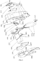
- Fig. 5 is a schematically exploded view of all components of the anti-theft lock 30.
- the anti-theft lock 30 comprises: a case constituted of a face case 3091 and a bottom case 3092; a battery compartment housing constituted of an upper battery compartment cover 3101 and a lower battery compartment cover 3102; a battery 3081 accommodated in the battery compartment housing; a PCB 311 accommodated in the battery compartment housing and integrated with the above-described CPU module 301, the signal receiving/sending module 302, the clock module 303, the vibration sensor module 305, the sound alarm module 3061, and a part of the lock control module 307 (a motor driver not shown in Fig.
- a tongue 3071 thereon; a tongue 3071; a spring 3078 connected to the tongue 3071; location sensors for a first limit switch 3072A and a second limit switch 3072B distributed on the left side and the right side of the tongue 3071 respectively; a motor assembly constituted of a motor 3077 for supplying power to the tongue 3071 to enable the same to move, a sealing gasket 3076 mounted at the side of an output shaft of the motor 3077, and a motor box 3075 for accommodating the motor 3077 and the sealing gasket 3076; a crank member 3074 which is connected to the output shaft of the motor 3077 and rotates together with the same; a tension spring 3073A and a lock pin 3073B which are accommodated in the C-shaped lock groove 312 formed in the lower portion of the case; a lock pin handle 3079 connected to the lock pin 3073B and exposed outside the case; another sealing gasket 3041; a GPS circuit board 3042 integrated with a GPS module and a light alarm module thereon; a GPS protection cover 3043; and
- Fig. 6 is a schematically perspective view of a shape and structure of a battery compartment housing 310 according to an embodiment of the present embodiment.
- the battery compartment housing 310 is formed by joining the upper battery compartment cover 3101 and the lower battery compartment cover 3102 via a bolt, and a sealing ring 3103 (referring to Fig. 5 ) is arranged along the circumference of the joining portion, so that a waterproof and dustproof closed space is formed internally as a battery compartment for accommodating the battery 3081 and the PCB 311.
- the upper battery compartment cover 3101 and the lower battery compartment cover 3102 may also be jointed through clamping, bonding, riveting or the like.
- the battery compartment housing 310 is mounted in a space between the lock mounting hole 3094 and the C-shaped lock groove 312 in the case 309 in the up-down direction, and forms concave portions corresponding to the lock mounting hole 3094 and the C-shaped lock groove 312 respectively in position in a way of bypassing the lock mounting hole 3094 and the C-shaped lock groove 312 (referring to Fig. 7 ).
- the thickness of the battery compartment housing 310 is inconsistent, and the battery compartment housing comprises a thin housing portion with a smaller thickness and a thick housing portion with a larger thickness. An inner space of the thin housing portion is relatively shallower, and an inner space of the thick housing portion is relatively deeper; and the transition between the thin housing portion and the thick housing portion is stepped.
- a wire outlet hole 3107 allowing a power supply wire to pass through is further formed in the thin housing portion of the battery compartment housing 310.
- a wire of the PCB 311 is led out from the wire outlet hole 3107 to be connected to a motor and a location sensor described later so as to supply electric power to them and send and receive control signals.
- the wire outlet hole 3107 is formed in the thin housing portion of the upper battery compartment cover 3101, and a motor assembly and the location sensor of the lock control module described later are arranged at the thin housing portion of the upper battery compartment cover 3101, the wire outlet hole, the motor assembly and the location sensor are made closer in arrangement, reducing the length of the wire, and further compacting the layout of the components.
- wire inlet holes 3108 (referring to Fig.
- the anti-theft lock can be mounted on a frame tube of a bicycle in a sleeving manner via the lock mounting hole, after a wire leading hole opposite to the wire inlet holes 3108 of the anti-theft lock is drilled at a corresponding position of the frame tube, wires can be hidden inside the frame tube to realize wiring, and thus are prevented from being destroyed easily, greatly improving the safety of the anti-theft lock.
- a slot 3105 is arranged at upper middle portions of the inner sides of the left and right side walls of the battery compartment housing 310, and the PCB 311 is inserted in the slot 3105 in a manner that a normal of the PCB is substantially parallel to the front surface of the lock.
- the change of the width of the PCB 311 in the front-rear direction corresponds to that of the thickness of the battery compartment housing 310; that is, the width of the portion of the PCB 311 located at the thick housing portion in the front-rear direction is relatively larger, while the width of the portion of the PCB located at the thin housing portion in the front-rear direction is relatively smaller.
- the battery 3081 is, for example, a lithium ion battery, and is substantially cuboid-shaped; the largest surface (hereinafter also referred to as the maximum surface) in six surfaces of the cuboid and the surface of the PCB are fixed in the thick housing portion of the battery compartment housing 310 in a manner that the maximum surface is substantially parallel to the surface of the PCB.
- the reduction of the PCB area is limited; and moreover, in order to ensure an adequate battery capacity, the reduction of the battery pack size is also limited. Therefore, if the PCB and the substantially cuboid battery pack are mounted in an anti-theft lock in a manner that the surface of the PCB is parallel to the largest surface of the battery pack, although the overall thickness of the anti-theft lock is unchanged, a front area of the anti-theft lock must be increased.
- a space in the thickness direction of the anti-theft lock is fully utilized, so that the surface of the PCB and the largest surface of the battery are inserted in the space between the C-shaped lock groove 312 and the lock mounting hole 3094 in a manner that the surface of the PCB and the largest surface of the battery are perpendicular to the front of the lock.
- the front area of the lock will not be increased excessively, and the lock looks more beautiful and is easy to mount.
- the battery compartment housing with the thin housing portion and the thick housing portion
- the battery and the main portion of the PCB can be mounted in the thick housing portion as described above, and the mounting space of the battery and the PCB is ensured; and meanwhile, the motor assembly, the tongue, the location sensor and the like described later can be mounted in an outside space of the thin housing portion.
- all of the modules can be compactly arranged in a limited space of the case 309, reducing the overall size of the anti-theft lock.
- a protrusion portion 3107 as shown in Fig. 7 (A) is formed in a side wall portion, corresponding to the window 3093 of the case 309, of the battery compartment housing 310, and is matched with the window 3093 in shape, so the protrusion portion 3107 is tightly embedded in the window 3093.
- the battery compartment housing 310 may be made of a hard metal, a hard plastic, or the like, but at least, the protrusion portion 3107 is made of a hard material that does not substantially affect the signal receiving and sending of the antenna 3021.
- the alarm module 306 comprises a sound alarm module 3061 (e.g., a buzzer and a driver thereof) capable of generating a sound alarm, and a light alarm module (e.g., an LED module and a driver thereof which are not shown in the Figure) capable of emitting a light alarm.
- a sound transmission hole 3104 is formed in the battery compartment housing 310 (it is formed in the lower portion of the lower battery compartment cover 3102 in the present embodiment) and corresponds to the mounting position of the sound alarm module 3061; and a waterproof sound transmission film is adhered to the sound transmission hole, so that not only is transmission of alarm sound free from influence, but also dust, water and the like are prevented from entering into the battery compartment through the sound transmission hole 3104.
- the light alarm module is mounted on the GPS circuit board 3042, is communicably connected to the CPU module 301 through a pin 3044 arranged on the GPS circuit board 3042 described later, and is capable of emitting the light alarm under the control of the CPU module 301.
- a light guide hole 3043 (referring to Fig. 4 ) is formed in a GPS protection cover 3043 described later, and a light guide post 3063 is exposed out of the GPS protection cover 3043 from the light guide hole 3105 (referring to Fig. 3 (A) ), so that light emitted from the LED is guided out of the anti-theft lock.
- the length of a path travelled by light which is emitted by the LED and is guided from the inside of the anti-theft lock to the outside is shortened, ensuring the brightness of the light alarm and simplifying a circuit wiring design.
- both the sound alarm module 3061 and the light alarm module are provided; or one of them may be provided as required.
- the anti-theft lock 30 may not be provided with the alarm module 306.
- the signal receiving/sending module 302 is integrated on the PCB 311. Referring to Fig. 5 and 8 , an antenna 3021 is arranged on the PCB 311 and close to the window 303 of the case 309. Therefore, when signal receiving/sending is performed between the antenna and the mobile communication equipment 1 as well as the cloud calculator 2 through a wireless network, poor information receiving/sending caused by a fact that the signal is shielded or blocked by the case 309 or the battery compartment housing 310 is avoided.
- a GPS module is adopted as the positioning module 304.
- the GPS protection cover 3043 is in a form of a trapezoid stage with oblique sides.
- the GPS protection cover attached with a sealing gasket 3041 is buckled at a positioning module mounting portion at the front surface side of the face case 3091, and is fixed to the face case 3091 via clamping, bonding, bolting, riveting or the like.
- the GPS protection cover is made of a hard material (which cannot be easily damaged) which does not substantially affect the receiving of a GPS signal.
- the GPS circuit board 3042 is sealed in a closed space surrounded by the GPS protection cover 3043 and the sealing gasket 3041 in a waterproof and dustproof manner, so that it is ensured that the GPS signal can be received, and the GPS circuit board 3042 is protected from damage.
- a pin 3044 of the GPS circuit board 3042 passes through pin through holes 3106 (referring to Fig. 5 and Fig. 7 (A) ) formed in corresponding positions of the sealing gasket 3041, the face case 3091 and the battery compartment housing 309 (particularly, the upper battery compartment cover 3101) to be inserted into a connector arranged on the PCB 311, so that the GPS module and the light alarm module which are located on the GPS circuit board can communicate with the CPU module 301 on the PCB 311.
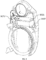
- Fig. 7 is a schematic view of an internal structure of the anti-theft lock 30 according to the embodiment of the present embodiment, wherein (A) is a front view of the anti-theft lock after removing the face case 3091, the sealing gasket 3041, the GPS circuit board 3042 and the GPS protection cover 3043, and (B) is a rear view of the anti-theft lock after removing the bottom case 3092.
- Fig. 8 is a front view the anti-theft lock after removing the face case 3091, the upper battery compartment cover3101, the sealing gasket 3041, the GPS circuit board 3042 and the GPS protection cover 3043 when viewed from the front right side.
- a mechanical part of the anti-theft lock comprises a lock pin provided with a retaining groove and configured to open or close a lock opening through movement thereof to enable the lock to be unlocked or locked, a tongue configured to stop or release movement of the lock pin by entering or exiting from the retaining groove of the lock pin, a first force application member for endowing the lock pin with a force allowing the same to move in the locking direction, and a second force application member for endowing the tongue with a force allowing the same to move in the direction of entering the retaining groove of the lock pin.
- the lock control module comprises: a motor driver configured to receive an instruction signal from a CPU module to control the rotation of an output shaft of a motor assembly; the motor assembly configured to enable the output shaft to rotate according to a driving signal from a motor driver; the output shaft connected to the motor assembly; a tongue driving member configured to convert a rotational driving force of the motor assembly into a driving force allowing the tongue to move out of the retaining groove of the lock pin ; and a location sensor configured to detect the location of the tongue and output a signal indicating the location of the tongue to the CPU module.
- the anti-theft lock 30 is horseshoe-shaped; and the locking pin 3073B is annular, and moves along an annular lock groove 312 formed in the case 309 to open or close the lock opening so as to enable the lock to be unlocked or locked.
- the tongue 3071 is configured to stop or release the movement of the lock pin 3073B along the C-shaped lock groove 312 by entering or exiting from the retaining groove of the lock pin 3073B.
- a driving hole allowing a convex handle of the crank member 3074 to extend into is formed in the middle of the tongue 3071.
- the first force application member is a tension spring 3073A whose one end is fixed in the lock groove 312 and the other end thereof is connected to a non-lock opening end of the lock pin 3073B, and is configured to endow the lock pin 3073B with a force to pull the lock pin towards the unlocking direction.
- the first force application member adopts a spring whose one end is fixed in the lock groove 312 and the other end thereof endows the lock pin 3073B with an elastic force to cause the same to move in the locking direction. That is, during locking, a lock opening end of the lock pin 3073B closes the lock opening and compresses the spring, and the spring generates a force to rebound the lock pin.
- this function may be achieved via other manners.
- the motor assembly comprises a motor 3077 for supplying a power source to the tongue 3071 to allow the same to move, a sealing gasket 3076 mounted at the output shaft side of the motor 3077, and a motor box 3077 for accommodating the motor 3077 and the sealing gasket 3076 inside the motor box 3075.
- the motor assembly is driven by a motor driver (not shown in the Figure) mounted on the PCB 311 to enable the output shaft to rotate.
- the tongue driving member may be of a crank structure.
- one end of the crank member 3074 is connected to the output shaft of the motor assembly, and the other end thereof is provided with the convex handle inserted into the driving hole formed in the tongue.
- the convex handle is driven to rotate along a circular trace using an eccentric distance as the radius.
- the tongue driving member is not limited to the crank structure of the present embodiment, may be of any structure as long as it can convert a rotational driving force of the motor assembly into a driving force allowing the tongue to move out of the retaining groove of the lock pin, or may adopt any transmission mode, such as a worm structure or the like.
- the driving hole is formed in the tongue 3071 as described above, and a stopper is formed in the driving hole.
- the driving hole is formed to realize the following unlocking and locking processes.
- the convex handle of the crank member When the tongue 3071 is in the retaining groove of the lock pin, the convex handle of the crank member is in a standby state at a non-stopper position in the driving hole.
- the convex handle of the crank member When the lock is to be opened, the convex handle of the crank member is rotated to the stopper position in the driving hole and is stopped by the stopper, and the convex handle continues to rotate against the stopper, so that the tongue 3071 is driven to move in the direction of moving out of the retaining groove, and the spring 3078 which endows the tongue 3071 with the force to allow the same to enter the retaining groove of the lock pin 3073B is compressed.
- the tongue 3071 loses a force allowing it to move out of the retaining groove, so the tongue moves in a direction of entering the retaining groove of the lock pin under the force of the spring 3078 till it is propped against the lock pin.
- the lock pin is already in the unlocked state under the action of the tension spring 3073A, and the retaining groove is moved to a position not corresponding to the tongue, so the tongue is propped against the non-retaining groove part of the locking pin; and at the time, the convex handle of the crank member is rotated to a first position in a standby state.
- the retaining groove is moved to the position corresponding to the tongue 3071 along with the movement of the lock pin 3073B, and the tongue 3071 enters the retaining groove under the thrust of the spring 3078 to stop the movement of the lock pin 3073B, so that the locking process is completed.
- the driving hole may take any of various shapes.
- the driving hole is substantially b-shaped, and the top of the right semicircle of the b-shaped driving hole corresponds to the stopper.
- the middle position of a connection portion between the right semicircle of the b-shaped driving hole and a vertical line serves as the first position, and the convex handle is in a standby state at this position (hereinafter also referred to as the first position).
- the convex handle drives the tongue to move upwards (in a direction of moving out of the retaining groove) while being propped against the stopper; when the convex handle reaches a threshold position (hereinafter also referred to as a second position) where it will bypass the stopper, the tongue reaches the maximum position in an upward moving direction (the direction of moving out of the retaining groove), then the convex handle bypasses the stopper to enter a vertical portion of the b-shaped driving hole, and the tongue loses a force for propping it upwards, so that the tongue moves downwards (in a direction of entering the retaining groove) under the thrust of the spring 3078 to be propped against the lock pin; and here, the convex handle stops rotating or moves to the first position so as to be in standby state.
- a threshold position hereinafter also referred to as a second position
- Fig. 9 shows schematic views of exemplary shapes of a driving hole.
- the b-shaped driving hole may be in a shape of an approximately three-quarter circle as shown in Fig. 9 (A) , or an approximately three-quarter prolate ellipse as shown in Fig. 9 (B) as long as the diameter of the circle or minor axis of the prolate ellipse is not less than the diameter of the circular rotation trace of the convex handle.
- a protrusion arranging in the approximate circle as shown in Fig. 9 (C) may serve as the stopper. Therefore, the shapes of the driving hole are various, and the driving hole in any shape may be available as long as it can cooperate with the crank member to realize the above unlocking and locking processes.
- location sensors 3072 for detecting the location of the tongue 3071 comprise a first limit switch 3072A and a second limit switch 3072B located at the left and right sides of the tongue 3071, respectively.
- the two limit switches may be implemented through pressure sensors.
- a first limit piece 3071A and a second limit piece 3071B are arranged at both sides of the tongue 3071 along its moving direction, and located at staggered positions.
- the first limit switch 3072A and the second limit switch 3072B are arranged at positions corresponding to the first limit piece 3071A and the second limit piece 3071B, respectively.
- the first limit piece 3071A When the tongue 3071 enters the retaining groove in the lock pin 3073B, the first limit piece 3071A is propped against the first limit switch 3072A to trigger the first limit switch 3072A to generate a first limit signal to be reported to the CPU module 301.
- the CPU module 301 is informed that the anti-theft lock is in the locking state currently; and here, the second limit piece 3071B is separated from the second limit switch 3072B, so the second limit piece will not trigger the second limit switch to generate a limit signal.
- the CPU module 301 instructs the motor driver to drive the motor assembly to rotate; the tongue 3071 is driven by the crank member to move out of the retaining groove; here, the two limit pieces move along with the movement of the tongue, and the first limit piece 3071A is separated from the first limit switch 3072A; and when the tongue 3071 continues to move to reach or approach the maximum movement distance point, the second limit piece 3071B is propped against the second limit switch 3072B to trigger the same to generate a second limit signal to be reported to the CPU module 301.
- the CPU module 301 is informed that the anti-theft lock is in the locking state currently, and instructs the motor driver to stop driving the motor.
- the convex handle connected to the output shaft of the motor, of the crank member stops moving in the inertia effect after reaching the second position.
- the CPU module 301 may instruct the motor driver to drive the motor to rotate continuously for a preset time period, so that the convex handle can be rotated back to the first position.
- the combination of the pressure sensors and the limit pieces on the tongue is taken as an example to illustrate the detection of the unlocking and locking states, but the present invention is not limited thereto. It is also possible to realize the detection of the unlocking and locking states by various manners, for example, by a combination of laser sensors and location markers on the tongue, or by arranging a distance measurement sensor in the moving direction of the tongue to measure a distance between the tongue and the distance measurement sensor to trigger a location detection signal.
- the anti-theft lock provided by an embodiment of this disclosure is illustrated by taking a horseshoe-shaped lock for a bicycle as an example, but obviously, the form of the anti-theft lock is not limited to the horseshoe-shaped lock, and may be any lock which is provided with a lock opening and a lock pin and capable of realizing locking and unlocking by moving the lock pin to close or open the lock opening.
- the anti-theft lock can be used not only for bicycles but also for any object which needs to be locked.
- the computer program products may comprise computer-readable storage media storing computer-readable programs and instructions for causing processors to realize the respective aspects of this invention.
- the computer-readable storage medium may be a physical device that may maintain and store instructions used by an instruction-executable device.
- the computer-readable storage medium may be, but is not limited to, an electric storage device, a magnetic storage device, an optical storage device, an electromagnetic storage device, a semiconductor storage device, or any suitable combination thereof.
- the computer-readable storage medium includes a portable computer disk, a hard disk, a random access memory (RAM), a read-only memory (ROM), an erasable programmable read-only memory (EPROM or a flash memory), a static random access memory (SRAM), a portable compact disk read-only memory (CD-ROM), a digital versatile disc (DVD), a memory stick, a floppy disk, a mechanical encoding device, a punched card or a groove bulged structure that stores instructions thereon, and any suitable combination thereof.
- RAM random access memory
- ROM read-only memory
- EPROM or a flash memory erasable programmable read-only memory
- SRAM static random access memory
- CD-ROM compact disk read-only memory
- DVD digital versatile disc
- memory stick a floppy disk
- mechanical encoding device a punched card or a groove bulged structure that stores instructions thereon, and any suitable combination thereof.
- the computer-readable storage medium used herein is not interpreted as an instantaneous signal, such as radio waves or other freely propagated electromagnetic waves, electromagnetic waves propagated through a waveguide or other transmission media (e.g., optical pulses of optical fiber cables), or electrical signals transmitted by wires.
- the computer-readable program instructions described herein may be downloaded from a computer-readable storage medium to respective computing/processing devices or downloaded to an external computer or external storage device via a network, such as the Internet, a local area network, a wide area network and/or a wireless network.
- the network may include copper transmission cables, optical fiber transmission, wireless transmission, a router, a firewall, a switch, a gateway computer and/or an edge server.
- a network adapter card or network interface in each computing/processing device receives computer-readable program instructions from the network and forwards the computer-readable program instructions to be stored in the computer-readable storage medium in each computing/processing device.
- the computer-readable program instructions for executing the operations of the present invention may be assembly instructions, instruction set architecture (ISA) instructions, machine instructions, machine-related instructions, microcodes, firmware instructions, state setting data, or source codes or object codes written by any combination of one or more programming languages.
- the programming languages include object-oriented programming languages, such as Smalltalk, C++ and the like, as well as conventional procedural programming languages, such as "C" language or similar programming languages.
- the computer-readable program instructions may be completely executed on a user's computer, partially executed on the user's computer, executed as a separate software package, executed on the user's computer and a remote computer, or completely executed on the remote computer or a server.
- the remote computer may be connected to a user computer via any kind of network, including a local area network (LAN) or a wide area network (WAN), or may be connected to an external computer (e.g., via the Internet provided by an Internet service provider).
- LAN local area network
- WAN wide area network
- an electronic circuit such as a programmable logic circuit, a field programmable gate array (FPGA) or a programmable logic array (PLA) is customized in a personalized manner by utilizing state information of the computer-readable program instructions.
- the electronic circuit may execute the computer-readable program instructions, implementing various aspects of the present invention.
- These computer-readable program instructions may be provided to a processor of a general purpose computer, a special purpose computer, or other programmable data processing devices to generate a machine, so that when these instructions are executed by the processor of the computer or the other programmable data processing devices, a device for realizing functions/actions designated in the flow charts and/or in one or more blocks in the block diagrams.
- These computer-readable program instructions may also be stored in a computer-readable storage medium that causes the computer, the programmable data processing device and/or other devices to operate in a particular manner.
- the computer-readable medium stored with the instructions includes a manufacture that includes instructions for realizing functions/actions designated in the flow charts and/or in one or more blocks in the block diagrams.
- These computer program instructions may further be loaded into a computer or other programmable data processing devices or other devices, such that a series of operating steps may be performed on the computer or other programmable data processing devices or other devices, so as to generate processes realized by the computer, and functions/actions for realizing the functions designated in one or more processes in the flowcharts and/or in one or more blocks in the block diagrams may be provided by the instructions executed on the computer or other programmable data processing devices or other devices.
- each block in the flowcharts and block views may represent one module, one program segment or a part of instructions, which comprise(s) one or more executable instructions for realizing predetermined logical functions.
- the function described in one block may be realized in a sequence difference from that described in the drawings. For example, two consecutive blocks may be executed substantially in parallel, and may be executed in an inverse sequence, depending on the related functions.
- each block or a combination of the blocks in the flowcharts and/or block views may be realized by specific software systems for executing predetermined functions or operations, or by a combination of specific hardware and computer instructions.
- Those skilled in the art should well know that the realization manners by hardware, or software or a combination thereof are all equivalents.
Landscapes
- Engineering & Computer Science (AREA)
- Mechanical Engineering (AREA)
- Physics & Mathematics (AREA)
- General Physics & Mathematics (AREA)
- Radar, Positioning & Navigation (AREA)
- Remote Sensing (AREA)
- Burglar Alarm Systems (AREA)
Abstract
Description
- The present invention relates to the field of bicycle management, and more particularly, to a bicycle anti-theft system, an anti-theft lock and a bicycle with the anti-theft lock.
- China is a big country in producing and using bicycles which always serve as main transportation tools for people travelling a short distance in a city. Due to advantages of a low price, a light weight, energy saving and environmental friendliness of the bicycles, especially with deepening ideas of green tourism, environmental protection and the like in recent years, more and more people start to choose green travel manners, such as bicycle riding. However, when riding bicycles, users have to face the problem of bicycle theft. At present, although there are many types of anti-theft devices on the market, such as mechanical locks, electronic locks and the like, anti-theft effects thereof are unsatisfactory in general. Thieves can unlock or directly damage the locks only with a very short time, or some even steal bicycles with the locks. As a result, this problem not only brings property loss to the users, but also causes great inconvenience.
- Therefore, there is a pressing need to provide a more efficient and more user-friendly bicycle anti-theft system and anti-theft lock as well as a bicycle with the anti-theft lock.
- The present invention is directed to the above problems. An embodiment of this disclosure provides an anti-theft monitoring equipment, comprising: a CPU module for controlling an action of each module in the anti-theft equipment; a clock module for providing time information to the CPU module; a positioning module for providing positioning information to the CPU module; a vibration sensor module for providing a vibration detection signal to the CPU module when detecting a vibration; a lock control module for monitoring and reporting locking state information to the CPU module, and controlling a lock to be unlocked according to an instruction from the CPU module; a memory for storing the time information provided by the clock module to the CPU module and the positioning information provided by the positioning module to the CPU module; a signal receiving/sending module which may be connected to a wireless network to receive information from external equipment and to provide the information to the CPU module, and sends the time information and the positioning information to the external equipment under the control of the CPU module; and a power supply module for supplying power to each module.
- In addition, another embodiment of this disclosure further provides an anti-theft monitoring method using the anti-theft monitoring equipment. The anti-theft monitoring method comprises the following steps: step 1: awakening the CPU module according to a predetermined awakening period, and acquiring the locking state information from the lock control module;
step 2, when the locking state information acquired instep 1 indicates that the lock is in the unlocked state, activating a first sleep mode by the CPU module to instruct the signal receiving/sending module, the clock module, the positioning module and the lock control module to enter a sleep state, enabling the CUP module to enter the sleep state and ignore or shield a vibration detection signal sent from the vibration sensor module, waiting for a next awakening period, and repeatingstep 1;step 3, when the locking state information acquired instep 1 indicates that the lock is in the locked state, activating a second sleep mode by the CPU module to instruct the signal receiving/sending module, the clock module, the positioning module and the lock control module to enter the sleep state, and enabling the CUP module to enter the sleep state but not ignore or shield the vibration detection signal sent from the vibration sensor module; step 4, when the vibration sensor module detects a vibration under the second sleep mode, sending by the vibration sensor module a vibration detection signal to the CUP module, awakening the CPU module based on the vibration detection signal, collecting by the CPU module vibration intensity information included in the vibration detection signal, and determining by the CPU module whether the vibration intensity exceeds a preset threshold value or not; step 5, when the vibration intensity collected in step 4 does not exceed the preset threshold value, enabling the CPU module to return to the second sleep mode; step 6, when the vibration intensity collected in step 4 exceeds the preset threshold value, awakening by the CPU module all of the modules, collecting positioning information and time information continuously or intermittently at a preset time interval, and detecting whether it is feasible to communicate with the external equipment through the signal receiving/sending module; step 7, when it is detected that communication is feasible in step 6, sending the collected positioning information and time information to the external equipment through the s signal receiving/sending module; step 8, when it is detected that the communication is infeasible in step 6, storing the collected positioning information and time information in the memory, and detecting whether it is feasible to communicate with the external equipment continuously or intermittently at a preset time interval; and step 9, when it is detected that communication is feasible in step 8, sending the positioning information and the time information stored in the memory to the external equipment through the signal receiving/sending module. - In addition, the embodiment of this disclosure further provides an anti-theft system comprising the anti-theft monitoring equipment as described above and external equipment constituted of mobile communication equipment and /or a cloud calculator.
- In addition, the embodiment of this disclosure further provides a two-wheeler or a tricycle with the anti-theft monitoring equipment and the lock as described above.
- The anti-theft monitoring equipment and the anti-theft monitoring method thereof, and the anti-theft system provided by the embodiment of this disclosure can track a stolen vehicle and manage alarm information, so that the vehicle is effectively prevented from being stolen.
-
-
Fig. 1 is a schematic view of an overall structure of an anti-theft system provided by an embodiment of this disclosure. -
Fig. 2 is a schematic view of functional modules of a bicycle anti-theft lock provided by an embodiment of this disclosure. -
Fig. 3 is a schematic view of an overall appearance of an anti-theft lock, wherein (A) is a front view of the anti-theft lock, and (B) is a rear view of the anti-theft lock. -
Fig.4 is a perspective view of the anti-theft lock. -
Fig. 5 is a schematically exploded view of all components of the anti-theft lock. -
Fig. 6 is a schematically perspective view of a shape and structure of a battery compartment housing of an anti-theft lock according to an embodiment of this disclosure. -
Fig. 7 is a schematic view of an internal structure of the anti-theft lock according to the embodiment of the present embodiment, wherein (A) is a front view of the anti-theft lock after removing a face case, a sealing gasket, a GPS circuit board and a GPS protection cover, and (B) is a rear view of the anti-theft lock after removing a bottom case. -
Fig. 8 is a front view the anti-theft lock after removing the face case, an upper battery compartment cover, the sealing gasket, the GPS circuit board and the GPS protection cover when viewed from the front right side. -
Fig. 9 shows schematic views of shapes of a driving hole, and each of (A)-(C) inFig. 9 illustrates one shape of the driving hole. -
Fig. 10 is a flow chart of implementing the anti-theft system provided by an embodiment of this disclosure. - The embodiments of the present invention will now be described in detail with reference to specific implementations. For clarity, parts or structures known to those skilled in the art are not specifically described herein. In addition, although the embodiments are described with reference to certain examples, it should be understood that such description is not intended to limit the present invention within the described examples. On the contrary, such description is intended to encompass all substitutions, improvements and equivalent solutions within the spirit and scope of the present invention defined in the appended claims.
- Examples of a bicycle anti-theft lock and system are taken to illustrate hereinafter, but of course, the anti-theft lock and the anti-theft system may also be applied to any of two-wheelers and tricycles such as electric bicycles and motorcycles.
-
Fig. 1 is a schematic view of an overall structure of an anti-theft system provided by the an embodiment of this disclosure. As shown inFig. 1 , the system comprisesmobile communication equipment 1, acloud calculator 2 and abicycle 3. Thebicycle 3 comprises ananti-theft lock 30. Themobile communication equipment 1 establishes communication with thecloud calculator 2 via a wireless network; thecloud calculator 2 establishes communication with theanti-theft lock 30 of the bicycle via the wireless network; and thecloud calculator 2 and/or themobile communication equipment 1 receive(s) bicycle state information and the like sent from theanti-theft lock 30 of thebicycle 3 and manage(s) the bicycle. In addition, themobile communication equipment 1 controls theanti-theft lock 30 of thebicycle 3 via thecloud calculator 2, or thecloud calculator 2 directly controls theanti-theft lock 30 of thebicycle 3. - In the present embodiment, the
mobile communication equipment 1 may send or receive a signal via a wired or wireless network or other manners, or may process or store the signal, for example, in a memory in a physical storage state. Each piece of themobile communication equipment 1 may be an electronic device that comprises hardware, software, or an embedded logic component or a combination of two or more such components, and is capable of executing appropriate functions implemented or supported by the mobile communication device. For example, the mobile communication equipment may be a smart phone, a tablet computer, a portable e-mail device, an electronic book, a handheld game machine and/or a game controller, a notebook computer, a netbook, a handheld electronic device, a smart wear device, and the like. The present invention covers any suitable mobile communication equipment. The mobile communication equipment may enable a user using the same to access the network. In particular, the mobile communication equipment may comprise a processing device including an application processing unit and a radio frequency/digital signal processor, a display screen, a mini keyboard that may comprise physical keys, touch keys covering the display screen or a combination thereof, a user identification module card, a memory device that may comprise an ROM, an RAM, a flash memory or any combination thereof, a Wi-Fi and/or Bluetooth interface, a wireless telephone interface, a power supply management circuit with an associated battery, a USB interface and connector, an audio management system with an associated microphone, speaker and headphone jack, and various optional accessories such as a digital camera, a global positioning system and an accelerator. In addition, various client applications may be installed on the mobile communication equipment, and may be configured to allow the use of the mobile communication equipment to transmit commands suitable for operation with other devices. Such applications may be downloaded from a server and installed into the memory of the mobile communication equipment, and may be pre-installed on the mobile communication equipment. In the embodiments of the present invention, themobile communication equipment 1 is provided with a bicycle user terminal application which can assist the user in realizing functions of managing thebicycle 3, wherein the functions include, but are not limited to, theft prevention. In other embodiments of the present invention, themobile communication equipment 1 may also be provided with a maintenance personnel application that may be configured to assist the maintenance personnel in realizing functions of operational management for thebicycle 3, wherein the functions include, but are not limited to, theft prevention, maintenance and the like. According to some embodiments of the present invention, themobile communication equipment 1 can obtain a location of thebicycle 3 by running a bicycle user terminal. Further, if thebicycle 3 is stolen, themobile communication equipment 1 will receive a prompt message from thecloud calculator 2. In addition, the user can remotely unlock thebicycle 3 through themobile communication equipment 1. - In the embodiment of this disclosure, the
cloud calculator 2 is a server. The server in this description should be understood as a service point providing processing, database and communication facilities. For example, the server may be a single physical processor having related communication, data storage and database facilities, or a networked or clustered processor, or a cluster of related networks and storage devices, and can operate software, one or more database systems and application software providing services supported by the server. The servers may vary greatly in configuration or performance, but generally the server may include one or more central processing units and memories. The server further include one or more large-volume storage devices, one or more power sources, one or more wired or wireless network interfaces, one or more input/output interfaces, one or more operating systems such as Windows Server, Mac OS X, Unix, Linux and FreeBSD, and the like. In particular, the cloud calculator may be an integral server or a distributed server across multiple computers or computer data centers. The server may include various servers, such as but not limited to a network server, a news server, a mail server, a message server, an advertisement server, a file server, an application server, an interactive server, a database server or a proxy server. In some embodiments, each server may include hardware, software or an inbuilt logic assembly or two or more of such assemblies used to execute suitable functions supported by the server. In the embodiment of this disclosure, the server is configured to provide all functions necessary to support bicycle management. In the embodiment of this disclosure, the cloud calculator can calculate and determine whether a signal sent by the anti-theft lock is caused by a theft or not. In addition, the cloud calculator may send an instruction to the anti-theft lock to control it to/not to send an alarm; and the cloud calculator may also send an instruction to the anti-theft lock to enable the same 30 to upload state information (e.g., positioning information) of the bicycle periodically or in real time. - In the present invention, the wireless network covers any suitable wireless network, such as but not limited to a 4G network, a 3G network, a GPRS network, a Wi-Fi network or the like. In addition, the wireless network through which the
cloud calculator 2 and themobile communication equipment 1 are coupled together may be the same as or different from the wireless network through which thecloud calculator 2 and thebicycle 3 are coupled together. -
Fig. 2 is a schematic view of functional modules of a bicycleanti-theft lock 30 provided by an embodiment of this disclosure. As shown inFig. 2 , theanti-theft lock 30 comprises aCPU module 301, a signal receiving/sendingmodule 302, aclock module 303, apositioning module 304, avibration sensor module 305, analarm module 306, alock control module 307 and amemory 313 which are communicatively connected to theCPU module 301, respectively, and apower supply module 308 for supplying electric power to the respective modules. - The
CPU module 301 is a central processing unit of theanti-theft lock 30, and is configured to control operations and the like of the respective modules of theanti-theft lock 30, wherein the control refers to, for example, processing an instruction from thecloud calculator 2 and information and the like from the other modules of theanti-theft lock 30, and sending control instructions and the like to other modules. - For example, the signal receiving/sending
module 302 comprises an antenna, a buffer and the like described later, and may be connected to a wireless network to receive/send information from/to external equipment such as themobile communication equipment 1, thecloud calculator 2 and the like under the control of theCPU module 301. - The
clock module 303 provides time information for theCPU module 301, so that theCPU module 301, themobile communication equipment 1 and thecloud calculator 2 can acquire current time information of thebicycle 3. If it is not necessary to acquire the current time information of the bicycle 3 (for example, the time information of the bicycle is based on a lock time of the cloud calculator 2), theclock module 303 may be omitted. However, it is possible that thebicycle 3 may be in a variety of environments. For example, if the communication environment is poor while the bicycle is stolen, although thebicycle 3 may move to a communication environment later and thecloud calculator 2 may determine that the bicycle is stolen according to information sent from theanti-theft lock 30, and the like, the specific time when the bicycle is stolen cannot be acquired. Therefore, preferably, theanti-theft lock 30 is provided with theclock module 303 which can store an actual time in a timely manner when the bicycle is stolen in the memory and send the time to thecloud calculator 2 and/or themobile communication equipment 1 immediately or later, so that an appropriate anti-theft strategy may be taken. Theclock module 303 may also be integrated in theCPU module 301 as required. - For example, the
positioning module 304 may be a GPS module, a Beidou satellite positioning module or the like, and is capable of collecting current location information (hereinafter referred to as positioning information) and reporting the same to theCPU module 301; and under the control of theCPU module 301, the positioning information may be sent to external equipment such as themobile communication equipment 1 and/or thecloud calculator 2 via the signal receiving/sendingmodule 302. - For example, the
vibration sensor module 305 may be one of various sensors for detecting vibration, such as an acceleration sensor, and may be a sensor as long as it is capable of detecting vibration and providing information such as vibration intensity for theCPU module 301, so that it is not limited to the acceleration sensor. - For example, the
alarm module 306 may issue an on-site alarm by issuing a sound and/or light alarm/alarms after receiving an alarm instruction signal from theCPU module 301. It should be noted that as the anti-theft system provided by the embodiment of this disclosure has functions of positioning and tracking a bicycle, thealarm module 306 configured to issue an on-site alarm is not an essential component for the anti-theft system provided by the present invention. - The
lock control module 307 is configured to unlock the lock pin of theanti-theft lock 30 according to an instruction of theCPU module 301, monitor locking state information (a locking state and an unlocking state) of theanti-theft lock 30, and report the information to theCPU module 301. - The
memory 313 is configured to store the time information supplied by theclock module 303 to theCPU module 301 and the positioning information supplied by thepositioning module 301 to theCPU module 304, and may store the vibration intensity information supplied by thevibration sensor module 305 to theCPU module 301 as required. - The
power supply module 308 comprises a battery and the like described later, and can supply electric power to the various electronic modules described above. It should be noted that in embodiments to be described later, thepower supply module 308 may comprise the battery as an electric power storage device; or in a case that the electric power can be supplied from the outside in real time, for example, electric power is generated via solar energy, the battery in the power supply module may be omitted, and the power supply module is implemented via a combination of a photovoltaic element, a capacitor and the like. In addition, inFig. 2 , thepower supply module 308 is electrically connected to theCPU module 301 to supply electric power to the other modules via theCPU module 301, or may be electrically connected to each module directly to supply electric power to the same. - It should be noted that all of the modules shown in
Fig. 2 may be integrated with the lock as a whole like an embodiment described below, or part of the modules, as separate vehicle-mounted electronic equipment (anti-theft monitoring equipment), may be arranged outside the lock as long as required related information receiving and sending among the modules and the lock can be realized through a necessary circuit. For example, except for the motor assembly, the location sensor and the like described later in thelock control module 307, which must be mounted in the anti-theft lock, other components may be arranged outside the lock as the separate vehicle-mounted electronic equipment (anti-theft monitoring equipment). - An anti-theft method of the anti-theft system provided by an embodiment of this disclosure will be described below.
Fig. 10 is a flow chart of the anti-theft method provided by an embodiment of this disclosure. - First, the
CPU module 301 periodically performs self-awakening according to a preset period (S101) and awakes thelock control module 307 to inquire about current state information of the anti-theft lock (S102). - If the
lock control module 307 returns a signal indicating that the anti-theft lock is in the unlocked state ("unlocking" in S103) to theCPU module 301, theCPU module 301 considers that the bicycle is being used normally, so that a first sleep mode is activated to instruct the signal receiving/sendingmodule 302, theclock module 303, thepositioning module 304, thealarm module 306 and thelock control module 307 to enter the sleep state, and the CPU module also enters the sleep mode; and the CPU module ignores or shields a vibration detection signal from the vibration sensor module 305 (S104), and waits for a next awakening period (S101). Therefore, when the bicycle is normally used, electric power can be saved as the modules are in the sleep mode. - If the
lock control module 307 returns a signal indicating that the anti-theft lock is in the locked state ("locking" in S103) to theCPU module 301, theCPU module 301 activates a second sleep mode to instruct the signal receiving/sendingmodule 302, theclock module 303, thepositioning module 304, thealarm module 306 and thelock control module 307 to enter the sleep state, and the CPU module also enters the sleep mode; however, theCPU module 301 does not ignore or shield the vibration detection signal from the vibration sensor module 305 (S106). - In this case, when detecting a vibration ("Yes" in S107), the
vibration sensor module 305 sends the vibration detection signal to theCPU module 301, and theCPU module 301 is awakened based on the vibration detection signal, then acquires vibration intensity information in the vibration detection signal (S108), and determines whether the vibration intensity exceeds a preset threshold value α or not (S109). - If the vibration intensity does not exceed the preset threshold value α, it is considered that the vibration is not caused by a destructive behavior, and may be generated only through occasional slight shaking, so the CPU module returns to the second sleep mode ("Not" in (S109).
- If the vibration intensity exceeds a preset threshold α ("Yes" in S109), it is considered that the vibration is caused by a severe destructive behavior, so the CPU module awakes all the modules, collects positioning information, current time information and the like continuously or intermittently at a preset time interval (S110), and instructs the
alarm module 306 to alarm (S111). Meanwhile, the CPU module detects whether or not it is possible to communicate with external equipment such as thecloud calculator 2 and/or the mobile communication equipment 1 (S 112) via the signal receiving/sendingmodule 302. If it is feasible to communicate ("Yes" in S112), the CPU module reports the collected positioning information and current time information to the external equipment such as thecloud calculator 2 and/or the mobile communication equipment 1 (S113). If it is temporarily infeasible to communicate ("Not" in S112), the CPU module stores the collected positioning information, current time information, and the like in the memory (S 114); and the CPU module detects whether it is feasible to communicate with the external equipment such as thecloud calculator 2 and/or themobile communication equipment 1 continuously or intermittently at a preset time interval (S 112). If it is detected that the communication is feasible ("Yes" in S 112), the stored positioning information and current time information are reported to the external equipment such as thecloud calculator 2 and/or the mobile communication equipment 1 (S113). In addition, in step S110, the vibration intensity information may also be collected continuously; instep S 114, the vibration intensity information may be stored; and in step S113, the collected vibration intensity information may also be reported to the external equipment such as thecloud calculator 2 and/or themobile communication equipment 1. -
Figs. 3-9 show specific embodiments of ananti-theft lock 30. - For facilitating illustration, a state shown in
Fig. 3 (A) is used as a reference. The width direction of theanti-theft lock 30 is defined as a left-right direction, the height direction of theanti-theft lock 30 is defined as an up-down direction, and the thickness direction of theanti-theft lock 30 is defined as a front-rear direction. In addition, sometimes, the surface of the anti-theft lock shown inFig. 3 (A) may be referred to as the front surface or the front, and the surface of the anti-theft lock shown inFig. 3 (B) may be referred to as the back surface or the rear surface. -
Fig. 3 is a schematic view of an overall appearance of ananti-theft lock 30, whereinFig. 3 (A) is a front view of theanti-theft lock 30, andFig. 3 (B) is a rear view of theanti-theft lock 30.Fig.4 is a perspective view of theanti-theft lock 30. - As shown in
Fig. 3 (A) , theanti-theft lock 30 in this embodiment is a horseshoe-shaped lock. Acase 309 of the anti-theft lock is horseshoe-shaped integrally, and comprises a lock body portion and side arm portions extending from left and right sides of the lock body portion respectively to form a substantially C-shaped lock opening. Alock mounting hole 3094 for mounting theanti-theft lock 30 to a bicycle or the like is formed in the center of the top of the lock body portion. For example, through the hole, the anti-theft lock may be fitted over a frame tube of the bicycle. - A positioning module mounting portion is arranged below the
lock mounting hole 3094; and aGPS protection cover 3043 is mounted at the positioning module mounting portion, and theGPS module 3042 and the like described later are accommodated in the GPS protection cover. Referring toFig. 4 , thelock mounting hole 3094, theGPS protection cover 3043 and peripheral portions thereof form a stage in the shape of a trapezoid with oblique sides (hereinafter referred to as a trapezoid stage 3095) whose portions are more protruded forwards than other portions of the front surface of thecase 309 and in which the projection areas in the front surface are gradually reduced. Moreover, according to the design, after mounting, the front surface and side surfaces of theGPS protection cover 3043 are smoothly transitioned with the other portions of thetrapezoid stage 3095. Therefore, after theGPS protection cover 3043 is fixed to thecase 309 as described later, it is not easy to open theGPS protection cover 3043, so that the anti-theft lock is well protected from destroy. In addition, alight guide hole 3105 for exposing alight guide post 3063 described later is formed in a position near the bottom of theGPS protection cover 3043. - Returning to
Fig. 3 (A) , an annular lock portion of the horseshoe-shaped lock is arranged below thetrapezoid stage 3095, and is in a form of a C-shaped opening which opens downwards. Referring toFig. 7 described later, a C-shapedlock groove 312 is formed inside the annular lock portion of the case. In addition, a slide hole for guiding alock pin handle 3079 to slide is further formed in one side arm of the annular lock portion. - Moreover, referring to
Fig. 5 , awindow 3093 is formed in the side wall of one side (the right side in this embodiment) in the left-right direction of aface case 3091. In order to improve the destruction resistance of theanti-theft lock 30, preferably, thecase 309 of theanti-theft lock 30 may be made of a metal material such as stainless steel. As the metal case will shield or overly block radio signal receiving and sending of the signal receiving/sending module 302 (an antenna 3021) accommodated in the case, thewindow 3093 is formed to reduce the influence of thecase 309 on signal receiving and receiving of theantenna 3021. - In addition, as shown in
Fig. 3 (B) , asound alarm hole 3096 is formed in the back surface of thecase 309, and corresponds to asound transmission hole 3104 in thebattery compartment housing 310 described later. -
Fig. 5 is a schematically exploded view of all components of theanti-theft lock 30. As shown inFig. 5 , the anti-theft lock 30 comprises: a case constituted of a face case 3091 and a bottom case 3092; a battery compartment housing constituted of an upper battery compartment cover 3101 and a lower battery compartment cover 3102; a battery 3081 accommodated in the battery compartment housing; a PCB 311 accommodated in the battery compartment housing and integrated with the above-described CPU module 301, the signal receiving/sending module 302, the clock module 303, the vibration sensor module 305, the sound alarm module 3061, and a part of the lock control module 307 (a motor driver not shown inFig. 5 ) thereon; a tongue 3071; a spring 3078 connected to the tongue 3071; location sensors for a first limit switch 3072A and a second limit switch 3072B distributed on the left side and the right side of the tongue 3071 respectively; a motor assembly constituted of a motor 3077 for supplying power to the tongue 3071 to enable the same to move, a sealing gasket 3076 mounted at the side of an output shaft of the motor 3077, and a motor box 3075 for accommodating the motor 3077 and the sealing gasket 3076; a crank member 3074 which is connected to the output shaft of the motor 3077 and rotates together with the same; a tension spring 3073A and a lock pin 3073B which are accommodated in the C-shaped lock groove 312 formed in the lower portion of the case; a lock pin handle 3079 connected to the lock pin 3073B and exposed outside the case; another sealing gasket 3041; a GPS circuit board 3042 integrated with a GPS module and a light alarm module thereon; a GPS protection cover 3043; and a light guide post 3063. -
Fig. 6 is a schematically perspective view of a shape and structure of abattery compartment housing 310 according to an embodiment of the present embodiment. As shown inFig. 6 , thebattery compartment housing 310 is formed by joining the upperbattery compartment cover 3101 and the lowerbattery compartment cover 3102 via a bolt, and a sealing ring 3103 (referring toFig. 5 ) is arranged along the circumference of the joining portion, so that a waterproof and dustproof closed space is formed internally as a battery compartment for accommodating thebattery 3081 and thePCB 311. Of course, the upperbattery compartment cover 3101 and the lowerbattery compartment cover 3102 may also be jointed through clamping, bonding, riveting or the like. - In the present embodiment, the
battery compartment housing 310 is mounted in a space between thelock mounting hole 3094 and the C-shapedlock groove 312 in thecase 309 in the up-down direction, and forms concave portions corresponding to thelock mounting hole 3094 and the C-shapedlock groove 312 respectively in position in a way of bypassing thelock mounting hole 3094 and the C-shaped lock groove 312 (referring toFig. 7 ). As shown inFig. 6 , the thickness of thebattery compartment housing 310 is inconsistent, and the battery compartment housing comprises a thin housing portion with a smaller thickness and a thick housing portion with a larger thickness. An inner space of the thin housing portion is relatively shallower, and an inner space of the thick housing portion is relatively deeper; and the transition between the thin housing portion and the thick housing portion is stepped. - In addition, a
wire outlet hole 3107 allowing a power supply wire to pass through is further formed in the thin housing portion of thebattery compartment housing 310. A wire of thePCB 311 is led out from thewire outlet hole 3107 to be connected to a motor and a location sensor described later so as to supply electric power to them and send and receive control signals. As thewire outlet hole 3107 is formed in the thin housing portion of the upperbattery compartment cover 3101, and a motor assembly and the location sensor of the lock control module described later are arranged at the thin housing portion of the upperbattery compartment cover 3101, the wire outlet hole, the motor assembly and the location sensor are made closer in arrangement, reducing the length of the wire, and further compacting the layout of the components. In addition, wire inlet holes 3108 (referring toFig. 5 ) are formed in the case 309 (the bottom case 3092) and the battery compartment housing 310 (the lower battery compartment cover 3102) and correspond to the lock mounting hole in position. Through the wire inlet holes, a power supply wire and the like used in charging of, for example, abattery 3081 can be led into the battery compartment from the outside of the case. Because the anti-theft lock can be mounted on a frame tube of a bicycle in a sleeving manner via the lock mounting hole, after a wire leading hole opposite to thewire inlet holes 3108 of the anti-theft lock is drilled at a corresponding position of the frame tube, wires can be hidden inside the frame tube to realize wiring, and thus are prevented from being destroyed easily, greatly improving the safety of the anti-theft lock. - Referring to
Fig. 5 andFig. 7 (B) , aslot 3105 is arranged at upper middle portions of the inner sides of the left and right side walls of thebattery compartment housing 310, and thePCB 311 is inserted in theslot 3105 in a manner that a normal of the PCB is substantially parallel to the front surface of the lock. Moreover, the change of the width of thePCB 311 in the front-rear direction corresponds to that of the thickness of thebattery compartment housing 310; that is, the width of the portion of thePCB 311 located at the thick housing portion in the front-rear direction is relatively larger, while the width of the portion of the PCB located at the thin housing portion in the front-rear direction is relatively smaller. In addition, in this embodiment, thebattery 3081 is, for example, a lithium ion battery, and is substantially cuboid-shaped; the largest surface (hereinafter also referred to as the maximum surface) in six surfaces of the cuboid and the surface of the PCB are fixed in the thick housing portion of thebattery compartment housing 310 in a manner that the maximum surface is substantially parallel to the surface of the PCB. - Generally, in order to ensure that the PCB has an enough space to mount all of the modules, the reduction of the PCB area is limited; and moreover, in order to ensure an adequate battery capacity, the reduction of the battery pack size is also limited. Therefore, if the PCB and the substantially cuboid battery pack are mounted in an anti-theft lock in a manner that the surface of the PCB is parallel to the largest surface of the battery pack, although the overall thickness of the anti-theft lock is unchanged, a front area of the anti-theft lock must be increased. In a case that a lock front area occupied by the C-shaped
lock groove 312 and thelock mounting hole 3094 is not reduced, requirements on the mounting of the PCB and the battery pack can be met only by increasing an area in the height direction (up-down direction) or the width direction (left-right direction) of the lock. As a result, the anti-theft lock looks huge, affecting the beauty and possibly the mounting of the anti-theft lock. In an embodiment of this disclosure, a space in the thickness direction of the anti-theft lock is fully utilized, so that the surface of the PCB and the largest surface of the battery are inserted in the space between the C-shapedlock groove 312 and thelock mounting hole 3094 in a manner that the surface of the PCB and the largest surface of the battery are perpendicular to the front of the lock. In this way, the front area of the lock will not be increased excessively, and the lock looks more beautiful and is easy to mount. - In addition, by providing the battery compartment housing with the thin housing portion and the thick housing portion, the battery and the main portion of the PCB can be mounted in the thick housing portion as described above, and the mounting space of the battery and the PCB is ensured; and meanwhile, the motor assembly, the tongue, the location sensor and the like described later can be mounted in an outside space of the thin housing portion. Thus, all of the modules can be compactly arranged in a limited space of the
case 309, reducing the overall size of the anti-theft lock. - In addition, a
protrusion portion 3107 as shown inFig. 7 (A) is formed in a side wall portion, corresponding to thewindow 3093 of thecase 309, of thebattery compartment housing 310, and is matched with thewindow 3093 in shape, so theprotrusion portion 3107 is tightly embedded in thewindow 3093. In order to ensure the overall strength and the like, thebattery compartment housing 310 may be made of a hard metal, a hard plastic, or the like, but at least, theprotrusion portion 3107 is made of a hard material that does not substantially affect the signal receiving and sending of theantenna 3021. - Referring to
Fig. 5 , in the present embodiment, thealarm module 306 comprises a sound alarm module 3061 (e.g., a buzzer and a driver thereof) capable of generating a sound alarm, and a light alarm module (e.g., an LED module and a driver thereof which are not shown in the Figure) capable of emitting a light alarm. Asound transmission hole 3104 is formed in the battery compartment housing 310 (it is formed in the lower portion of the lowerbattery compartment cover 3102 in the present embodiment) and corresponds to the mounting position of thesound alarm module 3061; and a waterproof sound transmission film is adhered to the sound transmission hole, so that not only is transmission of alarm sound free from influence, but also dust, water and the like are prevented from entering into the battery compartment through thesound transmission hole 3104. - In addition, the light alarm module is mounted on the
GPS circuit board 3042, is communicably connected to theCPU module 301 through apin 3044 arranged on theGPS circuit board 3042 described later, and is capable of emitting the light alarm under the control of theCPU module 301. Moreover, a light guide hole 3043 (referring toFig. 4 ) is formed in aGPS protection cover 3043 described later, and alight guide post 3063 is exposed out of theGPS protection cover 3043 from the light guide hole 3105 (referring toFig. 3 (A) ), so that light emitted from the LED is guided out of the anti-theft lock. - By arranging the light alarm module on the GPS circuit board near the outer surface of the anti-theft lock, the length of a path travelled by light which is emitted by the LED and is guided from the inside of the anti-theft lock to the outside is shortened, ensuring the brightness of the light alarm and simplifying a circuit wiring design.
- It should be noted that in the present embodiment, both the
sound alarm module 3061 and the light alarm module are provided; or one of them may be provided as required. Alternatively, as the anti-theft system of the embodiment has other anti-theft strategies as described above, theanti-theft lock 30 may not be provided with thealarm module 306. - The signal receiving/sending
module 302 is integrated on thePCB 311. Referring toFig. 5 and8 , anantenna 3021 is arranged on thePCB 311 and close to thewindow 303 of thecase 309. Therefore, when signal receiving/sending is performed between the antenna and themobile communication equipment 1 as well as thecloud calculator 2 through a wireless network, poor information receiving/sending caused by a fact that the signal is shielded or blocked by thecase 309 or thebattery compartment housing 310 is avoided. - In the present embodiment, a GPS module is adopted as the
positioning module 304. Referring toFig. 5 , as described above, theGPS protection cover 3043 is in a form of a trapezoid stage with oblique sides. After theGPS circuit board 3042 is accommodated inside the GPS protection cover, the GPS protection cover attached with a sealinggasket 3041 is buckled at a positioning module mounting portion at the front surface side of theface case 3091, and is fixed to theface case 3091 via clamping, bonding, bolting, riveting or the like. Preferably, the GPS protection cover is made of a hard material (which cannot be easily damaged) which does not substantially affect the receiving of a GPS signal. Therefore, theGPS circuit board 3042 is sealed in a closed space surrounded by theGPS protection cover 3043 and the sealinggasket 3041 in a waterproof and dustproof manner, so that it is ensured that the GPS signal can be received, and theGPS circuit board 3042 is protected from damage. In addition, apin 3044 of theGPS circuit board 3042 passes through pin through holes 3106 (referring toFig. 5 andFig. 7 (A) ) formed in corresponding positions of the sealinggasket 3041, theface case 3091 and the battery compartment housing 309 (particularly, the upper battery compartment cover 3101) to be inserted into a connector arranged on thePCB 311, so that the GPS module and the light alarm module which are located on the GPS circuit board can communicate with theCPU module 301 on thePCB 311. -
Fig. 7 is a schematic view of an internal structure of theanti-theft lock 30 according to the embodiment of the present embodiment, wherein (A) is a front view of the anti-theft lock after removing theface case 3091, the sealinggasket 3041, theGPS circuit board 3042 and theGPS protection cover 3043, and (B) is a rear view of the anti-theft lock after removing thebottom case 3092.Fig. 8 is a front view the anti-theft lock after removing theface case 3091, the upper battery compartment cover3101, the sealinggasket 3041, theGPS circuit board 3042 and theGPS protection cover 3043 when viewed from the front right side. - A mechanical part of the anti-theft lock provided by an embodiment of this disclosure comprises a lock pin provided with a retaining groove and configured to open or close a lock opening through movement thereof to enable the lock to be unlocked or locked, a tongue configured to stop or release movement of the lock pin by entering or exiting from the retaining groove of the lock pin, a first force application member for endowing the lock pin with a force allowing the same to move in the locking direction, and a second force application member for endowing the tongue with a force allowing the same to move in the direction of entering the retaining groove of the lock pin.
- The lock control module comprises: a motor driver configured to receive an instruction signal from a CPU module to control the rotation of an output shaft of a motor assembly; the motor assembly configured to enable the output shaft to rotate according to a driving signal from a motor driver; the output shaft connected to the motor assembly; a tongue driving member configured to convert a rotational driving force of the motor assembly into a driving force allowing the tongue to move out of the retaining groove of the lock pin ; and a location sensor configured to detect the location of the tongue and output a signal indicating the location of the tongue to the CPU module.
- Particularly, in this embodiment, the
anti-theft lock 30 is horseshoe-shaped; and thelocking pin 3073B is annular, and moves along anannular lock groove 312 formed in thecase 309 to open or close the lock opening so as to enable the lock to be unlocked or locked. - The
tongue 3071 is configured to stop or release the movement of thelock pin 3073B along the C-shapedlock groove 312 by entering or exiting from the retaining groove of thelock pin 3073B. Referring toFig. 8 , a driving hole allowing a convex handle of thecrank member 3074 to extend into is formed in the middle of thetongue 3071. - In this embodiment, the first force application member is a
tension spring 3073A whose one end is fixed in thelock groove 312 and the other end thereof is connected to a non-lock opening end of thelock pin 3073B, and is configured to endow thelock pin 3073B with a force to pull the lock pin towards the unlocking direction. Of course, in a variation embodiment, for example, the first force application member adopts a spring whose one end is fixed in thelock groove 312 and the other end thereof endows thelock pin 3073B with an elastic force to cause the same to move in the locking direction. That is, during locking, a lock opening end of thelock pin 3073B closes the lock opening and compresses the spring, and the spring generates a force to rebound the lock pin. Thus, when the tongue moves out of the retaining groove, the force of the spring is released to eject the lock pin, so that the lock opening is opened. Besides, this function may be achieved via other manners. - In addition, referring to
Fig. 5 , in this embodiment, the motor assembly comprises amotor 3077 for supplying a power source to thetongue 3071 to allow the same to move, a sealinggasket 3076 mounted at the output shaft side of themotor 3077, and amotor box 3077 for accommodating themotor 3077 and the sealinggasket 3076 inside themotor box 3075. By providing the sealinggasket 3077 and themotor box 3075 with respect to themotor 3077, the dustproof and waterproof motor assembly can be formed to improve the environmental resistance of the anti-theft lock. The motor assembly is driven by a motor driver (not shown in the Figure) mounted on thePCB 311 to enable the output shaft to rotate. - In an embodiment of this disclosure, the tongue driving member may be of a crank structure. Referring to
Fig. 5 , one end of thecrank member 3074 is connected to the output shaft of the motor assembly, and the other end thereof is provided with the convex handle inserted into the driving hole formed in the tongue. When the output shaft of the motor assembly rotates, the convex handle is driven to rotate along a circular trace using an eccentric distance as the radius. In addition, of course, the tongue driving member is not limited to the crank structure of the present embodiment, may be of any structure as long as it can convert a rotational driving force of the motor assembly into a driving force allowing the tongue to move out of the retaining groove of the lock pin, or may adopt any transmission mode, such as a worm structure or the like. - The driving hole is formed in the
tongue 3071 as described above, and a stopper is formed in the driving hole. The driving hole is formed to realize the following unlocking and locking processes. - When the
tongue 3071 is in the retaining groove of the lock pin, the convex handle of the crank member is in a standby state at a non-stopper position in the driving hole. When the lock is to be opened, the convex handle of the crank member is rotated to the stopper position in the driving hole and is stopped by the stopper, and the convex handle continues to rotate against the stopper, so that thetongue 3071 is driven to move in the direction of moving out of the retaining groove, and thespring 3078 which endows thetongue 3071 with the force to allow the same to enter the retaining groove of thelock pin 3073B is compressed. When the convex handle continues to rotate and then bypasses the stopper, thetongue 3071 loses a force allowing it to move out of the retaining groove, so the tongue moves in a direction of entering the retaining groove of the lock pin under the force of thespring 3078 till it is propped against the lock pin. Here, the lock pin is already in the unlocked state under the action of thetension spring 3073A, and the retaining groove is moved to a position not corresponding to the tongue, so the tongue is propped against the non-retaining groove part of the locking pin; and at the time, the convex handle of the crank member is rotated to a first position in a standby state. - When the latch pin 3073 is pulled to the locking direction, the retaining groove is moved to the position corresponding to the
tongue 3071 along with the movement of thelock pin 3073B, and thetongue 3071 enters the retaining groove under the thrust of thespring 3078 to stop the movement of thelock pin 3073B, so that the locking process is completed. - To achieve the above processes, the driving hole may take any of various shapes. For example, in the present embodiment, the driving hole is substantially b-shaped, and the top of the right semicircle of the b-shaped driving hole corresponds to the stopper. For example, the middle position of a connection portion between the right semicircle of the b-shaped driving hole and a vertical line serves as the first position, and the convex handle is in a standby state at this position (hereinafter also referred to as the first position). In the unlocking process, when rotating anticlockwise to the top (the stopper) along the right semicircle of the b-shaped driving hole from the bottom up, the convex handle drives the tongue to move upwards (in a direction of moving out of the retaining groove) while being propped against the stopper; when the convex handle reaches a threshold position (hereinafter also referred to as a second position) where it will bypass the stopper, the tongue reaches the maximum position in an upward moving direction (the direction of moving out of the retaining groove), then the convex handle bypasses the stopper to enter a vertical portion of the b-shaped driving hole, and the tongue loses a force for propping it upwards, so that the tongue moves downwards (in a direction of entering the retaining groove) under the thrust of the
spring 3078 to be propped against the lock pin; and here, the convex handle stops rotating or moves to the first position so as to be in standby state. -
Fig. 9 shows schematic views of exemplary shapes of a driving hole. The b-shaped driving hole may be in a shape of an approximately three-quarter circle as shown inFig. 9 (A) , or an approximately three-quarter prolate ellipse as shown inFig. 9 (B) as long as the diameter of the circle or minor axis of the prolate ellipse is not less than the diameter of the circular rotation trace of the convex handle. In addition, instead of using the b-shaped driving hole, a protrusion arranging in the approximate circle as shown inFig. 9 (C) may serve as the stopper. Therefore, the shapes of the driving hole are various, and the driving hole in any shape may be available as long as it can cooperate with the crank member to realize the above unlocking and locking processes. - In addition, in the present embodiment, location sensors 3072 for detecting the location of the
tongue 3071 comprise afirst limit switch 3072A and asecond limit switch 3072B located at the left and right sides of thetongue 3071, respectively. The two limit switches may be implemented through pressure sensors. Particularly, referring toFig. 7 (A) , afirst limit piece 3071A and asecond limit piece 3071B are arranged at both sides of thetongue 3071 along its moving direction, and located at staggered positions. Thefirst limit switch 3072A and thesecond limit switch 3072B are arranged at positions corresponding to thefirst limit piece 3071A and thesecond limit piece 3071B, respectively. When thetongue 3071 enters the retaining groove in thelock pin 3073B, thefirst limit piece 3071A is propped against thefirst limit switch 3072A to trigger thefirst limit switch 3072A to generate a first limit signal to be reported to theCPU module 301. Thus, theCPU module 301 is informed that the anti-theft lock is in the locking state currently; and here, thesecond limit piece 3071B is separated from thesecond limit switch 3072B, so the second limit piece will not trigger the second limit switch to generate a limit signal. - When unlocking is required, the
CPU module 301 instructs the motor driver to drive the motor assembly to rotate; thetongue 3071 is driven by the crank member to move out of the retaining groove; here, the two limit pieces move along with the movement of the tongue, and thefirst limit piece 3071A is separated from thefirst limit switch 3072A; and when thetongue 3071 continues to move to reach or approach the maximum movement distance point, thesecond limit piece 3071B is propped against thesecond limit switch 3072B to trigger the same to generate a second limit signal to be reported to theCPU module 301. Thus, theCPU module 301 is informed that the anti-theft lock is in the locking state currently, and instructs the motor driver to stop driving the motor. Here, the convex handle, connected to the output shaft of the motor, of the crank member stops moving in the inertia effect after reaching the second position. Alternatively, after receiving the second limit signal, theCPU module 301 may instruct the motor driver to drive the motor to rotate continuously for a preset time period, so that the convex handle can be rotated back to the first position. - In the above embodiment, the combination of the pressure sensors and the limit pieces on the tongue is taken as an example to illustrate the detection of the unlocking and locking states, but the present invention is not limited thereto. It is also possible to realize the detection of the unlocking and locking states by various manners, for example, by a combination of laser sensors and location markers on the tongue, or by arranging a distance measurement sensor in the moving direction of the tongue to measure a distance between the tongue and the distance measurement sensor to trigger a location detection signal.
- The anti-theft lock provided by an embodiment of this disclosure is illustrated by taking a horseshoe-shaped lock for a bicycle as an example, but obviously, the form of the anti-theft lock is not limited to the horseshoe-shaped lock, and may be any lock which is provided with a lock opening and a lock pin and capable of realizing locking and unlocking by moving the lock pin to close or open the lock opening. Of course, the anti-theft lock can be used not only for bicycles but also for any object which needs to be locked.
- Those skilled in the art shall well know that, as electronic and information technologies such as large scale integrated circuit technologies develop and the trend that software are realized by hardware advances, it becomes difficult to distinguish software and hardware of computer systems, since any operation or execution of any instruction can be realized by software or hardware. Whether to realize a function of a machine using a software or hardware solution may depend on non-technical factors such as prices, speeds, reliability, storage capacity, change period etc. Therefore, a more direct and clear description manner of a technical solution to a person skilled in the fields of electronic and information technologies may be descriptions of the operations of the solution. When knowing the operations to be performed, those skilled in the art may directly design desired products based on considerations of the non-technical factors.
- This invention may be realized through systems, methods and/or computer program products. The computer program products may comprise computer-readable storage media storing computer-readable programs and instructions for causing processors to realize the respective aspects of this invention.
- The computer-readable storage medium may be a physical device that may maintain and store instructions used by an instruction-executable device. For example, the computer-readable storage medium may be, but is not limited to, an electric storage device, a magnetic storage device, an optical storage device, an electromagnetic storage device, a semiconductor storage device, or any suitable combination thereof. More specific examples (non-exhaustive lists) of the computer-readable storage medium include a portable computer disk, a hard disk, a random access memory (RAM), a read-only memory (ROM), an erasable programmable read-only memory (EPROM or a flash memory), a static random access memory (SRAM), a portable compact disk read-only memory (CD-ROM), a digital versatile disc (DVD), a memory stick, a floppy disk, a mechanical encoding device, a punched card or a groove bulged structure that stores instructions thereon, and any suitable combination thereof. The computer-readable storage medium used herein is not interpreted as an instantaneous signal, such as radio waves or other freely propagated electromagnetic waves, electromagnetic waves propagated through a waveguide or other transmission media (e.g., optical pulses of optical fiber cables), or electrical signals transmitted by wires.
- The computer-readable program instructions described herein may be downloaded from a computer-readable storage medium to respective computing/processing devices or downloaded to an external computer or external storage device via a network, such as the Internet, a local area network, a wide area network and/or a wireless network. The network may include copper transmission cables, optical fiber transmission, wireless transmission, a router, a firewall, a switch, a gateway computer and/or an edge server. A network adapter card or network interface in each computing/processing device receives computer-readable program instructions from the network and forwards the computer-readable program instructions to be stored in the computer-readable storage medium in each computing/processing device.
- The computer-readable program instructions for executing the operations of the present invention may be assembly instructions, instruction set architecture (ISA) instructions, machine instructions, machine-related instructions, microcodes, firmware instructions, state setting data, or source codes or object codes written by any combination of one or more programming languages. The programming languages include object-oriented programming languages, such as Smalltalk, C++ and the like, as well as conventional procedural programming languages, such as "C" language or similar programming languages. The computer-readable program instructions may be completely executed on a user's computer, partially executed on the user's computer, executed as a separate software package, executed on the user's computer and a remote computer, or completely executed on the remote computer or a server. When the remote computer is referred to, the remote computer may be connected to a user computer via any kind of network, including a local area network (LAN) or a wide area network (WAN), or may be connected to an external computer (e.g., via the Internet provided by an Internet service provider). In some embodiments, an electronic circuit, such as a programmable logic circuit, a field programmable gate array (FPGA) or a programmable logic array (PLA) is customized in a personalized manner by utilizing state information of the computer-readable program instructions. The electronic circuit may execute the computer-readable program instructions, implementing various aspects of the present invention.
- Various aspects of the present invention are described herein with reference to flow charts and/or block diagrams of the method, device (system) and computer program product according to the embodiments of the present invention. It should be understood that flow charts and/or each block in the block diagrams, as well as the flow charts and/or the combinations of all blocks in the block diagrams, may be implemented by computer-readable program instructions.
- These computer-readable program instructions may be provided to a processor of a general purpose computer, a special purpose computer, or other programmable data processing devices to generate a machine, so that when these instructions are executed by the processor of the computer or the other programmable data processing devices, a device for realizing functions/actions designated in the flow charts and/or in one or more blocks in the block diagrams. These computer-readable program instructions may also be stored in a computer-readable storage medium that causes the computer, the programmable data processing device and/or other devices to operate in a particular manner. Thus, the computer-readable medium stored with the instructions includes a manufacture that includes instructions for realizing functions/actions designated in the flow charts and/or in one or more blocks in the block diagrams.
- These computer program instructions may further be loaded into a computer or other programmable data processing devices or other devices, such that a series of operating steps may be performed on the computer or other programmable data processing devices or other devices, so as to generate processes realized by the computer, and functions/actions for realizing the functions designated in one or more processes in the flowcharts and/or in one or more blocks in the block diagrams may be provided by the instructions executed on the computer or other programmable data processing devices or other devices.
- The flowcharts and block views in the accompanying drawings show the structures, functions and operations that may be realized by the systems, methods and computer program products of this invention. Each block in the flowcharts and block views may represent one module, one program segment or a part of instructions, which comprise(s) one or more executable instructions for realizing predetermined logical functions. It should also be noted that in some alternative implementations, the function described in one block may be realized in a sequence difference from that described in the drawings. For example, two consecutive blocks may be executed substantially in parallel, and may be executed in an inverse sequence, depending on the related functions. It should be noted that each block or a combination of the blocks in the flowcharts and/or block views may be realized by specific software systems for executing predetermined functions or operations, or by a combination of specific hardware and computer instructions. Those skilled in the art should well know that the realization manners by hardware, or software or a combination thereof are all equivalents.
Claims (10)
- An Anti-theft monitoring equipment mounted on an anti-theft object, the anti-theft monitoring equipment comprising:a CPU module configured to control an action of each module in the anti-theft equipment;a clock module configured to provide time information to the CPU module;a positioning module configured to provide positioning information to the CPU module;a vibration sensor module configured to provide a vibration detection signal including vibration intensity information to the CPU module when detecting a vibration;a lock control module configured to monitor and report locking state information of a lock for locking the anti-theft object to the CPU module, and control the lock to be unlocked according to an instruction from the CPU module, the locking state information indicating whether the lock is in an locked state or an unlocked state;a memory configured to store the time information provided by the clock module to the CPU module and the positioning information provided by the positioning module to the CPU module;a signal receiving/sending module which is capable of being connected to a wireless network to receive information from external equipment and to provide the information to the CPU module, and sending the time information and the positioning information to the external equipment under the control of the CPU module; anda power supply module configured to supply power to each module.
- The anti-theft monitoring equipment of claim 1, further comprising:an alarm module configured to issue an alarm at least through a sound alarm and/or a light alarm after receiving an alarm instruction signal from the CPU module.
- The anti-theft monitoring equipment of claim 1, wherein
the memory also stores the vibration intensity information provided by the vibration sensor module to the CPU module; and
the signal receiving/sending module also sends the vibration intensity information to the external equipment. - The anti-theft monitoring equipment of claim 1, wherein
the lock control module comprises:a motor;a motor driver for receiving an instruction signal from the CPU module to drive an output shaft of the motor to rotate;a tongue driving member connected to the output shaft of the motor and configured to convert a rotational driving force of the motor into a driving force allowing a tongue to move out of a retaining groove of a lock pin; anda location sensor configured to detect the location of the tongue of a lock and determine the locking state information based on whether the tongue is located in the retaining groove of the lock pin. - The anti-theft monitoring equipment of any of claims 1-4, wherein
the anti-theft monitoring equipment and the lock are integrated. - An anti-theft monitoring method using the anti-theft monitoring equipment of claim 1, the method comprising the following steps:step 1, awakening the CPU module according to a predetermined awakening period, and acquiring the locking state information from the lock control module;step 2, when the locking state information acquired in step 1 indicates that the lock is in the unlocked state, activating a first sleep mode by the CPU module to instruct the signal receiving/sending module, the clock module, the positioning module and the lock control module to enter a sleep state, enabling the CUP module to enter the sleep state and ignore or shield a vibration detection signal sent from the vibration sensor module, waiting for a next awakening period, and repeating step 1;step 3, when the locking state information acquired in step 1 indicates that the lock is in the locked state, activating a second sleep mode by the CPU module to instruct the signal receiving/sending module, the clock module, the positioning module and the lock control module to enter the sleep state, and enabling the CUP module to enter the sleep state but not ignore or shield the vibration detection signal sent from the vibration sensor module;step 4, when the vibration sensor module detects a vibration under the second sleep mode, sending by the vibration sensor module a vibration detection signal to the CUP module, awakening the CPU module based on the vibration detection signal, collecting by the CPU module vibration intensity information included in the vibration detection signal, and determining by the CPU module whether the vibration intensity exceeds a preset threshold value or not;step 5, when the vibration intensity collected in step 4 does not exceed the preset threshold value, enabling the CPU module to return to the second sleep mode;step 6, when the vibration intensity collected in step 4 exceeds the preset threshold value, awakening by the CPU module all of the modules, collecting positioning information and time information continuously or intermittently at a preset time interval, and detecting whether it is feasible to communicate with the external equipment through the signal receiving/sending module;step 7, when it is detected that communication is feasible in step 6, sending the collected positioning information and time information to the external equipment through the signal receiving/sending module;step 8, when it is detected that the communication is infeasible in step 6, storing the collected positioning information and time information in the memory, and detecting whether it is feasible to communicate with the external equipment continuously or intermittently at a preset time interval; andstep 9, when it is detected that the communication is feasible in step 8, sending the positioning information and the time information stored in the memory to the external equipment through the signal receiving/sending module.
- The anti-theft monitoring method of claim 6, wherein
in step 6, vibration intensity information is also collected; in step 8, the collected vibration intensity information is also stored in the memory; and in step 9, the collected vibration intensity information is also sent to the external equipment. - An anti-theft system, comprising:the anti-theft monitoring equipment of any of claims 1-4, andexternal equipment constituted of mobile communication equipment and/or a cloud calculator.
- The anti-theft system of claim 8, wherein the anti-theft monitoring equipment executes the anti-theft monitoring method of claim of 6 or 7.
- A two-wheeler or a tricycle, comprising the anti-theft monitoring equipment of any of claims 1-4 and the lock.
Applications Claiming Priority (2)
| Application Number | Priority Date | Filing Date | Title |
|---|---|---|---|
| CN201510886398.8A CN105480329B (en) | 2015-12-06 | 2015-12-06 | Anti-theft monitoring equipment and monitoring method, the burglary-resisting system of two wheeler or tricycle |
| PCT/CN2016/106131 WO2017097096A1 (en) | 2015-12-06 | 2016-11-16 | Anti-theft monitoring device, monitoring method and anti-theft system for two-wheeler or three-wheeler |
Publications (3)
| Publication Number | Publication Date |
|---|---|
| EP3263431A1 true EP3263431A1 (en) | 2018-01-03 |
| EP3263431A4 EP3263431A4 (en) | 2018-06-13 |
| EP3263431B1 EP3263431B1 (en) | 2020-01-08 |
Family
ID=55667694
Family Applications (1)
| Application Number | Title | Priority Date | Filing Date |
|---|---|---|---|
| EP16872288.2A Active EP3263431B1 (en) | 2015-12-06 | 2016-11-16 | Anti-theft monitoring device, monitoring method and anti-theft system for two-wheeler or three-wheeler |
Country Status (4)
| Country | Link |
|---|---|
| US (1) | US10220899B2 (en) |
| EP (1) | EP3263431B1 (en) |
| CN (1) | CN105480329B (en) |
| WO (1) | WO2017097096A1 (en) |
Families Citing this family (43)
| Publication number | Priority date | Publication date | Assignee | Title |
|---|---|---|---|---|
| CN107035238B (en) | 2015-12-06 | 2018-06-19 | 北京摩拜科技有限公司 | Theftproof lock |
| CN105460105B (en) * | 2015-12-06 | 2018-09-11 | 北京摩拜科技有限公司 | A kind of lock |
| CN105480329B (en) | 2015-12-06 | 2017-12-29 | 北京摩拜科技有限公司 | Anti-theft monitoring equipment and monitoring method, the burglary-resisting system of two wheeler or tricycle |
| US10142196B1 (en) * | 2016-04-15 | 2018-11-27 | Senseware, Inc. | System, method, and apparatus for bridge interface communication |
| CN106080855B (en) * | 2016-05-27 | 2019-02-01 | 北京奇虎科技有限公司 | The safety monitoring method and device of electric bicycle |
| CN106347529A (en) * | 2016-09-12 | 2017-01-25 | 北海和思科技有限公司 | Internet of things bicycle anti-theft system |
| CN107422356A (en) * | 2016-10-09 | 2017-12-01 | 北京摩拜科技有限公司 | Vehicle positioning method and Vehicle positioning system |
| CN106741332A (en) * | 2016-12-28 | 2017-05-31 | 北京拜克洛克科技有限公司 | Intelligent bicycle lock and intelligent bicycle |
| CN106600795A (en) * | 2017-01-10 | 2017-04-26 | 深圳市为控科技有限公司 | Bicycle and tricycle and anti-theft lockset and anti-theft system used by bicycle and tricycle |
| CN106840274A (en) * | 2017-04-23 | 2017-06-13 | 福建强闽信息科技有限公司 | A kind of online water monitoring device and its application method based on LTE_Cat M1 |
| CN107516379B (en) * | 2017-07-13 | 2020-07-24 | 深圳市盛路物联通讯技术有限公司 | Data processing method and device |
| DE102017116941A1 (en) * | 2017-07-26 | 2019-01-31 | ABUS August Bremicker Söhne Kommanditgesellschaft | Electronic bicycle lock |
| CN107380305A (en) * | 2017-07-27 | 2017-11-24 | 上海传英信息技术有限公司 | A kind of anti-theft method for bicycle and theft-proof device for bicycle based on smart machine |
| CN107358705A (en) * | 2017-08-25 | 2017-11-17 | 苏州市千尺浪信息技术服务有限公司 | A kind of burglary-resisting system of Intelligent Office space |
| CN107394861B (en) * | 2017-09-06 | 2024-03-05 | 广东绿网新能源科技有限公司 | Charging plug position monitoring device and energy storage control method based on same |
| CN108678564B (en) * | 2018-04-27 | 2020-04-03 | 浙江大华技术股份有限公司 | Awakening method and device of intelligent lock |
| CN109094517B (en) * | 2018-07-06 | 2021-05-07 | 广西科技大学 | Automobile network anti-theft alarm method and alarm system |
| TWM567725U (en) * | 2018-07-18 | 2018-10-01 | 源文興工業股份有限公司 | Senseable lock structure of bicycle |
| CN109094689B (en) * | 2018-08-31 | 2021-01-19 | 京东方科技集团股份有限公司 | Vehicle for public rental |
| CN110969728B (en) * | 2018-09-30 | 2021-04-23 | 北京骑胜科技有限公司 | A vehicle lock control method and device, and a computer-readable storage medium |
| TWM580534U (en) * | 2019-01-10 | 2019-07-11 | 源文興工業股份有限公司 | Control device interconnecting electric bicycle and electronic lock |
| US12037817B2 (en) * | 2019-05-15 | 2024-07-16 | Rad Power Bikes Inc. | Bicycle security devices and system |
| CN110730436A (en) * | 2019-10-21 | 2020-01-24 | 佛山华科芯软科技有限公司 | Locator with lock car function |
| CN111031501A (en) * | 2019-11-15 | 2020-04-17 | 国网安徽省电力有限公司安庆供电公司 | Mobile terminal management method, mobile terminal and management system |
| CN110949315A (en) * | 2019-12-01 | 2020-04-03 | 苏州易换骑网络科技有限公司 | Anti-dismantling system for vehicle body battery |
| CN111275859A (en) * | 2020-01-23 | 2020-06-12 | 摩拜(北京)信息技术有限公司 | Control method of shared moped and shared moped |
| CN113404389A (en) * | 2020-03-16 | 2021-09-17 | 上海钧正网络科技有限公司 | Locking and unlocking method of vehicle and lock body device |
| GB2594510B (en) * | 2020-04-30 | 2022-05-18 | Lockheed Tech Ltd | Information processing device |
| CN111605646A (en) * | 2020-05-08 | 2020-09-01 | 上海摩融信息科技有限公司 | Electric vehicle alarm, electric vehicle monitoring system, method, monitoring platform and electric vehicle |
| CN112435422B (en) * | 2020-12-07 | 2024-05-17 | 格力博(江苏)股份有限公司 | Anti-theft alarm method and system for electric tool and electric tool |
| TWI738559B (en) * | 2020-11-09 | 2021-09-01 | 美商糖果屋研發有限公司 | Lock |
| US12246791B2 (en) * | 2021-04-02 | 2025-03-11 | Shimano Inc. | Bicycle part and method of forming bicycle part |
| CN112857561B (en) * | 2020-12-31 | 2023-06-13 | 重庆国际复合材料股份有限公司 | Intelligent tray |
| CN112721859B (en) * | 2021-01-14 | 2022-08-19 | 广州橙行智动汽车科技有限公司 | Vehicle control method and device, vehicle and medium |
| CN112415899A (en) * | 2021-01-25 | 2021-02-26 | 南京航空航天大学 | Real-time active vibration reduction system and vibration reduction method based on compact RIO |
| US12015434B2 (en) * | 2021-03-29 | 2024-06-18 | Rad Power Bikes Inc. | Security systems and communication networks for electric bicycles |
| CN113501067B (en) * | 2021-07-09 | 2023-06-20 | 上海锐承通讯技术有限公司 | Unlocking method for electric vehicle and electric vehicle |
| USD964843S1 (en) * | 2021-10-28 | 2022-09-27 | Shenzhen Omni Intelligent Technology Co,. Ltd | Electronic horseshoe lock |
| CN114858269A (en) * | 2022-04-06 | 2022-08-05 | 联合汽车电子有限公司 | Equipment monitoring method, device, medium, sensor, controller and vehicle |
| CN116238456A (en) * | 2023-03-20 | 2023-06-09 | 中国第一汽车股份有限公司 | Method and device for determining disassembly state of power battery, vehicle and storage medium |
| CN116394878A (en) * | 2023-05-23 | 2023-07-07 | 成都赛力斯科技有限公司 | Car locking method and device, electronic equipment and readable storage medium |
| US12428871B2 (en) * | 2023-07-12 | 2025-09-30 | Robert Kapp | NFC driven disc lock |
| CN119527228B (en) * | 2024-12-04 | 2025-08-15 | 深圳欧米智能科技有限公司 | Abnormal locking prevention hub lock control method and device |
Family Cites Families (26)
| Publication number | Priority date | Publication date | Assignee | Title |
|---|---|---|---|---|
| US5416464A (en) * | 1993-04-22 | 1995-05-16 | Winner International Royalty Corporation | Vehicle anti-theft alarm system |
| JP3699208B2 (en) * | 1996-07-17 | 2005-09-28 | 本田技研工業株式会社 | Vehicle antitheft device |
| CN2383163Y (en) * | 1999-08-30 | 2000-06-14 | 马如飞 | Multiple dimension identifying motor vehicle anti-theft detector |
| FR2842493B1 (en) * | 2002-07-18 | 2005-09-09 | De Meder Laurent Bourgine | METHOD AND DEVICE FOR SECURITY FOR VEHICLE TWO WHEELS AND THE LIKE |
| ITMI20040335A1 (en) * | 2004-02-25 | 2004-05-25 | Tavola Spa | METHOD AND DEVICES TO REPORT A VEHICLE THEFT ATTEMPT ALSO INDICATING THE POSITION |
| US20060288744A1 (en) * | 2005-06-28 | 2006-12-28 | William Smith | Alarm lock |
| JP2008037377A (en) * | 2006-08-10 | 2008-02-21 | Matsushita Electric Ind Co Ltd | Bicycle lock device, bicycle, and electric bicycle |
| CN201525437U (en) * | 2009-09-11 | 2010-07-14 | 车晓明 | Voice buzzing remote control burglar alarm of battery box |
| WO2011145074A1 (en) * | 2010-05-19 | 2011-11-24 | Microio - Serviços De Electrónica Lda. | System for managing the shared use of bicycles |
| US20130150028A1 (en) * | 2011-12-12 | 2013-06-13 | Biketrak, Inc. | Bicycle theft monitoring and recovery devices |
| US9013301B2 (en) * | 2012-07-02 | 2015-04-21 | Donald S. Williams | Mobile lock with retractable cable |
| WO2014012564A1 (en) * | 2012-07-20 | 2014-01-23 | Velolock Ltd. | Locking device for a bicycle |
| US9260885B2 (en) * | 2012-10-19 | 2016-02-16 | Brian Asquith | Theft deterrent lock |
| GB2511099A (en) * | 2013-02-22 | 2014-08-27 | Scorpion Automotive Ltd | Power saving vehicle tracking |
| CN104670367A (en) * | 2013-12-02 | 2015-06-03 | 南京物联传感技术有限公司 | Anti-theft early warning device and anti-theft early warning method |
| US9157742B1 (en) * | 2014-01-16 | 2015-10-13 | WI-MM Corporation | Cloud based activity monitor for bicycles and application |
| CN204775605U (en) * | 2015-03-26 | 2015-11-18 | 苏州大学 | Lock control system and contain intelligent lock of this system based on virtual key |
| CN204631965U (en) * | 2015-05-21 | 2015-09-09 | 张鑫 | Vehicle lock controller and bicycle theft-prevention control system |
| CN104973169B (en) * | 2015-07-13 | 2017-09-12 | 吴俊斌 | A kind of anti-theft device for intelligent bicycle |
| CN105480329B (en) * | 2015-12-06 | 2017-12-29 | 北京摩拜科技有限公司 | Anti-theft monitoring equipment and monitoring method, the burglary-resisting system of two wheeler or tricycle |
| CN205345142U (en) * | 2015-12-06 | 2016-06-29 | 北京摩拜科技有限公司 | Pickproof lock and printed circuit board subassembly, bicycle anti -theft system , bicycle thereof |
| CN205417866U (en) * | 2015-12-06 | 2016-08-03 | 北京摩拜科技有限公司 | Two wheeler, tricycle and theftproof monitoring facilities , anti -theft system that use thereof |
| CN205311745U (en) * | 2015-12-06 | 2016-06-15 | 北京摩拜科技有限公司 | Horse's hoof type lock |
| CN205311744U (en) * | 2015-12-06 | 2016-06-15 | 北京摩拜科技有限公司 | Bicycle of this lock is locked and installed |
| CN107035238B (en) * | 2015-12-06 | 2018-06-19 | 北京摩拜科技有限公司 | Theftproof lock |
| CN105460105B (en) * | 2015-12-06 | 2018-09-11 | 北京摩拜科技有限公司 | A kind of lock |
-
2015
- 2015-12-06 CN CN201510886398.8A patent/CN105480329B/en active Active
-
2016
- 2016-11-16 EP EP16872288.2A patent/EP3263431B1/en active Active
- 2016-11-16 WO PCT/CN2016/106131 patent/WO2017097096A1/en not_active Ceased
-
2017
- 2017-09-27 US US15/717,557 patent/US10220899B2/en active Active
Also Published As
| Publication number | Publication date |
|---|---|
| CN105480329B (en) | 2017-12-29 |
| US20180015974A1 (en) | 2018-01-18 |
| EP3263431A4 (en) | 2018-06-13 |
| EP3263431B1 (en) | 2020-01-08 |
| HK1223342A1 (en) | 2017-07-28 |
| CN105480329A (en) | 2016-04-13 |
| US10220899B2 (en) | 2019-03-05 |
| WO2017097096A1 (en) | 2017-06-15 |
Similar Documents
| Publication | Publication Date | Title |
|---|---|---|
| EP3263431B1 (en) | Anti-theft monitoring device, monitoring method and anti-theft system for two-wheeler or three-wheeler | |
| US10370869B2 (en) | Horseshoe-shaped lock | |
| CN205417866U (en) | Two wheeler, tricycle and theftproof monitoring facilities , anti -theft system that use thereof | |
| CN105460105B (en) | A kind of lock | |
| CN205311744U (en) | Bicycle of this lock is locked and installed | |
| CN205311745U (en) | Horse's hoof type lock | |
| US10538285B2 (en) | Handlebar locking mechanism, handlebar locking device, and moving body | |
| WO2016180075A1 (en) | Remote detection method and system for smart electric vehicle and code table of system | |
| US10501137B2 (en) | Handlebar lock system | |
| CN201080214Y (en) | Electric vehicle with intelligent theft-proof lock | |
| CN212434515U (en) | Central control equipment and electric bicycles | |
| CN106812390B (en) | Intelligent lock | |
| CN210437295U (en) | A intelligent communication box and vehicle using motor for vehicle using motor | |
| CN107054514B (en) | Rotary shaft rotation limiting device, Vehicular turn limit system, device, control method | |
| US12162551B1 (en) | Bicycle with security features | |
| US11345423B2 (en) | Data collection device with removable battery pack | |
| HK1223343B (en) | A horseshoe lock | |
| CN205788356U (en) | Mobile terminal tricycle antitheft security system based on APP platform | |
| HK1223342B (en) | Anti-theft monitoring equipment and monitoring method, anti-theft system for two-wheeled or three-wheeled vehicles | |
| CN109720449B (en) | Direction lock, control system for direction lock and bicycle | |
| CN205059818U (en) | Bicycle GPS tracking system in seat post clamp | |
| CN219759831U (en) | Battery compartment structure and vehicle-mounted mobile measurement system | |
| Fernandez et al. | U-Loq Design Specifications | |
| CN206107409U (en) | Public bicycle system with GPS positioning function |
Legal Events
| Date | Code | Title | Description |
|---|---|---|---|
| STAA | Information on the status of an ep patent application or granted ep patent |
Free format text: STATUS: THE INTERNATIONAL PUBLICATION HAS BEEN MADE |
|
| PUAI | Public reference made under article 153(3) epc to a published international application that has entered the european phase |
Free format text: ORIGINAL CODE: 0009012 |
|
| STAA | Information on the status of an ep patent application or granted ep patent |
Free format text: STATUS: REQUEST FOR EXAMINATION WAS MADE |
|
| 17P | Request for examination filed |
Effective date: 20170927 |
|
| AK | Designated contracting states |
Kind code of ref document: A1 Designated state(s): AL AT BE BG CH CY CZ DE DK EE ES FI FR GB GR HR HU IE IS IT LI LT LU LV MC MK MT NL NO PL PT RO RS SE SI SK SM TR |
|
| AX | Request for extension of the european patent |
Extension state: BA ME |
|
| A4 | Supplementary search report drawn up and despatched |
Effective date: 20180511 |
|
| RIC1 | Information provided on ipc code assigned before grant |
Ipc: G07F 17/00 20060101ALI20180504BHEP Ipc: B60R 25/20 20130101ALI20180504BHEP Ipc: B60R 25/10 20130101ALI20180504BHEP Ipc: B62H 5/20 20060101AFI20180504BHEP Ipc: B62H 5/16 20060101ALI20180504BHEP Ipc: B60R 25/102 20130101ALI20180504BHEP Ipc: B60R 25/34 20130101ALI20180504BHEP |
|
| STAA | Information on the status of an ep patent application or granted ep patent |
Free format text: STATUS: EXAMINATION IS IN PROGRESS |
|
| 17Q | First examination report despatched |
Effective date: 20180803 |
|
| DAV | Request for validation of the european patent (deleted) | ||
| DAX | Request for extension of the european patent (deleted) | ||
| GRAP | Despatch of communication of intention to grant a patent |
Free format text: ORIGINAL CODE: EPIDOSNIGR1 |
|
| STAA | Information on the status of an ep patent application or granted ep patent |
Free format text: STATUS: GRANT OF PATENT IS INTENDED |
|
| INTG | Intention to grant announced |
Effective date: 20190703 |
|
| GRAS | Grant fee paid |
Free format text: ORIGINAL CODE: EPIDOSNIGR3 |
|
| GRAA | (expected) grant |
Free format text: ORIGINAL CODE: 0009210 |
|
| STAA | Information on the status of an ep patent application or granted ep patent |
Free format text: STATUS: THE PATENT HAS BEEN GRANTED |
|
| AK | Designated contracting states |
Kind code of ref document: B1 Designated state(s): AL AT BE BG CH CY CZ DE DK EE ES FI FR GB GR HR HU IE IS IT LI LT LU LV MC MK MT NL NO PL PT RO RS SE SI SK SM TR |
|
| REG | Reference to a national code |
Ref country code: GB Ref legal event code: FG4D |
|
| REG | Reference to a national code |
Ref country code: CH Ref legal event code: EP |
|
| REG | Reference to a national code |
Ref country code: DE Ref legal event code: R096 Ref document number: 602016028125 Country of ref document: DE |
|
| REG | Reference to a national code |
Ref country code: IE Ref legal event code: FG4D |
|
| REG | Reference to a national code |
Ref country code: AT Ref legal event code: REF Ref document number: 1222363 Country of ref document: AT Kind code of ref document: T Effective date: 20200215 |
|
| REG | Reference to a national code |
Ref country code: NL Ref legal event code: MP Effective date: 20200108 |
|
| REG | Reference to a national code |
Ref country code: LT Ref legal event code: MG4D |
|
| PG25 | Lapsed in a contracting state [announced via postgrant information from national office to epo] |
Ref country code: NL Free format text: LAPSE BECAUSE OF FAILURE TO SUBMIT A TRANSLATION OF THE DESCRIPTION OR TO PAY THE FEE WITHIN THE PRESCRIBED TIME-LIMIT Effective date: 20200108 Ref country code: RS Free format text: LAPSE BECAUSE OF FAILURE TO SUBMIT A TRANSLATION OF THE DESCRIPTION OR TO PAY THE FEE WITHIN THE PRESCRIBED TIME-LIMIT Effective date: 20200108 Ref country code: LT Free format text: LAPSE BECAUSE OF FAILURE TO SUBMIT A TRANSLATION OF THE DESCRIPTION OR TO PAY THE FEE WITHIN THE PRESCRIBED TIME-LIMIT Effective date: 20200108 Ref country code: PT Free format text: LAPSE BECAUSE OF FAILURE TO SUBMIT A TRANSLATION OF THE DESCRIPTION OR TO PAY THE FEE WITHIN THE PRESCRIBED TIME-LIMIT Effective date: 20200531 Ref country code: NO Free format text: LAPSE BECAUSE OF FAILURE TO SUBMIT A TRANSLATION OF THE DESCRIPTION OR TO PAY THE FEE WITHIN THE PRESCRIBED TIME-LIMIT Effective date: 20200408 Ref country code: FI Free format text: LAPSE BECAUSE OF FAILURE TO SUBMIT A TRANSLATION OF THE DESCRIPTION OR TO PAY THE FEE WITHIN THE PRESCRIBED TIME-LIMIT Effective date: 20200108 |
|
| PG25 | Lapsed in a contracting state [announced via postgrant information from national office to epo] |
Ref country code: SE Free format text: LAPSE BECAUSE OF FAILURE TO SUBMIT A TRANSLATION OF THE DESCRIPTION OR TO PAY THE FEE WITHIN THE PRESCRIBED TIME-LIMIT Effective date: 20200108 Ref country code: LV Free format text: LAPSE BECAUSE OF FAILURE TO SUBMIT A TRANSLATION OF THE DESCRIPTION OR TO PAY THE FEE WITHIN THE PRESCRIBED TIME-LIMIT Effective date: 20200108 Ref country code: HR Free format text: LAPSE BECAUSE OF FAILURE TO SUBMIT A TRANSLATION OF THE DESCRIPTION OR TO PAY THE FEE WITHIN THE PRESCRIBED TIME-LIMIT Effective date: 20200108 Ref country code: IS Free format text: LAPSE BECAUSE OF FAILURE TO SUBMIT A TRANSLATION OF THE DESCRIPTION OR TO PAY THE FEE WITHIN THE PRESCRIBED TIME-LIMIT Effective date: 20200508 Ref country code: BG Free format text: LAPSE BECAUSE OF FAILURE TO SUBMIT A TRANSLATION OF THE DESCRIPTION OR TO PAY THE FEE WITHIN THE PRESCRIBED TIME-LIMIT Effective date: 20200408 Ref country code: GR Free format text: LAPSE BECAUSE OF FAILURE TO SUBMIT A TRANSLATION OF THE DESCRIPTION OR TO PAY THE FEE WITHIN THE PRESCRIBED TIME-LIMIT Effective date: 20200409 |
|
| REG | Reference to a national code |
Ref country code: DE Ref legal event code: R097 Ref document number: 602016028125 Country of ref document: DE |
|
| PG25 | Lapsed in a contracting state [announced via postgrant information from national office to epo] |
Ref country code: SK Free format text: LAPSE BECAUSE OF FAILURE TO SUBMIT A TRANSLATION OF THE DESCRIPTION OR TO PAY THE FEE WITHIN THE PRESCRIBED TIME-LIMIT Effective date: 20200108 Ref country code: RO Free format text: LAPSE BECAUSE OF FAILURE TO SUBMIT A TRANSLATION OF THE DESCRIPTION OR TO PAY THE FEE WITHIN THE PRESCRIBED TIME-LIMIT Effective date: 20200108 Ref country code: CZ Free format text: LAPSE BECAUSE OF FAILURE TO SUBMIT A TRANSLATION OF THE DESCRIPTION OR TO PAY THE FEE WITHIN THE PRESCRIBED TIME-LIMIT Effective date: 20200108 Ref country code: DK Free format text: LAPSE BECAUSE OF FAILURE TO SUBMIT A TRANSLATION OF THE DESCRIPTION OR TO PAY THE FEE WITHIN THE PRESCRIBED TIME-LIMIT Effective date: 20200108 Ref country code: SM Free format text: LAPSE BECAUSE OF FAILURE TO SUBMIT A TRANSLATION OF THE DESCRIPTION OR TO PAY THE FEE WITHIN THE PRESCRIBED TIME-LIMIT Effective date: 20200108 Ref country code: EE Free format text: LAPSE BECAUSE OF FAILURE TO SUBMIT A TRANSLATION OF THE DESCRIPTION OR TO PAY THE FEE WITHIN THE PRESCRIBED TIME-LIMIT Effective date: 20200108 Ref country code: ES Free format text: LAPSE BECAUSE OF FAILURE TO SUBMIT A TRANSLATION OF THE DESCRIPTION OR TO PAY THE FEE WITHIN THE PRESCRIBED TIME-LIMIT Effective date: 20200108 |
|
| PLBE | No opposition filed within time limit |
Free format text: ORIGINAL CODE: 0009261 |
|
| STAA | Information on the status of an ep patent application or granted ep patent |
Free format text: STATUS: NO OPPOSITION FILED WITHIN TIME LIMIT |
|
| REG | Reference to a national code |
Ref country code: AT Ref legal event code: MK05 Ref document number: 1222363 Country of ref document: AT Kind code of ref document: T Effective date: 20200108 |
|
| 26N | No opposition filed |
Effective date: 20201009 |
|
| PG25 | Lapsed in a contracting state [announced via postgrant information from national office to epo] |
Ref country code: AT Free format text: LAPSE BECAUSE OF FAILURE TO SUBMIT A TRANSLATION OF THE DESCRIPTION OR TO PAY THE FEE WITHIN THE PRESCRIBED TIME-LIMIT Effective date: 20200108 Ref country code: IT Free format text: LAPSE BECAUSE OF FAILURE TO SUBMIT A TRANSLATION OF THE DESCRIPTION OR TO PAY THE FEE WITHIN THE PRESCRIBED TIME-LIMIT Effective date: 20200108 |
|
| PG25 | Lapsed in a contracting state [announced via postgrant information from national office to epo] |
Ref country code: PL Free format text: LAPSE BECAUSE OF FAILURE TO SUBMIT A TRANSLATION OF THE DESCRIPTION OR TO PAY THE FEE WITHIN THE PRESCRIBED TIME-LIMIT Effective date: 20200108 Ref country code: SI Free format text: LAPSE BECAUSE OF FAILURE TO SUBMIT A TRANSLATION OF THE DESCRIPTION OR TO PAY THE FEE WITHIN THE PRESCRIBED TIME-LIMIT Effective date: 20200108 |
|
| PG25 | Lapsed in a contracting state [announced via postgrant information from national office to epo] |
Ref country code: MC Free format text: LAPSE BECAUSE OF FAILURE TO SUBMIT A TRANSLATION OF THE DESCRIPTION OR TO PAY THE FEE WITHIN THE PRESCRIBED TIME-LIMIT Effective date: 20200108 |
|
| REG | Reference to a national code |
Ref country code: CH Ref legal event code: PL |
|
| PG25 | Lapsed in a contracting state [announced via postgrant information from national office to epo] |
Ref country code: LU Free format text: LAPSE BECAUSE OF NON-PAYMENT OF DUE FEES Effective date: 20201116 |
|
| REG | Reference to a national code |
Ref country code: BE Ref legal event code: MM Effective date: 20201130 |
|
| PG25 | Lapsed in a contracting state [announced via postgrant information from national office to epo] |
Ref country code: LI Free format text: LAPSE BECAUSE OF NON-PAYMENT OF DUE FEES Effective date: 20201130 Ref country code: CH Free format text: LAPSE BECAUSE OF NON-PAYMENT OF DUE FEES Effective date: 20201130 |
|
| PG25 | Lapsed in a contracting state [announced via postgrant information from national office to epo] |
Ref country code: IE Free format text: LAPSE BECAUSE OF NON-PAYMENT OF DUE FEES Effective date: 20201116 |
|
| PGFP | Annual fee paid to national office [announced via postgrant information from national office to epo] |
Ref country code: DE Payment date: 20211118 Year of fee payment: 6 |
|
| PG25 | Lapsed in a contracting state [announced via postgrant information from national office to epo] |
Ref country code: TR Free format text: LAPSE BECAUSE OF FAILURE TO SUBMIT A TRANSLATION OF THE DESCRIPTION OR TO PAY THE FEE WITHIN THE PRESCRIBED TIME-LIMIT Effective date: 20200108 Ref country code: MT Free format text: LAPSE BECAUSE OF FAILURE TO SUBMIT A TRANSLATION OF THE DESCRIPTION OR TO PAY THE FEE WITHIN THE PRESCRIBED TIME-LIMIT Effective date: 20200108 Ref country code: CY Free format text: LAPSE BECAUSE OF FAILURE TO SUBMIT A TRANSLATION OF THE DESCRIPTION OR TO PAY THE FEE WITHIN THE PRESCRIBED TIME-LIMIT Effective date: 20200108 |
|
| PG25 | Lapsed in a contracting state [announced via postgrant information from national office to epo] |
Ref country code: MK Free format text: LAPSE BECAUSE OF FAILURE TO SUBMIT A TRANSLATION OF THE DESCRIPTION OR TO PAY THE FEE WITHIN THE PRESCRIBED TIME-LIMIT Effective date: 20200108 Ref country code: AL Free format text: LAPSE BECAUSE OF FAILURE TO SUBMIT A TRANSLATION OF THE DESCRIPTION OR TO PAY THE FEE WITHIN THE PRESCRIBED TIME-LIMIT Effective date: 20200108 |
|
| PG25 | Lapsed in a contracting state [announced via postgrant information from national office to epo] |
Ref country code: BE Free format text: LAPSE BECAUSE OF NON-PAYMENT OF DUE FEES Effective date: 20201130 |
|
| REG | Reference to a national code |
Ref country code: DE Ref legal event code: R119 Ref document number: 602016028125 Country of ref document: DE |
|
| PG25 | Lapsed in a contracting state [announced via postgrant information from national office to epo] |
Ref country code: DE Free format text: LAPSE BECAUSE OF NON-PAYMENT OF DUE FEES Effective date: 20230601 |
|
| PGFP | Annual fee paid to national office [announced via postgrant information from national office to epo] |
Ref country code: GB Payment date: 20251121 Year of fee payment: 10 |
|
| PGFP | Annual fee paid to national office [announced via postgrant information from national office to epo] |
Ref country code: FR Payment date: 20251126 Year of fee payment: 10 |