EP3263219A1 - Plaque à puits et methode pour sa utilisation - Google Patents
Plaque à puits et methode pour sa utilisation Download PDFInfo
- Publication number
- EP3263219A1 EP3263219A1 EP17176789.0A EP17176789A EP3263219A1 EP 3263219 A1 EP3263219 A1 EP 3263219A1 EP 17176789 A EP17176789 A EP 17176789A EP 3263219 A1 EP3263219 A1 EP 3263219A1
- Authority
- EP
- European Patent Office
- Prior art keywords
- well
- circumferential wall
- well plate
- wall part
- stepped
- Prior art date
- Legal status (The legal status is an assumption and is not a legal conclusion. Google has not performed a legal analysis and makes no representation as to the accuracy of the status listed.)
- Granted
Links
- 238000000034 method Methods 0.000 title claims description 21
- 239000007788 liquid Substances 0.000 claims abstract description 113
- 230000000630 rising effect Effects 0.000 claims abstract description 5
- 238000003384 imaging method Methods 0.000 claims description 30
- 230000000903 blocking effect Effects 0.000 claims description 10
- 230000001678 irradiating effect Effects 0.000 claims description 2
- 239000000523 sample Substances 0.000 description 60
- 230000005499 meniscus Effects 0.000 description 21
- 229920005989 resin Polymers 0.000 description 21
- 239000011347 resin Substances 0.000 description 21
- 239000012531 culture fluid Substances 0.000 description 16
- 230000000694 effects Effects 0.000 description 16
- 230000000052 comparative effect Effects 0.000 description 11
- 239000006144 Dulbecco’s modified Eagle's medium Substances 0.000 description 6
- 210000004027 cell Anatomy 0.000 description 6
- 238000005286 illumination Methods 0.000 description 6
- 239000000463 material Substances 0.000 description 5
- 230000003287 optical effect Effects 0.000 description 5
- -1 polypropylene Polymers 0.000 description 5
- 238000002834 transmittance Methods 0.000 description 5
- 239000004793 Polystyrene Substances 0.000 description 3
- 238000004458 analytical method Methods 0.000 description 3
- 238000004113 cell culture Methods 0.000 description 3
- 229920002223 polystyrene Polymers 0.000 description 3
- 239000004925 Acrylic resin Substances 0.000 description 2
- 229920000178 Acrylic resin Polymers 0.000 description 2
- 238000012742 biochemical analysis Methods 0.000 description 2
- 239000012472 biological sample Substances 0.000 description 2
- 238000006243 chemical reaction Methods 0.000 description 2
- 238000004040 coloring Methods 0.000 description 2
- 238000011109 contamination Methods 0.000 description 2
- 210000004748 cultured cell Anatomy 0.000 description 2
- 238000012258 culturing Methods 0.000 description 2
- 239000000428 dust Substances 0.000 description 2
- 239000004615 ingredient Substances 0.000 description 2
- 238000010102 injection blow moulding Methods 0.000 description 2
- 238000007689 inspection Methods 0.000 description 2
- 238000004519 manufacturing process Methods 0.000 description 2
- 238000000465 moulding Methods 0.000 description 2
- 229920005668 polycarbonate resin Polymers 0.000 description 2
- 239000004431 polycarbonate resin Substances 0.000 description 2
- 229920000139 polyethylene terephthalate Polymers 0.000 description 2
- 239000005020 polyethylene terephthalate Substances 0.000 description 2
- 239000000243 solution Substances 0.000 description 2
- 241000894006 Bacteria Species 0.000 description 1
- YCKRFDGAMUMZLT-UHFFFAOYSA-N Fluorine atom Chemical compound [F] YCKRFDGAMUMZLT-UHFFFAOYSA-N 0.000 description 1
- 239000004696 Poly ether ether ketone Substances 0.000 description 1
- 239000004695 Polyether sulfone Substances 0.000 description 1
- 239000004697 Polyetherimide Substances 0.000 description 1
- 239000004743 Polypropylene Substances 0.000 description 1
- XBDQKXXYIPTUBI-UHFFFAOYSA-M Propionate Chemical compound CCC([O-])=O XBDQKXXYIPTUBI-UHFFFAOYSA-M 0.000 description 1
- BZHJMEDXRYGGRV-UHFFFAOYSA-N Vinyl chloride Chemical compound ClC=C BZHJMEDXRYGGRV-UHFFFAOYSA-N 0.000 description 1
- XECAHXYUAAWDEL-UHFFFAOYSA-N acrylonitrile butadiene styrene Chemical compound C=CC=C.C=CC#N.C=CC1=CC=CC=C1 XECAHXYUAAWDEL-UHFFFAOYSA-N 0.000 description 1
- 239000004676 acrylonitrile butadiene styrene Substances 0.000 description 1
- 229920000122 acrylonitrile butadiene styrene Polymers 0.000 description 1
- 239000012491 analyte Substances 0.000 description 1
- 230000002238 attenuated effect Effects 0.000 description 1
- 239000003153 chemical reaction reagent Substances 0.000 description 1
- 229920001577 copolymer Polymers 0.000 description 1
- 238000003851 corona treatment Methods 0.000 description 1
- 125000004122 cyclic group Chemical group 0.000 description 1
- 230000003013 cytotoxicity Effects 0.000 description 1
- 231100000135 cytotoxicity Toxicity 0.000 description 1
- 238000001514 detection method Methods 0.000 description 1
- 238000009792 diffusion process Methods 0.000 description 1
- 239000012530 fluid Substances 0.000 description 1
- 238000003682 fluorination reaction Methods 0.000 description 1
- 229910052731 fluorine Inorganic materials 0.000 description 1
- 239000011737 fluorine Substances 0.000 description 1
- 230000004907 flux Effects 0.000 description 1
- 239000000499 gel Substances 0.000 description 1
- 239000011521 glass Substances 0.000 description 1
- 239000001963 growth medium Substances 0.000 description 1
- 238000001746 injection moulding Methods 0.000 description 1
- 238000003754 machining Methods 0.000 description 1
- 238000005259 measurement Methods 0.000 description 1
- 125000005395 methacrylic acid group Chemical group 0.000 description 1
- 239000006072 paste Substances 0.000 description 1
- 230000002093 peripheral effect Effects 0.000 description 1
- 238000004375 physisorption Methods 0.000 description 1
- 238000009832 plasma treatment Methods 0.000 description 1
- 229920003229 poly(methyl methacrylate) Polymers 0.000 description 1
- 229920002492 poly(sulfone) Polymers 0.000 description 1
- 229920002239 polyacrylonitrile Polymers 0.000 description 1
- 229920001230 polyarylate Polymers 0.000 description 1
- 229920001707 polybutylene terephthalate Polymers 0.000 description 1
- 229920006393 polyether sulfone Polymers 0.000 description 1
- 229920002530 polyetherether ketone Polymers 0.000 description 1
- 229920001601 polyetherimide Polymers 0.000 description 1
- 229920013716 polyethylene resin Polymers 0.000 description 1
- 239000004926 polymethyl methacrylate Substances 0.000 description 1
- 229920000306 polymethylpentene Polymers 0.000 description 1
- 239000011116 polymethylpentene Substances 0.000 description 1
- 229920000098 polyolefin Polymers 0.000 description 1
- 229920005672 polyolefin resin Polymers 0.000 description 1
- 229920001155 polypropylene Polymers 0.000 description 1
- 229920005990 polystyrene resin Polymers 0.000 description 1
- 229920001343 polytetrafluoroethylene Polymers 0.000 description 1
- 239000004810 polytetrafluoroethylene Substances 0.000 description 1
- 230000001737 promoting effect Effects 0.000 description 1
- 230000002940 repellent Effects 0.000 description 1
- 239000005871 repellent Substances 0.000 description 1
- 238000004381 surface treatment Methods 0.000 description 1
- 239000000725 suspension Substances 0.000 description 1
- XLYOFNOQVPJJNP-UHFFFAOYSA-N water Substances O XLYOFNOQVPJJNP-UHFFFAOYSA-N 0.000 description 1
Images


Classifications
-
- B—PERFORMING OPERATIONS; TRANSPORTING
- B01—PHYSICAL OR CHEMICAL PROCESSES OR APPARATUS IN GENERAL
- B01L—CHEMICAL OR PHYSICAL LABORATORY APPARATUS FOR GENERAL USE
- B01L3/00—Containers or dishes for laboratory use, e.g. laboratory glassware; Droppers
- B01L3/50—Containers for the purpose of retaining a material to be analysed, e.g. test tubes
- B01L3/508—Containers for the purpose of retaining a material to be analysed, e.g. test tubes rigid containers not provided for above
- B01L3/5085—Containers for the purpose of retaining a material to be analysed, e.g. test tubes rigid containers not provided for above for multiple samples, e.g. microtitration plates
-
- G—PHYSICS
- G01—MEASURING; TESTING
- G01N—INVESTIGATING OR ANALYSING MATERIALS BY DETERMINING THEIR CHEMICAL OR PHYSICAL PROPERTIES
- G01N21/00—Investigating or analysing materials by the use of optical means, i.e. using sub-millimetre waves, infrared, visible or ultraviolet light
- G01N21/01—Arrangements or apparatus for facilitating the optical investigation
-
- G—PHYSICS
- G01—MEASURING; TESTING
- G01N—INVESTIGATING OR ANALYSING MATERIALS BY DETERMINING THEIR CHEMICAL OR PHYSICAL PROPERTIES
- G01N21/00—Investigating or analysing materials by the use of optical means, i.e. using sub-millimetre waves, infrared, visible or ultraviolet light
- G01N21/62—Systems in which the material investigated is excited whereby it emits light or causes a change in wavelength of the incident light
- G01N21/63—Systems in which the material investigated is excited whereby it emits light or causes a change in wavelength of the incident light optically excited
- G01N21/64—Fluorescence; Phosphorescence
- G01N21/645—Specially adapted constructive features of fluorimeters
- G01N21/6452—Individual samples arranged in a regular 2D-array, e.g. multiwell plates
-
- B—PERFORMING OPERATIONS; TRANSPORTING
- B01—PHYSICAL OR CHEMICAL PROCESSES OR APPARATUS IN GENERAL
- B01L—CHEMICAL OR PHYSICAL LABORATORY APPARATUS FOR GENERAL USE
- B01L2200/00—Solutions for specific problems relating to chemical or physical laboratory apparatus
- B01L2200/12—Specific details about manufacturing devices
-
- B—PERFORMING OPERATIONS; TRANSPORTING
- B01—PHYSICAL OR CHEMICAL PROCESSES OR APPARATUS IN GENERAL
- B01L—CHEMICAL OR PHYSICAL LABORATORY APPARATUS FOR GENERAL USE
- B01L2200/00—Solutions for specific problems relating to chemical or physical laboratory apparatus
- B01L2200/14—Process control and prevention of errors
-
- B—PERFORMING OPERATIONS; TRANSPORTING
- B01—PHYSICAL OR CHEMICAL PROCESSES OR APPARATUS IN GENERAL
- B01L—CHEMICAL OR PHYSICAL LABORATORY APPARATUS FOR GENERAL USE
- B01L2300/00—Additional constructional details
- B01L2300/08—Geometry, shape and general structure
- B01L2300/0809—Geometry, shape and general structure rectangular shaped
- B01L2300/0829—Multi-well plates; Microtitration plates
-
- B—PERFORMING OPERATIONS; TRANSPORTING
- B01—PHYSICAL OR CHEMICAL PROCESSES OR APPARATUS IN GENERAL
- B01L—CHEMICAL OR PHYSICAL LABORATORY APPARATUS FOR GENERAL USE
- B01L2300/00—Additional constructional details
- B01L2300/08—Geometry, shape and general structure
- B01L2300/0848—Specific forms of parts of containers
- B01L2300/0851—Bottom walls
-
- B—PERFORMING OPERATIONS; TRANSPORTING
- B01—PHYSICAL OR CHEMICAL PROCESSES OR APPARATUS IN GENERAL
- B01L—CHEMICAL OR PHYSICAL LABORATORY APPARATUS FOR GENERAL USE
- B01L2300/00—Additional constructional details
- B01L2300/08—Geometry, shape and general structure
- B01L2300/0848—Specific forms of parts of containers
- B01L2300/0858—Side walls
-
- B—PERFORMING OPERATIONS; TRANSPORTING
- B01—PHYSICAL OR CHEMICAL PROCESSES OR APPARATUS IN GENERAL
- B01L—CHEMICAL OR PHYSICAL LABORATORY APPARATUS FOR GENERAL USE
- B01L2300/00—Additional constructional details
- B01L2300/16—Surface properties and coatings
- B01L2300/168—Specific optical properties, e.g. reflective coatings
Definitions
- the present invention relates to a well plate and a method of using the same, and more specifically to a well plate and a method of using the same, which can improve the reduction in visibility due to the meniscus effect generated at the time of observing the well plate, for example, with a microscope or an image device, and which enable observation of the circumferential edge of the bottom surface part of a well with sufficient brightness.
- a well plate is an experimental/inspection instrument including a plate in which many recesses (holes or wells) are aligned, and is actively used in biochemical analysis, clinical inspection and the like. Specifically, a culture fluid, medium or the like is injected into each of the wells, and the well plate is used at the time of observing or measuring the cultured cells or the like. In recent years, there are also performed operations of picking up an image by an imaging device such as a CCD (Charge Coupled Device) camera, converting the image into data, and applying various image processing techniques to the image data for use in observation or analysis.
- CCD Charge Coupled Device
- JP H05-181068 A discloses that a transparent flat plate is floated on a liquid injected into each of wells to flatten the meniscus which can be generated by the solution.
- floating a flat plate on each of many wells which are provided in the well plate significantly reduces the operability.
- JP 2012-147739 A discloses that the use of an objective lens of observation optical system having a numerical aperture (NA) enough to receive the light flux transmitted through a well plate can realize an optical system that enables simultaneous observation of the entire surface of a culture region which is a bottom surface of the well plate, even when the illumination light which has arrived at the outer peripheral part of a concave part in the well plate is further refracted radially from the center of the well plate due to the meniscus effect that forms the liquid level into a concave surface by the side wall of the well plate, and that can avoid the occurrence of a shadow near the well surfaces of the holes of the well plate.
- a lens having a high numerical aperture (NA) is expensive in production cost and has a shallow depth of field, and thus the entire object cannot, disadvantageously, be included within the focusing range when the steric structure of a sample is observed.
- the present invention has been made in light of the aforementioned problem, and an object thereof is to provide a well plate and a method of using the same, which can improve the reduction in visibility due to the meniscus effect of a liquid injected into a well, and which enable observation of the circumferential edge of the bottom surface part of the well with sufficient brightness.
- the well plate according to the present invention is a well plate including a plate and a well which is opened in an upper surface of the plate, wherein the well includes a flat bottom surface part and a circumferential wall part rising upward from the circumferential edge of the bottom surface part, the circumferential wall part has a stepped part in the circumferential direction at an arbitrary height position, an upper circumferential wall part, which is located above the stepped part in the circumferential wall part, is larger in a cross sectional area than a lower circumferential wall part located below, and the stepped part indicates the lower limit of the liquid level height of a liquid sample contained in the well.
- the well includes a stepped part in the circumferential wall part thereof, and the upper circumferential wall part which is located above the stepped part is larger in a cross sectional area than the lower circumferential wall part located below.
- the stepped part indicates the lower limit of the liquid level height of a liquid sample contained in the well. The liquid sample is injected into the well so that the liquid level arrives at the upper circumferential wall part which is located above the stepped part.
- the liquid sample injected into the well wets the circumferential wall part due to the interfacial tension of the liquid sample, with the result that the liquid level becomes, for example, a concave curved surface due to the meniscus effect.
- the circumferential edge part which has been deformed into a curved surface since the liquid sample wets the circumferential wall part can be blocked by the stepped part.
- the circumferential edge of the bottom surface part of the well to be observed actually can be brightened, and the visibility can be improved.
- the necessity for use of an expensive optical device or image processing device for the purpose of improving the visibility due to the meniscus effect is eliminated, thereby making it possible to observe and analyze the liquid sample contained in the well by means of a simple imaging device or the like with high accuracy.
- the “liquid” means states including, in addition to a solution state, states having fluidity such as gels, suspensions and pastes.
- the "liquid sample” means a sample in such a fluid state, and includes not only liquid samples which are objects to be observed or measured themselves, but also liquids for culturing or protecting the object to be observed or measured, such as media for use in cell culture.
- the "cross sectional area” means a sectional area of a surface vertical to the depth direction of the well. For example, when the liquid sample which is contained in the wells has a concave surface due to the meniscus effect, the "liquid level” means the lower surface thereof, and the “liquid level height” means a height from the bottom surface part of the well to the lower surface.
- the stepped part is preferably provided at a height position such that the volume of the lower circumferential wall part is 1/2 or less relative to the volume of the well. Even when the amount of the liquid sample to be injected into the well is minor, this makes it possible to improve the reduction in visibility due to the meniscus effect and also to improve the degree of freedom of the liquid amount.
- the stepped part preferably has light blocking property of blocking light having a wavelength within a visible light range. This makes it possible to be blocked the light incident near the circumferential wall part of the well, in the liquid level of the liquid sample deformed into a curved surface due to the meniscus effect, can surely by the stepped part. As a result, the circumferential edge of the bottom surface part of the well can be observed in a further bright state, and the visibility can further be improved.
- the "light within a visible light range” means light within a wavelength region of 360 nm to 780 nm.
- the method of using a well plate is a method of using a well plate including a plate and a well which is opened in an upper surface of the plate, wherein the well includes a flat bottom surface part and a circumferential wall part rising upward from the circumferential edge of the bottom surface part, the circumferential wall part has a stepped part in the circumferential direction at an arbitrary height position, an upper circumferential wall part, which is located above the stepped part in the circumferential wall part, is larger in a cross sectional area than a lower circumferential wall part located below, and the stepped part indicates the lower limit of the liquid level height of a liquid sample contained in the well, the method comprising injecting the liquid sample into the well so that the liquid level is located above the stepped part which indicates the lower limit of the liquid level height of the liquid sample.
- the stepped part indicates the lower limit of the liquid level height of a liquid sample contained in the well, and the liquid sample is injected into the well so that the liquid level is located above the stepped part.
- the bottom surface part of the well is observed from the lower side of the well plate, this makes it possible to be blocked the circumferential edge part which has been deformed into a curved surface since the liquid sample wets the circumferential wall part by the stepped part.
- the circumferential edge of the bottom surface part of the well can be brightened as compared with the case where conventional well plates are used.
- the aforementioned configuration can improve the visibility, and the liquid sample can be observed and analyzed with high accuracy without using an expensive optical device or image processing device.
- the liquid sample is a culture fluid for cells
- the culture fluid is normally kept warm at about 36°C. In such a case, when the opened well is closed by a lid or the like for the purpose of preventing the contamination of dust or the like, the lid or the like sometimes become cloudy.
- the well into which the liquid sample has been injected is irradiated with light from the upper side of the well plate, and the liquid sample in the bottom surface part of the well is imaged from the lower side of the well plate. So, it is possible to prevent distortion and to obtain a sharp captured image.
- the well plate has a stepped part in the circumferential direction in the circumferential wall part of the well, and the upper circumferential wall part which is located above the stepped part is larger in a cross sectional area than the lower circumferential wall part located below. Since the stepped part indicates the lower limit of the liquid level height of a liquid sample contained in the well, the liquid sample is injected into the well so that the liquid level arrives at the upper circumferential wall part which is located above the stepped part.
- the circumferential edge of the liquid level deformed into a curved surface due to the meniscus effect can be blocked by the stepped part. Therefore, it is possible to observe the circumferential edge of the bottom surface part of the well in a bright state, and to improve the visibility. Also, the visibility can be improved without using an expensive optical device or image processing device, thereby making it possible to avoid complication of the device and to reduce the cost.
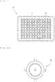
- Fig. 1 is a plan view schematically showing a well plate according to this embodiment.
- Fig. 2A is an explanatory view showing a well formed in the well plate, which is a plan view showing the well when viewed from the upper surface of a plate.
- Fig. 2B is a schematic sectional view of the well formed in the well plate.
- Fig. 3 is a partially enlarged view showing a stepped part formed in the circumferential wall part of the well.
- a well plate 10 is configured so that a plurality of wells 12 are arranged in the upper surface of a plate 11.
- the plate 11 has light transmittance, but there can also be used plates to which light blocking property is imparted, for example, by coloring the plates black, except the bottom surface parts of the wells 12 (the details thereof will be described later).
- the "light transmittance” means transmittance to light within a visible light region (360 nm to 780 nm).
- the entire shape of the plate 11 is rectangular, but may be any other shape in the present disclosure.
- the material constituting the plate 11 is not particularly limited, but, for example, materials which do not affect the observation, detection and measurement of a liquid sample and have excellent surface treatment properties and moldability are preferably used.
- the material include polystyrene-based resins such as polystyrene and acrylonitrile-butadiene-styrene-based resin; polyolefin-based or cyclic polyolefin-based resins such as polypropylene resin, polyethylene resin and ethylene-propylene copolymer; polycarbonate resin; polyethylene terephthalate resin; methacrylic resins such as polymethylmethacrylate resin; vinyl chloride resin; polybutylene terephthalate resin; polyarylate resin; polysulfone resin; polyethersulfone resin; polyetheretherketone resin; polyetherimide resin; fluorine-based resins such as polytetrafluoroethylene; polymethylpentene resin; acrylic resins such as polyacrylonitrile; and cellul
- the dimensions of the plate 11 can vary depending on the intended use.
- the well 12 functions as a containing part for containing and holding the liquid sample as shown in Figs. 2A and 2B .
- the number of the wells preferably ranges from 4 to 1536, more preferably from 96 to 1536.
- the width dimension (aperture dimension) and depth dimension of the respective wells 12 are not particularly limited so long as the wells can be accommodated in the plate 11, and can appropriately be determined depending, for example, on the dimensions of the plate 11.
- the width dimension w can be defined within the range of from 1.
- the depth dimension d can be defined within the range of from 2 mm to 18 mm. It can be said that when the width dimension and depth dimension of the respective wells 12 are increased, the amount of the liquid necessary for the reaction and the like can also be increased, which is preferred in many cases. However, an unnecessary liquid cost would be required when the amounts of the necessary ingredients exceed amounts necessary and sufficient for the reaction and the like.
- the aperture of the well 12 is formed in a circular shape in a plan view.
- the bottom surface part 13 of the well 12 is formed in a flat circular shape.
- the shape of the bottom surface part 13 is also not limited to the case of a circular shape, and can be, for example, a rectangular shape or the like in response to the aperture shape of the well 12.
- the bottom surface part 13 must have transmittance to light within a visible light range.
- the bottom surface part 13 can transmit the irradiated light from the upper side of the well 12, and enables imaging by means of an imaging device which will be described later.
- the circumferential wall part 14 of the well 12 is generally provided so as to rise upward from the circumferential edge of the bottom surface part 13, and is provided with a stepped part 15 in the circumferential direction. More specifically, the part located below the stepped part 15 is a lower circumferential wall part 14b which is provided so as to rise upward from the circumferential edge of the bottom surface part 13. Also, the part located above the stepped part 15 is an upper circumferential wall part 14a which is provided so as to rise upward from the circumferential edge of the stepped part 15.
- the cross sectional area of the upper circumferential wall part 14a is configured to be larger than the cross sectional area of ⁇ the lower circumferential wall part 14b.
- a sufficient size of the cross sectional area of the upper circumferential wall part 14a relative to the cross sectional area of the lower circumferential wall part 14b is such that the circumferential edge part of the liquid level of the liquid sample is blocked at least by the stepped part 15 when the well 12 is observed from the side of the bottom surface part 13.
- the circumferential edge part of the well 12 to be observed can be observed brightly, and the visibility can surely be improved.
- the lower circumferential wall part 14b may rise almost vertically to the bottom surface part 13 or tapered toward the opening direction.
- the upper circumferential wall part 14a may also rise almost vertically to the stepped part 15 or tapered toward the opening direction.
- the taper angle is preferably determined within a range in which the influence on the observation screen due to the meniscus effect of the liquid sample is maximally suppressed.
- the stepped part 15 indicates the lower limit of the liquid level height of a liquid sample contained in the well 12. Therefore, when the well plate 10 of this embodiment is used, the liquid sample must be injected up to a height position such that the liquid level is located above the stepped part 15 and, at least, arrives at the upper circumferential wall part 14a.
- the "liquid level” means the lower surface of the meniscus.
- the height position H of the stepped part 15 in the circumferential wall part 14 is not particularly limited, but is preferably determined so that the volume of the lower circumferential wall part 14b is 1/2 or less relative to the volume of the well 12. Thus, even when the amount of the liquid sample to be injected into the well 12 is minor, the reduction in visibility due to the meniscus effect can be improved. Also, the liquid amount of the liquid sample can appropriately be determined within a range in which the liquid level height is not lower than the height of the stepped part 15.
- the lower limit of the height H of the stepped part 15 is not particularly limited. However, for example, when a culture fluid is used as the liquid sample, the culture fluid is preferably held at a level such that cell culture would not be inhibited in the bottom surface part 13.
- the "height position H of the stepped part 15" means a distance from the bottom surface part 13 to the boundary portion between the bottom surface part 13 and the stepped part 15, in other words, can be said to mean the height of the lower circumferential wall part 14b.
- the inclination angle ⁇ of the stepped part 15 is not particularly limited so long as it falls within the range of 0° or more and less than 90° (see Fig. 3 ).
- the inclination angle ⁇ is preferably within a range such that the cultured cells (spheroidal colonies) do not remain at the stepped part 15, and can be precipitated in the bottom surface part 13 by their own weight.
- the cells can be prevented from remaining and being cultured at the stepped part 15.
- the inclination angle ⁇ of the stepped part 15 is preferably consistent over the whole circumference of the circumferential wall part 14.
- the numerical range for the inclination angle ⁇ is more preferably 30° or more and 75° or less, further preferably 40° or more and 50° or less.
- the "inclination angle ⁇ " means an angle formed between a horizontal surface and an inclined surface of the stepped part 15 when the well plate 10 is placed on the horizontal surface.
- the height h of the stepped part 15 is not particularly limited, and is preferably determined, depending on the values of the cross sectional area of the upper circumferential wall part 14a and inclination angle ⁇ , so that the circumferential edge part of the liquid level of the liquid sample is blocked at least by the stepped part 15.
- the light blocking property can be imparted to the stepped part 15 to block light having a wavelength within a visible light range.
- the circumferential edge in the bottom surface part 13 of the well 12 can be brightened, and the visibility can further be improved.
- Specific examples of the method of imparting the light blocking property include a method of coloring the stepped part 15 black.
- the "light blocking property" means that, when the stepped part 15 is observed from the side of the bottom surface part 13, the average total light transmittance within the wavelength range of visible light (380 to 780 nm) is attenuated to 70% or less, preferably 30% or less, further preferably 10% or less.
- Hydrophilization treatment such as plasma treatment, corona treatment or microwave treatment may be applied to the bottom surface part 13 of the well 12 for promoting physisorption and chemisorption of an analyte ingredient.
- water repellent treatment such as fluorination may be applied in the circumferential wall part 14 in order to prevent the remaining of the cells or the like at the stepped part 15.
- liquid sample examples include reagents and culture fluids for cells.
- culture fluids biological samples such as cells and bacteria cultured under predetermined culturing conditions are used as objects for observation, biochemical analysis and imaging.
- the method of manufacturing the well plate 10 is not particularly limited.
- the well plate 10 when the well plate 10 is made of a resin material, the well plate 10 can easily be prepared, for example, by injection molding, blow molding or injection blow molding or by using a 3D printer.
- the well plate 10 when the well plate 10 is made of glass, the well plate 10 can be prepared by molding through a use of a die or machining.
- FIG. 4 is a schematic view showing a state where the well plate 10 is imaged by an imaging device.
- Fig. 5 is a side view showing a state where a liquid sample has been injected into the well plate 10.
- the XY plane represents a horizontal surface in Fig. 4
- the Z axis represents a vertical axis.
- the imaging device 20 includes, as shown in Fig. 4 , a holder which holds the well plate 10 in an approximately horizontal posture (not shown), an illuminating part 21 arranged above the well plate 10, an imaging part 22 arranged below the well plate 10, and a control part 23 having a CPU which controls the operations of these parts.
- the illuminating part 21 irradiates the well plate 10 held by the holder for vertical illumination with diffused light (ex. white light) from the upper side of the well plate 10.
- the form of the light source of the illuminating part 21 is not particularly limited, and, for example, a point light source, a surface light source and the like can be employed. More specifically, a white LED (Light Emitting Diode) light source and the like can be used.
- the illuminating part 21 may be provided with a diffusion plate for diffusing the irradiated light from the light source to form a surface light source. The irradiation by the illuminating part 21 is carried out while the illuminating part 21 is moved on the XY plane by the control part 23 to be arranged on an arbitrary well 12 as the object for irradiation.
- the imaging part 22 is arranged below the well plate 10, and the imaging part 22 is focused on the bottom surface part 13 of the well 12 in which the biological sample or the like to be imaged is present.
- the focus of the imaging part 22 can be adjusted by the control part 23 vertically moving the imaging part 22 in the Z axis.
- the imaging part 22 can be moved on XY plane together with the illuminating part 21 under the control of the control part 23.
- the center of the well 12 can be positioned on the central axis of the illuminating part 21 and imaging part 22.
- an illumination light path and an imaging light path are made consistent, and the illumination conditions are made constant, whereby the imaging conditions can be maintained well.
- Specific examples of the imaging device 20 include an inverted microscope.
- the liquid sample 16 is injected into the well 12 formed in the well plate 10 in such a manner as shown in Fig. 5 .
- the liquid sample 16 is injected, at least, to a level such that the liquid level 17 of the liquid sample arrives at the upper circumferential wall part 14a.
- the liquid level 17 wets the circumferential wall part due to the interfacial tension of the liquid sample, and thus becomes a concave curved surface to form a meniscus.
- the imaging of the liquid sample 16 is performed by delivering the irradiated light from the upper side of the well 12 by the illuminating part 21 of the imaging device 20 and receiving, in the imaging part 22, the light transmitted through the liquid sample 16 in the well 12 and the bottom surface part 13.
- the irradiated light which has arrived at the circumferential edge near the upper circumferential wall part 14a further travels radially from the center of the well 12 by refraction.
- the circumferential edge of the liquid level 17, when observed from the bottom surface part 13 of the well 12 is blocked by the stepped part 15. Therefore, the imaging part 22 can image the liquid sample in a state where the circumferential edge of the bottom surface part 13 is brightened
- the liquid level of the liquid sample 16 injected into the well 12 is located at a position lower than the height position of the stepped part 15 (indicated as a liquid level 18 in Fig. 5 ), the circumferential edge of the liquid level near the upper circumferential wall part 14a cannot be blocked by the stepped part 15. Therefore, the liquid sample is imaged by the imaging part 22 in a state where the circumferential edge of the bottom surface part 13 is dark.
- a method including arranging the illuminating part 21 below the well plate 10 and arranging the imaging part 22 above the well plate 10 to image the liquid sample 16 is conceivable, but causes the following disadvantage.
- the imaging part 22 images the liquid sample focusing on the bottom surface part 13 of the well 12
- the captured image is sometimes distorted due to the lens effect by the concave meniscus of the liquid level of the liquid sample 16. Therefore, the analysis accuracy is sometime lowered as compared with the case where the liquid sample is imaged from the lower side of the well plate 10.
- the aperture portion of the well 12 is closed by a lid, a plate seal or the like which can be fitted to the well 12 form the viewpoint of preventing the contamination of dust or the like.
- the liquid sample 16 is, for example, a culture fluid for cells and is kept warm at about 36°C, the lid or the like sometimes become cloudy. In that case, the image captured by the imaging part 22 is disadvantageously non-sharp.
- the liquid sample injected into the well 12 is imaged preferably from the lower side through vertical irradiation from the upper side of the well plate 10.
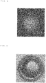
- a well plate made of an acrylic resin and having the following specification was used. It is noted that a well whose upper circumferential wall part and lower circumferential wall part rise respectively almost vertically to the bottom surface part was used.
- a culture fluid DMEM (Dulbecco's Modified Eagle's Medium) (100 ⁇ l) was dropped into the well of the well plate to image the well bottom surface part with an inverted microscope. The result is shown in Fig. 6 .
- a well plate having the following specification was used.
- the well bottom surface part was imaged with an inverted microscope in a similar manner as in Example 1 except the well plate used. The result is shown in Fig. 7 .
- a well plate made of a polystyrene resin including a well having a circumferential wall part in which no stepped part was provided, and having the following specification.
- DMEM 100 ⁇ l was dropped into the well of the well plate to image the well bottom surface part with the inverted microscope. The result is shown in Fig. 8 .
- the amount of DMEM to be dropped was changed to 50 ⁇ l.
- the well bottom surface part was imaged with the inverted microscope in a similar manner as in the Example 1 except the amount. The result is shown in Fig. 9 .
- a well plate including a well having a circumferential wall part in which no stepped part was provided, and having the following specification.
- DMEM 100 ⁇ l was dropped into the well of the well plate to image the bottom surface part of the well with the inverted microscope. The result is shown in Fig. 10 .
Applications Claiming Priority (1)
| Application Number | Priority Date | Filing Date | Title |
|---|---|---|---|
| JP2016130483 | 2016-06-30 |
Publications (2)
| Publication Number | Publication Date |
|---|---|
| EP3263219A1 true EP3263219A1 (fr) | 2018-01-03 |
| EP3263219B1 EP3263219B1 (fr) | 2020-09-09 |
Family
ID=59312953
Family Applications (1)
| Application Number | Title | Priority Date | Filing Date |
|---|---|---|---|
| EP17176789.0A Active EP3263219B1 (fr) | 2016-06-30 | 2017-06-20 | Plaque à puits et methode pour sa utilisation |
Country Status (6)
| Country | Link |
|---|---|
| US (1) | US20180001318A1 (fr) |
| EP (1) | EP3263219B1 (fr) |
| JP (1) | JP2018009968A (fr) |
| KR (1) | KR20180003449A (fr) |
| CN (1) | CN107561014A (fr) |
| TW (1) | TWI631326B (fr) |
Families Citing this family (2)
| Publication number | Priority date | Publication date | Assignee | Title |
|---|---|---|---|---|
| US20210301237A1 (en) * | 2018-05-30 | 2021-09-30 | Sun Bioscience Sa | Well for cultivating biological material |
| CN108707551B (zh) * | 2018-06-27 | 2022-12-20 | 深圳市深研生物科技有限公司 | 一种细胞观察方法 |
Citations (8)
| Publication number | Priority date | Publication date | Assignee | Title |
|---|---|---|---|---|
| JPH05181068A (ja) | 1991-08-20 | 1993-07-23 | Hoya Corp | メニスカス制御用平板 |
| US6051191A (en) * | 1996-11-25 | 2000-04-18 | Porvair Plc | Microplates |
| WO2003036265A2 (fr) * | 2001-10-26 | 2003-05-01 | Virtual Arrays, Inc. | Systemes de dosage a communication de fluides reglable |
| JP2004340759A (ja) * | 2003-05-15 | 2004-12-02 | Tdk Corp | 分析試料容器、分析装置および分析方法 |
| US20080020455A1 (en) * | 2006-07-20 | 2008-01-24 | Ibidi Gmbh | Specimen Carrier for the Study of Cell Growth |
| JP2012127964A (ja) * | 2010-12-15 | 2012-07-05 | F Hoffmann-La Roche Ag | 容量の小さい液体の光度測定のためのキュベット |
| JP2012147739A (ja) | 2011-01-20 | 2012-08-09 | Nikon Corp | 観察装置 |
| US9360433B1 (en) * | 2013-05-21 | 2016-06-07 | Indevr, Inc. | Detection of agglutination by optical density measurement |
Family Cites Families (12)
| Publication number | Priority date | Publication date | Assignee | Title |
|---|---|---|---|---|
| KR100236506B1 (ko) * | 1990-11-29 | 2000-01-15 | 퍼킨-엘머시터스인스트루먼츠 | 폴리머라제 연쇄 반응 수행 장치 |
| US20020057995A1 (en) * | 2000-09-15 | 2002-05-16 | Guido Desie | Microtiter plate |
| WO2003022421A2 (fr) * | 2001-09-07 | 2003-03-20 | Corning Incorporated | Ensemble de micro-colonnes sur plate-forme pour analyses a fort debit |
| JP2004245727A (ja) * | 2003-02-14 | 2004-09-02 | Olympus Corp | マイクロプレート |
| US7858044B2 (en) * | 2003-04-30 | 2010-12-28 | Nexus Biosystems, Inc. | Multi-well plate providing a high-density storage and assay platform |
| EP1905513A1 (fr) * | 2006-09-13 | 2008-04-02 | Institut Curie | Procédés et dispositifs de prélèvement des fluides |
| JP5872895B2 (ja) * | 2008-05-05 | 2016-03-01 | スリーエム イノベイティブ プロパティズ カンパニー | 音響複合体 |
| CA2724106C (fr) * | 2009-12-10 | 2018-04-17 | F. Hoffmann-La Roche Ag | Plaque et couvercle multipuits |
| RU2548619C1 (ru) * | 2011-03-08 | 2015-04-20 | Японское Агентство По Науке И Технике | Способ герметизации гранул, способ обнаружения молекулы-мишени, матрица, набор и устройство для обнаружения молекулы-мишени |
| US8968684B2 (en) * | 2011-04-28 | 2015-03-03 | Bin Lian | Microplates, reaction modules and detection systems |
| CN105073587B (zh) * | 2013-01-10 | 2018-01-09 | 干细胞技术公司 | 弯月面降低构件 |
| EP2948251A1 (fr) * | 2013-01-24 | 2015-12-02 | SABIC Global Technologies B.V. | Plaque de micro-puits fabriquée à partir d'un polyester-polycarbonate |
-
2017
- 2017-05-01 JP JP2017091048A patent/JP2018009968A/ja active Pending
- 2017-05-04 TW TW106114748A patent/TWI631326B/zh not_active IP Right Cessation
- 2017-06-20 EP EP17176789.0A patent/EP3263219B1/fr active Active
- 2017-06-26 CN CN201710493248.XA patent/CN107561014A/zh active Pending
- 2017-06-27 KR KR1020170081250A patent/KR20180003449A/ko not_active Application Discontinuation
- 2017-06-29 US US15/638,219 patent/US20180001318A1/en not_active Abandoned
Patent Citations (8)
| Publication number | Priority date | Publication date | Assignee | Title |
|---|---|---|---|---|
| JPH05181068A (ja) | 1991-08-20 | 1993-07-23 | Hoya Corp | メニスカス制御用平板 |
| US6051191A (en) * | 1996-11-25 | 2000-04-18 | Porvair Plc | Microplates |
| WO2003036265A2 (fr) * | 2001-10-26 | 2003-05-01 | Virtual Arrays, Inc. | Systemes de dosage a communication de fluides reglable |
| JP2004340759A (ja) * | 2003-05-15 | 2004-12-02 | Tdk Corp | 分析試料容器、分析装置および分析方法 |
| US20080020455A1 (en) * | 2006-07-20 | 2008-01-24 | Ibidi Gmbh | Specimen Carrier for the Study of Cell Growth |
| JP2012127964A (ja) * | 2010-12-15 | 2012-07-05 | F Hoffmann-La Roche Ag | 容量の小さい液体の光度測定のためのキュベット |
| JP2012147739A (ja) | 2011-01-20 | 2012-08-09 | Nikon Corp | 観察装置 |
| US9360433B1 (en) * | 2013-05-21 | 2016-06-07 | Indevr, Inc. | Detection of agglutination by optical density measurement |
Also Published As
| Publication number | Publication date |
|---|---|
| TW201802450A (zh) | 2018-01-16 |
| KR20180003449A (ko) | 2018-01-09 |
| CN107561014A (zh) | 2018-01-09 |
| US20180001318A1 (en) | 2018-01-04 |
| JP2018009968A (ja) | 2018-01-18 |
| TWI631326B (zh) | 2018-08-01 |
| EP3263219B1 (fr) | 2020-09-09 |
Similar Documents
| Publication | Publication Date | Title |
|---|---|---|
| US20160170195A1 (en) | Arrangement for Light Sheet Microscopy | |
| EP3004838B1 (fr) | Cytomètre de formation d'image | |
| WO2016052078A1 (fr) | Récipient en plastique | |
| US20080063251A1 (en) | Method and Device for Identifying an Image of a Well in an Image of a Well-Bearing | |
| EP1859866A1 (fr) | Plaque à puits | |
| JP2021503078A (ja) | 光学測定用試料収容器 | |
| EP1886177B1 (fr) | Chambre de comptage, d'evaluation de viabilite, d'analyse et de manipulation | |
| EP3263219B1 (fr) | Plaque à puits et methode pour sa utilisation | |
| JP6851582B2 (ja) | 細胞培養用顕微鏡スライドの改良およびそれに関連する改良 | |
| AU2016232975C1 (en) | Method and apparatus for microscopy | |
| US11841491B2 (en) | Observation vessel, sample preparation method, and observation method | |
| JP4679847B2 (ja) | 細胞の解析方法 | |
| US10606058B2 (en) | Microscope slide for liquid cultures | |
| US7915033B2 (en) | Incubation container system | |
| US8961907B2 (en) | Apparatus for the detection and analysis of particles in fluids | |
| US20230173519A1 (en) | Imaging apparatus for imaging a nozzle section of a droplet dispenser device, dispenser apparatus including the imaging apparatus, and applications thereof | |
| WO2024085230A1 (fr) | Élément de canal et dispositif de manipulation d'objet fin | |
| US20210162401A1 (en) | Method and apparatus for providing an isolated single cell | |
| Zhang et al. | Tracking of Lineage Mass via Quantitative Phase Imaging and Confinement in Low Refractive Index Microwells | |
| JP2017176073A (ja) | 細胞培養用ウェルプレート及び当該細胞培養用ウェルプレートにおけるウェル内部の培養液中の細胞を観測する方法 | |
| NZ578644A (en) | Analysis of particles | |
| JP2012215610A (ja) | ウェルプレート、およびウェルプレートを用いた観察方法 |
Legal Events
| Date | Code | Title | Description |
|---|---|---|---|
| PUAI | Public reference made under article 153(3) epc to a published international application that has entered the european phase |
Free format text: ORIGINAL CODE: 0009012 |
|
| STAA | Information on the status of an ep patent application or granted ep patent |
Free format text: STATUS: THE APPLICATION HAS BEEN PUBLISHED |
|
| AK | Designated contracting states |
Kind code of ref document: A1 Designated state(s): AL AT BE BG CH CY CZ DE DK EE ES FI FR GB GR HR HU IE IS IT LI LT LU LV MC MK MT NL NO PL PT RO RS SE SI SK SM TR |
|
| AX | Request for extension of the european patent |
Extension state: BA ME |
|
| STAA | Information on the status of an ep patent application or granted ep patent |
Free format text: STATUS: REQUEST FOR EXAMINATION WAS MADE |
|
| 17P | Request for examination filed |
Effective date: 20180703 |
|
| RBV | Designated contracting states (corrected) |
Designated state(s): AL AT BE BG CH CY CZ DE DK EE ES FI FR GB GR HR HU IE IS IT LI LT LU LV MC MK MT NL NO PL PT RO RS SE SI SK SM TR |
|
| STAA | Information on the status of an ep patent application or granted ep patent |
Free format text: STATUS: EXAMINATION IS IN PROGRESS |
|
| 17Q | First examination report despatched |
Effective date: 20180817 |
|
| GRAP | Despatch of communication of intention to grant a patent |
Free format text: ORIGINAL CODE: EPIDOSNIGR1 |
|
| STAA | Information on the status of an ep patent application or granted ep patent |
Free format text: STATUS: GRANT OF PATENT IS INTENDED |
|
| GRAS | Grant fee paid |
Free format text: ORIGINAL CODE: EPIDOSNIGR3 |
|
| INTG | Intention to grant announced |
Effective date: 20200324 |
|
| GRAA | (expected) grant |
Free format text: ORIGINAL CODE: 0009210 |
|
| STAA | Information on the status of an ep patent application or granted ep patent |
Free format text: STATUS: THE PATENT HAS BEEN GRANTED |
|
| AK | Designated contracting states |
Kind code of ref document: B1 Designated state(s): AL AT BE BG CH CY CZ DE DK EE ES FI FR GB GR HR HU IE IS IT LI LT LU LV MC MK MT NL NO PL PT RO RS SE SI SK SM TR |
|
| REG | Reference to a national code |
Ref country code: GB Ref legal event code: FG4D |
|
| REG | Reference to a national code |
Ref country code: AT Ref legal event code: REF Ref document number: 1310884 Country of ref document: AT Kind code of ref document: T Effective date: 20200915 Ref country code: CH Ref legal event code: EP |
|
| REG | Reference to a national code |
Ref country code: IE Ref legal event code: FG4D |
|
| REG | Reference to a national code |
Ref country code: DE Ref legal event code: R096 Ref document number: 602017023131 Country of ref document: DE |
|
| REG | Reference to a national code |
Ref country code: LT Ref legal event code: MG4D |
|
| PG25 | Lapsed in a contracting state [announced via postgrant information from national office to epo] |
Ref country code: SE Free format text: LAPSE BECAUSE OF FAILURE TO SUBMIT A TRANSLATION OF THE DESCRIPTION OR TO PAY THE FEE WITHIN THE PRESCRIBED TIME-LIMIT Effective date: 20200909 Ref country code: BG Free format text: LAPSE BECAUSE OF FAILURE TO SUBMIT A TRANSLATION OF THE DESCRIPTION OR TO PAY THE FEE WITHIN THE PRESCRIBED TIME-LIMIT Effective date: 20201209 Ref country code: NO Free format text: LAPSE BECAUSE OF FAILURE TO SUBMIT A TRANSLATION OF THE DESCRIPTION OR TO PAY THE FEE WITHIN THE PRESCRIBED TIME-LIMIT Effective date: 20201209 Ref country code: HR Free format text: LAPSE BECAUSE OF FAILURE TO SUBMIT A TRANSLATION OF THE DESCRIPTION OR TO PAY THE FEE WITHIN THE PRESCRIBED TIME-LIMIT Effective date: 20200909 Ref country code: FI Free format text: LAPSE BECAUSE OF FAILURE TO SUBMIT A TRANSLATION OF THE DESCRIPTION OR TO PAY THE FEE WITHIN THE PRESCRIBED TIME-LIMIT Effective date: 20200909 Ref country code: LT Free format text: LAPSE BECAUSE OF FAILURE TO SUBMIT A TRANSLATION OF THE DESCRIPTION OR TO PAY THE FEE WITHIN THE PRESCRIBED TIME-LIMIT Effective date: 20200909 Ref country code: GR Free format text: LAPSE BECAUSE OF FAILURE TO SUBMIT A TRANSLATION OF THE DESCRIPTION OR TO PAY THE FEE WITHIN THE PRESCRIBED TIME-LIMIT Effective date: 20201210 |
|
| REG | Reference to a national code |
Ref country code: AT Ref legal event code: MK05 Ref document number: 1310884 Country of ref document: AT Kind code of ref document: T Effective date: 20200909 |
|
| REG | Reference to a national code |
Ref country code: NL Ref legal event code: MP Effective date: 20200909 |
|
| PG25 | Lapsed in a contracting state [announced via postgrant information from national office to epo] |
Ref country code: LV Free format text: LAPSE BECAUSE OF FAILURE TO SUBMIT A TRANSLATION OF THE DESCRIPTION OR TO PAY THE FEE WITHIN THE PRESCRIBED TIME-LIMIT Effective date: 20200909 Ref country code: PL Free format text: LAPSE BECAUSE OF FAILURE TO SUBMIT A TRANSLATION OF THE DESCRIPTION OR TO PAY THE FEE WITHIN THE PRESCRIBED TIME-LIMIT Effective date: 20200909 Ref country code: RS Free format text: LAPSE BECAUSE OF FAILURE TO SUBMIT A TRANSLATION OF THE DESCRIPTION OR TO PAY THE FEE WITHIN THE PRESCRIBED TIME-LIMIT Effective date: 20200909 |
|
| PG25 | Lapsed in a contracting state [announced via postgrant information from national office to epo] |
Ref country code: CZ Free format text: LAPSE BECAUSE OF FAILURE TO SUBMIT A TRANSLATION OF THE DESCRIPTION OR TO PAY THE FEE WITHIN THE PRESCRIBED TIME-LIMIT Effective date: 20200909 Ref country code: RO Free format text: LAPSE BECAUSE OF FAILURE TO SUBMIT A TRANSLATION OF THE DESCRIPTION OR TO PAY THE FEE WITHIN THE PRESCRIBED TIME-LIMIT Effective date: 20200909 Ref country code: PT Free format text: LAPSE BECAUSE OF FAILURE TO SUBMIT A TRANSLATION OF THE DESCRIPTION OR TO PAY THE FEE WITHIN THE PRESCRIBED TIME-LIMIT Effective date: 20210111 Ref country code: EE Free format text: LAPSE BECAUSE OF FAILURE TO SUBMIT A TRANSLATION OF THE DESCRIPTION OR TO PAY THE FEE WITHIN THE PRESCRIBED TIME-LIMIT Effective date: 20200909 Ref country code: SM Free format text: LAPSE BECAUSE OF FAILURE TO SUBMIT A TRANSLATION OF THE DESCRIPTION OR TO PAY THE FEE WITHIN THE PRESCRIBED TIME-LIMIT Effective date: 20200909 |
|
| PG25 | Lapsed in a contracting state [announced via postgrant information from national office to epo] |
Ref country code: ES Free format text: LAPSE BECAUSE OF FAILURE TO SUBMIT A TRANSLATION OF THE DESCRIPTION OR TO PAY THE FEE WITHIN THE PRESCRIBED TIME-LIMIT Effective date: 20200909 Ref country code: AL Free format text: LAPSE BECAUSE OF FAILURE TO SUBMIT A TRANSLATION OF THE DESCRIPTION OR TO PAY THE FEE WITHIN THE PRESCRIBED TIME-LIMIT Effective date: 20200909 Ref country code: AT Free format text: LAPSE BECAUSE OF FAILURE TO SUBMIT A TRANSLATION OF THE DESCRIPTION OR TO PAY THE FEE WITHIN THE PRESCRIBED TIME-LIMIT Effective date: 20200909 Ref country code: IS Free format text: LAPSE BECAUSE OF FAILURE TO SUBMIT A TRANSLATION OF THE DESCRIPTION OR TO PAY THE FEE WITHIN THE PRESCRIBED TIME-LIMIT Effective date: 20210109 |
|
| REG | Reference to a national code |
Ref country code: DE Ref legal event code: R097 Ref document number: 602017023131 Country of ref document: DE |
|
| PG25 | Lapsed in a contracting state [announced via postgrant information from national office to epo] |
Ref country code: SK Free format text: LAPSE BECAUSE OF FAILURE TO SUBMIT A TRANSLATION OF THE DESCRIPTION OR TO PAY THE FEE WITHIN THE PRESCRIBED TIME-LIMIT Effective date: 20200909 |
|
| PLBE | No opposition filed within time limit |
Free format text: ORIGINAL CODE: 0009261 |
|
| STAA | Information on the status of an ep patent application or granted ep patent |
Free format text: STATUS: NO OPPOSITION FILED WITHIN TIME LIMIT |
|
| PGFP | Annual fee paid to national office [announced via postgrant information from national office to epo] |
Ref country code: FR Payment date: 20210625 Year of fee payment: 5 Ref country code: DE Payment date: 20210630 Year of fee payment: 5 |
|
| 26N | No opposition filed |
Effective date: 20210610 |
|
| PG25 | Lapsed in a contracting state [announced via postgrant information from national office to epo] |
Ref country code: DK Free format text: LAPSE BECAUSE OF FAILURE TO SUBMIT A TRANSLATION OF THE DESCRIPTION OR TO PAY THE FEE WITHIN THE PRESCRIBED TIME-LIMIT Effective date: 20200909 Ref country code: SI Free format text: LAPSE BECAUSE OF FAILURE TO SUBMIT A TRANSLATION OF THE DESCRIPTION OR TO PAY THE FEE WITHIN THE PRESCRIBED TIME-LIMIT Effective date: 20200909 |
|
| PGFP | Annual fee paid to national office [announced via postgrant information from national office to epo] |
Ref country code: GB Payment date: 20210630 Year of fee payment: 5 |
|
| PG25 | Lapsed in a contracting state [announced via postgrant information from national office to epo] |
Ref country code: IT Free format text: LAPSE BECAUSE OF FAILURE TO SUBMIT A TRANSLATION OF THE DESCRIPTION OR TO PAY THE FEE WITHIN THE PRESCRIBED TIME-LIMIT Effective date: 20200909 |
|
| PG25 | Lapsed in a contracting state [announced via postgrant information from national office to epo] |
Ref country code: MC Free format text: LAPSE BECAUSE OF FAILURE TO SUBMIT A TRANSLATION OF THE DESCRIPTION OR TO PAY THE FEE WITHIN THE PRESCRIBED TIME-LIMIT Effective date: 20200909 |
|
| REG | Reference to a national code |
Ref country code: CH Ref legal event code: PL |
|
| REG | Reference to a national code |
Ref country code: BE Ref legal event code: MM Effective date: 20210630 |
|
| PG25 | Lapsed in a contracting state [announced via postgrant information from national office to epo] |
Ref country code: LU Free format text: LAPSE BECAUSE OF NON-PAYMENT OF DUE FEES Effective date: 20210620 |
|
| PG25 | Lapsed in a contracting state [announced via postgrant information from national office to epo] |
Ref country code: LI Free format text: LAPSE BECAUSE OF NON-PAYMENT OF DUE FEES Effective date: 20210630 Ref country code: IE Free format text: LAPSE BECAUSE OF NON-PAYMENT OF DUE FEES Effective date: 20210620 Ref country code: CH Free format text: LAPSE BECAUSE OF NON-PAYMENT OF DUE FEES Effective date: 20210630 |
|
| PG25 | Lapsed in a contracting state [announced via postgrant information from national office to epo] |
Ref country code: BE Free format text: LAPSE BECAUSE OF NON-PAYMENT OF DUE FEES Effective date: 20210630 |
|
| REG | Reference to a national code |
Ref country code: DE Ref legal event code: R119 Ref document number: 602017023131 Country of ref document: DE |
|
| GBPC | Gb: european patent ceased through non-payment of renewal fee |
Effective date: 20220620 |
|
| PG25 | Lapsed in a contracting state [announced via postgrant information from national office to epo] |
Ref country code: FR Free format text: LAPSE BECAUSE OF NON-PAYMENT OF DUE FEES Effective date: 20220630 |
|
| PG25 | Lapsed in a contracting state [announced via postgrant information from national office to epo] |
Ref country code: HU Free format text: LAPSE BECAUSE OF FAILURE TO SUBMIT A TRANSLATION OF THE DESCRIPTION OR TO PAY THE FEE WITHIN THE PRESCRIBED TIME-LIMIT; INVALID AB INITIO Effective date: 20170620 Ref country code: GB Free format text: LAPSE BECAUSE OF NON-PAYMENT OF DUE FEES Effective date: 20220620 Ref country code: DE Free format text: LAPSE BECAUSE OF NON-PAYMENT OF DUE FEES Effective date: 20230103 |
|
| PG25 | Lapsed in a contracting state [announced via postgrant information from national office to epo] |
Ref country code: NL Free format text: LAPSE BECAUSE OF NON-PAYMENT OF DUE FEES Effective date: 20200923 Ref country code: CY Free format text: LAPSE BECAUSE OF FAILURE TO SUBMIT A TRANSLATION OF THE DESCRIPTION OR TO PAY THE FEE WITHIN THE PRESCRIBED TIME-LIMIT Effective date: 20200909 |
|
| PG25 | Lapsed in a contracting state [announced via postgrant information from national office to epo] |
Ref country code: MK Free format text: LAPSE BECAUSE OF FAILURE TO SUBMIT A TRANSLATION OF THE DESCRIPTION OR TO PAY THE FEE WITHIN THE PRESCRIBED TIME-LIMIT Effective date: 20200909 |