EP3263166B1 - Gasgenerator - Google Patents
Gasgenerator Download PDFInfo
- Publication number
- EP3263166B1 EP3263166B1 EP17178960.5A EP17178960A EP3263166B1 EP 3263166 B1 EP3263166 B1 EP 3263166B1 EP 17178960 A EP17178960 A EP 17178960A EP 3263166 B1 EP3263166 B1 EP 3263166B1
- Authority
- EP
- European Patent Office
- Prior art keywords
- gas
- pathway
- hydrogen
- filter
- generator
- Prior art date
- Legal status (The legal status is an assumption and is not a legal conclusion. Google has not performed a legal analysis and makes no representation as to the accuracy of the status listed.)
- Active
Links
Images


Classifications
-
- A—HUMAN NECESSITIES
- A61—MEDICAL OR VETERINARY SCIENCE; HYGIENE
- A61M—DEVICES FOR INTRODUCING MEDIA INTO, OR ONTO, THE BODY; DEVICES FOR TRANSDUCING BODY MEDIA OR FOR TAKING MEDIA FROM THE BODY; DEVICES FOR PRODUCING OR ENDING SLEEP OR STUPOR
- A61M16/00—Devices for influencing the respiratory system of patients by gas treatment, e.g. ventilators; Tracheal tubes
- A61M16/10—Preparation of respiratory gases or vapours
- A61M16/105—Filters
- A61M16/106—Filters in a path
- A61M16/107—Filters in a path in the inspiratory path
-
- B—PERFORMING OPERATIONS; TRANSPORTING
- B01—PHYSICAL OR CHEMICAL PROCESSES OR APPARATUS IN GENERAL
- B01D—SEPARATION
- B01D46/00—Filters or filtering processes specially modified for separating dispersed particles from gases or vapours
- B01D46/10—Particle separators, e.g. dust precipitators, using filter plates, sheets or pads having plane surfaces
-
- B—PERFORMING OPERATIONS; TRANSPORTING
- B01—PHYSICAL OR CHEMICAL PROCESSES OR APPARATUS IN GENERAL
- B01D—SEPARATION
- B01D46/00—Filters or filtering processes specially modified for separating dispersed particles from gases or vapours
- B01D46/56—Filters or filtering processes specially modified for separating dispersed particles from gases or vapours with multiple filtering elements, characterised by their mutual disposition
-
- B—PERFORMING OPERATIONS; TRANSPORTING
- B01—PHYSICAL OR CHEMICAL PROCESSES OR APPARATUS IN GENERAL
- B01F—MIXING, e.g. DISSOLVING, EMULSIFYING OR DISPERSING
- B01F23/00—Mixing according to the phases to be mixed, e.g. dispersing or emulsifying
- B01F23/20—Mixing gases with liquids
- B01F23/21—Mixing gases with liquids by introducing liquids into gaseous media
- B01F23/213—Mixing gases with liquids by introducing liquids into gaseous media by spraying or atomising of the liquids
-
- C—CHEMISTRY; METALLURGY
- C25—ELECTROLYTIC OR ELECTROPHORETIC PROCESSES; APPARATUS THEREFOR
- C25B—ELECTROLYTIC OR ELECTROPHORETIC PROCESSES FOR THE PRODUCTION OF COMPOUNDS OR NON-METALS; APPARATUS THEREFOR
- C25B1/00—Electrolytic production of inorganic compounds or non-metals
- C25B1/01—Products
- C25B1/02—Hydrogen or oxygen
- C25B1/04—Hydrogen or oxygen by electrolysis of water
-
- C—CHEMISTRY; METALLURGY
- C25—ELECTROLYTIC OR ELECTROPHORETIC PROCESSES; APPARATUS THEREFOR
- C25B—ELECTROLYTIC OR ELECTROPHORETIC PROCESSES FOR THE PRODUCTION OF COMPOUNDS OR NON-METALS; APPARATUS THEREFOR
- C25B15/00—Operating or servicing cells
- C25B15/02—Process control or regulation
-
- C—CHEMISTRY; METALLURGY
- C25—ELECTROLYTIC OR ELECTROPHORETIC PROCESSES; APPARATUS THEREFOR
- C25B—ELECTROLYTIC OR ELECTROPHORETIC PROCESSES FOR THE PRODUCTION OF COMPOUNDS OR NON-METALS; APPARATUS THEREFOR
- C25B15/00—Operating or servicing cells
- C25B15/02—Process control or regulation
- C25B15/023—Measuring, analysing or testing during electrolytic production
- C25B15/025—Measuring, analysing or testing during electrolytic production of electrolyte parameters
-
- C—CHEMISTRY; METALLURGY
- C25—ELECTROLYTIC OR ELECTROPHORETIC PROCESSES; APPARATUS THEREFOR
- C25B—ELECTROLYTIC OR ELECTROPHORETIC PROCESSES FOR THE PRODUCTION OF COMPOUNDS OR NON-METALS; APPARATUS THEREFOR
- C25B9/00—Cells or assemblies of cells; Constructional parts of cells; Assemblies of constructional parts, e.g. electrode-diaphragm assemblies; Process-related cell features
- C25B9/17—Cells comprising dimensionally-stable non-movable electrodes; Assemblies of constructional parts thereof
-
- C—CHEMISTRY; METALLURGY
- C02—TREATMENT OF WATER, WASTE WATER, SEWAGE, OR SLUDGE
- C02F—TREATMENT OF WATER, WASTE WATER, SEWAGE, OR SLUDGE
- C02F1/00—Treatment of water, waste water, or sewage
- C02F1/46—Treatment of water, waste water, or sewage by electrochemical methods
- C02F1/461—Treatment of water, waste water, or sewage by electrochemical methods by electrolysis
- C02F1/46104—Devices therefor; Their operating or servicing
- C02F1/4618—Devices therefor; Their operating or servicing for producing "ionised" acidic or basic water
-
- Y—GENERAL TAGGING OF NEW TECHNOLOGICAL DEVELOPMENTS; GENERAL TAGGING OF CROSS-SECTIONAL TECHNOLOGIES SPANNING OVER SEVERAL SECTIONS OF THE IPC; TECHNICAL SUBJECTS COVERED BY FORMER USPC CROSS-REFERENCE ART COLLECTIONS [XRACs] AND DIGESTS
- Y02—TECHNOLOGIES OR APPLICATIONS FOR MITIGATION OR ADAPTATION AGAINST CLIMATE CHANGE
- Y02E—REDUCTION OF GREENHOUSE GAS [GHG] EMISSIONS, RELATED TO ENERGY GENERATION, TRANSMISSION OR DISTRIBUTION
- Y02E60/00—Enabling technologies; Technologies with a potential or indirect contribution to GHG emissions mitigation
- Y02E60/30—Hydrogen technology
- Y02E60/36—Hydrogen production from non-carbon containing sources, e.g. by water electrolysis
Definitions
- the present invention relates to a gas generator, and more particularly, the present invention relates to a gas generator with a function of filtering out an electrolyte in a gas generated from the gas generator.
- O+ instable oxygen species
- the free radicals are usually generated due to diseases, diet, environment and one's lifestyle, but they can be excreted in the form of water by reacting with the inhaled hydrogen.
- the amount of free radicals in the human body can be reduced, thereby restoring the body condition from an acidic state to an alkaline state, achieving an anti-oxidation, anti-aging and beauty health effect, and even eliminating chronic diseases.
- there are clinical experiments showing that patients who need to inhale a high concentration of oxygen for an extended period of time would experience lung damage and the lung damage, and they could be ameliorated by inhaling hydrogen.
- the gas with hydrogen is generated by electrolyzing electrolyzed water usually with high temperature and electrolyte. It is unsuitable for person to breathe directly. Additionally, if a user wants to breathe a healthy gas, the gas with hydrogen will need to be mixed with an atomizing gas or a volatile essential by another device for formed the healthy gas, thereby causing inconvenience in the use of the conventional electrolytic apparatus.
- EP 3 018 103 A2 discloses a gas generator which can prevent explosions and has function of controlling the temperature of the electrolyzed water and cooling down the electrolyzed water after generated hydrogen-oxygen mixed gas.
- US 20150190604 A1 discloses a gas generating system for health use that generates a gas mixture of hydrogen and oxygen comprising a hydrogen-oxygen gas generator and an atomized gas generator.
- the present invention is to provide a gas generator. Firstly, the gas generator electrolyzes liquid water to generate a gas with hydrogen. Then the gas generator condenses the gas with hydrogen and filters out electrolyte in the gas with hydrogen. After that, the gas generator mixes the gas with hydrogen with an atomizing gas to generate a healthy gas for a person to breathe suitably.
- the present invention provides a gas generator comprising an electrolytic cell, a condensate filter device, and an atomizing device.
- the electrolytic cell contains electrolyzed water, wherein the electrolyzed water comprises an electrolyte.
- the electrolytic cell is used for electrolyzing the electrolyzed water to generate a gas with hydrogen.
- the condensate filter device comprises a gas pathway, a filter, and an isolated component.
- the gas pathway is used for receiving the gas with hydrogen.
- the filter is configured in the gas pathway for filtering the gas with hydrogen to generate a filtered gas with hydrogen.
- the isolated component is configured in the condensate filter device for limiting the movement of the filter in the gas pathway.
- the condensate filter device has an inlet and a vent.
- the inlet is configured to receive the gas with hydrogen.
- the vent is configured to output the filtered gas with hydrogen.
- the condensate filter device has a bottom cover of the gas pathway on which the isolated component is positioned.
- the filter comprises a plurality of filter films separated by the isolated component and distributed on the same plane of the bottom cover of the gas pathway.
- the atomizing device is used for receiving the filtered gas with hydrogen, wherein the atomizing device further generates an atomizing gas to be mixed with the filtered gas with hydrogen to generate a healthy gas.
- the isolated component can be an isolated cube or a pathway barrier sheet.
- the condensate filter device has the inlet and the vent, and the inlet and the vent are connected to the gas pathway respectively.
- the gas with hydrogen enters the gas pathway through the inlet.
- the vent is used for outputting the filtered gas with hydrogen.
- the isolated component is used for preventing the filter from flowing into the inlet or the vent by limiting the movement of the filter in the gas pathway. It should be understood that the word "limiting" of the present invention is not equal to "fixing", but reducing the degree of the filter movement.
- the condensate filter device comprises a top cover of the gas pathway and the bottom cover of the gas pathway.
- the top cover of the gas pathway is configured on the bottom cover of the gas pathway, and the gas pathway is formed when the top cover of the gas pathway is combined with the bottom cover of the gas pathway.
- the bottom cover of the gas pathway comprises a pathway substrate, and the pathway barrier sheet is configured on the pathway substrate.
- the gas pathway meanderingly distributed over the condensate filter device is formed when the top cover of the gas pathway is combined with the bottom cover of the gas pathway.
- the pathway substrate and the isolated component are formed integrally by one process.
- the filter comprises a plurality of filter films, and each filter film is limited by the isolated component.
- the gas generator of the present invention further comprises a humidification device connected between the condensate filter device and the atomizing device.
- the humidification device is used for further moisturizing and filtering the filtered gas with hydrogen received from the vent and outputting the filtered gas with hydrogen to the atomizing device.
- the priority of the present invention is to provide a gas generator.
- a gas with hydrogen generated by an electrolytic cell is condensed and filtered out electrolytes with a condensate filter device, and then the gas with hydrogen is mixed with an atomizing gas generated by an atomizing device to generate a healthy gas for humans to breathe suitably.
- the gas generator of the present invention comprises a humidification device connected between the condensate filter device and the atomizing device, wherein the humidification device is used for further filtering out impurities in the gas with hydrogen to provide a more suitable healthy gas for humans to breathe.
- FIG. 1 shows a schematic diagram of the gas generator 1 in one embodiment of the present invention
- FIG. 2 shows a schematic diagram of the condensate filter device 14 and the electrolytic cell 12 of the gas generator 1 in one embodiment of the present invention
- FIG. 3 shows an explosion diagram of the condensate filter device 14 of the gas generator 1 in one embodiment of the present invention
- the gas generator 1 of the present invention comprises an electrolytic cell 12, a condensate filter device 14, and an atomizing device 16.
- the electrolytic cell 12 contains electrolyzed water, wherein the electrolyzed water comprises an electrolyte, and the electrolytic cell 12 is used for electrolyzing the electrolyzed water to generate a gas with hydrogen.
- the condensate filter device 14 comprises a gas pathway 141, a filter 142, and an isolated component 143.
- the gas pathway 141 is used for receiving the gas with hydrogen.
- the filter 142 is configured in the gas pathway 141 for filtering the gas with hydrogen to generate a filtered gas with hydrogen.
- the isolated component 143 is configured in the condensate filter device 14 for limiting the movement of the filter in the gas pathway.
- the atomizing device 16 is used for receiving the filtered gas with hydrogen, wherein the atomizing device 16 further generates an atomizing gas to be mixed with the filtered gas with hydrogen to generate a healthy gas.
- the isolated component 143 can be an isolated cube 1431 or a pathway barrier sheet 1432.
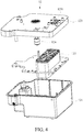
- FIG. 4 shows an explosion diagram of the electrolytic cell 12 of the gas generator 1 in one embodiment of the present invention.
- the electrolytic cell 12 comprises a tank 121, an electrolysis device 122, and an upper cover of the electrolytic cell 123.
- the tank 121 contains electrolyzed water including an electrolyte, wherein the electrolyte can be, but not limited to, sodium hydroxide. In practical application, the electrolyte can be calcium carbonate or sodium chloride. Furthermore, the electrolyte can be a food grade of sodium hydroxide.
- the electrolysis device 122 is configured in the tank 121 for electrolyzing the electrolyzed water in the tank 121. Wherein, the electrolysis device 122 can be configured in the tank 121 by a fixed plate.
- the electrolysis device 122 can be assembled by a plurality of electrodes, and the plurality of electrodes are respectively disposed within the electrolysis device 122 at intervals to form a plurality of electrode channels for speeding up the generation of the gas with hydrogen by electrolyzing the electrolyzed water.
- the upper cover of the electrolytic cell 123 is configured on the tank 121 for separating the electrolyzed water from others. Wherein, the upper cover of the electrolytic cell 123 has an outlet of the electrolytic cell 1231 for outputting the gas with hydrogen generated by electrolyzing the electrolyzed water from the electrolytic cell 12.
- the electrolytic cell 12 can further comprises a water level meter 124 for detecting and alarming the remaining water level of the electrolyzed water in the tank 12 to avoid the danger of empty burning in the electrolytic cell 12.
- FIG. 5 shows an explosion diagram of devices above the electrolytic cell 12 of the gas generator 1 in one embodiment of the present invention.
- the outlet of the electrolytic cell 1231 is connectted to an electrolytic gas connecting channel 1831 above the outlet of the electrolytic cell 1231, wherein the electrolytic gas connecting channel 1831 is used for outputting the gas with hydrogen to the condensate filter device 14.
- the condensate filter device 14 comprises a top cover of the gas pathway 1411 and a bottom cover of the gas pathway 1412.
- the top cover of the gas pathway 1411 is configured on the bottom cover of the gas pathway 1412, and the gas pathway 141 is formed when the top cover of the gas pathway 1411 is combined with the bottom cover of the gas pathway 1412.
- the condensate filter device 14 has an inlet 144 and a vent 145, and the inlet 144 and the vent 145 are connected to the gas pathway 141 respectively.
- the gas with hydrogen enters the gas pathway 141 through the inlet 144.
- the vent 145 is used for outputting the filtered gas with hydrogen.
- the gas with hydrogen enters the inlet 144 through the electrolytic gas connecting channel 1831.
- the filter 142 configured in the gas pathway 141 filters out impurities in the gas with hydrogen to generate a filtered gas with hydrogen, and then the filtered gas with hydrogen flows out through the vent 145.
- one of the impurities filtered by the filter 142 is the electrolyte.
- the filter 142 can be asbestos.
- the isolated component 143 is used for preventing the filter 142 from flowing into the inlet 144 or the vent 145 by limiting the movement of the filter 142 in the gas pathway 141. It should be understood that the word "limiting" of the present invention is not equal to “fixing", but reducing the degree of the filter 142 movement.
- the filter 142 can comprises a plurality of filter films, and each filter film is limited by the isolated component 143.
- the condensate filter device 14 comprises a condensate sheet 146 configured in the gas pathway 141 to further condense the gas with hydrogen flowing into the gas pathway 141.
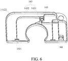
- FIG. 6 shows a schematic diagram of the bottom cover of the gas pathway 1412 of the gas generator 1 in one embodiment of the present invention.
- the bottom cover of the gas pathway 1412 comprises a pathway substrate 14122, wherein the pathway barrier sheet 1432 is configured on the pathway substrate 14122.
- the gas pathway 141 meanderingly distributed over the condensate filter device 14 is formed when the top cover of the gas pathway 1411 is combined with the bottom cover of the gas pathway 1412.
- the pathway substrate 14122 and the isolated component 143 are formed integrally by one process.
- the embodiment further comprises a humidification device 18 connected between the condensate filter device 14 and the atomizing device 16, wherein the humidification device 18 is used for further moisturizing and filtering the filtered gas with hydrogen received from the vent 145 and outputting the filtered gas with hydrogen to the atomizing device 16.
- the humidification device 18 comprises a water-adding hole 181, a condensed gas connected channel 182, a humidification tank 183, and a top cover of the humidification tank 184, wherein a humidification space is formed when the humidification tank 183 is combined with the top cover of the humidification tank 184.
- the condensed gas connected channel 182 is connected between the vent 145 of the condensate filter device 14 and the humidification space for inputting the filtered gas with hydrogen to the humidification space.
- the water-adding hole 181 is used for adding a humidification liquid into the humidification space.
- the outlet of the condensed gas connected channel can comprise a filter screen for further filtering and purifying the filtered gas with hydrogen.
- the atomizing device 16 comprises an atomization oscillator 161, an atomization chamber 162, a filtered gas connected channel 163, and a healthy gas outlet 164.
- the atomization chamber 162 is used for containing an atomizing solution.
- the atomization oscillator 161 is used for transferring the atomizing solution in the atomization chamber 162 to an atomizing gas.
- the atomization chamber 162 is used for mixing the atomizing gas with the filtered gas with hydrogen entering from the filtered gas connected channel 163 to generate a healthy gas.
- the healthy gas outlet 164 outputs the healthy gas for a user to use.
- the atomizing gas can be selected from a group comprising water vapor, an atomizing solution, a volatile essential oil, and any combination thereof.
- the atomizing device 16 can comprise a gas flow valve to adjust the amount of the outputted healthy gas so that the user can adjust the intake.
- the priority of the present invention is to provide a gas generator.
- a gas with hydrogen generated by an electrolytic cell is condensed and filtered out electrolytes by a condensate filter device, and then the gas with hydrogen is mixed with an atomizing gas generated by an atomizing device to generate a healthy gas for human to breathe suitably.
- the gas generator of the present invention comprises a humidification device connected between the condensate filter device and the atomizing device, wherein the humidification device is used for further filtering out impurities in the gas with hydrogen to provide a more suitable healthy gas for humans to breathe.
Landscapes
- Chemical & Material Sciences (AREA)
- Health & Medical Sciences (AREA)
- Engineering & Computer Science (AREA)
- Chemical Kinetics & Catalysis (AREA)
- Organic Chemistry (AREA)
- Electrochemistry (AREA)
- Materials Engineering (AREA)
- Metallurgy (AREA)
- Pulmonology (AREA)
- Life Sciences & Earth Sciences (AREA)
- Veterinary Medicine (AREA)
- Emergency Medicine (AREA)
- Public Health (AREA)
- Anesthesiology (AREA)
- Biomedical Technology (AREA)
- Heart & Thoracic Surgery (AREA)
- Hematology (AREA)
- General Health & Medical Sciences (AREA)
- Animal Behavior & Ethology (AREA)
- Inorganic Chemistry (AREA)
- Automation & Control Theory (AREA)
- Analytical Chemistry (AREA)
- Electrolytic Production Of Non-Metals, Compounds, Apparatuses Therefor (AREA)
- Feeding, Discharge, Calcimining, Fusing, And Gas-Generation Devices (AREA)
- Separation Using Semi-Permeable Membranes (AREA)
Claims (9)
- Gasgenerator (1), aufweisend eine elektrolytische Zelle (12), und wobei die elektrolytische Zelle (12) ein elektrolysiertes Wasser enthält, das einen Elektrolyten aufweist, wobei die elektrolytische Zelle (12) zum Elektrolysieren des elektrolysierten Wassers verwendet wird, um ein Gas mit Wasserstoff zu erzeugen, wobei der Gasgenerator (1) gekennzeichnet ist durch:eine Kondensatfiltervorrichtung (14), aufweisend einen Gasweg (141), einen Filter (142) und eine isolierte Komponente (143), wobei der Gasweg (141) zum Aufnehmen des Gases mit Wasserstoff verwendet wird und der Filter (142) im Gasweg (141) zum Filtern des Gases mit Wasserstoff konfiguriert ist, um ein gefiltertes Gas mit Wasserstoff zu erzeugen, und die isolierte Komponente (143) in der Kondensatfiltervorrichtung (14) konfiguriert ist, um die Bewegung des Filters (142) im Gasweg (141) zu beschränken, wobei die Kondensatfiltervorrichtung (14) einen Einlass (144) und eine Entlüftungsöffnung (145) aufweist, der Einlass konfiguriert ist, um das Gas mit Wasserstoff aufzunehmen, die Entlüftungsöffnung konfiguriert ist, um das gefilterte Gas mit Wasserstoff auszugeben, und die Kondensatfiltervorrichtung ferner eine untere Abdeckung des Gasweges (1412) aufweist, auf der die isolierte Komponente (143) positioniert ist, und der Filter (142) eine Mehrzahl von Filterfilmen aufweist, die durch die isolierte Komponente (143) getrennt und auf der gleichen Ebene der unteren Abdeckung des Gasweges (1412) verteilt sind; undeine Zerstäubungsvorrichtung (16) zum Aufnehmen des gefilterten Gases mit Wasserstoff, wobei die Zerstäubungsvorrichtung (16) ferner ein Zerstäubungsgas zum Mischen des gefilterten Gases mit Wasserstoff erzeugt, um ein gesundes Gas zu erzeugen.
- Gasgenerator gemäß Anspruch 1, wobei die isolierte Komponente (143) ferner einen isolierten Würfel (1431) oder eine Durchgangssperrfolie (1432) aufweist.
- Gasgenerator gemäß Anspruch 1, wobei die Kondensatfiltervorrichtung (14) eine obere Abdeckung des Gasweges (1411) aufweist, und die obere Abdeckung des Gasweges (1411) auf der unteren Abdeckung des Gasweges (1412) konfiguriert ist, und der Gasweg (141) zwischen der oberen Abdeckung des Gasweges (1411) und der unteren Abdeckung des Gasweges (1412) ausgebildet ist.
- Gasgenerator gemäß Anspruch 3, wobei die untere Abdeckung des Gasweges (1412) ein Wegsubstrat (14122) aufweist, und die isolierte Komponente (143) auf dem Wegsubstrat (14122) konfiguriert ist, und der Gasweg (141), der mäanderförmig über der Kondensatfiltervorrichtung (14) verteilt ist, zwischen der oberen Abdeckung des Gasweges (1411) und der unteren Abdeckung des Gasweges (1412) ausgebildet ist.
- Gasgenerator gemäß Anspruch 4, wobei das Wegsubstrat (14122) und die isolierte Komponente (143) integral durch einen Vorgang ausgebildet sind.
- Gasgenerator gemäß Anspruch 1, wobei der Einlass (144) und die Entlüftungsöffnung (145) jeweils mit dem Gasweg (141) verbunden sind und das Gas mit Wasserstoff durch den Einlass (144) hindurch in den Gasweg (141) eintritt.
- Gasgenerator gemäß Anspruch 6, wobei die isolierte Komponente (143) verwendet wird, um zu verhindern, dass der Filter (142) in den Einlass (144) oder die Entlüftungsöffnung (145) strömt, durch Beschränken der Bewegung des Filters (142) im Gasweg (141).
- Gasgenerator gemäß Anspruch 1, wobei der Filter (142) Asbest ist.
- Gasgenerator gemäß Anspruch 1, ferner aufweisend eine Befeuchtungsvorrichtung (18), die zwischen der Kondensatfiltervorrichtung (14) und der Zerstäubungsvorrichtung (16) angeschlossen ist, wobei die Befeuchtungsvorrichtung (18) zum weiteren Befeuchten und Filtern des gefilterten Gases mit Wasserstoff, das von der Entlüftungsöffnung (145) erhalten wird, und zum Ausgeben des gefilterten Gases mit Wasserstoff an die Zerstäubungsvorrichtung (16) verwendet wird.
Priority Applications (1)
| Application Number | Priority Date | Filing Date | Title |
|---|---|---|---|
| EP20209154.2A EP3808398B1 (de) | 2016-06-30 | 2017-06-30 | Gasgenerator |
Applications Claiming Priority (1)
| Application Number | Priority Date | Filing Date | Title |
|---|---|---|---|
| TW105120686A TWI629070B (zh) | 2016-06-30 | 2016-06-30 | 氣體產生器 |
Related Child Applications (1)
| Application Number | Title | Priority Date | Filing Date |
|---|---|---|---|
| EP20209154.2A Division EP3808398B1 (de) | 2016-06-30 | 2017-06-30 | Gasgenerator |
Publications (2)
| Publication Number | Publication Date |
|---|---|
| EP3263166A1 EP3263166A1 (de) | 2018-01-03 |
| EP3263166B1 true EP3263166B1 (de) | 2020-11-25 |
Family
ID=59383397
Family Applications (2)
| Application Number | Title | Priority Date | Filing Date |
|---|---|---|---|
| EP20209154.2A Active EP3808398B1 (de) | 2016-06-30 | 2017-06-30 | Gasgenerator |
| EP17178960.5A Active EP3263166B1 (de) | 2016-06-30 | 2017-06-30 | Gasgenerator |
Family Applications Before (1)
| Application Number | Title | Priority Date | Filing Date |
|---|---|---|---|
| EP20209154.2A Active EP3808398B1 (de) | 2016-06-30 | 2017-06-30 | Gasgenerator |
Country Status (5)
| Country | Link |
|---|---|
| US (2) | US10301726B2 (de) |
| EP (2) | EP3808398B1 (de) |
| JP (2) | JP6558600B2 (de) |
| CN (1) | CN107551374B (de) |
| TW (1) | TWI629070B (de) |
Families Citing this family (8)
| Publication number | Priority date | Publication date | Assignee | Title |
|---|---|---|---|---|
| CN110494055A (zh) * | 2017-04-12 | 2019-11-22 | 水银行股份有限公司 | 电解式气体吸引装置 |
| TWD195394S (zh) | 2018-08-17 | 2019-01-11 | 明光電機有限公司 | Part of a double-conducting special filter |
| TWI668332B (zh) * | 2018-12-04 | 2019-08-11 | 林信湧 | 堆疊式產氫裝置 |
| TWI715976B (zh) * | 2019-05-07 | 2021-01-11 | 大陸商上海潓美醫療科技有限公司 | 具有氫水杯之整合式氫氣產生器 |
| CN113621973B (zh) * | 2020-05-07 | 2024-08-09 | 上海潓美医疗科技有限公司 | 可选择性地调整气体流向的氢气产生器 |
| US20230347094A1 (en) * | 2020-07-23 | 2023-11-02 | Hsin-Yung Lin | Mixed gas generating system with oxygen generator or breathing tube |
| USD1026166S1 (en) * | 2021-06-03 | 2024-05-07 | Hsin-Yung Lin | Hydrogen generator |
| CN114110798B (zh) * | 2021-12-31 | 2025-06-03 | 上海中晨华瑞实业发展有限公司 | 一种多功能空气调节装置 |
Family Cites Families (15)
| Publication number | Priority date | Publication date | Assignee | Title |
|---|---|---|---|---|
| JPS50111776U (de) * | 1974-02-21 | 1975-09-11 | ||
| JPS60111776U (ja) | 1983-12-29 | 1985-07-29 | トヨタ自動車株式会社 | 自動車のラツゲ−ジドアインナ補強構造 |
| US5720789A (en) * | 1994-09-06 | 1998-02-24 | Lockheed Idaho Technologies Company | Method for contamination control and barrier apparatus with filter for containing waste materials that include dangerous particulate matter |
| JP3043306B2 (ja) * | 1997-12-25 | 2000-05-22 | スガ試験機株式会社 | 酸素・水素電解ガス発生装置 |
| JP4216892B1 (ja) | 2007-04-13 | 2009-01-28 | 優章 荒井 | 電解水の製造装置、電解水の製造方法および電解水 |
| JP2009072775A (ja) * | 2007-09-18 | 2009-04-09 | Samsung Electro-Mechanics Co Ltd | フィルタ、これを備えた水素発生器及び燃料電池発電システム |
| US20120211421A1 (en) * | 2010-05-14 | 2012-08-23 | Kyle Self | Systems and methods for processing co2 |
| US8337701B2 (en) * | 2011-03-14 | 2012-12-25 | Pall Corporation | Intravenous filter |
| TW201332656A (zh) | 2012-02-14 | 2013-08-16 | 友荃科技實業股份有限公司 | 保健氫氧氣供應設備 |
| DE202013012690U1 (de) * | 2012-07-26 | 2018-08-10 | Fritzmeier Umwelttechnik Gmbh & Co. Kg | Abgasfiltervorrichtung |
| CN203154454U (zh) * | 2013-02-11 | 2013-08-28 | 苏宝艳 | 输液过滤器 |
| CN109395224A (zh) | 2013-06-19 | 2019-03-01 | 上海潓美医疗科技有限公司 | 保健气体产生器 |
| CN108295352B (zh) * | 2014-01-07 | 2019-09-27 | 上海潓美医疗科技有限公司 | 保健气体产生系统 |
| US10465300B2 (en) * | 2014-10-16 | 2019-11-05 | Hsin-Yung Lin | Gas generator |
| TWI570275B (zh) * | 2014-10-16 | 2017-02-11 | 林信湧 | 氣體產生器 |
-
2016
- 2016-06-30 TW TW105120686A patent/TWI629070B/zh active
-
2017
- 2017-06-30 US US15/639,365 patent/US10301726B2/en active Active
- 2017-06-30 CN CN201710519343.2A patent/CN107551374B/zh active Active
- 2017-06-30 EP EP20209154.2A patent/EP3808398B1/de active Active
- 2017-06-30 JP JP2017128344A patent/JP6558600B2/ja active Active
- 2017-06-30 EP EP17178960.5A patent/EP3263166B1/de active Active
-
2019
- 2019-04-17 US US16/386,548 patent/US11214877B2/en active Active
- 2019-07-03 JP JP2019124241A patent/JP6976291B2/ja active Active
Non-Patent Citations (1)
| Title |
|---|
| None * |
Also Published As
| Publication number | Publication date |
|---|---|
| US10301726B2 (en) | 2019-05-28 |
| US20180002824A1 (en) | 2018-01-04 |
| US20190242020A1 (en) | 2019-08-08 |
| JP2019188207A (ja) | 2019-10-31 |
| TWI629070B (zh) | 2018-07-11 |
| EP3808398B1 (de) | 2024-02-28 |
| JP2018031070A (ja) | 2018-03-01 |
| JP6976291B2 (ja) | 2021-12-08 |
| US11214877B2 (en) | 2022-01-04 |
| EP3808398A1 (de) | 2021-04-21 |
| TW201801763A (zh) | 2018-01-16 |
| CN107551374A (zh) | 2018-01-09 |
| JP6558600B2 (ja) | 2019-08-14 |
| CN107551374B (zh) | 2020-05-08 |
| EP3263166A1 (de) | 2018-01-03 |
Similar Documents
| Publication | Publication Date | Title |
|---|---|---|
| EP3263166B1 (de) | Gasgenerator | |
| US11865265B2 (en) | Anti-explosion gas generator for health use | |
| EP3398641B1 (de) | Explosionsgeschützter gasgenerator zur gesundheitsverwendung | |
| US10010694B2 (en) | Gas generating system for health use | |
| US10190223B2 (en) | Gas generator | |
| US11286572B2 (en) | Gas generator | |
| US11918750B2 (en) | Healthy gas generating system | |
| EP4186550A1 (de) | System zur erzeugung von mischgas |
Legal Events
| Date | Code | Title | Description |
|---|---|---|---|
| PUAI | Public reference made under article 153(3) epc to a published international application that has entered the european phase |
Free format text: ORIGINAL CODE: 0009012 |
|
| STAA | Information on the status of an ep patent application or granted ep patent |
Free format text: STATUS: THE APPLICATION HAS BEEN PUBLISHED |
|
| AK | Designated contracting states |
Kind code of ref document: A1 Designated state(s): AL AT BE BG CH CY CZ DE DK EE ES FI FR GB GR HR HU IE IS IT LI LT LU LV MC MK MT NL NO PL PT RO RS SE SI SK SM TR |
|
| AX | Request for extension of the european patent |
Extension state: BA ME |
|
| STAA | Information on the status of an ep patent application or granted ep patent |
Free format text: STATUS: REQUEST FOR EXAMINATION WAS MADE |
|
| 17P | Request for examination filed |
Effective date: 20180627 |
|
| RBV | Designated contracting states (corrected) |
Designated state(s): AL AT BE BG CH CY CZ DE DK EE ES FI FR GB GR HR HU IE IS IT LI LT LU LV MC MK MT NL NO PL PT RO RS SE SI SK SM TR |
|
| STAA | Information on the status of an ep patent application or granted ep patent |
Free format text: STATUS: EXAMINATION IS IN PROGRESS |
|
| 17Q | First examination report despatched |
Effective date: 20191016 |
|
| GRAP | Despatch of communication of intention to grant a patent |
Free format text: ORIGINAL CODE: EPIDOSNIGR1 |
|
| STAA | Information on the status of an ep patent application or granted ep patent |
Free format text: STATUS: GRANT OF PATENT IS INTENDED |
|
| INTG | Intention to grant announced |
Effective date: 20200619 |
|
| GRAS | Grant fee paid |
Free format text: ORIGINAL CODE: EPIDOSNIGR3 |
|
| GRAA | (expected) grant |
Free format text: ORIGINAL CODE: 0009210 |
|
| STAA | Information on the status of an ep patent application or granted ep patent |
Free format text: STATUS: THE PATENT HAS BEEN GRANTED |
|
| AK | Designated contracting states |
Kind code of ref document: B1 Designated state(s): AL AT BE BG CH CY CZ DE DK EE ES FI FR GB GR HR HU IE IS IT LI LT LU LV MC MK MT NL NO PL PT RO RS SE SI SK SM TR |
|
| REG | Reference to a national code |
Ref country code: GB Ref legal event code: FG4D |
|
| REG | Reference to a national code |
Ref country code: CH Ref legal event code: EP |
|
| REG | Reference to a national code |
Ref country code: DE Ref legal event code: R096 Ref document number: 602017028106 Country of ref document: DE |
|
| REG | Reference to a national code |
Ref country code: AT Ref legal event code: REF Ref document number: 1337577 Country of ref document: AT Kind code of ref document: T Effective date: 20201215 |
|
| REG | Reference to a national code |
Ref country code: IE Ref legal event code: FG4D |
|
| REG | Reference to a national code |
Ref country code: NL Ref legal event code: FP |
|
| REG | Reference to a national code |
Ref country code: AT Ref legal event code: MK05 Ref document number: 1337577 Country of ref document: AT Kind code of ref document: T Effective date: 20201125 |
|
| PG25 | Lapsed in a contracting state [announced via postgrant information from national office to epo] |
Ref country code: NO Free format text: LAPSE BECAUSE OF FAILURE TO SUBMIT A TRANSLATION OF THE DESCRIPTION OR TO PAY THE FEE WITHIN THE PRESCRIBED TIME-LIMIT Effective date: 20210225 Ref country code: PT Free format text: LAPSE BECAUSE OF FAILURE TO SUBMIT A TRANSLATION OF THE DESCRIPTION OR TO PAY THE FEE WITHIN THE PRESCRIBED TIME-LIMIT Effective date: 20210325 Ref country code: RS Free format text: LAPSE BECAUSE OF FAILURE TO SUBMIT A TRANSLATION OF THE DESCRIPTION OR TO PAY THE FEE WITHIN THE PRESCRIBED TIME-LIMIT Effective date: 20201125 Ref country code: GR Free format text: LAPSE BECAUSE OF FAILURE TO SUBMIT A TRANSLATION OF THE DESCRIPTION OR TO PAY THE FEE WITHIN THE PRESCRIBED TIME-LIMIT Effective date: 20210226 Ref country code: FI Free format text: LAPSE BECAUSE OF FAILURE TO SUBMIT A TRANSLATION OF THE DESCRIPTION OR TO PAY THE FEE WITHIN THE PRESCRIBED TIME-LIMIT Effective date: 20201125 |
|
| PG25 | Lapsed in a contracting state [announced via postgrant information from national office to epo] |
Ref country code: AT Free format text: LAPSE BECAUSE OF FAILURE TO SUBMIT A TRANSLATION OF THE DESCRIPTION OR TO PAY THE FEE WITHIN THE PRESCRIBED TIME-LIMIT Effective date: 20201125 Ref country code: IS Free format text: LAPSE BECAUSE OF FAILURE TO SUBMIT A TRANSLATION OF THE DESCRIPTION OR TO PAY THE FEE WITHIN THE PRESCRIBED TIME-LIMIT Effective date: 20210325 Ref country code: LV Free format text: LAPSE BECAUSE OF FAILURE TO SUBMIT A TRANSLATION OF THE DESCRIPTION OR TO PAY THE FEE WITHIN THE PRESCRIBED TIME-LIMIT Effective date: 20201125 Ref country code: PL Free format text: LAPSE BECAUSE OF FAILURE TO SUBMIT A TRANSLATION OF THE DESCRIPTION OR TO PAY THE FEE WITHIN THE PRESCRIBED TIME-LIMIT Effective date: 20201125 Ref country code: BG Free format text: LAPSE BECAUSE OF FAILURE TO SUBMIT A TRANSLATION OF THE DESCRIPTION OR TO PAY THE FEE WITHIN THE PRESCRIBED TIME-LIMIT Effective date: 20210225 Ref country code: SE Free format text: LAPSE BECAUSE OF FAILURE TO SUBMIT A TRANSLATION OF THE DESCRIPTION OR TO PAY THE FEE WITHIN THE PRESCRIBED TIME-LIMIT Effective date: 20201125 |
|
| REG | Reference to a national code |
Ref country code: LT Ref legal event code: MG9D |
|
| PG25 | Lapsed in a contracting state [announced via postgrant information from national office to epo] |
Ref country code: HR Free format text: LAPSE BECAUSE OF FAILURE TO SUBMIT A TRANSLATION OF THE DESCRIPTION OR TO PAY THE FEE WITHIN THE PRESCRIBED TIME-LIMIT Effective date: 20201125 |
|
| PG25 | Lapsed in a contracting state [announced via postgrant information from national office to epo] |
Ref country code: RO Free format text: LAPSE BECAUSE OF FAILURE TO SUBMIT A TRANSLATION OF THE DESCRIPTION OR TO PAY THE FEE WITHIN THE PRESCRIBED TIME-LIMIT Effective date: 20201125 Ref country code: SK Free format text: LAPSE BECAUSE OF FAILURE TO SUBMIT A TRANSLATION OF THE DESCRIPTION OR TO PAY THE FEE WITHIN THE PRESCRIBED TIME-LIMIT Effective date: 20201125 Ref country code: CZ Free format text: LAPSE BECAUSE OF FAILURE TO SUBMIT A TRANSLATION OF THE DESCRIPTION OR TO PAY THE FEE WITHIN THE PRESCRIBED TIME-LIMIT Effective date: 20201125 Ref country code: EE Free format text: LAPSE BECAUSE OF FAILURE TO SUBMIT A TRANSLATION OF THE DESCRIPTION OR TO PAY THE FEE WITHIN THE PRESCRIBED TIME-LIMIT Effective date: 20201125 Ref country code: LT Free format text: LAPSE BECAUSE OF FAILURE TO SUBMIT A TRANSLATION OF THE DESCRIPTION OR TO PAY THE FEE WITHIN THE PRESCRIBED TIME-LIMIT Effective date: 20201125 Ref country code: SM Free format text: LAPSE BECAUSE OF FAILURE TO SUBMIT A TRANSLATION OF THE DESCRIPTION OR TO PAY THE FEE WITHIN THE PRESCRIBED TIME-LIMIT Effective date: 20201125 |
|
| REG | Reference to a national code |
Ref country code: DE Ref legal event code: R097 Ref document number: 602017028106 Country of ref document: DE |
|
| PG25 | Lapsed in a contracting state [announced via postgrant information from national office to epo] |
Ref country code: DK Free format text: LAPSE BECAUSE OF FAILURE TO SUBMIT A TRANSLATION OF THE DESCRIPTION OR TO PAY THE FEE WITHIN THE PRESCRIBED TIME-LIMIT Effective date: 20201125 |
|
| PLBE | No opposition filed within time limit |
Free format text: ORIGINAL CODE: 0009261 |
|
| STAA | Information on the status of an ep patent application or granted ep patent |
Free format text: STATUS: NO OPPOSITION FILED WITHIN TIME LIMIT |
|
| PG25 | Lapsed in a contracting state [announced via postgrant information from national office to epo] |
Ref country code: AL Free format text: LAPSE BECAUSE OF FAILURE TO SUBMIT A TRANSLATION OF THE DESCRIPTION OR TO PAY THE FEE WITHIN THE PRESCRIBED TIME-LIMIT Effective date: 20201125 |
|
| 26N | No opposition filed |
Effective date: 20210826 |
|
| PG25 | Lapsed in a contracting state [announced via postgrant information from national office to epo] |
Ref country code: SI Free format text: LAPSE BECAUSE OF FAILURE TO SUBMIT A TRANSLATION OF THE DESCRIPTION OR TO PAY THE FEE WITHIN THE PRESCRIBED TIME-LIMIT Effective date: 20201125 |
|
| PG25 | Lapsed in a contracting state [announced via postgrant information from national office to epo] |
Ref country code: ES Free format text: LAPSE BECAUSE OF FAILURE TO SUBMIT A TRANSLATION OF THE DESCRIPTION OR TO PAY THE FEE WITHIN THE PRESCRIBED TIME-LIMIT Effective date: 20201125 Ref country code: MC Free format text: LAPSE BECAUSE OF FAILURE TO SUBMIT A TRANSLATION OF THE DESCRIPTION OR TO PAY THE FEE WITHIN THE PRESCRIBED TIME-LIMIT Effective date: 20201125 |
|
| REG | Reference to a national code |
Ref country code: CH Ref legal event code: PL |
|
| REG | Reference to a national code |
Ref country code: BE Ref legal event code: MM Effective date: 20210630 |
|
| PG25 | Lapsed in a contracting state [announced via postgrant information from national office to epo] |
Ref country code: LU Free format text: LAPSE BECAUSE OF NON-PAYMENT OF DUE FEES Effective date: 20210630 |
|
| PG25 | Lapsed in a contracting state [announced via postgrant information from national office to epo] |
Ref country code: LI Free format text: LAPSE BECAUSE OF NON-PAYMENT OF DUE FEES Effective date: 20210630 Ref country code: IE Free format text: LAPSE BECAUSE OF NON-PAYMENT OF DUE FEES Effective date: 20210630 Ref country code: CH Free format text: LAPSE BECAUSE OF NON-PAYMENT OF DUE FEES Effective date: 20210630 |
|
| PG25 | Lapsed in a contracting state [announced via postgrant information from national office to epo] |
Ref country code: IS Free format text: LAPSE BECAUSE OF FAILURE TO SUBMIT A TRANSLATION OF THE DESCRIPTION OR TO PAY THE FEE WITHIN THE PRESCRIBED TIME-LIMIT Effective date: 20210325 |
|
| PG25 | Lapsed in a contracting state [announced via postgrant information from national office to epo] |
Ref country code: BE Free format text: LAPSE BECAUSE OF NON-PAYMENT OF DUE FEES Effective date: 20210630 |
|
| PG25 | Lapsed in a contracting state [announced via postgrant information from national office to epo] |
Ref country code: HU Free format text: LAPSE BECAUSE OF FAILURE TO SUBMIT A TRANSLATION OF THE DESCRIPTION OR TO PAY THE FEE WITHIN THE PRESCRIBED TIME-LIMIT; INVALID AB INITIO Effective date: 20170630 |
|
| PG25 | Lapsed in a contracting state [announced via postgrant information from national office to epo] |
Ref country code: CY Free format text: LAPSE BECAUSE OF FAILURE TO SUBMIT A TRANSLATION OF THE DESCRIPTION OR TO PAY THE FEE WITHIN THE PRESCRIBED TIME-LIMIT Effective date: 20201125 |
|
| PG25 | Lapsed in a contracting state [announced via postgrant information from national office to epo] |
Ref country code: MK Free format text: LAPSE BECAUSE OF FAILURE TO SUBMIT A TRANSLATION OF THE DESCRIPTION OR TO PAY THE FEE WITHIN THE PRESCRIBED TIME-LIMIT Effective date: 20201125 |
|
| PG25 | Lapsed in a contracting state [announced via postgrant information from national office to epo] |
Ref country code: MT Free format text: LAPSE BECAUSE OF FAILURE TO SUBMIT A TRANSLATION OF THE DESCRIPTION OR TO PAY THE FEE WITHIN THE PRESCRIBED TIME-LIMIT Effective date: 20201125 |
|
| PGFP | Annual fee paid to national office [announced via postgrant information from national office to epo] |
Ref country code: DE Payment date: 20250910 Year of fee payment: 9 |
|
| PG25 | Lapsed in a contracting state [announced via postgrant information from national office to epo] |
Ref country code: TR Free format text: LAPSE BECAUSE OF FAILURE TO SUBMIT A TRANSLATION OF THE DESCRIPTION OR TO PAY THE FEE WITHIN THE PRESCRIBED TIME-LIMIT Effective date: 20201125 |
|
| PGFP | Annual fee paid to national office [announced via postgrant information from national office to epo] |
Ref country code: NL Payment date: 20251112 Year of fee payment: 9 |
|
| PGFP | Annual fee paid to national office [announced via postgrant information from national office to epo] |
Ref country code: GB Payment date: 20251114 Year of fee payment: 9 |
|
| PGFP | Annual fee paid to national office [announced via postgrant information from national office to epo] |
Ref country code: IT Payment date: 20251121 Year of fee payment: 9 |
|
| PGFP | Annual fee paid to national office [announced via postgrant information from national office to epo] |
Ref country code: FR Payment date: 20251125 Year of fee payment: 9 |