EP3262913B1 - Épandeur agricole doté d'un centre de commande - Google Patents
Épandeur agricole doté d'un centre de commande Download PDFInfo
- Publication number
- EP3262913B1 EP3262913B1 EP17401067.8A EP17401067A EP3262913B1 EP 3262913 B1 EP3262913 B1 EP 3262913B1 EP 17401067 A EP17401067 A EP 17401067A EP 3262913 B1 EP3262913 B1 EP 3262913B1
- Authority
- EP
- European Patent Office
- Prior art keywords
- cover
- operating
- spreader machine
- supply container
- calibration
- Prior art date
- Legal status (The legal status is an assumption and is not a legal conclusion. Google has not performed a legal analysis and makes no representation as to the accuracy of the status listed.)
- Active
Links
Images

Classifications
-
- A—HUMAN NECESSITIES
- A01—AGRICULTURE; FORESTRY; ANIMAL HUSBANDRY; HUNTING; TRAPPING; FISHING
- A01C—PLANTING; SOWING; FERTILISING
- A01C7/00—Sowing
- A01C7/08—Broadcast seeders; Seeders depositing seeds in rows
- A01C7/12—Seeders with feeding wheels
- A01C7/123—Housings for feed rollers or wheels
-
- A—HUMAN NECESSITIES
- A01—AGRICULTURE; FORESTRY; ANIMAL HUSBANDRY; HUNTING; TRAPPING; FISHING
- A01C—PLANTING; SOWING; FERTILISING
- A01C7/00—Sowing
- A01C7/08—Broadcast seeders; Seeders depositing seeds in rows
- A01C7/10—Devices for adjusting the seed-box ; Regulation of machines for depositing quantities at intervals
- A01C7/107—Calibration of the seed rate
-
- A—HUMAN NECESSITIES
- A01—AGRICULTURE; FORESTRY; ANIMAL HUSBANDRY; HUNTING; TRAPPING; FISHING
- A01C—PLANTING; SOWING; FERTILISING
- A01C15/00—Fertiliser distributors
- A01C15/005—Undercarriages, tanks, hoppers, stirrers specially adapted for seeders or fertiliser distributors
- A01C15/006—Hoppers
Definitions
- the invention relates to an agricultural distribution machine according to the preamble of claim 1.
- Such a distributor is in the DE 10 2006 011 197 A1 described.
- the distributor described has a reservoir, which is supported on a frame.
- the frame in turn is supported by ground wheels or by means of a roller unit on the ground.
- the reservoir is associated with at least one metering.
- Below the metering a bottom flap is arranged, the setting is done by means of a Bodenklappeneinstellü.
- Below the dosing can be arranged to carry out a calibration Abwind anyer.
- a calibration flap is moved from a working position into a calibration and / or maintenance position by means of a calibration flap setting unit.
- the setting units of the distributor are combined in an operating center.
- the operating center is arranged on the left in the direction of the distribution machine.
- the invention is therefore based on the object to provide an arrangement which is suitable to ensure the coverage of the setting units and at the same time for the distribution process suitable settings of the setting units.
- the operating center can be covered by means of a cover and the cover can be moved to a calibration and / or maintenance position and a working position, the inner contour of the cover being shaped such that the cover is in its working position can be brought if all adjustment units combined in the operating center are in a suitable working position.
- the control center can not be covered with the cover when the bottom flaps are in the emptying position.
- the calibration is not in its working position, but in his necessary for the calibration calibration and / or maintenance position. In both exemplary cases, the movement of the cover into its working position is blocked by the inner contour of the cover colliding with the adjustment units or with the calibration container.
- the inner contour of the cover is designed to be variable so that the cover can be brought into its working position only when all the adjustment units combined in the operating center are in a specially set working position.
- the operator adjusts the distribution machine by means of the setting units of the operating center according to the impending distribution process.
- the adjustment units are in a specific work position for the upcoming distribution process.
- By adapting the inner contour of the cover to this special working position of the adjustment units of the operating center it is possible to move the cover into its position Working position only take place when the settings of the adjustment units and the inner contour of the cover match each other. It is therefore necessary to deliberately coordinate the positions of the adjustment units and the inner contour of the cover. As a result, additional safety is achieved for the operator and the risk of incorrect operation, for example due to carelessness or distraction, is further reduced.
- the cover of the control center is designed as a cover flap and is pivotable about a pivot axis pivoted on the reservoir.
- the operator can easily open and close the cover.
- the cover does not have to be laboriously completely attached or removed.
- a cover flap corresponds to the working position of the closed cover, the calibration and / or maintenance position of the open cover.
- the pivot axis extends in at least approximately vertical or at least approximately horizontal direction.
- a horizontal pivot axis an articulation of the cover in the upper region of the reservoir is conceivable.
- a tilted in calibration and / or maintenance position cover the operator during the calibration and / or maintenance process as a shelter against sunlight or rainfall serve.
- the cover can be moved door-like. This has the advantage that no complex kinematics is needed to swing the cover up and keep it safely in the high calibration and / or maintenance position.
- the cover pivotably hinged to the reservoir can be fixed in its calibration and / or maintenance position and / or in its working position.
- the fixation in the working position ensures that the adjustment units of the operating center are not exposed during a distribution process and are adjusted undesirably. Due to the fixation in the calibration and / or maintenance position is achieved that the cover does not fall during the execution of the calibration process by the operator, for example by a gust of wind and thus disturbs or endangers the operator while performing his duties.
- the control center has storage space for storing tools.
- the tools stored in the control center are protected against contamination and / or weathering.
- the risk of loss due to storage in a largely closed storage space is significantly reduced.
- the essential advantage of this embodiment is the accessibility of the tools. When stored at the location of the calibration and / or maintenance operation, the tools required by the operator performing the calibration and / or maintenance operation are easily accessible at any time during the calibration and / or maintenance process.
- the essential tools required for a calibration and / or maintenance operation are the calibration container or a weighing device provided for weighing the calibration container. It is therefore advantageous that at least the calibration container and a weighing device are mounted in the storage space of the operator control center.
- Typical distribution machines have a loading web above the dispensing elements. This is used to load the reservoir and / or a control of the load and / or the level of the reservoir. So that an operator has the shortest paths possible, the loading web usually comprises an ascent on the left side of the storage container in the working direction.
- the rise has a working position and a calibration and / or maintenance position and can be moved between the two positions.
- the rise in its calibration and / or maintenance position has a fastening element to which a weighing device for the calibration container can be fastened.
- a fastening element to which a weighing device for the calibration container can be fastened.
- All for the Calibration and / or maintenance process necessary device s are arranged in the area and / or in the vicinity of the control center.
- a good comparability of the weighing results is given.
- An agricultural distributor 1 which in the example chosen the Fig. 1 to 8 is designed as a seeder, has a reservoir 2 for storing material to be distributed.
- the storage container 2 is supported by means of supporting elements 3 on the frame 4 of a roller unit 5 assigned to the distributor 1, as in FIG Fig. 1 and 2 shown.
- the lower region of the storage container 2 is designed as a discharge region, in which not shown Outlet openings are arranged.
- About the outlet openings the material to be distributed is delivered to Ausbringierin 6 leading lines 7.
- the Ausbringemia 6 are arranged in the working direction A behind the roller unit 5.
- a plurality of dosing 8 are arranged.
- the output to the lines 7 amount of material to be distributed is set.
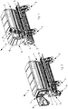
- Below the metering at least approximately cylindrically shaped Abwind anyer 9 are arranged, as in the Fig. 2 and 4 is shown.
- a loading web 10 is arranged. Via a rise 11, the loading web 10 is entered, for example, for loading the storage container 2 or for visual inspection of the container level by an operator.
- the rise 11 of the loading web 10 is in a working position 12, shown in FIG Fig. 1 and a calibration and / or maintenance position 13, shown in FIG Fig. 2 , can be moved.
- an operating center 14 On the left in the direction of A side of the reservoir 2, an operating center 14 is arranged. Under a cover 15 pivotable about an at least approximately vertical pivot axis, essential adjustment units 16 of the distributor 1 are combined in the control center 14.
- the cover 15 has a working position 17, shown in FIG Fig. 3 , and a calibration and / or maintenance position 18, shown in FIG Fig. 4 , on.
- the adjustment units 16 combined in the control center 14 include, for example, the adjustment unit of the metering device 8, the bottom flap adjustment unit and / or the calibration flap adjustment unit.
- the adjustment units typically have a plurality of possible working positions and one calibration and / or maintenance position each.
- the operating center 14 comprises a storage space 19 in which tools required for the calibration and / or maintenance process are stored.
- tools are at least a bucket and a weighing device.
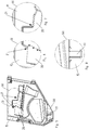
- the inner contour of the pivotally hinged cover 15 is in Fig. 5 shown.
- the inner contour is designed such that it interacts with the adjusting units 16. Is provided by the operator to spend the cover 15 in its working position 17, this is possible only if none of the summarized in the control center 14 adjusting units 16 are in their respective calibration and / or maintenance position.
- Fig. 6 and Fig. 7 the specially shaped areas (i) and (ii) of the inner contour of the cover 15 are shown. They interact with the adjustment units 16 such that the movement of the cover 15 to its working position is blocked when the adjustment units 16 are in their respective calibration and / or maintenance positions.
- the adjusting units 16 abut against the mold parts 20 of the inner contour of the cover 15. Only when the setting units 16 are in a suitable working position for the distribution process, the adjusting units 16 engage in the recesses 21 of the inner contour of the cover 15. The cover 15 can then in spend their job 17.
- Fig. 8 shows the specially shaped area (iii) of the inner contour of the cover 15.
- This area has a recess 22.
- the recess 22 is provided analogously to the manner described for interaction with the suitably shaped calibration box 9.
- the calibration 9 has a calibration and / or maintenance position 23, the Fig. 4 and a working position rotated by 180 ° about a horizontal axis to the calibration and / or maintenance position 23.
- a suitable shaping of the calibration 9 is suitable for engagement in the recess 22.
- a positive connection is only achieved when the calibration 9 is in its working position.
- the cover 15 can be spent only in positive engagement with the calibration box 9 in its working position 17, otherwise the movement of the cover 15 is blocked in its working position 17 by a collision of the inner contour of the cover 15 and the calibration box 9.
Landscapes
- Life Sciences & Earth Sciences (AREA)
- Soil Sciences (AREA)
- Environmental Sciences (AREA)
- Catching Or Destruction (AREA)
Claims (8)
- Epandeur agricole (1) doté d'un réservoir de stockage (2) supporté sur un châssis (4), avec au moins un organe de dosage (8) entraîné en rotation associé au réservoir de stockage (2) et qui introduit la matière se trouvant dans le réservoir de stockage (2) en quantités réglables dans des conduits (7) menant à des éléments de dépôt (6), dans lequel ledit au moins un organe de dosage (8) peut être réglé au moyen d'une unité de réglage, avec au moins un clapet de fond associé au dispositif de dosage (8), dont la distance audit au moins un organe de dosage (8) peut être réglée au moyen d'une unité de réglage du clapet de fond, avec au moins un récipient rotatif (9), qui est disposé en dessous dudit au moins un organe de dosage (8) et qui peut être amené dans une position de travail et dans une position de calibrage et/ou d'attente (23), et/ou avec un clapet rotatif associé audit au moins un organe de dosage (8), qui peut être amené dans une position de travail et dans une position de calibrage et/ou d'attente au moyen d'une unité de réglage du clapet rotatif, dans lequel au moins une unité de réglage de transmission, l'unité de réglage du clapet de fond et/ou l'unité de réglage du clapet rotatif sont rassemblées dans un centre de commande (14) et le centre de commande (14) est disposé sur un côté de l'épandeur (1), de préférence sur le côté gauche du réservoir de stockage (2) dans la direction de travail (A), caractérisé en ce que le centre de commande (14) peut être recouvert par un couvercle (15) et le couvercle (15) peut être amené dans une position de calibrage et/ou d'attente (18) et dans une position de travail (17), dans lequel le contour intérieur du couvercle (15) est formé de telle manière que le couvercle (15) ne puisse être amené dans sa position de travail (17), que lorsque toutes les unités de réglage (16) rassemblées dans le centre de commande (14) se trouvent dans une position de travail appropriée.
- Epandeur (1) selon la revendication 1, caractérisé en ce que le contour intérieur du couvercle (15) est réalisé sous forme variable, de telle manière que le couvercle (15) ne puisse être amené dans sa position de travail (17) que lorsque toutes les unités de réglage (16) rassemblées dans le centre de commande (14) se trouvent dans une position de travail spécialement réglée.
- Epandeur (1) selon au moins une des revendications précédentes, caractérisé en ce que le couvercle (15) du centre de commande (14) est formé par un couvercle à rabattre et est articulé sur le réservoir de stockage (2) de façon pivotante autour d'un axe de pivotement.
- Epandeur (1) selon la revendication 3, caractérisé en ce que l'axe de pivotement s'étend dans une direction au moins approximativement verticale ou au moins approximativement horizontale.
- Epandeur (1) selon la revendication 3 ou la revendication 4, caractérisé en ce que le couvercle (15) articulé de façon pivotante sur le réservoir de stockage (2) peut être fixé dans sa position de calibrage et/ou d'attente (18) et/ou dans sa position de travail (17).
- Epandeur (1) selon au moins une des revendications précédentes, caractérisé en ce que le centre de commande (14) présente un espace de rangement (19) pour la conservation d'outils.
- Epandeur (1) selon la revendication 6, caractérisé en ce qu'au moins le récipient rotatif (9) et un dispositif de pesage sont supportés dans l'espace de rangement (19) du centre de commande (14).
- Epandeur (1) selon au moins une des revendications précédentes, dans lequel l'épandeur (1) présente au-dessus des éléments de dépôt (6) une passerelle de chargement (10), qui comprend un escalier d'accès (11) sur le côté gauche du réservoir de stockage (2) dans la direction de travail (A) et l'escalier d'accès (11) présente une position de travail (12) et une position de calibrage et/ou d'attente (13) et il peut être amené entre les deux positions, caractérisé en ce que l'escalier d'accès (11) dans sa position de calibrage et/ou d'attente (13) présente un élément de fixation, auquel un dispositif de pesage pour le récipient rotatif (9) peut être fixé.
Priority Applications (1)
| Application Number | Priority Date | Filing Date | Title |
|---|---|---|---|
| PL17401067T PL3262913T3 (pl) | 2016-07-01 | 2017-06-27 | Dystrybutor rolniczy z centrum sterowania |
Applications Claiming Priority (1)
| Application Number | Priority Date | Filing Date | Title |
|---|---|---|---|
| DE102016112059.6A DE102016112059A1 (de) | 2016-07-01 | 2016-07-01 | Landwirtschaftliche Verteilmaschine mit Bedienzentrum |
Publications (2)
| Publication Number | Publication Date |
|---|---|
| EP3262913A1 EP3262913A1 (fr) | 2018-01-03 |
| EP3262913B1 true EP3262913B1 (fr) | 2019-03-13 |
Family
ID=59363077
Family Applications (1)
| Application Number | Title | Priority Date | Filing Date |
|---|---|---|---|
| EP17401067.8A Active EP3262913B1 (fr) | 2016-07-01 | 2017-06-27 | Épandeur agricole doté d'un centre de commande |
Country Status (3)
| Country | Link |
|---|---|
| EP (1) | EP3262913B1 (fr) |
| DE (1) | DE102016112059A1 (fr) |
| PL (1) | PL3262913T3 (fr) |
Cited By (1)
| Publication number | Priority date | Publication date | Assignee | Title |
|---|---|---|---|---|
| US20220015282A1 (en) * | 2020-07-14 | 2022-01-20 | Greenvalley Equipment (2009) Inc. | Collection Device for Meter Calibration of Air Seeder Tanks |
Families Citing this family (1)
| Publication number | Priority date | Publication date | Assignee | Title |
|---|---|---|---|---|
| DE102019122915A1 (de) * | 2019-08-27 | 2021-03-04 | Horsch Maschinen Gmbh | Vorratsbehälter mit integrierter Beleuchtungseinrichtung und/oder integrierter Lade |
Family Cites Families (3)
| Publication number | Priority date | Publication date | Assignee | Title |
|---|---|---|---|---|
| DE29907696U1 (de) * | 1999-04-30 | 2000-09-07 | Amazonen Werke Dreyer H | Stufenloses Getriebe für insbesondere landwirtschaftliche Verteilmaschinen |
| DE102006011197A1 (de) | 2006-03-10 | 2007-09-13 | Rabe Agri Gmbh | Sämaschine |
| DE102013105447A1 (de) * | 2013-05-28 | 2014-12-18 | Amazonen-Werke H. Dreyer Gmbh & Co. Kg | Verteilmaschine |
-
2016
- 2016-07-01 DE DE102016112059.6A patent/DE102016112059A1/de not_active Withdrawn
-
2017
- 2017-06-27 EP EP17401067.8A patent/EP3262913B1/fr active Active
- 2017-06-27 PL PL17401067T patent/PL3262913T3/pl unknown
Non-Patent Citations (1)
| Title |
|---|
| None * |
Cited By (2)
| Publication number | Priority date | Publication date | Assignee | Title |
|---|---|---|---|---|
| US20220015282A1 (en) * | 2020-07-14 | 2022-01-20 | Greenvalley Equipment (2009) Inc. | Collection Device for Meter Calibration of Air Seeder Tanks |
| US11825764B2 (en) * | 2020-07-14 | 2023-11-28 | Greenvalley Equipment (2009) Inc. | Collection device for meter calibration of air seeder tanks |
Also Published As
| Publication number | Publication date |
|---|---|
| DE102016112059A1 (de) | 2018-01-04 |
| PL3262913T3 (pl) | 2019-09-30 |
| EP3262913A1 (fr) | 2018-01-03 |
Similar Documents
| Publication | Publication Date | Title |
|---|---|---|
| EP2057876B1 (fr) | Epandeur à double plaque | |
| EP3262913B1 (fr) | Épandeur agricole doté d'un centre de commande | |
| EP3165091B1 (fr) | Système de commande et de réglage d'une machine agricole | |
| DE202012007418U1 (de) | Zerkleinerungsvorrichtung | |
| DE2954406C2 (fr) | ||
| EP3262912B1 (fr) | Épandeur agricole doté de revêtement | |
| WO2013131640A2 (fr) | Procédé et dispositif de démontage et/ou de montage d'un extincteur dans un avion | |
| DE1782544B1 (de) | Kreiselzettwender | |
| DE2207484B2 (de) | Verfahren zur Steuerung der Mahlgutmenge in einer Mahlkammer eines Kugelmühlenrohres sowie Vorrichtung zur Durchführung dieses Verfahrens | |
| EP3300598A1 (fr) | Procédé et dispositif de pulvérisation permettant la distribution d'un fluide de pulvérisation sur une superficie agricole | |
| EP2364583B1 (fr) | Machine de répartition agricole | |
| DE2001715B2 (de) | Streugerät | |
| EP1164079B1 (fr) | Machine de remplissage avec silo rotatif | |
| EP3272215B1 (fr) | Pulvérisateur agricole | |
| EP3666406B1 (fr) | Lave-linge | |
| DE102012007855B4 (de) | Modulares System zur Manipulation vonWerkzeugen für mobile Arbeitsmaschinen | |
| DE102016014360A1 (de) | Fahrmischer | |
| EP2353358B1 (fr) | Dispositif agricole | |
| DE102017116453B3 (de) | Landwirtschaftliche Verteilmaschine | |
| DE202010017448U1 (de) | Kreissäge | |
| DE19652373C1 (de) | Flüssigkeitsverteiler, insbesondere Flüssigmistverteiler | |
| DE3931574A1 (de) | Gestell fuer bildschirmgeraete | |
| DE4419436C1 (de) | Selbstfahrender Mähdrescher mit Schrägfördererkanal | |
| DE4335255C2 (de) | Vorrichtung zum Handhaben von insbesondere pharmazeutischen Schüttgütern | |
| DE1483136C3 (de) | Vorrichtung zum Beschicken eines unterhalb eines Trichters befindlichen Förderers einer Maschine zum Sintern, Agglomerieren und/oder Rösten von Schüttgut |
Legal Events
| Date | Code | Title | Description |
|---|---|---|---|
| PUAI | Public reference made under article 153(3) epc to a published international application that has entered the european phase |
Free format text: ORIGINAL CODE: 0009012 |
|
| STAA | Information on the status of an ep patent application or granted ep patent |
Free format text: STATUS: THE APPLICATION HAS BEEN PUBLISHED |
|
| AK | Designated contracting states |
Kind code of ref document: A1 Designated state(s): AL AT BE BG CH CY CZ DE DK EE ES FI FR GB GR HR HU IE IS IT LI LT LU LV MC MK MT NL NO PL PT RO RS SE SI SK SM TR |
|
| AX | Request for extension of the european patent |
Extension state: BA ME |
|
| STAA | Information on the status of an ep patent application or granted ep patent |
Free format text: STATUS: REQUEST FOR EXAMINATION WAS MADE |
|
| 17P | Request for examination filed |
Effective date: 20180525 |
|
| RBV | Designated contracting states (corrected) |
Designated state(s): AL AT BE BG CH CY CZ DE DK EE ES FI FR GB GR HR HU IE IS IT LI LT LU LV MC MK MT NL NO PL PT RO RS SE SI SK SM TR |
|
| GRAP | Despatch of communication of intention to grant a patent |
Free format text: ORIGINAL CODE: EPIDOSNIGR1 |
|
| STAA | Information on the status of an ep patent application or granted ep patent |
Free format text: STATUS: GRANT OF PATENT IS INTENDED |
|
| INTG | Intention to grant announced |
Effective date: 20181005 |
|
| GRAS | Grant fee paid |
Free format text: ORIGINAL CODE: EPIDOSNIGR3 |
|
| GRAA | (expected) grant |
Free format text: ORIGINAL CODE: 0009210 |
|
| STAA | Information on the status of an ep patent application or granted ep patent |
Free format text: STATUS: THE PATENT HAS BEEN GRANTED |
|
| AK | Designated contracting states |
Kind code of ref document: B1 Designated state(s): AL AT BE BG CH CY CZ DE DK EE ES FI FR GB GR HR HU IE IS IT LI LT LU LV MC MK MT NL NO PL PT RO RS SE SI SK SM TR |
|
| REG | Reference to a national code |
Ref country code: GB Ref legal event code: FG4D Free format text: NOT ENGLISH |
|
| REG | Reference to a national code |
Ref country code: CH Ref legal event code: EP Ref country code: AT Ref legal event code: REF Ref document number: 1106408 Country of ref document: AT Kind code of ref document: T Effective date: 20190315 |
|
| REG | Reference to a national code |
Ref country code: IE Ref legal event code: FG4D Free format text: LANGUAGE OF EP DOCUMENT: GERMAN |
|
| REG | Reference to a national code |
Ref country code: DE Ref legal event code: R096 Ref document number: 502017000925 Country of ref document: DE |
|
| REG | Reference to a national code |
Ref country code: SE Ref legal event code: TRGR |
|
| REG | Reference to a national code |
Ref country code: NL Ref legal event code: MP Effective date: 20190313 |
|
| REG | Reference to a national code |
Ref country code: LT Ref legal event code: MG4D |
|
| PG25 | Lapsed in a contracting state [announced via postgrant information from national office to epo] |
Ref country code: LT Free format text: LAPSE BECAUSE OF FAILURE TO SUBMIT A TRANSLATION OF THE DESCRIPTION OR TO PAY THE FEE WITHIN THE PRESCRIBED TIME-LIMIT Effective date: 20190313 Ref country code: FI Free format text: LAPSE BECAUSE OF FAILURE TO SUBMIT A TRANSLATION OF THE DESCRIPTION OR TO PAY THE FEE WITHIN THE PRESCRIBED TIME-LIMIT Effective date: 20190313 Ref country code: NO Free format text: LAPSE BECAUSE OF FAILURE TO SUBMIT A TRANSLATION OF THE DESCRIPTION OR TO PAY THE FEE WITHIN THE PRESCRIBED TIME-LIMIT Effective date: 20190613 |
|
| PG25 | Lapsed in a contracting state [announced via postgrant information from national office to epo] |
Ref country code: RS Free format text: LAPSE BECAUSE OF FAILURE TO SUBMIT A TRANSLATION OF THE DESCRIPTION OR TO PAY THE FEE WITHIN THE PRESCRIBED TIME-LIMIT Effective date: 20190313 Ref country code: GR Free format text: LAPSE BECAUSE OF FAILURE TO SUBMIT A TRANSLATION OF THE DESCRIPTION OR TO PAY THE FEE WITHIN THE PRESCRIBED TIME-LIMIT Effective date: 20190614 Ref country code: BG Free format text: LAPSE BECAUSE OF FAILURE TO SUBMIT A TRANSLATION OF THE DESCRIPTION OR TO PAY THE FEE WITHIN THE PRESCRIBED TIME-LIMIT Effective date: 20190613 Ref country code: LV Free format text: LAPSE BECAUSE OF FAILURE TO SUBMIT A TRANSLATION OF THE DESCRIPTION OR TO PAY THE FEE WITHIN THE PRESCRIBED TIME-LIMIT Effective date: 20190313 Ref country code: NL Free format text: LAPSE BECAUSE OF FAILURE TO SUBMIT A TRANSLATION OF THE DESCRIPTION OR TO PAY THE FEE WITHIN THE PRESCRIBED TIME-LIMIT Effective date: 20190313 Ref country code: HR Free format text: LAPSE BECAUSE OF FAILURE TO SUBMIT A TRANSLATION OF THE DESCRIPTION OR TO PAY THE FEE WITHIN THE PRESCRIBED TIME-LIMIT Effective date: 20190313 |
|
| PG25 | Lapsed in a contracting state [announced via postgrant information from national office to epo] |
Ref country code: RO Free format text: LAPSE BECAUSE OF FAILURE TO SUBMIT A TRANSLATION OF THE DESCRIPTION OR TO PAY THE FEE WITHIN THE PRESCRIBED TIME-LIMIT Effective date: 20190313 Ref country code: CZ Free format text: LAPSE BECAUSE OF FAILURE TO SUBMIT A TRANSLATION OF THE DESCRIPTION OR TO PAY THE FEE WITHIN THE PRESCRIBED TIME-LIMIT Effective date: 20190313 Ref country code: ES Free format text: LAPSE BECAUSE OF FAILURE TO SUBMIT A TRANSLATION OF THE DESCRIPTION OR TO PAY THE FEE WITHIN THE PRESCRIBED TIME-LIMIT Effective date: 20190313 Ref country code: EE Free format text: LAPSE BECAUSE OF FAILURE TO SUBMIT A TRANSLATION OF THE DESCRIPTION OR TO PAY THE FEE WITHIN THE PRESCRIBED TIME-LIMIT Effective date: 20190313 Ref country code: SK Free format text: LAPSE BECAUSE OF FAILURE TO SUBMIT A TRANSLATION OF THE DESCRIPTION OR TO PAY THE FEE WITHIN THE PRESCRIBED TIME-LIMIT Effective date: 20190313 Ref country code: PT Free format text: LAPSE BECAUSE OF FAILURE TO SUBMIT A TRANSLATION OF THE DESCRIPTION OR TO PAY THE FEE WITHIN THE PRESCRIBED TIME-LIMIT Effective date: 20190713 Ref country code: AL Free format text: LAPSE BECAUSE OF FAILURE TO SUBMIT A TRANSLATION OF THE DESCRIPTION OR TO PAY THE FEE WITHIN THE PRESCRIBED TIME-LIMIT Effective date: 20190313 |
|
| PG25 | Lapsed in a contracting state [announced via postgrant information from national office to epo] |
Ref country code: SM Free format text: LAPSE BECAUSE OF FAILURE TO SUBMIT A TRANSLATION OF THE DESCRIPTION OR TO PAY THE FEE WITHIN THE PRESCRIBED TIME-LIMIT Effective date: 20190313 |
|
| REG | Reference to a national code |
Ref country code: DE Ref legal event code: R097 Ref document number: 502017000925 Country of ref document: DE |
|
| PG25 | Lapsed in a contracting state [announced via postgrant information from national office to epo] |
Ref country code: IS Free format text: LAPSE BECAUSE OF FAILURE TO SUBMIT A TRANSLATION OF THE DESCRIPTION OR TO PAY THE FEE WITHIN THE PRESCRIBED TIME-LIMIT Effective date: 20190713 |
|
| PLBE | No opposition filed within time limit |
Free format text: ORIGINAL CODE: 0009261 |
|
| STAA | Information on the status of an ep patent application or granted ep patent |
Free format text: STATUS: NO OPPOSITION FILED WITHIN TIME LIMIT |
|
| PG25 | Lapsed in a contracting state [announced via postgrant information from national office to epo] |
Ref country code: MC Free format text: LAPSE BECAUSE OF FAILURE TO SUBMIT A TRANSLATION OF THE DESCRIPTION OR TO PAY THE FEE WITHIN THE PRESCRIBED TIME-LIMIT Effective date: 20190313 Ref country code: DK Free format text: LAPSE BECAUSE OF FAILURE TO SUBMIT A TRANSLATION OF THE DESCRIPTION OR TO PAY THE FEE WITHIN THE PRESCRIBED TIME-LIMIT Effective date: 20190313 |
|
| 26N | No opposition filed |
Effective date: 20191216 |
|
| PG25 | Lapsed in a contracting state [announced via postgrant information from national office to epo] |
Ref country code: SI Free format text: LAPSE BECAUSE OF FAILURE TO SUBMIT A TRANSLATION OF THE DESCRIPTION OR TO PAY THE FEE WITHIN THE PRESCRIBED TIME-LIMIT Effective date: 20190313 |
|
| REG | Reference to a national code |
Ref country code: BE Ref legal event code: MM Effective date: 20190630 |
|
| PG25 | Lapsed in a contracting state [announced via postgrant information from national office to epo] |
Ref country code: TR Free format text: LAPSE BECAUSE OF FAILURE TO SUBMIT A TRANSLATION OF THE DESCRIPTION OR TO PAY THE FEE WITHIN THE PRESCRIBED TIME-LIMIT Effective date: 20190313 |
|
| PG25 | Lapsed in a contracting state [announced via postgrant information from national office to epo] |
Ref country code: IE Free format text: LAPSE BECAUSE OF NON-PAYMENT OF DUE FEES Effective date: 20190627 |
|
| PG25 | Lapsed in a contracting state [announced via postgrant information from national office to epo] |
Ref country code: BE Free format text: LAPSE BECAUSE OF NON-PAYMENT OF DUE FEES Effective date: 20190630 Ref country code: LU Free format text: LAPSE BECAUSE OF NON-PAYMENT OF DUE FEES Effective date: 20190627 |
|
| REG | Reference to a national code |
Ref country code: CH Ref legal event code: PL |
|
| PG25 | Lapsed in a contracting state [announced via postgrant information from national office to epo] |
Ref country code: CH Free format text: LAPSE BECAUSE OF NON-PAYMENT OF DUE FEES Effective date: 20200630 Ref country code: LI Free format text: LAPSE BECAUSE OF NON-PAYMENT OF DUE FEES Effective date: 20200630 |
|
| REG | Reference to a national code |
Ref country code: DE Ref legal event code: R081 Ref document number: 502017000925 Country of ref document: DE Owner name: AMAZONEN-WERKE H. DREYER SE & CO. KG, DE Free format text: FORMER OWNER: AMAZONEN-WERKE H. DREYER GMBH & CO. KG, 49205 HASBERGEN, DE |
|
| PG25 | Lapsed in a contracting state [announced via postgrant information from national office to epo] |
Ref country code: CY Free format text: LAPSE BECAUSE OF FAILURE TO SUBMIT A TRANSLATION OF THE DESCRIPTION OR TO PAY THE FEE WITHIN THE PRESCRIBED TIME-LIMIT Effective date: 20190313 |
|
| PG25 | Lapsed in a contracting state [announced via postgrant information from national office to epo] |
Ref country code: MT Free format text: LAPSE BECAUSE OF FAILURE TO SUBMIT A TRANSLATION OF THE DESCRIPTION OR TO PAY THE FEE WITHIN THE PRESCRIBED TIME-LIMIT Effective date: 20190313 Ref country code: HU Free format text: LAPSE BECAUSE OF FAILURE TO SUBMIT A TRANSLATION OF THE DESCRIPTION OR TO PAY THE FEE WITHIN THE PRESCRIBED TIME-LIMIT; INVALID AB INITIO Effective date: 20170627 |
|
| GBPC | Gb: european patent ceased through non-payment of renewal fee |
Effective date: 20210627 |
|
| PG25 | Lapsed in a contracting state [announced via postgrant information from national office to epo] |
Ref country code: GB Free format text: LAPSE BECAUSE OF NON-PAYMENT OF DUE FEES Effective date: 20210627 |
|
| PG25 | Lapsed in a contracting state [announced via postgrant information from national office to epo] |
Ref country code: MK Free format text: LAPSE BECAUSE OF FAILURE TO SUBMIT A TRANSLATION OF THE DESCRIPTION OR TO PAY THE FEE WITHIN THE PRESCRIBED TIME-LIMIT Effective date: 20190313 |
|
| PGFP | Annual fee paid to national office [announced via postgrant information from national office to epo] |
Ref country code: SE Payment date: 20230314 Year of fee payment: 7 |
|
| P01 | Opt-out of the competence of the unified patent court (upc) registered |
Effective date: 20230523 |
|
| PGFP | Annual fee paid to national office [announced via postgrant information from national office to epo] |
Ref country code: IT Payment date: 20230510 Year of fee payment: 7 Ref country code: FR Payment date: 20230510 Year of fee payment: 7 Ref country code: DE Payment date: 20230502 Year of fee payment: 7 |
|
| PGFP | Annual fee paid to national office [announced via postgrant information from national office to epo] |
Ref country code: PL Payment date: 20230417 Year of fee payment: 7 Ref country code: AT Payment date: 20230525 Year of fee payment: 7 |